JP2006512500A - Joint installation support device - Google Patents
Joint installation support device Download PDFInfo
- Publication number
- JP2006512500A JP2006512500A JP2004565009A JP2004565009A JP2006512500A JP 2006512500 A JP2006512500 A JP 2006512500A JP 2004565009 A JP2004565009 A JP 2004565009A JP 2004565009 A JP2004565009 A JP 2004565009A JP 2006512500 A JP2006512500 A JP 2006512500A
- Authority
- JP
- Japan
- Prior art keywords
- fabric
- edge
- attachment
- connection
- connection edge
- Prior art date
- Legal status (The legal status is an assumption and is not a legal conclusion. Google has not performed a legal analysis and makes no representation as to the accuracy of the status listed.)
- Pending
Links
Images


Classifications
-
- D—TEXTILES; PAPER
- D21—PAPER-MAKING; PRODUCTION OF CELLULOSE
- D21F—PAPER-MAKING MACHINES; METHODS OF PRODUCING PAPER THEREON
- D21F1/00—Wet end of machines for making continuous webs of paper
- D21F1/0027—Screen-cloths
- D21F1/0054—Seams thereof
-
- Y—GENERAL TAGGING OF NEW TECHNOLOGICAL DEVELOPMENTS; GENERAL TAGGING OF CROSS-SECTIONAL TECHNOLOGIES SPANNING OVER SEVERAL SECTIONS OF THE IPC; TECHNICAL SUBJECTS COVERED BY FORMER USPC CROSS-REFERENCE ART COLLECTIONS [XRACs] AND DIGESTS
- Y10—TECHNICAL SUBJECTS COVERED BY FORMER USPC
- Y10T—TECHNICAL SUBJECTS COVERED BY FORMER US CLASSIFICATION
- Y10T24/00—Buckles, buttons, clasps, etc.
- Y10T24/16—Belt fasteners
- Y10T24/1608—Hinged
-
- Y—GENERAL TAGGING OF NEW TECHNOLOGICAL DEVELOPMENTS; GENERAL TAGGING OF CROSS-SECTIONAL TECHNOLOGIES SPANNING OVER SEVERAL SECTIONS OF THE IPC; TECHNICAL SUBJECTS COVERED BY FORMER USPC CROSS-REFERENCE ART COLLECTIONS [XRACs] AND DIGESTS
- Y10—TECHNICAL SUBJECTS COVERED BY FORMER USPC
- Y10T—TECHNICAL SUBJECTS COVERED BY FORMER US CLASSIFICATION
- Y10T24/00—Buckles, buttons, clasps, etc.
- Y10T24/16—Belt fasteners
- Y10T24/1696—Hook and loop type fastener and zipper belt end connection
Landscapes
- Paper (AREA)
- Treatment Of Fiber Materials (AREA)
- Prostheses (AREA)
- Soil Working Implements (AREA)
- Sewing Machines And Sewing (AREA)
Abstract
Description
本発明は、抄紙技術に関する。より詳しくは、本発明は、抄紙機上で継ぎ合わせをする抄紙機の織物の両端を一緒に引っ張って一列に並べる継目取付支援装置に関する。 The present invention relates to a papermaking technique. More specifically, the present invention relates to a seam attachment support device that pulls together both ends of a fabric of a paper machine that is spliced together on a paper machine and arranges them in a line.
抄紙工程の中で、セルロース性繊維質巻取り紙は抄紙機の形成部において運動している形成織物の上に繊維質スラリー、即ちセルロース繊維の水分散液、を沈殿させることにより形成される。多量の水が形成織物の表面上に繊維質巻取り紙を残しながら、形成織物を通してスラリーから排出される。 During the paper making process, the cellulosic fibrous web is formed by precipitating a fibrous slurry, ie, an aqueous dispersion of cellulose fibers, on the forming fabric that is moving in the forming section of the paper machine. A large amount of water is drained from the slurry through the forming fabric, leaving a fibrous web on the surface of the forming fabric.
新しく形成されたセルロース性繊維質巻取り紙は、形成部から一連のプレスニップを含むプレス部に進む。セルロース性繊維質巻取り紙は、一つのプレス織物により、又は多くの場合二つのプレス織物の間に支持されてプレスニップを通過する。プレスニップでは、セルロース性繊維質巻取り紙は、そこから水を絞り出し、且つ紙シートの中にセルロース性繊維質巻取り紙を折込み巻取り紙にセルロース性繊維を互いに接着させる圧縮力を受ける。水は、プレス織物によって受容れられ、且つ理想的には、紙シートには戻らない。 The newly formed cellulosic fibrous web proceeds from the forming section to a pressing section that includes a series of press nips. The cellulosic fibrous web passes through the press nip, supported by a single press fabric, or often between two press fabrics. In the press nip, the cellulosic fibrous web is subjected to a compressive force that squeezes water therefrom and folds the cellulosic fibrous web into the paper sheet to adhere the cellulosic fibers to the web. Water is received by the press fabric and ideally does not return to the paper sheet.
紙シートは最後には蒸気により内部から加熱された少なくとも一連の回転可能な乾燥機ドラム又はシリンダーを含む乾燥機部に進む。新しく形成された紙シートはドラムの表面に対して紙シートを密着保持する乾燥機織物によりドラムの列の各々の周りを連続して蛇行する通路に案内される。加熱されたドラムは蒸発によって望ましいレベルにまで紙シートの含水量を減少させる。 The paper sheet finally proceeds to a dryer section containing at least a series of rotatable dryer drums or cylinders heated from the inside by steam. The newly formed paper sheet is guided into a continuous meandering path around each of the drum rows by a dryer fabric that holds the paper sheet tightly against the surface of the drum. The heated drum reduces the water content of the paper sheet to the desired level by evaporation.
形成、プレス及び乾燥機織物は、すべて抄紙機上でエンドレスループの形をとり且つコンベヤーと同様な機能をすることを認識すべきである。更に、製紙がかなりのスピードで進行する連続工程であることも認識されるべきである。換言すれば、繊維質スラリーが形成部で形成織物の上に連続的に沈殿させられる一方、新しく製造された紙シートはそれが乾燥機部から出た後ローラー上に連続的に巻き取られる。 It should be appreciated that the forming, pressing and dryer fabrics all take the form of endless loops on the paper machine and function in a similar manner to the conveyor. Furthermore, it should be recognized that papermaking is a continuous process that proceeds at considerable speed. In other words, the fibrous slurry is continuously precipitated on the forming fabric at the forming section, while the newly produced paper sheet is continuously wound on the rollers after it exits the dryer section.
織物は、多くの様々な形態をとる。例えば、それらはエンドレスに織られるか、或いは平織であって続いて継目を付けてエンドレスの形を与えられても良い。織られた織物は、代表的にはエンドレスループの形であるか、或いはその周りを縦に測定した特定の長さと、それを横切って横に測定した特定の幅とを有している形で継ぎ合わせ可能である。抄紙機の構成は、幅広く変化しているから、抄紙機織物の製造業者は彼らの顧客の抄紙機の特定の場所にぴったり合うことを要求される寸法で、織物及びその他の抄紙機織物を生産することが要求される。云うまでもなく、各織物は代表的には注文で作られねばならないから、この要求は製造工程を効率化することを困難にしている。 Textiles take many different forms. For example, they may be woven endlessly or plain woven and subsequently seamed to give an endless shape. Woven fabrics are typically in the form of endless loops or have a specific length measured longitudinally around them and a specific width measured transversely across them. Can be spliced. Because the configuration of the paper machine varies widely, manufacturers of paper machine fabrics produce fabrics and other paper machine fabrics at the dimensions required to fit exactly to their customers' specific machine locations. It is required to do. Needless to say, this requirement makes it difficult to streamline the manufacturing process because each fabric must typically be made to order.
最近の抄紙機の織物は、5〜33フィートの幅、40〜400フィートの長さ及び近似的に100〜3000ポンドの重量を有してもよい。これらの織物は磨り減って交換を必要とする。織物の交換は機械を停止し、磨り減った織物を取り除き、織物を据付のために組み立てて新しい織物を据え付けることを含む。多くの織物はエンドレスである一方、今日抄紙機のプレス部で使用されるこれらの内約半分は機械上で継ぎ合わせ可能(on−machine−seamable)である。一部の製紙工業工程ベルト(PIPB)は登録商標Transbeltとして知られるある種の移送ベルトのように、機械上の継目能力を持つべく目論まれている。織物の据付は織物の本体を機械の上に引っ張り上げてエンドレスベルトを形成するように織物の端部を連結することを含む。 Modern paper machine fabrics may have a width of 5 to 33 feet, a length of 40 to 400 feet, and a weight of approximately 100 to 3000 pounds. These fabrics wear out and require replacement. Changing the fabric includes shutting down the machine, removing the worn fabric, assembling the fabric for installation and installing a new fabric. While many fabrics are endless, about half of these used today in paper machine presses are on-machine-seamable on the machine. Some paper industry process belts (PIPB) are intended to have machine seam capability, such as a type of transfer belt known as the registered trademark Transbelt. Installation of the fabric involves joining the ends of the fabric so that the fabric body is pulled over the machine to form an endless belt.
要するに、どんな運用可能な織物の継目領域も負荷の下で作動させる必要があるし又製造される紙製品に継目領域による周期的なマークが付くことを予防するために、織物の残りの部分と同じ水や空気に対する透過率を持たねばならない。 In short, any operable fabric seam area must be operated under load and to prevent the paper product being manufactured from being periodically marked by the seam area, It must have the same water and air permeability.
これらの必要条件により表される相当の技術的障害にも拘わらず、これらが据付出来ることに関する比較上の容易さと安全性の故に、継ぎ合わせ可能な織物を開発することは強く望まれている。 Despite the considerable technical hurdles represented by these requirements, it is highly desirable to develop seams that can be seamed because of the relative ease and safety with which they can be installed.
継ぎ合わせを容易にするため、多くの最新の織物は、織物の両端の横の縁部に継ぎ合わせループを持つ。継ぎ合わせループそれ自身は織物の機械方向(MD)の糸により形成される。継目は、織物の両端を一緒に持ち寄ることにより、織物の両端で継ぎ合わせループを噛み合わせることにより、そして織物の両端を一緒に固定するよう噛み合わせた継ぎ合わせループにより規定された通路を通って、所謂ピン、又は軸棒を案内することにより形成される。 To facilitate seaming, many modern fabrics have seaming loops at the lateral edges at both ends of the fabric. The seaming loop itself is formed by the machine direction (MD) yarn of the fabric. The seam passes through a passage defined by bringing the ends of the fabric together, by engaging the seam loops at both ends of the fabric, and by the seam loops engaged to secure the ends of the fabric together. It is formed by guiding so-called pins or shaft bars.
代案として、単繊維継ぎ合わせ螺旋が抄紙機の織物の両端の各で継ぎ合わせループに取り付けられても良い。単繊維継ぎ合わせ螺旋は少なくとも一つの結合糸により継ぎ合わせループに結合される。織物の両端で螺旋のコイルはそこで通常螺旋継目として参照される継目を形成するため抄紙機上で互いに噛み合わせて連結される。 Alternatively, a single fiber splicing helix may be attached to the splicing loop at each end of the paper machine fabric. The single fiber splicing helix is connected to the splicing loop by at least one binding yarn. The spiral coils at the ends of the fabric are then meshed together on a paper machine to form a seam, commonly referred to as a spiral seam.
所謂縦糸ループ継目では、ループの列は、織物の構造中の縦糸の伸ばされた縁部のループから形成される。所謂螺旋継目では、ループの各列は、分離し予め形成されたヤーン螺旋から形成される。なお、これは、螺旋を結合するCD軸棒に沿って延び、縦糸ヤーンなどの機械方向のヤーンと互いに噛み合わされて、CD軸棒により、織物の継目端部に結合される。代案として、螺旋は継目の縁部から或距離ほどかれている多数の機械に直交する方向の糸により織物に取り付けられ得る、その上で螺旋のループはこのように形成された緩い縁部の部分に挿入される。そこで縁部はそれ自身の上に折り返されて、例えば、ミシンを使用して織物に取り付けられる。如何に螺旋が取り付けられるかとは関係なく、織物は織物と一緒に連結する時に、軸棒ワイヤ又は類似品により一緒に連結されるようなジッパーのように互いに噛み合わされる、各継目の縁部に沿って、二つの螺旋より成っている。 In so-called warp loop seams, the row of loops is formed from stretched edge loops of warp yarns in the fabric structure. In so-called spiral seams, each row of loops is formed from separate and pre-formed yarn spirals. Note that this extends along a CD axis rod that joins the helix, is engaged with a machine direction yarn such as a warp yarn, and is joined to the seam end of the fabric by the CD axis rod. As an alternative, the helix can be attached to the fabric by a number of machine-orthogonal threads that are some distance away from the edge of the seam, on which the helix loop forms part of the loose edge thus formed Inserted into. The edge is then folded over itself and attached to the fabric using, for example, a sewing machine. Regardless of how the helix is attached, when the fabric is joined together with the fabric, at the edge of each seam, which is interdigitated like a zipper that is joined together by a shaft bar wire or the like. Along it, it consists of two spirals.
代案として、織物は特許文献1の、Gauthierによる教示のように完全に螺旋から形成できる;なお、この文献を参照して本願に取り込む。この場合、螺旋は少なくとも一つの結合ピンにより互いに結合される。理論では、継目はそれ故結合ピンが取り除かれ得る織物本体中のどんな位置にもあり得る。織物に対する螺旋織物の最もよく知られた利点は継目が織物本体に対して幾何学的に同様であることである。 As an alternative, the fabric can be formed entirely from a spiral as taught by Gautier in US Pat. In this case, the spirals are coupled to each other by at least one coupling pin. In theory, the seam can therefore be anywhere in the fabric body where the connecting pin can be removed. The best known advantage of spiral fabrics over fabrics is that the seams are geometrically similar to the fabric body.
継目は、一般に継ぎ合わされた織物の決定的部分である。その理由は、一様な紙の品質、低いマーク付け及び織物の優れた走行性は厚さ、構造、強度、透過率などのような性質に関して織物の残りの部分と出来るだけ同様な継目を必要とするからである。 The seam is generally a critical part of the seamed fabric. The reason is that uniform paper quality, low marking and excellent runnability of the fabric require a seam that is as similar as possible to the rest of the fabric with respect to properties such as thickness, structure, strength, transmission, etc. Because.
抄紙機上で織物を継ぎ合わせることの重要な態様は、織物を横切って一様な張力があることである。もし一様な張力が達成されなくて織物の一部が他よりも多く引かれる場合、織物は織物の幅を横切って引き得るか、或いは畝を作り得る。 An important aspect of seaming fabrics on a paper machine is that there is a uniform tension across the fabric. If uniform tension is not achieved and a portion of the fabric is pulled more than the others, the fabric can be pulled across the width of the fabric or it can be wrinkled.
織物を継ぎ合わせることのもう一つの態様は、織物本体への損傷を予防することである。据付中の織物に対する損傷の変化を避けるか又は最少にするために、非一様な張力、重量及び圧力は継目そのものに関して避けられねばならない。 Another aspect of seaming the fabric is to prevent damage to the fabric body. In order to avoid or minimize changes in the damage to the fabric during installation, non-uniform tension, weight and pressure must be avoided with respect to the seam itself.
ホッチキス、縫い込み及び/又は接着材の使用により織物にジッパーやマジックテープ(登録商標)型の補助を取り付けることは通常の慣習であった。しかしながら、これらの取付方法は織物の表面を傷めること可能性があるので、織物を傷めない方法を使用することが好ましい。 It has been normal practice to attach zippers or Velcro-type aids to fabrics by staples, stitching and / or the use of adhesives. However, since these attachment methods may damage the surface of the fabric, it is preferable to use a method that does not damage the fabric.
織物、特に非常に長いものを継ぎ合わせることの更なる態様は、織物を機械方向に正しく案内し且つ振動したり又は機械の片側に寄らないように、機械の中に織物本体を正確に並べることである。もし織物の案内又は追跡が貧弱であると、それは抄紙機の支持枠との接触を起こして織物の損傷の原因となり得る。
本発明は、抄紙織物の継ぎ合わせを支援する装置である。本装置は、張力を減少させることと継目領域で織物を傷めることなく織物の端を一列に並べることとによって、一様な継目を形成させる問題に一つの解法を提供する。 The present invention is an apparatus for supporting seaming of papermaking fabrics. The apparatus provides a solution to the problem of forming a uniform seam by reducing tension and aligning the ends of the fabric without damaging the fabric at the seam area.
したがって、抄紙織物を継ぎ合わせる時に上述の問題を克服することが本発明の一つの目的である。 Accordingly, it is an object of the present invention to overcome the aforementioned problems when splicing papermaking fabrics.
本発明のさらなる目的は、織物の表面にある隙間を使用して取り付ける、織物を継ぎ合わせる装置を提供することである。 It is a further object of the present invention to provide an apparatus for seaming fabrics that attach using gaps in the surface of the fabric.
従って、本発明は、継目の取り付けを支援する装置を用いて、抄紙機の織物の継ぎ合わせを支援する方法である。本発明は、継目の取り付けを支援する装置の第一部分の第一取付縁部を織物の第一端から機械に直交する方向で且つ機械方向に第一距離にある織物に取り付ける。継目の取り付けを支援する装置の第二部分の第二取付縁部は、織物の第二端から機械に直交する方向で且つ機械方向に第二距離にある織物に取り付けられる。螺旋又はループ要素を持っている第一と第二取付縁部は、織物の表面にある隙間に詰め込まれて且つピン又は軸棒を用いて固定される。継目の取り付けを支援する装置の第一部分の第一接続縁部は、それで継目の取り付けを支援する装置の第二部分の第二接続縁部に接続される。この様式で、織物の第一と第二端部とは、継ぎ合わせのため一緒に持ち寄られる。継目の取り付けを支援する装置は、織物から第一と第二取付縁部を簡単に引き離すことにより取り外される。 Accordingly, the present invention is a method for supporting seaming of paper machine fabrics using a device that supports the attachment of seams. The present invention attaches the first attachment edge of the first portion of the device that assists in the attachment of the seam to the fabric at a first distance from the first end of the fabric in a direction orthogonal to the machine and in the machine direction. The second attachment edge of the second portion of the device that assists in the attachment of the seam is attached to the fabric at a second distance in the machine direction and perpendicular to the machine from the second end of the fabric. First and second attachment edges having spiral or loop elements are packed into a gap in the surface of the fabric and secured using pins or axles. The first connection edge of the first part of the device supporting the attachment of the seam is then connected to the second connection edge of the second part of the device supporting the attachment of the seam. In this manner, the first and second ends of the fabric are brought together for seaming. The device that assists in the seam attachment is removed by simply pulling the first and second attachment edges away from the fabric.
本発明の他の態様は、第一と第二部分とが実質上同じ寸法であって、又取付縁部と接続縁部とが平行であることを含む。第一と第二取付縁部及び第一と第二接続縁部の幅は、実質上織物の幅である。織物の第一端からの第一距離は、実質上第一取付縁部から第一接続縁部までの距離であり、又織物の第二端からの第二距離は実質上第二取付縁部から第二接続縁部までの距離である。 Another aspect of the invention includes the first and second portions having substantially the same dimensions and the mounting edge and the connecting edge being parallel. The widths of the first and second attachment edges and the first and second connection edges are substantially the width of the fabric. The first distance from the first end of the fabric is substantially the distance from the first attachment edge to the first connection edge, and the second distance from the second end of the fabric is substantially the second attachment edge. To the second connection edge.
本発明の尚更なる態様は、第一と第二接続縁部とがジッパー機構又はマジックテープ(登録商標)型の閉鎖具を形成する噛み合わせ要素から成ることを含む。継ぎ合わされるべき織物は、織、不織、形成された螺旋、又は好ましくは多数の螺旋から形成されたものであり、且つ好ましくは抄紙機上で継ぎ合わせ可能なものが良い。 A still further aspect of the invention includes that the first and second connecting edges comprise a mating element that forms a zipper mechanism or Velcro-type closure. The fabric to be spliced can be woven, non-woven, formed spirals, or preferably formed from multiple spirals, and preferably can be spliced on a paper machine.
以下、下記に示す図面を種々参照しつつ本発明を詳細に述べる。 Hereinafter, the present invention will be described in detail with reference to various drawings shown below.
本発明による継目取付支援装置は、容易な接続と継ぎ合わせを可能にするため一列に並べて継目領域から張力を取り除く方法として継目領域で織物の両端を一緒に保持する手段を提供する。継目取付支援は、除去した後織物の表面に損傷を残さずに強度と信頼性を与えるような方法で織物に取り付けられることが要求される。このことは織物の表面における隙間の中に詰め込まれて且つピン糸又は軸棒を用いて固定される螺旋又はループ要素を使用することにより達成される。 The seam attachment assist device according to the present invention provides a means for holding both ends of the fabric together in the seam area as a way to remove tension from the seam area in a row to allow easy connection and seaming. The seam attachment support is required to be attached to the fabric in a manner that provides strength and reliability without leaving any damage to the surface of the fabric after removal. This is accomplished by using spiral or loop elements that are packed into gaps in the surface of the fabric and secured with pin threads or shaft bars.
本発明は、多くのタイプの抄紙織物に適用可能であるが、好ましくは、多数の螺旋から形成された織物が良い。斯かる織物は;織、不織、形成された螺旋及び本目的に適したその他のタイプを含んでいて、支援装置を取り付けて使用できる隙間を有しているタイプのものでも良い。本発明は、特に抄紙機上で継ぎ合わせられる織物に適用可能である。図3は典型的な螺旋織物300の表面を示しており且つそれは本発明で使用されても良い。表面を横切る隙間310のパターンを注記する。下記で論ぜられるように、これらの隙間は織物に本発明を取り付ける時に使用される。
The invention is applicable to many types of papermaking fabrics, but preferably a fabric formed from a number of spirals. Such fabrics may be of the type; including woven, non-woven, formed spirals and other types suitable for this purpose, with gaps that can be used with the support device attached. The present invention is particularly applicable to fabrics that are spliced on a paper machine. FIG. 3 shows the surface of a
図1を参照して、本発明の好適実施例を述べる。図1は、本発明による継目取付支援装置と継ぎ合わされる織物との関係を図示する透視図である。織物100はその表面に隙間150を有する上述のタイプである。好ましくは、この織物は、抄紙機の上に載せられた方が継ぎ合わせを容易にする。この点で、織物はエンドレスループを形成するために第二端120と継ぎ合わせられねばならない第一端110を持つ。好ましくは、二つの端部の各の横に横切る縁部は継ぎ合わせ工程を容易にする継ぎ合わせループであるのが良い。継ぎ合わせは当業者に知られている種々の通常の技術を用いて実行してもよい。本発明は、使用される継ぎ合わせ技術とは無関係である。
With reference to FIG. 1, a preferred embodiment of the present invention will be described. FIG. 1 is a perspective view illustrating the relationship between a seam attachment support device according to the present invention and a fabric to be joined. The
また、図1で示すのは、支援装置130である。支援装置130は、二つの部品(どちらも130と呼ばれる)より成っている。各半分は、取付縁部170と接続縁部140とを有する。好ましくは、支援装置130は、実質上織物と同じ幅を持つのが良い。このことは取付縁部が織物の全表面を横切る幅にわたって広がり装置が安全である時に張力が働いていても安全であろうことを意味する。各部品の取付縁部と結合縁部は、好ましくは、互いに平行であるのが良い。取付縁部170は、織物の表面に取り付けるため縁部に沿って横に予め形成されたループ又は螺旋要素を取り付けている。ピン糸又は軸棒が装置を当の場所でしっかりさせるため織物の表面と噛み合った時にループを通して挿入される。各部分の接続縁部140は、半分を一緒に連結させる結合手段を有する。結合手段140はジッパー、マジックテープ(登録商標)型の材料、又はどんな他の結合手段であっても良い。
Also shown in FIG. 1 is a
支援装置130は、好ましくは、織られた耐久性のある材料から作られるのが良い。それは木綿、ナイロン、ポリエステル糸又はそれの組合せ又は目的に適したその他の材料であり得る。ヤーン(yarn)は、好ましくは、多繊維が良いが、単繊維、撚られた単繊維、紡績繊維、又はどんなそれらの組合せでもあり得る。最初に織織物を参照してきたが、強化や非強化のスパンボンド(マイクロファイバーの衛生用・医用不織織物)を含んでいる不織材料、も又使用されて良い。編まれた材料も又使用できる。三軸で織られた材料も又使用できる。
The
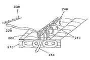
図2は、本発明による継目取付支援装置の半部分220の織物200への取り付け方法を示す。この半部分220は、織物の他端に同様に取り付けられる装置の他の半分と結合する接続要素230の付いた結合縁部を持つ。部品220の取付縁部240は、縁部に沿って横に取り付けられた予め形成されたループ又は螺旋要素を含む。もし装置が織織物であるならば、取付ループ240は装置の糸によって完全に形成されても良く、或いはそれに代わってループは通常当業者に使用される種々の取付方法を使用して取り付けられても良い。
FIG. 2 shows a method of attaching the
織物に装置を取り付けるため、ループ240は、織物の表面の隙間210の中に詰め込まれる。従って、継目取付支援装置は、織物の構造を利用して織物に直接取り付けられる。斯かる構造、例えば螺旋織物では、継目取付支援装置は、“螺旋”又は“ループ”要素240によって織物の表面に取り付けられ得る。“螺旋”又は“ループ”機構は、螺旋織物表面の隙間の中に詰め込まれる。いったんこれらの取付縁部240が挿入されると、ループはピン又は軸棒、糸様の紐又は部材、250が表面に縁部をしっかりと取り付けるために案内される通路を規定する。それ故、ピンがそれを織物に固定するために噛み合わされたループ240と織物の隙間を通って挿入される。これにより、取付縁部が織物から離れることが予防される。固定ピンを取り除くことにより、取付は織物の表面を傷つけることなく簡単に解除され得る。
In order to attach the device to the fabric, the
取付ループ240は、図2で示すように、ピン250により織物に取り付けられることが出来る又はループ240は完全に織物を通り抜けて伸びることが出来て織物200の裏側にはみ出す。そこでピンが取り付けられたループ240を通過できる。
The
ピン糸又は軸棒250は、それが十分に有効である限り織物200の機械に直交する全幅にわたって又はそれのほんの一部だけ若しくは数部分にわたって伸ばすことが出来る。それらが装置のMD糸から形成されようが又は別個のループや螺旋であろうが、取付ループの数は機械上への据付の際織物を引っ張るのに必要な強度を与えるのに十分であるべきであるが、織物本体の中へのループの挿入、又は斯かる領域の中(及び通り抜ける)へのピン糸又は軸棒の挿入を妨げるほど多いことは注記されるべきである。そして又、取付ループの織物の隙間への一対一対応をするべき必要は無い。即ち、もしループの数が織物の隙間の数より大きければすべての取付ループが使用される必要は無い。
The pin thread or
この様式において、装置の各半分は織物の一端近くに独立に取り付けられる。取付縁部はなるべくなら実質上その部分の長さと同じである織物の端からの距離;即ち取付縁部からその部分の結合縁部までの距離で取り付けられる。それで半分ずつが一緒に連結/結合される。取り付けられた部分の結合縁部が一緒に持ち寄られる時、装置は継ぎ合わせのためお互いの近傍に織物の両端を引っ張る。 In this manner, each half of the device is independently attached near one end of the fabric. The attachment edge is preferably attached at a distance from the end of the fabric that is substantially the same as the length of the part; that is, at a distance from the attachment edge to the joining edge of the part. So the halves are connected / coupled together. When the joined edges of the attached parts are brought together, the device pulls both ends of the fabric near each other for seaming.
一旦織物が継ぎ合わされると、軸棒250は、装置の各半分から取り除かれて、それにより今や一緒に継ぎ合わされている織物の両端から、装置を引き離して良い。
Once the fabric is seamed, the
都合良く、織物の両端が継目に近接してある時に、継目取付支援装置は、それにより、より大きな精度と整列とを与える位置に置かれる。そして又ホッチキスで閉じたり縫い込む方法を使用していないので、織物に損傷は起こらない。 Conveniently, when both ends of the fabric are in close proximity to the seam, the seam attachment assist device is thereby placed in a position that provides greater accuracy and alignment. And again, no staples are used to close or sew, so there is no damage to the fabric.
上記に対する改変は、当業者には明白であるが、本発明の範囲を越えて改変された発明をもたらすことはないであろう。 Modifications to the above will be apparent to those skilled in the art, but will not result in a modified invention beyond the scope of the present invention.
例えば、継目取付支援装置が織織物で作られるならば、それは要素240を受け容れる隙間を創る方法で織られるのが良い。これらの隙間又は横方向の不織の帯は簡単にCD糸を織り込まずに形成されても良く、又は水溶性のCD糸が織り込まれて後で溶解されても良く、又はCD糸をほどくことによって機械的に除去され得る。何れの方法でも、これはMD糸だけの領域の何れの側にも織られた領域を持つ織物の平らな帯を残している。この織物はこの不織帯でそれ自身の上に折り畳まれて且つほどかれたMD糸は今やループとして作用する。織られた端部は縫い込まれるか又は一緒にホッチキスで閉じられて且つジッパー材料に取り付けられることが出来る。これは又材料のMDの帯を切り離すことによりそして固形部分の間に挟まれたMD“隙間”帯を残すことにより、不織織物部分にでも施すことが出来る。
For example, if the seam attachment assist device is made of woven fabric, it may be woven in a manner that creates a gap to accept
代案として、もし織物が織若しくは不織であるならば、締め糸が例えばRydin社の特許文献2で説明された方法で織物に固定できる。要素240は、要素240と締め糸と共に形成されるループを通過して軸棒を通すことによりそこに連結できる。継目がしっかりと成った後で、軸棒が除去される。
As an alternative, if the woven fabric is woven or non-woven, the fastening thread can be fixed to the woven fabric, for example, by the method described in US Pat.
斯くして、本発明によりその目標と利点が実現され且つ好適実施例を開示して詳細に述べたが、それらの範囲はそれにより限定されるべきものではなく;むしろ本発明の範囲は、添付した特許請求の範囲によって決定されるべきである。 Thus, while the objectives and advantages of the invention have been realized and described in detail by disclosing preferred embodiments, their scope is not to be limited thereby; rather, the scope of the invention is Should be determined by the appended claims.
100 織物
110 第一端
120 第二端
130 支援装置
140 接続縁部
150 隙間
170 取付縁部
200 織物
210 隙間
220 半部分
230 接続要素
240 取付縁部
250 部材
300 螺旋織物
310 隙間
DESCRIPTION OF
Claims (21)
機械と交差する方向に織物に取り付ける第1取付縁部と、織物の第1端部から機械方向への第1距離と、第1接続縁部とを有する第1部分;及び
機械と交差する方向に織物に取り付ける第2取付縁部と、織物の第2端部から機械方向への第2距離と、第2接続縁部とを有する第2部分;
を有し、
前記第1取付縁部は、前記織物の表面における隙間に適合されその他は前記織物の表面に取り付けられ且つピンヤーン又は軸棒を用いて固定される螺旋又はループ要素を有し;
前記第2取付縁部は、前記織物の表面における隙間に適合されその他は前記織物の表面に取り付けられ且つピンヤーン又は軸棒を用いて固定される螺旋又はループ要素を有し;且つ
前記第1接続縁部は、第2接続縁部に取付可能であり、前記織物の前記第1端部と前記第2端部とは、前記第1接続縁部と前記第2接続縁部とが接続される際前記の取り付けられた第1部分と第2部分とによって継ぎ合わせられることを特徴とする継目支援装置。 A seam support device that supports seaming of paper machine fabrics:
A first portion having a first attachment edge attached to the fabric in a direction intersecting the machine, a first distance in the machine direction from the first end of the fabric, and a first connecting edge; and a direction intersecting the machine A second portion having a second attachment edge attached to the fabric, a second distance in the machine direction from the second end of the fabric, and a second connection edge;
Have
The first attachment edge has a spiral or loop element adapted to a gap in the surface of the fabric and otherwise attached to the surface of the fabric and secured using pin yarns or axles;
The second attachment edge has a spiral or loop element adapted to a gap in the surface of the fabric and otherwise attached to the surface of the fabric and secured using pin yarns or axles; and the first connection The edge can be attached to a second connection edge, and the first end and the second end of the fabric are connected to the first connection edge and the second connection edge. At the same time, the seam support device is joined by the attached first part and second part.
前記の取付縁部及び前記の接続縁部は、平行である
ことを特徴とする請求項1に記載の装置。 The first portion and the second portion have substantially similar dimensions;
The apparatus of claim 1, wherein the mounting edge and the connection edge are parallel.
前記織物の前記第2端部からの前記第2距離は、実質的に前記第2取付縁部から前記第2接続縁部への距離である
ことを特徴とする請求項1に記載の装置。 The first distance from the first end of the fabric is substantially the distance from the first attachment edge to the first connection edge;
The apparatus of claim 1, wherein the second distance from the second end of the fabric is substantially a distance from the second attachment edge to the second connection edge.
機械と交差する方向で、且つ機械方向に前記織物の第1端部から第1距離で、前記継目支援装置の第1部分の第1取付縁部を前記織物に取り付ける第1取付ステップであって、前記第1取付縁部が、前記織物の表面の隙間に螺旋又はループ要素を適合させその他を前記織物の表面に取り付けられ且つピンヤーン又は軸棒を用いて前記の要素を固定して、取り付けられる、第1取付ステップと;
機械と交差する方向で、且つ機械方向に前記織物の第2端部から第1距離で、前記継目支援装置の第2部分の第2取付縁部を前記織物に取り付ける第2取付ステップであって、前記第2取付縁部は、前記織物の表面の隙間に螺旋又はループ要素を適合させその他を前記織物の表面に取り付けられピンヤーン又は軸棒を用いて前記の要素を固定して、取り付けられる、第2取付ステップ;
前記継目支援装置の前記第1部分の第1接続縁部を前記継目支援装置の前記第2部分の第2接続縁部に接続させて前記織物の前記第1端部と前記第2端部とが継ぎ合わせるように共に運搬されることを特徴とする方法。 A method for supporting seaming of paper machine fabrics using a seam support device comprising:
A first attachment step of attaching a first attachment edge of a first portion of the seam support device to the fabric in a direction intersecting the machine and at a first distance from the first end of the fabric in the machine direction; The first attachment edge is attached by fitting a spiral or loop element to the gap in the surface of the fabric and otherwise attaching the element to the surface of the fabric and fixing the element with a pin yarn or shaft rod A first mounting step;
A second attachment step of attaching a second attachment edge of the second portion of the seam support device to the fabric in a direction intersecting the machine and at a first distance from the second end of the fabric in the machine direction; The second attachment edge is attached by fitting a spiral or loop element to a gap in the surface of the fabric and attaching the other to the surface of the fabric and fixing the element using a pin yarn or a shaft rod. Second mounting step;
Connecting the first connection edge of the first portion of the joint support device to the second connection edge of the second portion of the joint support device, and the first end and the second end of the fabric; Characterized in that they are transported together to seam.
前記の取付縁部及び前記の接続縁部は、平行である
ことを特徴とする請求項11に記載の方法。 The first portion and the second portion have substantially similar dimensions;
The method of claim 11, wherein the attachment edge and the connection edge are parallel.
前記織物の前記第2端部からの前記第2距離は、実質的に前記第2取付縁部から前記第2接続縁部への距離である
ことを特徴とする請求項11に記載の方法。 The first distance from the first end of the fabric is substantially the distance from the first attachment edge to the first connection edge;
The method of claim 11, wherein the second distance from the second end of the fabric is substantially a distance from the second attachment edge to the second connection edge.
Applications Claiming Priority (2)
| Application Number | Priority Date | Filing Date | Title |
|---|---|---|---|
| US10/331,021 US7086128B2 (en) | 2002-12-27 | 2002-12-27 | Seam assist attachment device |
| PCT/US2003/036756 WO2004061206A1 (en) | 2002-12-27 | 2003-11-17 | Seam assist attachment device |
Publications (2)
| Publication Number | Publication Date |
|---|---|
| JP2006512500A true JP2006512500A (en) | 2006-04-13 |
| JP2006512500A5 JP2006512500A5 (en) | 2010-08-19 |
Family
ID=32710829
Family Applications (1)
| Application Number | Title | Priority Date | Filing Date |
|---|---|---|---|
| JP2004565009A Pending JP2006512500A (en) | 2002-12-27 | 2003-11-17 | Joint installation support device |
Country Status (18)
| Country | Link |
|---|---|
| US (1) | US7086128B2 (en) |
| EP (1) | EP1576231B1 (en) |
| JP (1) | JP2006512500A (en) |
| KR (1) | KR20050088334A (en) |
| CN (1) | CN100385066C (en) |
| AT (1) | ATE526448T1 (en) |
| AU (1) | AU2003297286C1 (en) |
| BR (1) | BRPI0317632B1 (en) |
| CA (1) | CA2505199C (en) |
| ES (1) | ES2369267T3 (en) |
| MX (1) | MXPA05005779A (en) |
| NO (1) | NO20053622L (en) |
| NZ (1) | NZ539759A (en) |
| PT (1) | PT1576231E (en) |
| RU (1) | RU2339754C2 (en) |
| TW (1) | TWI306131B (en) |
| WO (1) | WO2004061206A1 (en) |
| ZA (1) | ZA200503599B (en) |
Families Citing this family (3)
| Publication number | Priority date | Publication date | Assignee | Title |
|---|---|---|---|---|
| CA2762349A1 (en) * | 2011-12-16 | 2013-06-16 | Allan R. MANNINEN | Multi-pin nonwoven seaming element |
| US11332879B2 (en) | 2018-10-10 | 2022-05-17 | Astenjohnson International, Inc. | Pintle insertion tool |
| CN113250000B (en) * | 2021-06-09 | 2023-12-12 | 安徽华辰造纸网股份有限公司 | Connecting ring for papermaking dry net and threading method between papermaking dry nets |
Citations (6)
| Publication number | Priority date | Publication date | Assignee | Title |
|---|---|---|---|---|
| US4567077A (en) * | 1980-11-13 | 1986-01-28 | Cofpa | Papermaker's fabric constituted by plastic spirals |
| JPH01106596U (en) * | 1988-01-11 | 1989-07-18 | ||
| EP0489557A1 (en) * | 1990-12-06 | 1992-06-10 | Scapa Group Plc | Spiral shrink sleeve |
| WO1997020105A1 (en) * | 1995-11-30 | 1997-06-05 | Albany International Corp. | Laminated clothing, as well as method and blank for manufacturing the same |
| JPH1037093A (en) * | 1997-04-24 | 1998-02-10 | Shikibo Ltd | Method for inserting joining core wire into joint part of papermaking cloth |
| JPH10237789A (en) * | 1997-02-24 | 1998-09-08 | Shikibo Ltd | Joint-connecting tool for drier canvas in paper machine |
Family Cites Families (14)
| Publication number | Priority date | Publication date | Assignee | Title |
|---|---|---|---|---|
| US3581348A (en) * | 1970-07-27 | 1971-06-01 | Huyck Corp | Seams for papermaking clothing |
| GB1522801A (en) * | 1975-01-07 | 1978-08-31 | Jwi Ltd | Fabric and a method of joining the opposite ends of such a fabric together to form an endless belt |
| GB8630243D0 (en) | 1986-12-18 | 1987-01-28 | Scapa Porritt Ltd | Dryer fabric seaming |
| FR2611764B1 (en) * | 1987-03-02 | 1989-05-05 | Cofpa | PROCESS FOR THE MANUFACTURE OF A FELT WITH FLAP |
| FR2628453B1 (en) | 1988-03-08 | 1990-11-16 | Cofpa | METHOD OF LAYING A FABRIC AROUND A CYLINDER AND PRE-TENSIONING DEVICE FOR IMPLEMENTING THE METHOD |
| US5015220A (en) * | 1988-08-03 | 1991-05-14 | Tamfelt, Inc. | Seam for work fabric and method of manufacture thereof |
| GB8825870D0 (en) * | 1988-11-04 | 1988-12-07 | Scapa Group Plc | Jointing of fabric ends |
| US4972561A (en) * | 1989-12-26 | 1990-11-27 | Niagara Lockport Industries Inc. | Method of producing an angled pin seam in a papermakers felt |
| GB9112071D0 (en) * | 1991-06-05 | 1991-07-24 | Scapa Group Plc | Belt seaming |
| SE504119C2 (en) * | 1995-03-27 | 1996-11-18 | Nordiskafilt Ab Albany | Machine trim with stitch and spiral for use in such a stitch |
| GB9519837D0 (en) * | 1995-09-29 | 1995-11-29 | Scapa Group Plc | Dryer fabric seaming |
| US5632701A (en) * | 1995-10-31 | 1997-05-27 | Beltservice Corporation | Industrial belt splice assembly |
| US5732749A (en) * | 1997-02-14 | 1998-03-31 | Albany International Corp. | Pin seam for laminated integrally woven papermaker's fabric |
| US6194331B1 (en) * | 1998-03-05 | 2001-02-27 | Albany International Corp. | Flow-resistant material additions to double-seam on machine-seamable fabrics |
-
2002
- 2002-12-27 US US10/331,021 patent/US7086128B2/en active Active
-
2003
- 2003-11-17 ES ES03814625T patent/ES2369267T3/en not_active Expired - Lifetime
- 2003-11-17 NZ NZ539759A patent/NZ539759A/en unknown
- 2003-11-17 BR BRPI0317632A patent/BRPI0317632B1/en active IP Right Grant
- 2003-11-17 MX MXPA05005779A patent/MXPA05005779A/en active IP Right Grant
- 2003-11-17 CA CA2505199A patent/CA2505199C/en not_active Expired - Lifetime
- 2003-11-17 KR KR1020057012036A patent/KR20050088334A/en not_active Application Discontinuation
- 2003-11-17 WO PCT/US2003/036756 patent/WO2004061206A1/en active Application Filing
- 2003-11-17 JP JP2004565009A patent/JP2006512500A/en active Pending
- 2003-11-17 AU AU2003297286A patent/AU2003297286C1/en not_active Ceased
- 2003-11-17 RU RU2005123806/12A patent/RU2339754C2/en not_active IP Right Cessation
- 2003-11-17 ZA ZA200503599A patent/ZA200503599B/en unknown
- 2003-11-17 PT PT03814625T patent/PT1576231E/en unknown
- 2003-11-17 EP EP03814625A patent/EP1576231B1/en not_active Expired - Lifetime
- 2003-11-17 AT AT03814625T patent/ATE526448T1/en active
- 2003-11-17 CN CNB2003801059411A patent/CN100385066C/en not_active Expired - Fee Related
- 2003-11-26 TW TW092133196A patent/TWI306131B/en not_active IP Right Cessation
-
2005
- 2005-07-26 NO NO20053622A patent/NO20053622L/en not_active Application Discontinuation
Patent Citations (7)
| Publication number | Priority date | Publication date | Assignee | Title |
|---|---|---|---|---|
| US4567077A (en) * | 1980-11-13 | 1986-01-28 | Cofpa | Papermaker's fabric constituted by plastic spirals |
| JPH01106596U (en) * | 1988-01-11 | 1989-07-18 | ||
| EP0489557A1 (en) * | 1990-12-06 | 1992-06-10 | Scapa Group Plc | Spiral shrink sleeve |
| WO1997020105A1 (en) * | 1995-11-30 | 1997-06-05 | Albany International Corp. | Laminated clothing, as well as method and blank for manufacturing the same |
| JPH10513511A (en) * | 1995-11-30 | 1998-12-22 | アルバニー、インターナショナル、コーポレイション | Laminate closing and method and semi-finished product for producing laminate closing |
| JPH10237789A (en) * | 1997-02-24 | 1998-09-08 | Shikibo Ltd | Joint-connecting tool for drier canvas in paper machine |
| JPH1037093A (en) * | 1997-04-24 | 1998-02-10 | Shikibo Ltd | Method for inserting joining core wire into joint part of papermaking cloth |
Also Published As
| Publication number | Publication date |
|---|---|
| ES2369267T3 (en) | 2011-11-29 |
| NO20053622L (en) | 2005-07-26 |
| EP1576231B1 (en) | 2011-09-28 |
| ZA200503599B (en) | 2007-12-27 |
| AU2003297286B2 (en) | 2009-03-12 |
| ATE526448T1 (en) | 2011-10-15 |
| RU2005123806A (en) | 2006-01-27 |
| EP1576231A1 (en) | 2005-09-21 |
| WO2004061206A1 (en) | 2004-07-22 |
| CA2505199A1 (en) | 2004-07-22 |
| RU2339754C2 (en) | 2008-11-27 |
| TW200420801A (en) | 2004-10-16 |
| US7086128B2 (en) | 2006-08-08 |
| AU2003297286A1 (en) | 2004-07-29 |
| CA2505199C (en) | 2011-06-21 |
| KR20050088334A (en) | 2005-09-05 |
| TWI306131B (en) | 2009-02-11 |
| BR0317632A (en) | 2005-11-29 |
| NZ539759A (en) | 2006-04-28 |
| CN1726315A (en) | 2006-01-25 |
| CN100385066C (en) | 2008-04-30 |
| AU2003297286C1 (en) | 2009-09-17 |
| BRPI0317632B1 (en) | 2015-10-13 |
| PT1576231E (en) | 2011-10-12 |
| US20040224105A1 (en) | 2004-11-11 |
| MXPA05005779A (en) | 2005-08-16 |
Similar Documents
| Publication | Publication Date | Title |
|---|---|---|
| JP5603435B2 (en) | Method and apparatus for installing industrial fabric with seams | |
| ZA200503238B (en) | Multi-tier rope harness for installing a fabric into a paper-making machine | |
| JP2006512500A (en) | Joint installation support device | |
| JP4153205B2 (en) | Equipment for laying fabrics on paper machines | |
| JP2006512500A5 (en) | ||
| KR100980634B1 (en) | Pull-on leader | |
| JP4768625B2 (en) | Transparent seam spiral | |
| US5033618A (en) | Installation cable unwinder | |
| JP2005264402A (en) | Seam felt equipped with auxiliary tool for joining and method for attaching seam felt to papermaking machine |
Legal Events
| Date | Code | Title | Description |
|---|---|---|---|
| A521 | Request for written amendment filed |
Free format text: JAPANESE INTERMEDIATE CODE: A523 Effective date: 20061005 |
|
| A621 | Written request for application examination |
Free format text: JAPANESE INTERMEDIATE CODE: A621 Effective date: 20061005 |
|
| A977 | Report on retrieval |
Free format text: JAPANESE INTERMEDIATE CODE: A971007 Effective date: 20090819 |
|
| A131 | Notification of reasons for refusal |
Free format text: JAPANESE INTERMEDIATE CODE: A131 Effective date: 20090828 |
|
| A521 | Request for written amendment filed |
Free format text: JAPANESE INTERMEDIATE CODE: A523 Effective date: 20091127 |
|
| A131 | Notification of reasons for refusal |
Free format text: JAPANESE INTERMEDIATE CODE: A131 Effective date: 20100402 |
|
| RD02 | Notification of acceptance of power of attorney |
Free format text: JAPANESE INTERMEDIATE CODE: A7422 Effective date: 20100623 |
|
| A521 | Request for written amendment filed |
Free format text: JAPANESE INTERMEDIATE CODE: A523 Effective date: 20100702 |
|
| A524 | Written submission of copy of amendment under article 19 pct |
Free format text: JAPANESE INTERMEDIATE CODE: A524 Effective date: 20100702 |
|
| A131 | Notification of reasons for refusal |
Free format text: JAPANESE INTERMEDIATE CODE: A131 Effective date: 20110105 |
|
| A02 | Decision of refusal |
Free format text: JAPANESE INTERMEDIATE CODE: A02 Effective date: 20110705 |