JP2006512100A - Vascular exclusion catheter - Google Patents
Vascular exclusion catheter Download PDFInfo
- Publication number
- JP2006512100A JP2006512100A JP2003567486A JP2003567486A JP2006512100A JP 2006512100 A JP2006512100 A JP 2006512100A JP 2003567486 A JP2003567486 A JP 2003567486A JP 2003567486 A JP2003567486 A JP 2003567486A JP 2006512100 A JP2006512100 A JP 2006512100A
- Authority
- JP
- Japan
- Prior art keywords
- dilator
- profile state
- catheter
- expansion assembly
- body conduit
- Prior art date
- Legal status (The legal status is an assumption and is not a legal conclusion. Google has not performed a legal analysis and makes no representation as to the accuracy of the status listed.)
- Pending
Links
- 230000007717 exclusion Effects 0.000 title claims abstract description 23
- 230000002792 vascular Effects 0.000 title description 2
- 239000012530 fluid Substances 0.000 claims abstract description 54
- 238000000034 method Methods 0.000 claims abstract description 28
- 210000001124 body fluid Anatomy 0.000 claims abstract description 8
- 238000003780 insertion Methods 0.000 claims abstract description 6
- 230000037431 insertion Effects 0.000 claims abstract description 6
- 239000010839 body fluid Substances 0.000 claims abstract description 5
- 238000000926 separation method Methods 0.000 claims abstract description 5
- 210000004204 blood vessel Anatomy 0.000 claims description 16
- 230000017531 blood circulation Effects 0.000 claims description 9
- 239000008280 blood Substances 0.000 claims description 7
- 210000004369 blood Anatomy 0.000 claims description 7
- 239000000463 material Substances 0.000 claims description 7
- 238000007789 sealing Methods 0.000 claims description 3
- 230000002093 peripheral effect Effects 0.000 claims 5
- 238000005452 bending Methods 0.000 claims 1
- 238000004519 manufacturing process Methods 0.000 claims 1
- 238000007667 floating Methods 0.000 description 15
- 210000003813 thumb Anatomy 0.000 description 5
- 238000013459 approach Methods 0.000 description 4
- 230000003872 anastomosis Effects 0.000 description 3
- 210000003462 vein Anatomy 0.000 description 3
- 238000001574 biopsy Methods 0.000 description 2
- 210000004351 coronary vessel Anatomy 0.000 description 2
- 230000006378 damage Effects 0.000 description 2
- 239000003814 drug Substances 0.000 description 2
- 239000013536 elastomeric material Substances 0.000 description 2
- WQZGKKKJIJFFOK-GASJEMHNSA-N Glucose Chemical compound OC[C@H]1OC(O)[C@H](O)[C@@H](O)[C@@H]1O WQZGKKKJIJFFOK-GASJEMHNSA-N 0.000 description 1
- 208000032382 Ischaemic stroke Diseases 0.000 description 1
- 230000009471 action Effects 0.000 description 1
- 239000004019 antithrombin Substances 0.000 description 1
- 210000000709 aorta Anatomy 0.000 description 1
- 210000001367 artery Anatomy 0.000 description 1
- 230000001174 ascending effect Effects 0.000 description 1
- 230000015572 biosynthetic process Effects 0.000 description 1
- 230000000740 bleeding effect Effects 0.000 description 1
- 230000002490 cerebral effect Effects 0.000 description 1
- 230000008859 change Effects 0.000 description 1
- 238000006243 chemical reaction Methods 0.000 description 1
- 239000003795 chemical substances by application Substances 0.000 description 1
- 239000011248 coating agent Substances 0.000 description 1
- 238000000576 coating method Methods 0.000 description 1
- 238000004891 communication Methods 0.000 description 1
- 238000010276 construction Methods 0.000 description 1
- 229910003460 diamond Inorganic materials 0.000 description 1
- 239000010432 diamond Substances 0.000 description 1
- 229940079593 drug Drugs 0.000 description 1
- 210000003811 finger Anatomy 0.000 description 1
- 230000000977 initiatory effect Effects 0.000 description 1
- 208000014674 injury Diseases 0.000 description 1
- 239000002085 irritant Substances 0.000 description 1
- 231100000021 irritant Toxicity 0.000 description 1
- 210000003141 lower extremity Anatomy 0.000 description 1
- 230000007246 mechanism Effects 0.000 description 1
- 238000012986 modification Methods 0.000 description 1
- 230000004048 modification Effects 0.000 description 1
- 230000035515 penetration Effects 0.000 description 1
- 230000008569 process Effects 0.000 description 1
- 230000008439 repair process Effects 0.000 description 1
- 238000002271 resection Methods 0.000 description 1
- 210000003752 saphenous vein Anatomy 0.000 description 1
- 238000007790 scraping Methods 0.000 description 1
- 239000007787 solid Substances 0.000 description 1
- 230000009885 systemic effect Effects 0.000 description 1
- 229940124597 therapeutic agent Drugs 0.000 description 1
- 230000001225 therapeutic effect Effects 0.000 description 1
- 239000012815 thermoplastic material Substances 0.000 description 1
- 230000002885 thrombogenetic effect Effects 0.000 description 1
- 230000007704 transition Effects 0.000 description 1
- 230000008733 trauma Effects 0.000 description 1
- 230000000472 traumatic effect Effects 0.000 description 1
- 238000011144 upstream manufacturing Methods 0.000 description 1
- 210000005166 vasculature Anatomy 0.000 description 1
- 210000001835 viscera Anatomy 0.000 description 1
Images


Classifications
-
- A—HUMAN NECESSITIES
- A61—MEDICAL OR VETERINARY SCIENCE; HYGIENE
- A61B—DIAGNOSIS; SURGERY; IDENTIFICATION
- A61B17/00—Surgical instruments, devices or methods, e.g. tourniquets
- A61B17/12—Surgical instruments, devices or methods, e.g. tourniquets for ligaturing or otherwise compressing tubular parts of the body, e.g. blood vessels, umbilical cord
- A61B17/12022—Occluding by internal devices, e.g. balloons or releasable wires
- A61B17/12027—Type of occlusion
- A61B17/12036—Type of occlusion partial occlusion
-
- A—HUMAN NECESSITIES
- A61—MEDICAL OR VETERINARY SCIENCE; HYGIENE
- A61B—DIAGNOSIS; SURGERY; IDENTIFICATION
- A61B17/00—Surgical instruments, devices or methods, e.g. tourniquets
- A61B17/12—Surgical instruments, devices or methods, e.g. tourniquets for ligaturing or otherwise compressing tubular parts of the body, e.g. blood vessels, umbilical cord
- A61B17/12022—Occluding by internal devices, e.g. balloons or releasable wires
- A61B17/12027—Type of occlusion
- A61B17/1204—Type of occlusion temporary occlusion
- A61B17/12045—Type of occlusion temporary occlusion double occlusion, e.g. during anastomosis
-
- A—HUMAN NECESSITIES
- A61—MEDICAL OR VETERINARY SCIENCE; HYGIENE
- A61B—DIAGNOSIS; SURGERY; IDENTIFICATION
- A61B17/00—Surgical instruments, devices or methods, e.g. tourniquets
- A61B17/12—Surgical instruments, devices or methods, e.g. tourniquets for ligaturing or otherwise compressing tubular parts of the body, e.g. blood vessels, umbilical cord
- A61B17/12022—Occluding by internal devices, e.g. balloons or releasable wires
- A61B17/12099—Occluding by internal devices, e.g. balloons or releasable wires characterised by the location of the occluder
- A61B17/12109—Occluding by internal devices, e.g. balloons or releasable wires characterised by the location of the occluder in a blood vessel
-
- A—HUMAN NECESSITIES
- A61—MEDICAL OR VETERINARY SCIENCE; HYGIENE
- A61B—DIAGNOSIS; SURGERY; IDENTIFICATION
- A61B17/00—Surgical instruments, devices or methods, e.g. tourniquets
- A61B17/12—Surgical instruments, devices or methods, e.g. tourniquets for ligaturing or otherwise compressing tubular parts of the body, e.g. blood vessels, umbilical cord
- A61B17/12022—Occluding by internal devices, e.g. balloons or releasable wires
- A61B17/12131—Occluding by internal devices, e.g. balloons or releasable wires characterised by the type of occluding device
- A61B17/12136—Balloons
-
- A—HUMAN NECESSITIES
- A61—MEDICAL OR VETERINARY SCIENCE; HYGIENE
- A61B—DIAGNOSIS; SURGERY; IDENTIFICATION
- A61B17/00—Surgical instruments, devices or methods, e.g. tourniquets
- A61B17/12—Surgical instruments, devices or methods, e.g. tourniquets for ligaturing or otherwise compressing tubular parts of the body, e.g. blood vessels, umbilical cord
- A61B17/12022—Occluding by internal devices, e.g. balloons or releasable wires
- A61B17/12131—Occluding by internal devices, e.g. balloons or releasable wires characterised by the type of occluding device
- A61B17/12168—Occluding by internal devices, e.g. balloons or releasable wires characterised by the type of occluding device having a mesh structure
- A61B17/12172—Occluding by internal devices, e.g. balloons or releasable wires characterised by the type of occluding device having a mesh structure having a pre-set deployed three-dimensional shape
-
- A—HUMAN NECESSITIES
- A61—MEDICAL OR VETERINARY SCIENCE; HYGIENE
- A61M—DEVICES FOR INTRODUCING MEDIA INTO, OR ONTO, THE BODY; DEVICES FOR TRANSDUCING BODY MEDIA OR FOR TAKING MEDIA FROM THE BODY; DEVICES FOR PRODUCING OR ENDING SLEEP OR STUPOR
- A61M25/00—Catheters; Hollow probes
- A61M25/10—Balloon catheters
- A61M25/1011—Multiple balloon catheters
-
- A—HUMAN NECESSITIES
- A61—MEDICAL OR VETERINARY SCIENCE; HYGIENE
- A61M—DEVICES FOR INTRODUCING MEDIA INTO, OR ONTO, THE BODY; DEVICES FOR TRANSDUCING BODY MEDIA OR FOR TAKING MEDIA FROM THE BODY; DEVICES FOR PRODUCING OR ENDING SLEEP OR STUPOR
- A61M29/00—Dilators with or without means for introducing media, e.g. remedies
- A61M29/02—Dilators made of swellable material
-
- A—HUMAN NECESSITIES
- A61—MEDICAL OR VETERINARY SCIENCE; HYGIENE
- A61B—DIAGNOSIS; SURGERY; IDENTIFICATION
- A61B17/00—Surgical instruments, devices or methods, e.g. tourniquets
- A61B17/12—Surgical instruments, devices or methods, e.g. tourniquets for ligaturing or otherwise compressing tubular parts of the body, e.g. blood vessels, umbilical cord
- A61B17/12022—Occluding by internal devices, e.g. balloons or releasable wires
- A61B2017/12127—Double occlusion, e.g. for creating blood-free anastomosis site
-
- A—HUMAN NECESSITIES
- A61—MEDICAL OR VETERINARY SCIENCE; HYGIENE
- A61M—DEVICES FOR INTRODUCING MEDIA INTO, OR ONTO, THE BODY; DEVICES FOR TRANSDUCING BODY MEDIA OR FOR TAKING MEDIA FROM THE BODY; DEVICES FOR PRODUCING OR ENDING SLEEP OR STUPOR
- A61M25/00—Catheters; Hollow probes
- A61M25/10—Balloon catheters
- A61M2025/1043—Balloon catheters with special features or adapted for special applications
- A61M2025/1081—Balloon catheters with special features or adapted for special applications having sheaths or the like for covering the balloon but not forming a permanent part of the balloon, e.g. retractable, dissolvable or tearable sheaths
-
- A—HUMAN NECESSITIES
- A61—MEDICAL OR VETERINARY SCIENCE; HYGIENE
- A61M—DEVICES FOR INTRODUCING MEDIA INTO, OR ONTO, THE BODY; DEVICES FOR TRANSDUCING BODY MEDIA OR FOR TAKING MEDIA FROM THE BODY; DEVICES FOR PRODUCING OR ENDING SLEEP OR STUPOR
- A61M25/00—Catheters; Hollow probes
- A61M25/10—Balloon catheters
- A61M25/1002—Balloon catheters characterised by balloon shape
Landscapes
- Health & Medical Sciences (AREA)
- Life Sciences & Earth Sciences (AREA)
- Surgery (AREA)
- Heart & Thoracic Surgery (AREA)
- Animal Behavior & Ethology (AREA)
- Veterinary Medicine (AREA)
- Engineering & Computer Science (AREA)
- Public Health (AREA)
- Biomedical Technology (AREA)
- General Health & Medical Sciences (AREA)
- Vascular Medicine (AREA)
- Reproductive Health (AREA)
- Nuclear Medicine, Radiotherapy & Molecular Imaging (AREA)
- Medical Informatics (AREA)
- Molecular Biology (AREA)
- Hematology (AREA)
- Anesthesiology (AREA)
- Pulmonology (AREA)
- Biophysics (AREA)
- Child & Adolescent Psychology (AREA)
- Media Introduction/Drainage Providing Device (AREA)
Abstract
流体制御装置(10)が体内導管内に配置されるようになっており、流体制御装置は、体内導管内の体液の流れを制御する。スリーブ(60)が、体液の流れを容易にする流路を構成する第1の表面及び流路から密閉された除外チャンバを構成する第2の表面を有する分離壁を備えている。種々の拡張器(46,48)が、密封体を流体制御装置の挿入を容易にするロープロフィール状態と流路及び除外チャンバ(67)を構成するハイプロフィール状態との間で移動させる特性を有する。拡張器(46,48)は、骨格構造のもの、膨らまし可能なもの又は多孔性のものであるのがよい。かかる流体制御装置と関連した方法は、拡張組立体を拡張させて壁を挿入可能なロープロフィール状態から壁が流路及び除外キャビティを構成するハイプロフィール状態に移動させる段階を有する。A fluid control device (10) is disposed within the body conduit, and the fluid control device controls the flow of body fluid within the body conduit. The sleeve (60) includes a separation wall having a first surface that forms a flow path that facilitates the flow of bodily fluids, and a second surface that forms an exclusion chamber sealed from the flow path. Various dilators (46, 48) have the property of moving the seal between a low profile state that facilitates the insertion of the fluid control device and a high profile state that constitutes the flow path and exclusion chamber (67). . The dilators (46, 48) may be skeletal, inflatable or porous. A method associated with such a fluid control device includes expanding the expansion assembly to move the wall from a low profile state in which the wall can be inserted to a high profile state in which the wall constitutes the flow path and exclusion cavity.
Description
本発明は、一般に、体内導管内の流れを少なくとも部分的に止める装置及び方法に関する。 The present invention relates generally to an apparatus and method for at least partially stopping flow in a body conduit.
体内導管は一般に、体内の或る1つの場所から体内の別の場所への流体の流れを可能にする。これら流体導管の代表例は、心臓と体内の器官との間での血液の流れをもたらす血管系を構成する動脈及び静脈である。特定の処置において血管に接近することが必要な場合、流体の流れは、接近穴を通して導管から流れ出ることが予想可能である。この結果、流体、例えば血液が失われるだけでなく、流体が全体的な手術環境に侵入する。冠動脈バイパス移植(CABG)術において、このような一つの処置では、伏在静脈を下肢から摘出し、その静脈を上行静脈に連結することが望ましい。 Body conduits generally allow fluid flow from one location in the body to another location in the body. Typical examples of these fluid conduits are the arteries and veins that make up the vasculature that provides the flow of blood between the heart and internal organs. If it is necessary to access the blood vessel in a particular procedure, fluid flow can be expected to flow out of the conduit through the access hole. As a result, not only is fluid lost, such as blood, but fluid also enters the overall surgical environment. In a coronary artery bypass graft (CABG) procedure, in one such procedure, it is desirable to remove the saphenous vein from the lower limb and connect the vein to the ascending vein.
従来、外科医は、導管又は血管を通る血液の流れを止めるために閉塞カテーテルを用いていた。このカテーテルは、膨らまされると、血管内の血液の流れを完全に止める球形バルーンを備えるものであった。特に、血管の場合、これは望ましくない。というのは、血液の中断することのない流れが身体の組織を維持するうえで必要だからである。
完全閉塞を避けるため、血液を手術部位の上流側で完全に除き、手術部位の下流側に導入する別の処置が開発された。“オン・ポンプ:on-pump (体外循環心停止下)”冠動脈バイパス移植(OPCABG)術と通称されているこの処置では、連続した妨げられない心拍動がある。それにもかかわらず、この処置では、有用な近位吻合部を形成するために大動脈切除術からの血液の流れの管理が必要である。この理由は、多くのCAPD処置が依然として“オフ・ポンプ:off-pump(心拍動下)”で実行されるからである。
Traditionally, surgeons have used occlusion catheters to stop blood flow through a conduit or blood vessel. The catheter was equipped with a spherical balloon that completely stopped the blood flow in the blood vessel when inflated. This is undesirable especially in the case of blood vessels. This is because an uninterrupted flow of blood is necessary to maintain body tissue.
To avoid complete occlusion, another procedure has been developed that completely removes blood upstream of the surgical site and introduces it downstream of the surgical site. In this procedure, commonly referred to as “on-pump” coronary artery bypass graft (OPCABG), there is a continuous unhindered heart beat. Nevertheless, this procedure requires the management of blood flow from the aorticectomy to form a useful proximal anastomosis. This is because many CAPD procedures are still performed “off-pump”.
現在、大動脈切除術から血液の流れの管理を達成するための外科医の主要なツールは、部分閉塞クランプ(Partial Occluding Clamp )である。これら“オフ・ポンプ:off-pump”処置では、部分閉塞クランプは、導管又は血管に外部から係合し、それにより血管の僅かな部分を目下の流体の流れから隔離するために用いられる場合が多い。 Currently, the surgeon's primary tool for achieving blood flow management from aortic resection is the Partial Occluding Clamp. In these “off-pump” procedures, a partial occlusion clamp may be used to externally engage a conduit or vessel, thereby isolating a small portion of the vessel from the current fluid flow. Many.
部分閉塞クランプは使用法が比較的簡単であるが、多くの人により外傷性が非常に高いと考えられている。その使用法は、局所的結果と全身的な結果の両方において、二次的合併症、例えばプラークの破壊及びその結果としての一時的虚血性発作又は大脳血管事故を引き起こすことが報告されている。部分閉塞クランプは又、そのジョーを大動脈に取り付けるだけでなくそのクランプハンドルを手術野内に配置した状態で処置領域の大部分を費やす。 Partial occlusion clamps are relatively easy to use, but many people are considered very traumatic. Its use has been reported to cause secondary complications such as plaque destruction and consequent temporary ischemic stroke or cerebral vascular accidents in both local and systemic results. Partial occlusion clamps also spend most of the treatment area with the jaws attached to the aorta and the clamp handle placed in the surgical field.
従来技術のこれら欠点は、導管を通る流体の流れを維持すると共にこの流体の流れから導管の一部を遮蔽又は除外(exclude )できる拡張組立体を備えたカテーテルに関する本発明によって解決される。重要なこととして、このカテーテルは、非侵襲性であり、外科的環境において広いスペースを必要としないよう管腔内的に挿入される。カテーテルの拡張組立体は、導管内の流体の流れを維持すると共にこの流体の流れから導管の一部を隔離する除外キャビティを作ることができる。 These shortcomings of the prior art are solved by the present invention relating to a catheter with an expansion assembly that can maintain fluid flow through the conduit and shield or exclude portions of the conduit from the fluid flow. Importantly, the catheter is non-invasive and is inserted intraluminally so that it does not require large space in the surgical environment. The catheter expansion assembly can create an exclusion cavity that maintains fluid flow in the conduit and isolates a portion of the conduit from the fluid flow.
本発明の一つの観点では、流体制御装置が、体内導管中の体液の流れを制御するために体内導管内に配置されるようになっている。この装置は、第1の表面と、第1の表面と反対側の第2の表面とを備えた分離壁を有する。壁の第1の表面は、体内導管内の体液の流れを容易にする流路を構成し、壁の第2の表面は、流路及び体内導管を通る流体の流れから遮断された除外チャンバを構成する。 In one aspect of the invention, a fluid control device is disposed within the body conduit for controlling the flow of body fluid in the body conduit. The device has a separation wall with a first surface and a second surface opposite the first surface. The first surface of the wall constitutes a flow path that facilitates the flow of bodily fluid within the body conduit, and the second surface of the wall defines an exclusion chamber that is shielded from the flow of fluid through the flow path and the body conduit. Constitute.
本発明の別の観点では、カテーテルが、体内導管内に配置されるようになっており、このカテーテルは、軸線に沿って近位端部と遠位端部との間に延びるシャフトを有する。拡張管が、シャフトの遠位端部のところに設けられており、この拡張組立体は、ハイプロフィール状態とロープロフィール状態との間で動くことができる第1の拡張器を有する。第2の拡張器が、拡張組立体に含まれており、この第2の拡張器は、全体として第1の拡張器とは別個独立にハイプロフィール状態とロープロフィール状態との間で動くことができる。スリーブが、第1の拡張器及び第2の拡張器によってハイプロフィール状態とロープロフィール状態との間で運搬される。 In another aspect of the invention, a catheter is adapted for placement within a body conduit, the catheter having a shaft extending between a proximal end and a distal end along an axis. An expansion tube is provided at the distal end of the shaft, the expansion assembly having a first dilator that is movable between a high profile state and a low profile state. A second dilator is included in the expansion assembly, and the second dilator can move between a high profile state and a low profile state independently of the first dilator as a whole. it can. A sleeve is carried between a high profile state and a low profile state by the first dilator and the second dilator.
本発明の別の観点では、カテーテルが、体内導管内に配置されるようになっている。このカテーテルは、シャフトと、シャフトの遠位端部のところに設けられた拡張組立体とを有する。拡張組立体は、体内導管内への拡張組立体の挿入を容易にするロープロフィール状態及び体内導管内での拡張組立体の動作を容易にするハイプロフィール状態を有する。シャフトは、外側部材と入れ子式の関係をなして設けられた内側部材を有する。拡張器が、外側部材によって支持された第1の端部及び内側部材によって支持された第2の端部を備える。これら第1の端部と第2の端部は、拡張器がハイプロフィール状態にあるとき、全体として互いに近接した関係をなし、第1の端部と第2の端部は、拡張器がロープロフィール状態にあるとき、全体として互いに間隔を置いた関係をなす。
本発明の別の特徴では、拡張組立体は、ハイプロフィール状態に動くよう膨らまし可能なバルーンを有する。この状態では、バルーンの第1の部分は、体内導管内の流体の流れを容易にする流体流路を構成する。
In another aspect of the invention, a catheter is adapted for placement within a body conduit. The catheter has a shaft and an expansion assembly provided at the distal end of the shaft. The expansion assembly has a low profile state that facilitates insertion of the expansion assembly into the body conduit and a high profile state that facilitates operation of the expansion assembly within the body conduit. The shaft has an inner member provided in a telescoping relationship with the outer member. The dilator comprises a first end supported by the outer member and a second end supported by the inner member. The first end and the second end are generally in close proximity to each other when the dilator is in the high profile state, and the first end and the second end are When in profile, they are generally spaced from one another.
In another aspect of the invention, the expansion assembly includes a balloon that is inflatable to move to a high profile state. In this state, the first portion of the balloon constitutes a fluid flow path that facilitates fluid flow within the body conduit.
本発明は、別の観点では、血管を通る血液の流れを止めないで血管の所定の領域に沿う血液の流れを制限する血管内方法を提供する。この方法は、ハイプロフィール状態とロープロフィール状態との間で動くことができる壁を備えた拡張組立体を有するカテーテルを用意する段階を有する。拡張組立体をロープロフィール状態で手術部位まで血管内へ挿入する。手術部位では、拡張組立体を拡張して壁をハイプロフィール状態に動かす段階とを有し、壁はハイプロフィール状態において、血管の所定の領域と協働して血管内の血液の流れから隔離された除外キャビティを構成する。
本発明の上記特徴及び利点並びに他の特徴及び利点を本発明の好ましい実施形態及び添付の図面を参照して更に説明する。
The present invention, in another aspect, provides an intravascular method for restricting blood flow along a predetermined region of a blood vessel without stopping the flow of blood through the blood vessel. The method includes providing a catheter having an expansion assembly with a wall that can move between a high profile state and a low profile state. The expansion assembly is inserted into the blood vessel in a low profile state up to the surgical site. At the surgical site, expanding the expansion assembly to move the wall to a high profile state, wherein the wall is isolated from the blood flow in the blood vessel in cooperation with a predetermined region of the blood vessel in the high profile state. Constitute an excluded cavity.
These and other features and advantages of the present invention will be further described with reference to preferred embodiments of the invention and the accompanying drawings.
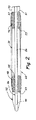
除外カテーテル(エクスクルージョン・カテーテル:exclusion catheter)装置が、図1に示されており、この除外カテーテル装置は、全体が符号10で指示されている。この特定の装置10は、体内導管のセグメントを除外すると共に導管の残部を通る流れを容易にするようになっている。装置10は、ハンドピース22及び軸線方向に可動のサム又は指動スライダ24を備えたハンドル組立体20を有している。サムスライダ24は、管組立体31の細長い内側部材26に結合されている。好ましい実施形態では、内側の細長い部材26は、中空コア又はルーメン27を備えた管から成る。変形例として、内側の細長い部材26は、中実コアを有していてもよく、かくして、例えばワイヤから成るものであってよい。
An exclusion catheter device is shown in FIG. 1 and is generally designated 10. This
ハンドル組立体20は、管組立体31に結合され、管組立体31は、この実施形態では、ハンドル組立体20の遠位部分35に結合された第1の近位外側管33を有している。内側の細長い部材26は、近位外側管33内に設けられていて、外側管33の遠位先端部37から遠位側へ外方に延びている。第2の浮動外側管39が、近位外側管33の遠位側に設けられていて、内側部材26により摺動自在に支持されている。第3の遠位外側管42が、浮動外側管39の遠位側に設けられていて、内側の細長い部材26の遠位部分44に固定されている。
管組立体31は、第1の近位拡張器46及び第2遠位拡張器48を有し、これら拡張器は、図1及び図2に示すようなロープロフィール状態と図3に示すようなハイプロフィール状態との間で動くことができる。拡張器46,48は各々、ハイプロフィール状態において拡張器46,48を通る流体の流れを容易にするために透過性の形態を備えている。好ましい実施形態では、各拡張器46,48は、図4に示すような菱形又は十字パターンに形作られたワイヤのメッシュで構成されるのがよい編組管から成る。図3に細部が最もよく示されているように、近位拡張器46は、近位外側管33に固定された第1の拡張器近位端部51及び浮動外側管39の近位部分に固定された第1の拡張器遠位端部53を有している。
The
The
遠位拡張器48は、浮動外側管39の遠位部分に固定された第2の拡張器近位端部55及び遠位外側管42に固定された第2の拡張器遠位端部57を有している。各拡張器46,48の端部は、ロープロフィール状態と関連のある互いに間隔をおいた関係と、ハイプロフィール状態と関連のある互いに近接した関係との間での移行を容易にするために互いに対して動くよう構成されている。拡張器46,48の各々の端部相互間の距離はその拡張器のプロフィール状態を決定することが推定される。
スリーブ60が、近位拡張器46及び遠位拡張器48に結合されている。スリーブ60は、浮動管39及び拡張器46,48の隣り合う部分を包囲している。好ましい実施形態では、スリーブ60は、ヒートシール法により拡張器46,48に結合された薄肉エラストマー材料で構成されている。流体がスリーブ60を通過する際、結果的に生じる流体圧力がスリーブ60の壁を拡張させる。スリーブ60の凹んだ又は窪んだ側部66が、スリーブ60をハイプロフィール状態に拡張させたとき、隔離された除外チャンバ又は凹部67を形成するようになっている。変形実施形態では、スリーブ60に凹部67を設けなくてもよく、かくしてスリーブ60は、軸線方向に一様の筒体で構成される。
The
A
図1及び図2の実施形態において、ロープロフィール状態を実現するためには、サムスライダ24をハンドピース22に沿って遠位方向に動かすのがよく、それにより内側の細長い部材26が遠位側に伸長する。したがって、遠位外側管42は、浮動外側管39から間隔を置いて設けられ、この浮動外側管は、近位外側管33から間隔を置いて設けられている。これらギャップが外側管42,39,33相互間に形成されているので、第1の拡張器近位端部51と第1の拡張器遠位端部53との間及び第2の拡張器近位端部55と第2の拡張器遠位端部57との間には間隔を置いた関係が容易に確立される。
拡張器46,48のロープロフィール状態により、体内導管を通る装置10の滑らかな導入及び抜去が可能になり、それにより患者への外傷が最小限に抑えられる。さらに、拡張器46,48及びスリーブ60を抗トロンビン剤及び(又は)親水性被膜で被覆して体内導管からの潜在的なトロンボゲン形成反応を無くすのがよい。
In the embodiment of FIGS. 1 and 2, to achieve a low profile condition, the
The low profile state of the
拡張器46,48のハイプロフィール状態を実現するため、サムスライダ24をハンドピース22に沿って近位側へ動かし、それにより内側の細長い部材26が近位側へ動くようにする。遠位外側管42は、内側の細長い部材26に固定されているので、これ又近位側に動き、第2の拡張器遠位端部57を運搬する。近位側に差し向けられた力も又、浮動管39を近位外側管33に向かって近位側に動かすことができる。その結果、第1の拡張器遠位端部53及び第1の拡張器近位端部51は、互いに近づく。これと同様に、第2の拡張器遠位端部57と第2の拡張器近位端部55も又、互いに近づく。拡張器46,48の最大拡張状態は、遠位外側管42が近位側に差し向けられて浮動管39に当接したとき及び浮動管が近位側へ差し向けられて近位外側管33に当接したときに達成できる。この形態では、拡張器46,48の遠位端部53,57を図3に示すようにそれぞれ対応関係にある近位端部51,55のすぐ隣に動かされている。拡張器46,48の各々を好ましい拡張直径に解除自在に係止するインクリメンタル係止機構(図示せず)をサムスライダ24に設けるのがよい。
To achieve the high profile state of the
図5は、本発明と関連のある2つの追加の特徴を示している。第1の特徴として、細長い部材26は、ガイドワイヤ61上でこれに沿うカテーテル装置10の挿入を容易にするために軸線方向ルーメン27を備えるのがよいことが注目されよう。第2の特徴として、図5は、カテーテル装置10を拡張器46,48によって達成できる最大直径よりも小さな導管内に使用できることを示している。
図5では、これら拡張器46,48は、体内導管部分68に当たり、スリーブ60をこの体内導管部分68に接触させるよう拡張していることが注目されよう。この望ましい結果は、たとえ拡張器46,48が図4を参照して説明したようにこれらの最大直径まで拡張していなくても達成されている。
拡張器48がその最大直径よりも小さな直径を有する場合、これは、カテーテル装置10の軸線に沿って増大した幅を有することになろう。この幅の増大は、浮動外側管39の遠位端部と遠位外側管42の近位端部との間の離隔距離の増大と関連している。これと同様に、拡張器46がその最大直径よりも小さな直径を有する場合、これは、カテーテル装置10の軸線に沿って幅が増大しており、近位外側管33の遠位端部と浮動外側管39の近位端部との間の離隔距離が増大している。
FIG. 5 illustrates two additional features that are relevant to the present invention. As a first feature, it will be noted that the
In FIG. 5, it will be noted that the
If the
図6及び図7では、カテーテル装置10は、体内導管64内に示されている。しかしながら、この場合、導管64は、より現実的には、直径が一定しているというよりも変化している。これは、拡張器46の近くの直径D1及び拡張器48の近くの大きな直径D2によって具体的に示されている。スリーブ60を通る流れを最大にしようとする場合、カテーテル装置10は、導管64が可変直径を有していても、スリーブ60を内壁62に接触させることができる。
6 and 7, the
作用を説明すると、細長い部材26を近位側に動かし、それにより上述したような拡張器46,48の拡張方法を開始させる。拡張器46,48のうち一方だけが、内壁62に接触するまで拡張すると思われる。これにより、浮動外側管39が固定され、したがって、細長い部材26のそれ以上の近位側への運動により、他方の拡張器の直径が拡張するようになる。図6では、細長い部材26を遠位外側管42及び浮動外側管39と一緒に近位側へ動かす。これにより、近位外側管33と浮動外側管39との間の間隔が狭くなり、したがって拡張器46の直径が増大する。拡張器46が内壁62の直径D1に達すると、浮動外側管39の運動が停止する。細長い部材26の近位側への運動の続行により、遠位外側管42が浮動外側管39に密接し、それにより拡張器48の直径が増大する。拡張器48の直径は、これがその場所で内壁62と関連した直径D2に達するまで増大することになる。
In operation, the
図7を参照すると、スリーブ60は、体内導管64の直径の変化にもかかわらず、内壁62に接触させられることは注目されよう。特に、この非常に望ましい特徴は、拡張器46,48が互いに別個独立の個々の直径を備えることができるので達成されている。
また、拡張器46,48の両方の完全拡張は、第1の拡張器46により第1の隣接した体壁に加えられた力が第2の拡張器48により第2の隣接の体壁に加えられた力に等しい場合に達成されることは理解されよう。したがって、拡張器に隣接した導管部分の直径が一様でない任意の体内導管内では、装置10の自動調整特性により、各拡張器46,48は、拡張して同一の力でそれぞれ対応関係にある隣接部分に接触できる。
上述したように、凹んだスリーブ部分66は、拡張器46,48の間で隔離された体内導管部分68から半径方向に間隔を置いて位置している。透過性拡張器46,48により、流体はスリーブ60を通って流れることができ、その結果生じる流体圧力により、スリーブ60が拡張して体内導管64の内壁62に接触する。かくして、スリーブ60は、特定の体内導管部分68を隔離した状態で、体内導管60を通る流れを容易にする。その結果、隔離された除外チャンバ67は、凹んだスリーブ部分66及び隔離された体内導管部分68により構成される。
Referring to FIG. 7, it will be noted that the
Also, the full expansion of both of the
As described above, the recessed sleeve portion 66 is radially spaced from the
これにより、導管の隔離部分68が除外されたままの状態で、選択された手術部位のそばを流れる流体の流れが最適化される。かくして、薬剤、例えば治療薬及び流体、例えば刺激原を隔離された導管部分68への漏入の恐れなく、露出された導管部分に投与でき又はこれから吸引することができる。組織生検も又、側方アクセス凹部66により達成できる。導管部分68の吻合又は再建も又、体液が導管64の残部を通って流れ続けている間に実施できる。特に、体内導管部分68は、例えば穿刺により外部から接近できる。出血は最小限に抑えられる。というのは、隔離されたチャンバ64内に入っている血液の量が失われるに過ぎないからである。スリーブ60は、流れている流体を体内導管62中へ差し向け、かくして、スリーブ60の流れチャネルと隔離されたチャンバ67との間の流体連通を阻止する。
This optimizes the fluid flow near the selected surgical site with the conduit isolated
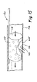
本発明の別の実施形態が、図8及び図9に示されており、図中、上述した構造的要素と類似した構造的要素は、同一符号の後に小文字“b”を付けて指示されている。かくして、図8及び図9の実施形態では、変形例としてのスリーブ60bが設けられている。細長い部材26bは、この実施形態では、近位外側管33b及び近位外側管33b内に入れ子状になった遠位外側管42bを有している。骨格構造70が、複数の曲げ可能な部材、例えばワイヤ72によって形成されており、各ワイヤは、2つの端部を有し、一方の端部は外側近位管33bに固定され、他方の端部は、遠位外側管42bに固定されている。この構成では、遠位外側管42bを近位外側管33bに対し動かして骨格構造70にロープロフィール状態とハイプロフィール状態の両方を与えることができる。
例えば、遠位外側管42bを近位外側管33bの遠位側に動かすと、ワイヤ72の端部は、間隔は広くなる。これにより、ワイヤ72は、ロープロフィール状態において細長い部材26bに密接する。しかしながら、遠位外側管42bを、近位外側管33bに対し近位側へ動かすと、ワイヤ72の端部は、間隔が密度になる。これにより、ワイヤ72は全体として半径方向に動いて図8及び図9に示すようなハイプロフィール状態になる。
Another embodiment of the present invention is shown in FIGS. 8 and 9, in which structural elements similar to the structural elements described above are indicated by the same symbol followed by a lower case “b”. Yes. Thus, in the embodiment of FIGS. 8 and 9, a sleeve 60 b as a modified example is provided. The
For example, when the distal
スリーブ60bを形成するためカバー74が、骨格構造70を覆って設けられている。このカバー74は代表的には、拡張可能な又はエラストマー材料で作られると共に少なくとも一部が骨格構造70を覆うように管状形態を備えている。カバー74は、中央部分又はくびれ部83のところにカラー又はベルト85を備え、このベルト85は、くびれ部83をハイプロフィール状態では縮径状態に維持する。その結果、カバー74とベルト85の組合せにより、スリーブ60bには砂時計の形状(鼓形)が与えられる。カバー74は、ベルト85の各側において、ワイヤ72と共に比較的大きな直径まで自由に拡張することができる。しかしながら、ベルト85は、くびれ部83の中央部分のところでは、この拡張を減少した直径に制限する。
かくして、ベルト85は、スリーブ60bに凹部67bを与え、この凹部67bはこの場合、拡張器46b,48b相互間に円周方向に形成される。スリーブ60bは、図9に示すように作動的に配置されると、体内導管部分68bを隔離し、この体内導管部分68bは、体内導管64bの丸360゜部分又は円形部分から成っている。この隔離された導管部分67bにもかかわらず、スリーブ60bは、体内導管64b内の流体の流れを続行させることができる。かくして、外科医は、導管64bの残部を通る流体の流れを妨害しないで、完全円形導管部分68bの任意の部分を外部から除去し又は穿刺することができる。
A
Thus, the
場合によっては、隔離された体内導管部分68に対して手術を施す必要は無いが、体内導管部分68を主体内導管64中の流れから隔離することが必要である。このような場合、図10に示すような実施形態が適している場合がある。図10では、上述した構造要素と類似した構造要素は、同一符号の後に小文字“c”を付けて指示されている。かくして、スリーブ60cは、この実施形態では、凹部の無い軸線方向に一様な筒体で構成されている。この場合、円筒形スリーブ60cは、例えば枝管93を含む体内導管部分91を完全に隔離する。この枝管93を主導管94c中の流れから単に隔離しようとする場合、例えば図9の実施形態において、符号67bに指示する凹部は不要である。
In some cases, it is not necessary to perform an operation on the isolated
上述の説明から、拡張器46,48は、種々の構造のものであってよいことは明らかであろう。図11〜図15の実施形態では、上述した構造要素と類似した構造要素は、同一符号の後に小文字“d”を付けて指示されている。
From the above description, it will be apparent that the
図11〜図13においては、血管除外カテーテル装置10dは、これ又拡張スリーブ113として役立つ単一の膨らまし可能な拡張器又はバルーン112を有している。この拡張スリーブ113は、ハンドル組立体20dから延びるカテーテルシャフト114に結合されている。シャフト114は、外側管116を有し、この外側管は、この場合比較的大径の貫通ルーメン118を構成している。貫通ルーメン118は、標準型のガイドワイヤを受け入れるような寸法形状のものであり、この標準型ガイドワイヤを用いると、カテーテル装置10dを配置したり、拡張スリーブ112を手術部位に差し向けることができる。
In FIGS. 11-13, the blood vessel
ハンドル組立体20dは、貫通ルーメン118への接近を制御するストップコック119を有している。膨らましポート123を介して接近できる膨らましルーメン122を備えた内側管121が、外側管116の近位部分に結合されている。好ましい実施形態では、内側管121は、貫通ルーメン118に沿って途中までしか延びておらず、拡張スリーブ112に近接して貫通ルーメン118内で終端している。かくして、膨らましルーメン122から出る膨らましガスが、貫通ルーメン118を通って拡張スリーブ112内へ差し向けられる。
このように、膨らましルーメン123からのガスは、バルーン又は拡張スリーブ112をハイプロフィール状態に膨らませる。この状態では、スリーブは、円周方向に膨らんでいるが、図13に矢印124で示す軸方向流路を構成する。
The
Thus, the gas from the
バルーン112を構成する好ましい方法が、図16,図17、図18A及び図18Bに示されている。この方法によれば、各々例えばシーム127,128,129に沿って互いに密封され又は接合された熱可塑性材料の2つの層125,126でバルーン112を形成する。また、層125,126を複数の層接合連結箇所130のところでスポット溶接するのがよい。この構成では、バルーン112は、層125,126相互間に形成され、シーム127〜129によって境界付けられる。カテーテルシャフト114をシーム127,128相互間に挿入してこれに封着するのがよい。これにより、カテーテルシャフト114、特に膨らましルーメン122を層125,126相互間でバルーン112の内部に接近させることができる。この構成では、図18Bに示すように、層125,126をそれ自体の上に巻き戻して丸め、シーム127をシーム129に取り付けることにより、バルーン112をスリーブ113の円筒形の形態に形成するのがよい。この実施形態では、凹部66dを設けることが望ましい場合、図18Aに示すように一部138を除去し、密封体139を139のところに形成して層125,126の4つの縁部を接合することにより凹部を形成できる。
A preferred method of constructing the
図18Bに示すように、カテーテルシャフト114は、多数のルーメン、即ち貫通ルーメン118及び膨らましルーメン122を備えるのがよい。この構成では、膨らましルーメン122への接近のために少なくとも1つの削ぎ部131をシャフト114に切断形成するのがよい。作用を説明すると、膨らましガスは、膨らましルーメン122から削ぎ部131を通り、層125,126相互間でバルーン112に流入することになる。
As shown in FIG. 18B, the
さらに図14及び図15を参照すると、拡張スリーブ113は、体内導管146の特定の領域144を除外し又は隔離して隔離されたチャンバ148を形成する一方で、最大流体流れを容易にすることは注目されよう。側方凹部66dは、流体投与又は治療用投与、組織生検、吻合処置のため又は体液が導管中を流れ続けている間に損傷を修復するために体内導管の一部への接近を容易にする。先の実施形態の場合と同様、装置10dを経皮的又は直接的接近により手術部位に導入することができる。
Still referring to FIGS. 14 and 15, the
図19及び図20に示す変形実施形態では、上述した構造要素と類似した構造要素は、同一符号の後に小文字“e”を付けて指示されている。かくして、この実施形態は、管組立体31e、バルーン112e、外側管116e及び膨らましルーメン122eを有している。しかしながら、この場合、追加の管151,153が、管116内に設けられている。これら追加の管151,153は、流体投与のための別のルーメン155,157をそれぞれ提供する。また、拡張スリーブ113eは、図16〜図18の実施形態に示す連結箇所130ではなく、横方向連結線159により外側バルーン層に接合された内側バルーン層を有している。
In the modified embodiment shown in FIGS. 19 and 20, structural elements similar to the structural elements described above are indicated by the same reference numeral followed by a lowercase letter “e”. Thus, this embodiment includes a
図21及び図22に示す別の実施形態では、上述した構造要素と類似した構造要素は、同一符号の後に小文字“f”を付けて指示されている。かくして、この実施形態は、管組立体31f、バルーン112f及び連結線159fを有している。しかしながら、この場合、拡張スリーブ112fを凹部67(図5)を設けずに形成することができ、かくしてこの拡張スリーブは、軸方向に一様な筒体から成ったものであってもよい。
さらに、バルーン112fの外側層126fは、その内側層125fよりも小さな厚さを備えるのがよい。層の厚さのこの差は、膨らまし時に薄い方の領域に向かうバルーン112fの拡張を容易にする。かくして、外側層127fを拡張させると内側層129fは、外側層と一緒に一様に引っ張られる。
In another embodiment shown in FIGS. 21 and 22, structural elements similar to the structural elements described above are indicated by the same reference numeral followed by a lowercase letter “f”. Thus, this embodiment has a
Further, the outer layer 126f of the
上記実施形態の具体的な開示により、本発明の精神及び範囲から逸脱することなく多くの変更例及び改造例を想到できることは明らかであろう。この理由で、図示の実施形態は、例示として記載されているに過ぎず、本発明を限定するものと解釈されてはならい。
本発明及びその種々の実施形態を説明するために本明細書において用いられている用語は、これらの一般に定義された意味において理解されるだけでなく、本明細書における特定の定義により、これら用語によって表された単一の種(species )の包括的な構造、材料又は作用を含むものである。
Obviously, many modifications and variations may be made in view of the specific disclosures of the above embodiments without departing from the spirit and scope of the invention. For this reason, the illustrated embodiments are described by way of example only and should not be construed as limiting the invention.
The terms used herein to describe the present invention and its various embodiments are not only understood in their generally defined meaning, but are also defined according to their specific definitions. Including a generic structure, material or action of a single species represented by
Claims (32)
第1の表面と、第1の表面と反対側の第2の表面とを備えた分離壁を有し、
前記壁の第1の表面は、体内導管内の体液の流れを容易にする流路を構成し、
前記壁の第2の表面は、流路及び体内導管を通る流体の流れから遮断された除外チャンバを構成していることを特徴とする流体制御装置。 A fluid control device adapted to be disposed within a body conduit to control the flow of body fluid in the body conduit,
Having a separation wall with a first surface and a second surface opposite the first surface;
The first surface of the wall constitutes a flow path that facilitates the flow of bodily fluid within the body conduit;
A fluid control device, wherein the second surface of the wall constitutes an exclusion chamber that is shielded from fluid flow through the flow path and body conduit.
細長い形態を有し、軸線に沿って近位端部と遠位端部との間に延びるシャフトと、
シャフトの遠位端部のところに設けられた拡張組立体と、
拡張組立体に含まれていて、ハイプロフィール状態とロープロフィール状態との間で動くことができる第1の拡張器と、
拡張組立体に含まれていて、全体として第1の拡張器とは別個独立にハイプロフィール状態とロープロフィール状態との間で動くことができる第2の拡張器と、
第1の拡張器及び第2の拡張器によってハイプロフィール状態とロープロフィール状態との間で運搬されるスリーブと、
を有していることを特徴とするカテーテル。 A catheter adapted to be placed in a body conduit,
A shaft having an elongated shape and extending between a proximal end and a distal end along an axis;
An expansion assembly provided at the distal end of the shaft;
A first dilator included in the expansion assembly and capable of moving between a high profile state and a low profile state;
A second dilator included in the expansion assembly and movable as a whole between the high profile state and the low profile state independently of the first dilator;
A sleeve carried between a high profile state and a low profile state by a first dilator and a second dilator;
A catheter characterized by comprising:
細長い形態を有し、軸線に沿って近位端部と遠位端部との間に延びるシャフトと、
シャフトの遠位端部のところに設けられた拡張組立体とを有し、前記拡張組立体は、体内導管内への拡張組立体の挿入を容易にするロープロフィール状態及び体内導管内での拡張組立体の動作を容易にするハイプロフィール状態を有し、
前記カテーテルは、
シャフト内に設けられた外側部材と、
シャフト内に設けられていて、外側部材と入れ子関係をなした内側部材と、
拡張組立体に含まれていて、外側部材によって支持された第1の端部及び内側部材によって支持された第2の端部を備える拡張器とを更に有し、
第1の端部と第2の端部は、拡張器がハイプロフィール状態にあるとき、全体として互いに近接した関係をなし、
第1の端部と第2の端部は、拡張器がロープロフィール状態にあるとき、全体として互いに間隔を置いた関係をなすことを特徴とするカテーテル。 A catheter adapted to be placed in a body conduit,
A shaft having an elongated shape and extending between a proximal end and a distal end along an axis;
An expansion assembly disposed at the distal end of the shaft, the expansion assembly being in a low profile state for facilitating insertion of the expansion assembly into the body conduit and expansion within the body conduit Having a high profile state that facilitates the operation of the assembly;
The catheter is
An outer member provided in the shaft;
An inner member provided in the shaft and nested with the outer member;
A dilator included in the expansion assembly and having a first end supported by the outer member and a second end supported by the inner member;
The first end and the second end are generally in close proximity to each other when the dilator is in a high profile state,
The catheter characterized in that the first end and the second end are generally spaced from each other when the dilator is in a low profile state.
細長い形態を有し、軸線に沿って近位端部と遠位端部との間に延びるシャフトと、
全体としてカテーテルシャフトの遠位端部のところに設けられた拡張組立体とを有し、
前記拡張組立体は、体内導管内への拡張組立体の挿入を容易にするロープロフィール状態及び体内導管内での拡張組立体の動作を容易にするハイプロフィール状態を有し、
前記カテーテルは、拡張組立体に含まれるバルーンを更に有し、バルーンは、これが動いてハイプロフィール状態になるよう膨らまし可能であり、
ハイプロフィール状態にあるバルーンの第1の部分は、体内導管中の流体の流れを容易にする流体流路を構成していることを特徴とするカテーテル。 A catheter adapted to be placed in a body conduit,
A shaft having an elongated configuration and extending between a proximal end and a distal end along an axis;
An expansion assembly provided generally at the distal end of the catheter shaft;
The expansion assembly has a low profile state that facilitates insertion of the expansion assembly into the body conduit and a high profile state that facilitates operation of the expansion assembly within the body conduit;
The catheter further includes a balloon included in the expansion assembly, the balloon being inflatable so that it moves to a high profile state;
A catheter wherein the first portion of the balloon in a high profile state constitutes a fluid flow path that facilitates fluid flow in the body conduit.
ハイプロフィール状態とロープロフィール状態との間で動くことができる壁を備えた拡張組立体を有するカテーテルを用意する段階と、
拡張組立体をロープロフィール状態で手術部位まで血管内へ挿入する段階と、
拡張組立体を拡張して壁をハイプロフィール状態に動かす段階とを有し、
壁はハイプロフィール状態において、血管の所定の領域と協働して血管内の血液の流れから隔離された除外キャビティを構成することを特徴とする血管内方法。 An intravascular method for restricting blood flow along a predetermined region of a blood vessel without stopping the flow of blood through the blood vessel,
Providing a catheter having an expansion assembly with a wall that is movable between a high profile state and a low profile state;
Inserting the expansion assembly into the blood vessel to the surgical site in a low profile state;
Expanding the expansion assembly to move the wall to a high profile state;
An intravascular method characterized in that, in a high profile state, the wall cooperates with a predetermined region of the blood vessel to form an exclusion cavity that is isolated from blood flow within the blood vessel.
第1のシート材料片を用意する工程と、
第2のシート材料片を少なくとも1つの周囲シームに沿って第1のシート材料片に封着して膨らましキャビティを形成する工程と、
第1のシート材料片及び第2のシート材料片をそれ自体の上に曲げ戻して膨らましキャビティに全体として円筒形の形態を与える工程と、
を有することを特徴とする方法。 A method for producing an inflatable expansion assembly comprising:
Preparing a first sheet material piece;
Sealing the second piece of sheet material along the at least one peripheral seam to the first piece of sheet material to inflate to form a cavity;
Bending the first piece of sheet material and the second piece of sheet material back onto itself to inflate to give the cavity a generally cylindrical form;
A method characterized by comprising:
Applications Claiming Priority (2)
| Application Number | Priority Date | Filing Date | Title |
|---|---|---|---|
| US33990101P | 2001-10-30 | 2001-10-30 | |
| PCT/US2002/028830 WO2003068306A1 (en) | 2001-10-30 | 2002-09-10 | Vascular exclusion catheter |
Publications (1)
| Publication Number | Publication Date |
|---|---|
| JP2006512100A true JP2006512100A (en) | 2006-04-13 |
Family
ID=27734241
Family Applications (1)
| Application Number | Title | Priority Date | Filing Date |
|---|---|---|---|
| JP2003567486A Pending JP2006512100A (en) | 2001-10-30 | 2002-09-10 | Vascular exclusion catheter |
Country Status (5)
| Country | Link |
|---|---|
| US (1) | US20050119682A1 (en) |
| EP (1) | EP1448262A4 (en) |
| JP (1) | JP2006512100A (en) |
| CA (1) | CA2465490A1 (en) |
| WO (1) | WO2003068306A1 (en) |
Cited By (1)
| Publication number | Priority date | Publication date | Assignee | Title |
|---|---|---|---|---|
| WO2012001826A1 (en) * | 2010-06-30 | 2012-01-05 | テルモ株式会社 | Medical device |
Families Citing this family (53)
| Publication number | Priority date | Publication date | Assignee | Title |
|---|---|---|---|---|
| US20090131866A1 (en) * | 2004-11-12 | 2009-05-21 | Regents Of The University Of Minnesota | Veinous Occlusion Device and Methods of Using |
| US7632285B2 (en) * | 2005-05-03 | 2009-12-15 | Ethicon Endo-Surgery, Inc. | Sheath for enabling insertion and extraction of anastomotic ring applier |
| US8052639B2 (en) * | 2007-04-10 | 2011-11-08 | Wilson David B | Clampless anastomotic device |
| US9144509B2 (en) | 2007-05-31 | 2015-09-29 | Abbott Cardiovascular Systems Inc. | Method and apparatus for delivering an agent to a kidney |
| US8216209B2 (en) | 2007-05-31 | 2012-07-10 | Abbott Cardiovascular Systems Inc. | Method and apparatus for delivering an agent to a kidney |
| US9364586B2 (en) | 2007-05-31 | 2016-06-14 | Abbott Cardiovascular Systems Inc. | Method and apparatus for improving delivery of an agent to a kidney |
| US9149610B2 (en) | 2007-05-31 | 2015-10-06 | Abbott Cardiovascular Systems Inc. | Method and apparatus for improving delivery of an agent to a kidney |
| US20090299387A1 (en) * | 2008-06-03 | 2009-12-03 | The Cleveland Clinic Foundation | Method and apparatus for fluidly isolating a portion of a body lumen wall from flow through the body lumen |
| US8323335B2 (en) | 2008-06-20 | 2012-12-04 | Edwards Lifesciences Corporation | Retaining mechanisms for prosthetic valves and methods for using |
| US20110118817A1 (en) * | 2009-11-17 | 2011-05-19 | Boston Scientific Scimed, Inc. | Stent delivery system |
| ES2922283T3 (en) | 2010-03-05 | 2022-09-12 | Edwards Lifesciences Corp | Retention mechanisms for prosthetic valves |
| US8657872B2 (en) | 2010-07-19 | 2014-02-25 | Jacques Seguin | Cardiac valve repair system and methods of use |
| US9326853B2 (en) | 2010-07-23 | 2016-05-03 | Edwards Lifesciences Corporation | Retaining mechanisms for prosthetic valves |
| US10226339B2 (en) | 2012-01-31 | 2019-03-12 | Mitral Valve Technologies Sarl | Mitral valve docking devices, systems and methods |
| US9597205B2 (en) | 2012-06-06 | 2017-03-21 | Magenta Medical Ltd. | Prosthetic renal valve |
| US10039874B2 (en) | 2013-03-13 | 2018-08-07 | Magenta Medical Ltd. | Renal pump |
| US10583231B2 (en) | 2013-03-13 | 2020-03-10 | Magenta Medical Ltd. | Blood pump |
| DE102013104948A1 (en) * | 2013-05-14 | 2014-11-20 | Acandis Gmbh & Co. Kg | Medical catheter for hypothermic treatment, treatment system with such a catheter and manufacturing method |
| GB2517283A (en) * | 2013-08-13 | 2015-02-18 | Cook Medical Technologies Llc | Double baffle vascular occluder |
| GB2517169B (en) | 2013-08-13 | 2015-07-01 | Cook Medical Technologies Llc | Double baffle vascular occluder |
| JP6328242B2 (en) | 2013-08-14 | 2018-05-23 | マイトラル・ヴァルヴ・テクノロジーズ・エス・アー・エール・エル | System for heart valve replacement |
| US10052198B2 (en) | 2013-08-14 | 2018-08-21 | Mitral Valve Technologies Sarl | Coiled anchor for supporting prosthetic heart valve, prosthetic heart valve, and deployment device |
| CN103495255B (en) * | 2013-10-12 | 2015-08-19 | 上海凯利泰医疗科技股份有限公司 | Be used for the treatment of the balloon structure of angiostenosis |
| US9622863B2 (en) | 2013-11-22 | 2017-04-18 | Edwards Lifesciences Corporation | Aortic insufficiency repair device and method |
| CR20160366A (en) | 2014-02-21 | 2016-11-15 | Mitral Valve Tecnhnologies Sarl | DEVICES, SYSTEMS AND METHODS OF SUPPLY OF PROSTHETIC MITRAL VALVE AND ANCHORAGE DEVICE |
| US10016272B2 (en) | 2014-09-12 | 2018-07-10 | Mitral Valve Technologies Sarl | Mitral repair and replacement devices and methods |
| US10231834B2 (en) | 2015-02-09 | 2019-03-19 | Edwards Lifesciences Corporation | Low profile transseptal catheter and implant system for minimally invasive valve procedure |
| WO2016185473A1 (en) | 2015-05-18 | 2016-11-24 | Magenta Medical Ltd. | Blood pump |
| US10363130B2 (en) | 2016-02-05 | 2019-07-30 | Edwards Lifesciences Corporation | Devices and systems for docking a heart valve |
| US10828150B2 (en) | 2016-07-08 | 2020-11-10 | Edwards Lifesciences Corporation | Docking station for heart valve prosthesis |
| CR20190069A (en) | 2016-08-26 | 2019-05-14 | Edwards Lifesciences Corp | Heart valve docking coils and systems |
| US10722359B2 (en) | 2016-08-26 | 2020-07-28 | Edwards Lifesciences Corporation | Heart valve docking devices and systems |
| US11039915B2 (en) | 2016-09-29 | 2021-06-22 | Magenta Medical Ltd. | Blood vessel tube |
| EP3526379B1 (en) | 2016-10-14 | 2021-08-11 | Inceptus Medical, LLC | Braiding machine and methods of use |
| CN109890431B (en) | 2016-10-25 | 2023-03-10 | 马真塔医药有限公司 | Ventricular assist device |
| US11033727B2 (en) | 2016-11-23 | 2021-06-15 | Magenta Medical Ltd. | Blood pumps |
| CN110290763B (en) | 2016-12-20 | 2022-04-05 | 爱德华兹生命科学公司 | Systems and mechanisms for deploying a docking device for replacing a heart valve |
| US11654023B2 (en) | 2017-01-23 | 2023-05-23 | Edwards Lifesciences Corporation | Covered prosthetic heart valve |
| US11013600B2 (en) | 2017-01-23 | 2021-05-25 | Edwards Lifesciences Corporation | Covered prosthetic heart valve |
| US11185406B2 (en) | 2017-01-23 | 2021-11-30 | Edwards Lifesciences Corporation | Covered prosthetic heart valve |
| USD867595S1 (en) | 2017-02-01 | 2019-11-19 | Edwards Lifesciences Corporation | Stent |
| AU2017201160B1 (en) | 2017-02-21 | 2018-04-26 | Cook Medical Technologies Llc | A medical device for temporary deployment into a bodily lumen |
| JP7296317B2 (en) * | 2017-02-24 | 2023-06-22 | インセプタス メディカル リミテッド ライアビリティ カンパニー | Vascular occlusion device and method |
| US10842619B2 (en) | 2017-05-12 | 2020-11-24 | Edwards Lifesciences Corporation | Prosthetic heart valve docking assembly |
| PL3644903T3 (en) | 2017-06-30 | 2024-03-25 | Edwards Lifesciences Corporation | Docking stations for transcatheter valves |
| AU2018291171B2 (en) | 2017-06-30 | 2023-11-30 | Edwards Lifesciences Corporation | Lock and release mechanisms for trans-catheter implantable devices |
| USD890333S1 (en) | 2017-08-21 | 2020-07-14 | Edwards Lifesciences Corporation | Heart valve docking coil |
| EP3695037B1 (en) | 2017-10-14 | 2024-03-27 | Inceptus Medical, LLC | Braiding machine and methods of use |
| US10905808B2 (en) | 2018-01-10 | 2021-02-02 | Magenta Medical Ltd. | Drive cable for use with a blood pump |
| CN115040777A (en) | 2018-01-10 | 2022-09-13 | 马真塔医药有限公司 | Ventricular assist device |
| US10893927B2 (en) | 2018-03-29 | 2021-01-19 | Magenta Medical Ltd. | Inferior vena cava blood-flow implant |
| US20210236140A1 (en) * | 2018-08-02 | 2021-08-05 | Technion Research & Development Foundation Limited | Methods and devices for blood displacement-based localized treatment |
| CN113543836B (en) | 2019-01-24 | 2024-10-11 | 马真塔医药有限公司 | Ventricular assist device |
Family Cites Families (7)
| Publication number | Priority date | Publication date | Assignee | Title |
|---|---|---|---|---|
| DE3235974A1 (en) * | 1981-11-24 | 1983-06-01 | Volkmar Dipl.-Ing. Merkel (FH), 8520 Erlangen | DEVICE FOR REMOVAL OR FOR THE EXPANSION OF CONSTRAINTS IN BODY LIQUID LEADING VESSELS |
| US5421832A (en) * | 1989-12-13 | 1995-06-06 | Lefebvre; Jean-Marie | Filter-catheter and method of manufacturing same |
| US5855565A (en) * | 1997-02-21 | 1999-01-05 | Bar-Cohen; Yaniv | Cardiovascular mechanically expanding catheter |
| US6183492B1 (en) * | 1997-08-28 | 2001-02-06 | Charles C. Hart | Perfusion-isolation catheter apparatus and method |
| DE19801076C1 (en) * | 1998-01-14 | 1999-06-24 | Voelker Wolfram Priv Doz Dr Me | Expansion catheter for by-pass surgery |
| US6626861B1 (en) * | 1998-04-22 | 2003-09-30 | Applied Medical Resources | Balloon catheter apparatus and method |
| US6231588B1 (en) * | 1998-08-04 | 2001-05-15 | Percusurge, Inc. | Low profile catheter for angioplasty and occlusion |
-
2002
- 2002-09-10 JP JP2003567486A patent/JP2006512100A/en active Pending
- 2002-09-10 WO PCT/US2002/028830 patent/WO2003068306A1/en active Application Filing
- 2002-09-10 CA CA002465490A patent/CA2465490A1/en not_active Abandoned
- 2002-09-10 EP EP02775786A patent/EP1448262A4/en not_active Withdrawn
- 2002-09-10 US US10/494,348 patent/US20050119682A1/en not_active Abandoned
Cited By (2)
| Publication number | Priority date | Publication date | Assignee | Title |
|---|---|---|---|---|
| WO2012001826A1 (en) * | 2010-06-30 | 2012-01-05 | テルモ株式会社 | Medical device |
| JP2012010880A (en) * | 2010-06-30 | 2012-01-19 | Terumo Corp | Medical device |
Also Published As
| Publication number | Publication date |
|---|---|
| US20050119682A1 (en) | 2005-06-02 |
| CA2465490A1 (en) | 2003-08-21 |
| EP1448262A4 (en) | 2008-08-06 |
| EP1448262A1 (en) | 2004-08-25 |
| WO2003068306A1 (en) | 2003-08-21 |
Similar Documents
| Publication | Publication Date | Title |
|---|---|---|
| JP2006512100A (en) | Vascular exclusion catheter | |
| US6143015A (en) | Device and method for partially occluding blood vessels using flow-through balloon | |
| US6936057B1 (en) | Device and method for partially occluding blood vessels using flow-through balloon | |
| US5320605A (en) | Multi-wire multi-balloon catheter | |
| US6350252B2 (en) | Methods and devices for occluding the ascending aorta and maintaining circulation of oxygenated blood in the patient when the patient's heart is arrested | |
| US5090958A (en) | Balloon catheters | |
| US4983167A (en) | Balloon catheters | |
| JP5178984B2 (en) | Stiffening balloon catheter for dilatation and stenting | |
| US5019042A (en) | Balloon catheters | |
| JP4205860B2 (en) | Perfusion blocking catheter device and method | |
| US5653689A (en) | Infusion catheter | |
| US5160321A (en) | Balloon catheters | |
| US6022342A (en) | Catheter introducer for antegrade and retrograde medical procedures | |
| US5147377A (en) | Balloon catheters | |
| US6039721A (en) | Method and catheter system for delivering medication with an everting balloon catheter | |
| JP2009520575A (en) | Cutting balloon catheter assembly | |
| US5290295A (en) | Insertion tool for an intraluminal graft procedure | |
| JPH0370979B2 (en) | ||
| JPH0370978B2 (en) | ||
| EP0983027B1 (en) | Device for partially occluding blood vessels | |
| JPH0313907B2 (en) | ||
| JPH06292730A (en) | Stent | |
| WO1994021321A1 (en) | Hybrid balloon angioplasty catheter and methods of use | |
| WO2008057379A1 (en) | Balloon catheter for treating hardened lesions | |
| JP2002505168A (en) | Conversion catheter incorporating a foldable lumen |
Legal Events
| Date | Code | Title | Description |
|---|---|---|---|
| A072 | Dismissal of procedure [no reply to invitation to correct request for examination] |
Free format text: JAPANESE INTERMEDIATE CODE: A072 Effective date: 20060123 |
|
| A131 | Notification of reasons for refusal |
Free format text: JAPANESE INTERMEDIATE CODE: A131 Effective date: 20081006 |
|
| A02 | Decision of refusal |
Free format text: JAPANESE INTERMEDIATE CODE: A02 Effective date: 20090309 |