JP2006511368A - Thermal printhead alignment method and apparatus - Google Patents
Thermal printhead alignment method and apparatus Download PDFInfo
- Publication number
- JP2006511368A JP2006511368A JP2004563913A JP2004563913A JP2006511368A JP 2006511368 A JP2006511368 A JP 2006511368A JP 2004563913 A JP2004563913 A JP 2004563913A JP 2004563913 A JP2004563913 A JP 2004563913A JP 2006511368 A JP2006511368 A JP 2006511368A
- Authority
- JP
- Japan
- Prior art keywords
- mounting position
- thermal printhead
- frame
- thermal
- calibration tool
- Prior art date
- Legal status (The legal status is an assumption and is not a legal conclusion. Google has not performed a legal analysis and makes no representation as to the accuracy of the status listed.)
- Pending
Links
- 238000000034 method Methods 0.000 title claims abstract description 18
- 230000007246 mechanism Effects 0.000 claims description 2
- 238000009434 installation Methods 0.000 claims 1
- 239000004065 semiconductor Substances 0.000 description 5
- 238000004519 manufacturing process Methods 0.000 description 4
- 230000000712 assembly Effects 0.000 description 3
- 238000000429 assembly Methods 0.000 description 3
- 230000008901 benefit Effects 0.000 description 3
- 239000002131 composite material Substances 0.000 description 2
- 238000012986 modification Methods 0.000 description 2
- 230000004048 modification Effects 0.000 description 2
- 230000007547 defect Effects 0.000 description 1
- 238000010438 heat treatment Methods 0.000 description 1
- 230000008569 process Effects 0.000 description 1
- 230000008439 repair process Effects 0.000 description 1
Images
Classifications
-
- B—PERFORMING OPERATIONS; TRANSPORTING
- B41—PRINTING; LINING MACHINES; TYPEWRITERS; STAMPS
- B41J—TYPEWRITERS; SELECTIVE PRINTING MECHANISMS, i.e. MECHANISMS PRINTING OTHERWISE THAN FROM A FORME; CORRECTION OF TYPOGRAPHICAL ERRORS
- B41J2/00—Typewriters or selective printing mechanisms characterised by the printing or marking process for which they are designed
- B41J2/315—Typewriters or selective printing mechanisms characterised by the printing or marking process for which they are designed characterised by selective application of heat to a heat sensitive printing or impression-transfer material
- B41J2/32—Typewriters or selective printing mechanisms characterised by the printing or marking process for which they are designed characterised by selective application of heat to a heat sensitive printing or impression-transfer material using thermal heads
- B41J2/335—Structure of thermal heads
- B41J2/33575—Processes for assembling process heads
-
- B—PERFORMING OPERATIONS; TRANSPORTING
- B41—PRINTING; LINING MACHINES; TYPEWRITERS; STAMPS
- B41J—TYPEWRITERS; SELECTIVE PRINTING MECHANISMS, i.e. MECHANISMS PRINTING OTHERWISE THAN FROM A FORME; CORRECTION OF TYPOGRAPHICAL ERRORS
- B41J2/00—Typewriters or selective printing mechanisms characterised by the printing or marking process for which they are designed
- B41J2/315—Typewriters or selective printing mechanisms characterised by the printing or marking process for which they are designed characterised by selective application of heat to a heat sensitive printing or impression-transfer material
- B41J2/32—Typewriters or selective printing mechanisms characterised by the printing or marking process for which they are designed characterised by selective application of heat to a heat sensitive printing or impression-transfer material using thermal heads
- B41J2/335—Structure of thermal heads
- B41J2/3359—Manufacturing processes
Landscapes
- Engineering & Computer Science (AREA)
- Manufacturing & Machinery (AREA)
- Electronic Switches (AREA)
- Common Mechanisms (AREA)
Abstract
熱プリントヘッド(14)を取り付けるためのデバイスを記載する。このデバイスは、基準部材(24)および熱プリントヘッドを取り付ける位置(17)周辺に直交に配向された多数の調節可能な基準点(11、20)を含むフレーム(12)を備える。この基準点は、基準部材に対して取り付け位置に熱プリントヘッドを正確に位置決めするための調整のために適合される。また別の局面において、本発明は、プリントヘッドアセンブリに一以上の熱プリントヘッドを整列するための方法に関する。A device for mounting a thermal printhead (14) is described. The device comprises a frame (12) comprising a number of adjustable reference points (11, 20) oriented orthogonally around a reference member (24) and a location (17) for mounting a thermal printhead. This reference point is adapted for adjustment to accurately position the thermal print head in the mounting position relative to the reference member. In yet another aspect, the invention relates to a method for aligning one or more thermal printheads with a printhead assembly.
Description
(関連出願の参照)
本出願は、仮出願第60/436,353号(2002年12月23日出願)の利益を主張する。
(Refer to related applications)
This application claims the benefit of provisional application 60 / 436,353 (filed December 23, 2002).
(技術分野)
本発明は、熱プリントヘッドアセンブリに関し、特にこれらアセンブリにおける熱プリントヘッドの整列に関する。
(Technical field)
The present invention relates to thermal printhead assemblies, and more particularly to alignment of thermal printheads in these assemblies.
(発明の背景)
現代の熱プリントヘッドは、互いに近接した多数の個々の加熱エレメントの位置決めをし得る集積回路構築物に基づく解像度レベルを得た。この解像度のアドバンテージは、製造過程および後のプリント用途の両方において、半導体に生じる欠陥の可能性のためにプリントヘッドの全間隔の制限を生じる。より長いプリント間隔は、より広い間隔を得るために二以上のより小さいプリントヘッドを整列することにより達成された。また、得られた解像度により、このような複数のプリントヘッドの間の比較的小さな誤整列は、生じたプリント産物において容易に認められる。1ピクセルほどの小さな誤整列でさえ、視覚的に決定され得る。
(Background of the Invention)
Modern thermal printheads have achieved resolution levels based on integrated circuit structures that can position a large number of individual heating elements in close proximity to each other. This resolution advantage creates a limitation on the overall spacing of the printhead due to potential defects in the semiconductor, both in the manufacturing process and in later printing applications. Longer print spacing was achieved by aligning two or more smaller printheads to obtain wider spacing. Also, due to the resolution obtained, such a relatively small misalignment between multiple print heads is easily recognized in the resulting print product. Even misalignments as small as one pixel can be determined visually.
(発明の要旨)
本発明の一つの局面は、熱プリントヘッドを取り付けるためのデバイスに関し、このデバイスは、基準部材を含むフレーム;および熱プリントヘッドの取り付け位置周辺に直交に配向された多数の調整可能な基準点を備え、この基準点は、基準部材に対して取り付け位置に熱プリントヘッドを正確に位置させるための調整のために適合させられる。
(Summary of the Invention)
One aspect of the invention relates to a device for mounting a thermal printhead, the device comprising a frame including a reference member; and a number of adjustable reference points oriented orthogonally around the mounting position of the thermal printhead. And the reference point is adapted for adjustment to accurately position the thermal printhead in the mounting position relative to the reference member.
このデバイスは、多数の調整可能な基準点に対して取り付け位置において熱プリントヘッドを付勢するために構成された一以上の付勢機構を備え得る。このデバイスは、多数の調整可能な基準点に対して付勢されながら、取り付け位置にプリントヘッドの位置を固定するための固定可能なデバイスをさらに備える。 The device may include one or more biasing mechanisms configured to bias the thermal print head in the mounting position relative to a number of adjustable reference points. The device further comprises a fixable device for fixing the position of the print head in the mounting position while being biased against a number of adjustable reference points.
このデバイスは、取り付け位置への配置のための熱プリントヘッド様の形状をした第一の部分およびこの第一の部分から伸長する強固な位置決め部材を有するキャリブレーションツールをさらに備え得る。この位置決め部材は、基準点が、取り付け位置に後に設置されるべき熱プリントヘッドの位置を決定するために調整されている間、取り付け位置に第一の部分を正確に位置決めするためにフレームの基準部材に接するように構成される。この基準部材は、実質的な平らな面およびこの実質的な平らな面に平行に取り付けられた円柱状のエレメントを備え得る。 The device may further comprise a calibration tool having a first portion shaped like a thermal printhead for placement in the mounting position and a rigid positioning member extending from the first portion. This positioning member is used as a reference for the frame to accurately position the first part at the mounting position while the reference point is adjusted to determine the position of the thermal printhead to be subsequently installed at the mounting position. It is comprised so that a member may be contact | connected. The reference member may comprise a substantially flat surface and a cylindrical element mounted parallel to the substantially flat surface.
別の局面において、本発明は、プリントヘッドアセンブリに一以上の熱プリントヘッドを整列するための方法に関し、この方法は、基準部材を有するフレームおよび熱プリントヘッドの取り付け位置周辺に直交に配向された多数の調整可能な基準点を提供する工程、取り付け位置に配置するための熱プリントヘッド様の形状をした第一の部分およびこの第一の部分から伸長する強固な位置決め部材を有するキャリブレーションツールを提供する工程、取り付け部分に第一の部分と共にキャリブレーションツールを位置決める工程および取り付け位置に第一の部分を正確に位置決めるためにフレームの基準部材に接する位置決め部材を位置決める工程、ならびに取り付け位置に後に設置されるべき熱プリントヘッドの正確な位置を決定するために基準点を調整する工程、を包含する。 In another aspect, the present invention relates to a method for aligning one or more thermal printheads with a printhead assembly, the method oriented orthogonally around a frame having a reference member and a thermal printhead mounting location. A calibration tool having a process for providing a large number of adjustable reference points, a first part shaped like a thermal printhead for placement in an attachment position, and a rigid positioning member extending from the first part Providing, positioning the calibration tool together with the first part at the mounting part, positioning a positioning member in contact with the frame reference member to accurately position the first part at the mounting position, and mounting position To determine the exact position of the thermal print head to be installed later Step of adjusting the reference points including,.
この方法は、調整する工程の間にキャリブレーションツールをフレームに取り付ける工程をさらに包含し得る。この方法は、さらに調整された基準点に対し取り付け位置の熱プリントヘッドを調整および設置する工程の後にこのキャリブレーションをフレームから除去する工程を包含する。さらにこの方法は、基準点に対して取り付け位置に設置されたプリンタヘッドを機械的に付勢する工程をさらに包含する。この方法は、基準点に対して取り付け位置にプリンタヘッドを固定する工程もまた包含し得る。 The method may further include attaching a calibration tool to the frame during the adjusting step. The method further includes removing the calibration from the frame after adjusting and installing the thermal printhead in the mounting position relative to the adjusted reference point. The method further includes mechanically urging the printer head installed at the mounting position with respect to the reference point. The method may also include the step of fixing the printer head in the mounting position relative to the reference point.
これらの変更物は、複合的なプリントヘッドアセンブリに重要である、改善された熱プリントヘッドの整列を提供する。これは、アセンブリの高精度の組み立てを必要とすることなく達せられる。 These modifications provide improved thermal printhead alignment, which is important for composite printhead assemblies. This is achieved without the need for high precision assembly of the assembly.
(好ましい実施形態の説明)
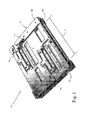
熱プリントヘッドアセンブリ10は、図1に示され、一般に、取り付けフレーム12および4つの設置されたプリントヘッド13、14、15、16を備える。この開示の範囲のために、熱プリントヘッドについての全ての参照は、半導体部分(プリントヘッド13、15に示される)および半導体のホルダー部分(プリントヘッド14、16に示される)を必ず備える。フレーム12は、二つのセクション12a、12bから構成され、フレームセクション12a上に取り付けられたプリントヘッド14、16を有する。フレームセクション12bは、反対のフレームセクション12bに設計され、プリント媒体経路11を通過するプリント媒体の反対側にプリントするためのさらなる対のプリントヘッド13、15を取り付ける。
(Description of Preferred Embodiment)
A
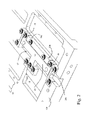
図2は、熱プリントヘッド14のクローズアップ図を示す。この熱プリントヘッド14は、取り付け位置17に取り付けられ、多数のねじ18により所定の位置に保持される。取り付け位置17内の熱プリントヘッド14の位置は、多数のセットねじ20a、20bおよび20cにより正確に決定される。セットねじ20aおよび20bは、熱プリントヘッド14の一つの細長い側面に沿って位置付けされ、セットねじ20cは、この細長い側面に対して直交する側面に沿って位置させられる。この直交する配置の使用により、熱プリントヘッド14の位置は、正確に決定され得る。
FIG. 2 shows a close-up view of the
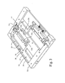
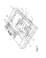
図3は、反対の角度からみた、プリントヘッド14の無い同一のフレームセクション12a(図1)を示す。取り付け位置17にプリントヘッド14が無いために、セットねじ20a、20b、20cによりそれぞれ形成される多数の基準点21a、21b、21cがあらわにされる。対のバネ装填型プランジャー22a、22bがまた示される。バネ装填型プランジャー22a、22bは、取り付け位置16へ伸長しそして、二つの直交する方向に基準点21a、21bおよび21cに対して熱プリントヘッドを付勢させることに役立つ。プリントヘッド13〜16各々についての各取り付け位置は、セットねじ、基準点およびバネ装填型プランジャーと同一のセットを備える。
FIG. 3 shows the
図3は、実質的に平らの基準面25およびこの基準面25に平行に取り付けられた円柱状の基準部材26を有する基準部材24をさらに示す。多数のねじ山付きのねじ穴28もまた示される。
FIG. 3 further shows a
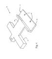
図4は、キャリブレーションツール30を示し、アセンブリ10に熱プリントヘッド14を設置する前に、調整可能な基準点21a、21b、21c(図3)の各々を整列するために熱プリントヘッドアセンブリ10(図1)と共に使用するように構成される。キャリブレーションツール30は、少なくとも熱プリントヘッド部分様の形状にされた第一の部分32および位置決め部材34を備える。位置決め部材34は、基準面36,37および対のねじ穴38を備える。
FIG. 4 shows the
図5は、熱プリントヘッド14の変わりに取り付け位置17に配置された第一の部分32を有するフレーム12に配置されたキャリブレーションツール30を示す。第一の部分32は、基準面25(図2)に接する基準面36(図4)および円柱状基準部材26に接する基準面37(図4)により整列する。この位置において、キャリブレーションツール30は、ねじ穴38およびねじ山付きのねじ穴28(図2)を使用してねじ(図示せず)により固定される。この様式において、第一の部分32は、基準部材24に対して正確に整列される。この位置におけるキャリブレーションツール30と共に、セットねじ20a、20bおよび20cは、調整され、その結果、基準点21a、21b、21c(図3)は、第一の部分32に接し、従ってキャリブレーションツール30により決定された整列位置を設定する。
FIG. 5 shows a
一旦セットねじ20a、20b、20cが、正確に調整されると、キャリブレーションツール30は、取り除かれ、そして熱プリントヘッド14(図1)は、取り付け位置17に配置される。この位置において、バネ装填型プランジャー22a、22bは、熱プリントヘッド14をセットねじ20a、20b、20cにより決定される基準点21a、21b、21cに対して物理的に付勢する。この様式において正確に整列された熱プリントヘッド14と共に、ねじ18(図1)は、熱プリントヘッド14の位置を固定するために設置される。
Once the
図5は、どのように複合プリントヘッドが、同一の基準面24に対して単一フレーム12内にキャリブレートされるのかについてさらに示す。別のキャリブレーションツール42が、プリントヘッド15の取り付け位置44の基準を提供することを示す。キャリブレーションツール42は、同様の基準面25および円柱状基準面26に対して基準とされる。この様式において、プリントヘッド取り付け位置17、44は、同様の基準部材に対してキャリブレートされる。このフレームの精密な製造は、重要ではなくなる。
FIG. 5 further illustrates how a composite printhead is calibrated within a
プリントヘッド15(図1)が、フレームセクション12bに取り付けられることに注意すべきである。従って、全ての4つのプリントヘッド13〜16は、二面プリントのために、単一のプリントアセンブリ10に取り付けられ、フレーム12の高精度の製造を必要とすることなく、全く同じ基準面25および円柱状基準部材26を使用して容易かつ非常に正確に整列され得る。
Note that the printhead 15 (FIG. 1) is attached to the frame section 12b. Thus, all four printheads 13-16 are attached to a
本方法および装置は、熱プリントヘッド14のための高度に再現可能である整列を提供する。この整列は、およそ10〜15ミクロン、または代表的なピクセル幅未満である。このアプローチは、高精度に機械加工されたフレーム12の必要なく、適切な整列をさらに可能にする。その代わりに、高度の正確性が、キャリブレーションツール30、42に単純に機械加工され、キャリブレーションツールは、熱プリンタの製造者により保持されかつ制御される。熱プリンタ整列に対するこのアプローチは、非常に確実でありかつ再現可能であることが証明されており、基準点の再設定を行う必要なく多くのプリントヘッドの取り付けおよび取り外しを可能にする。たとえ再設定が必要な場合であっても、修理責任者が容易にキャリブレーションツール30を輸送し得、非常にわずかの時間で基準点を直ちに再調整し得る。このアプローチは、たとえプリントヘッドの半導体部分が、その製造において交換された場合であっても、キャリブレーションが普遍のままであるというアドバンテージをさらに有する。このプリントヘッドの製造元は、ホルダー部分内の半導体部分の整列をただ制御することのみを必要とする。
The method and apparatus provide a highly reproducible alignment for the
本発明は、種々の好ましい実施形態に関して詳細に記載されるが、これらに限定されることを意図せず、むしろ当業者は、本発明の意図および添付の特許請求の範囲内で変更および改変が可能であることを認識する。 The present invention will be described in detail with reference to various preferred embodiments, but is not intended to be limited thereto, rather, those skilled in the art may make changes and modifications within the spirit of the invention and the appended claims. Recognize that it is possible.
本発明および他の目的ならびにそれらのさらなる特徴をより理解するために、以下の添付の図面と共に種々の好ましい実施形態の詳細な説明が参照される。
Claims (12)
基準部材を備えるフレーム;および
熱プリントヘッドの取り付け位置周囲に直交するように配向された多数の調整可能な基準点であって、該基準点は、該基準部材に対して該取り付け位置に熱プリントヘッドを正確に位置決めするための調整のために適合される、基準点、
を備える、デバイス。 A device for mounting a thermal printhead, the device comprising:
A frame comprising a reference member; and a number of adjustable reference points oriented orthogonally around a mounting position of the thermal printhead, the reference point being in the mounting position relative to the reference member Reference point, adapted for adjustment to accurately position the head,
A device comprising:
をさらに備える、デバイス。 2. A calibration tool according to claim 1, comprising a first part shaped like a thermal printhead for placement at the mounting position and a rigid positioning member extending from the first part. The positioning member accurately positions the first portion at the mounting position while the reference point is adjusted to determine the position of the thermal printhead for later installation at the mounting position. A calibration tool adapted to contact the reference member of the frame to
The device further comprising:
基準部材を備えるフレーム、および熱プリントヘッドの取り付け位置周囲に直交するように配向された多数の調整可能な基準点を提供する工程;
該取り付け位置に配置するための熱プリントヘッド様形状の第一部分および該第一部分から伸張する強固な位置決め部材を有するキャリブレーションツールを提供する工程;
該取り付け位置に該第一部分を有する該キャリブレーションツールを位置付け、および該取り付け位置に該第一部分を正確に位置させるために該フレームの該基準部材と接する該位置決め部材を位置付ける工程;ならびに
該取り付け位置に後に設置されるべき熱プリントヘッドの正確な位置を決定するために該基準点を調節する工程、
を包含する、方法。 A method for aligning one or more thermal printheads with a printhead assembly, the method comprising the following steps:
Providing a frame with a reference member and a number of adjustable reference points oriented orthogonally around the mounting position of the thermal printhead;
Providing a calibration tool having a thermal printhead-like shaped first portion for placement at the attachment location and a rigid positioning member extending from the first portion;
Positioning the calibration tool having the first portion at the mounting position and positioning the positioning member in contact with the reference member of the frame to accurately position the first portion at the mounting position; and the mounting position Adjusting the reference point to determine the exact position of the thermal printhead to be subsequently installed;
Including the method.
Applications Claiming Priority (2)
| Application Number | Priority Date | Filing Date | Title |
|---|---|---|---|
| US43635302P | 2002-12-23 | 2002-12-23 | |
| PCT/US2003/040867 WO2004058505A2 (en) | 2002-12-23 | 2003-12-22 | Thermal print head alignment method and apparatus |
Publications (1)
| Publication Number | Publication Date |
|---|---|
| JP2006511368A true JP2006511368A (en) | 2006-04-06 |
Family
ID=32682382
Family Applications (1)
| Application Number | Title | Priority Date | Filing Date |
|---|---|---|---|
| JP2004563913A Pending JP2006511368A (en) | 2002-12-23 | 2003-12-22 | Thermal printhead alignment method and apparatus |
Country Status (6)
| Country | Link |
|---|---|
| US (1) | US6940533B2 (en) |
| EP (1) | EP1587686A2 (en) |
| JP (1) | JP2006511368A (en) |
| AU (1) | AU2003297454A1 (en) |
| CA (1) | CA2511537C (en) |
| WO (1) | WO2004058505A2 (en) |
Families Citing this family (3)
| Publication number | Priority date | Publication date | Assignee | Title |
|---|---|---|---|---|
| WO2013070727A1 (en) | 2011-11-07 | 2013-05-16 | Zih Corp. | Media processing device with enhanced media and ribbon loading and unloading features |
| US9744784B1 (en) | 2016-02-05 | 2017-08-29 | Zih Corp. | Printhead carriers and adapters |
| CN114701262B (en) * | 2022-03-03 | 2024-02-27 | 芯体素(杭州)科技发展有限公司 | Multi-independent nozzle printing equipment for non-flat substrate surface and printing method thereof |
Family Cites Families (3)
| Publication number | Priority date | Publication date | Assignee | Title |
|---|---|---|---|---|
| US5038155A (en) | 1988-07-22 | 1991-08-06 | Fuji Photo Film Co., Ltd. | Recording apparatus |
| JPH03138161A (en) * | 1989-10-25 | 1991-06-12 | Mutoh Ind Ltd | Thermal recorder |
| US6298783B1 (en) * | 1999-10-29 | 2001-10-09 | Fargo Electronics, Inc. | Printhead alignment device and method of use |
-
2003
- 2003-12-22 JP JP2004563913A patent/JP2006511368A/en active Pending
- 2003-12-22 WO PCT/US2003/040867 patent/WO2004058505A2/en not_active Ceased
- 2003-12-22 EP EP03814286A patent/EP1587686A2/en not_active Withdrawn
- 2003-12-22 CA CA002511537A patent/CA2511537C/en not_active Expired - Fee Related
- 2003-12-22 US US10/743,234 patent/US6940533B2/en not_active Expired - Fee Related
- 2003-12-22 AU AU2003297454A patent/AU2003297454A1/en not_active Abandoned
Also Published As
| Publication number | Publication date |
|---|---|
| AU2003297454A1 (en) | 2004-07-22 |
| WO2004058505A3 (en) | 2005-01-13 |
| US6940533B2 (en) | 2005-09-06 |
| WO2004058505A2 (en) | 2004-07-15 |
| EP1587686A2 (en) | 2005-10-26 |
| US20040141044A1 (en) | 2004-07-22 |
| CA2511537C (en) | 2009-03-24 |
| AU2003297454A8 (en) | 2004-07-22 |
| CA2511537A1 (en) | 2004-07-15 |
Similar Documents
| Publication | Publication Date | Title |
|---|---|---|
| JP6524173B2 (en) | Fluid discharge module mounted | |
| US5475409A (en) | Alignment structure for components of an ink jet print head | |
| KR20090007227A (en) | Self-aligned precision reference point for array die placement | |
| JP2007535433A (en) | Positioning the droplet ejection device | |
| JP4874269B2 (en) | Printer mounting member and manufacturing method | |
| JP2006511368A (en) | Thermal printhead alignment method and apparatus | |
| TWI682196B (en) | Apparatus and method of mounting a tall rochon polarizer | |
| JP2016517972A5 (en) | ||
| US6511574B2 (en) | Fixture for securing hard stops to a substrate | |
| US20240095940A1 (en) | Liquid ejection head and liquid ejection apparatus including the same | |
| JP2010251843A (en) | Method of manufacturing imaging device, and imaging device | |
| US11179933B2 (en) | Printhead die assembly | |
| JP2007127808A (en) | Exposure apparatus | |
| US20010045020A1 (en) | Method and apparatus for securing and aligning bubble vials | |
| US20250362472A1 (en) | Fine adjustment system for optics components | |
| GB2460854A (en) | Printhead mounting plate | |
| JPH09197236A (en) | Lens height adjusting device | |
| TWI619948B (en) | Probe module, probe head and manufacturing method thereof | |
| CN119124565A (en) | Lens module test fixture | |
| JP3132533B2 (en) | Printhead positioning mechanism and printhead positioning method | |
| JP4507346B2 (en) | Optical writing head and method of assembling the same | |
| JPH05183677A (en) | Assembly method for picture device | |
| JP2003001860A (en) | Thermal recorder | |
| JPH0615850A (en) | Thermal head | |
| JP2004070287A (en) | Apparatus for manufacturing printing form |
Legal Events
| Date | Code | Title | Description |
|---|---|---|---|
| A711 | Notification of change in applicant |
Free format text: JAPANESE INTERMEDIATE CODE: A711 Effective date: 20070607 |
|
| A977 | Report on retrieval |
Free format text: JAPANESE INTERMEDIATE CODE: A971007 Effective date: 20080423 |
|
| A131 | Notification of reasons for refusal |
Free format text: JAPANESE INTERMEDIATE CODE: A131 Effective date: 20080425 |
|
| A02 | Decision of refusal |
Free format text: JAPANESE INTERMEDIATE CODE: A02 Effective date: 20080929 |