JP2006509925A - Web zone stretching - Google Patents
Web zone stretching Download PDFInfo
- Publication number
- JP2006509925A JP2006509925A JP2004560299A JP2004560299A JP2006509925A JP 2006509925 A JP2006509925 A JP 2006509925A JP 2004560299 A JP2004560299 A JP 2004560299A JP 2004560299 A JP2004560299 A JP 2004560299A JP 2006509925 A JP2006509925 A JP 2006509925A
- Authority
- JP
- Japan
- Prior art keywords
- web
- zone
- stretching
- width
- zones
- Prior art date
- Legal status (The legal status is an assumption and is not a legal conclusion. Google has not performed a legal analysis and makes no representation as to the accuracy of the status listed.)
- Pending
Links
Images


Classifications
-
- B—PERFORMING OPERATIONS; TRANSPORTING
- B29—WORKING OF PLASTICS; WORKING OF SUBSTANCES IN A PLASTIC STATE IN GENERAL
- B29C—SHAPING OR JOINING OF PLASTICS; SHAPING OF MATERIAL IN A PLASTIC STATE, NOT OTHERWISE PROVIDED FOR; AFTER-TREATMENT OF THE SHAPED PRODUCTS, e.g. REPAIRING
- B29C55/00—Shaping by stretching, e.g. drawing through a die; Apparatus therefor
- B29C55/02—Shaping by stretching, e.g. drawing through a die; Apparatus therefor of plates or sheets
- B29C55/04—Shaping by stretching, e.g. drawing through a die; Apparatus therefor of plates or sheets uniaxial, e.g. oblique
- B29C55/08—Shaping by stretching, e.g. drawing through a die; Apparatus therefor of plates or sheets uniaxial, e.g. oblique transverse to the direction of feed
-
- B—PERFORMING OPERATIONS; TRANSPORTING
- B29—WORKING OF PLASTICS; WORKING OF SUBSTANCES IN A PLASTIC STATE IN GENERAL
- B29C—SHAPING OR JOINING OF PLASTICS; SHAPING OF MATERIAL IN A PLASTIC STATE, NOT OTHERWISE PROVIDED FOR; AFTER-TREATMENT OF THE SHAPED PRODUCTS, e.g. REPAIRING
- B29C55/00—Shaping by stretching, e.g. drawing through a die; Apparatus therefor
-
- Y—GENERAL TAGGING OF NEW TECHNOLOGICAL DEVELOPMENTS; GENERAL TAGGING OF CROSS-SECTIONAL TECHNOLOGIES SPANNING OVER SEVERAL SECTIONS OF THE IPC; TECHNICAL SUBJECTS COVERED BY FORMER USPC CROSS-REFERENCE ART COLLECTIONS [XRACs] AND DIGESTS
- Y10—TECHNICAL SUBJECTS COVERED BY FORMER USPC
- Y10T—TECHNICAL SUBJECTS COVERED BY FORMER US CLASSIFICATION
- Y10T428/00—Stock material or miscellaneous articles
- Y10T428/24—Structurally defined web or sheet [e.g., overall dimension, etc.]
- Y10T428/24942—Structurally defined web or sheet [e.g., overall dimension, etc.] including components having same physical characteristic in differing degree
Abstract
ウェブ(40)の1つまたは複数のゾーン(I〜V)を延伸するための装置および方法が開示される。延伸されたまたは活性化されたゾーンを含むウェブもまた開示される。ウェブ中のゾーンのそれぞれは、クロス−ウェブ方向(8)、すなわち、ダウン−ウェブ方向(8)に対して直角の方向(8)に延伸される。その延伸は、ウェブがダウン−ウェブ方向に装置を通って前進中である時に連続的に行うことができる。延伸は、ウェブの延伸されるゾーンとの物理的接触の不存在下に起こり得る。延伸されたゾーンに誘発される歪みは、延伸距離にわたって徐々に導入され得る。歪みは一次速度で増加することができる。本延伸法および装置は、ウェブ内の弾性ゾーンを活性化するために用いられてもよい。An apparatus and method for stretching one or more zones (IV) of the web (40) is disclosed. Webs that include stretched or activated zones are also disclosed. Each of the zones in the web is stretched in the cross-web direction (8), that is, in a direction (8) perpendicular to the down-web direction (8). The stretching can occur continuously as the web is being advanced through the device in the down-web direction. Stretching can occur in the absence of physical contact with the stretched zone of the web. The strain induced in the stretched zone can be introduced gradually over the stretch distance. Distortion can increase at the primary rate. The stretching method and apparatus may be used to activate an elastic zone in the web.
Description
本発明は、ウェブ、ウェブ加工方法、およびウェブ加工装置の分野に関する。より具体的には、本発明は、ウェブの1つまたは複数のゾーンをクロス−ウェブ方向に延伸するための装置および方法ならびにそのように延伸されたウェブを提供する。 The present invention relates to the field of webs, web processing methods, and web processing devices. More specifically, the present invention provides an apparatus and method for stretching one or more zones of a web in the cross-web direction and a web so stretched.
ウェブを加工中にクロス−ウェブ方向に延伸することは多くの場合に望ましいかもしれない。例えば、非弾性材料の層を含むウェブ、例えば、弾性層に積層されたまたは別のやり方でそれに貼り付けられた不織ウェブは、典型的には、ウェブに弾性を与えるために延伸を必要とする。非弾性層または非弾性層内の結合が破壊されるまたは別のやり方で分断されるようにウェブを延伸すると、ウェブ内に置かれた弾性材料の1つまたは複数の層のために延伸された弾性ウェブを残す。ウェブに弾性を与えるためのかかる延伸は、(ウェブの弾性が延伸によって「活性化」されて)ウェブの「活性化」と一般に言われる。活性化は、例えば、幅出しおよびリングローリングをはじめとする様々な方法によって行うことができる。 It may be desirable in many cases to stretch the web in the cross-web direction during processing. For example, a web comprising a layer of non-elastic material, such as a nonwoven web laminated to or otherwise affixed to the elastic layer, typically requires stretching to impart elasticity to the web. To do. When the web is stretched such that the inelastic layer or bond within the inelastic layer is broken or otherwise broken, it is stretched for one or more layers of elastic material placed within the web Leave an elastic web. Such stretching to impart elasticity to the web is commonly referred to as “activation” of the web (when the elasticity of the web is “activated” by stretching). Activation can be performed by various methods including, for example, tentering and ring rolling.
幅出しは典型的にはウェブの縁をつかみ、ウェブをダウン−ウェブ方向に(すなわち、ウェブの長さに沿って)前進させながらウェブをクロス−ウェブ方向に延伸することを含む。幅出しはウェブ中に誘発される歪みの量を変える能力を提供するけれども、それはまた多数の不利を被る。例えば、ウェブの縁は、縁でのウェブにおける損傷または一貫性のない歪みのために、幅出し後にしばしば廃棄されなければならない。別の潜在的な不利は、幅出しを用いてウェブの選択された部分またはゾーン中へ歪みを誘発することが困難であるまたは不可能であることである。さらに、幅出し装置は、コストがかかり、複雑でもあり得るし、運転するためにかなりの量の床面積を必要とするかもしれない。 Tentering typically involves gripping the edges of the web and stretching the web in the cross-web direction while advancing the web in the down-web direction (ie, along the length of the web). Although tentering provides the ability to change the amount of strain induced in the web, it also suffers from a number of disadvantages. For example, web edges often have to be discarded after tentering due to damage or inconsistent distortion in the web at the edges. Another potential disadvantage is that it is difficult or impossible to induce strain into selected portions or zones of the web using tentering. Furthermore, tentering devices can be costly and complex and may require a significant amount of floor space to operate.
リングローリングは、ウェブを延伸するための幅出しに代わる代替案を提供する。様々なリングローリング装置が、例えば、米国特許第5,143,679号明細書(ウェーバー(Weber)ら)、同第5,156,793号明細書(ブエル(Buell)ら)、および同第5,167,897号明細書(ウェーバーら)に記載されている。リングローリングはウェブ中の選択されたゾーンを延伸するために用いることができるが、リングローリングの不利には、例えば、ウェブの外観に望ましくない影響を及ぼすかもしれないリングローリング装置によるウェブの接触が含まれるかもしれない。リングローリングを用いてウェブ中に誘発され得る歪みの量はリングローリング装置によって制限されるかもしれない。歪み量の調節または変化は困難であるまたは制限されるかもしれない。さらに、リングローリング装置は歪みの量の変化を達成するために典型的には停止されなければならない。加えて、リングローリングは典型的にはウェブへの非一次歪みの迅速な適用を含み、その結果ウェブは裂けまたは破れ、それによって過度の廃棄物をもたらすかもしれない。 Ring rolling provides an alternative to tentering to stretch the web. Various ring rolling devices are described, for example, in US Pat. Nos. 5,143,679 (Weber et al.), 5,156,793 (Buell et al.), And 167, 897 (Weber et al.). While ring rolling can be used to stretch selected zones in the web, disadvantages of ring rolling include, for example, contact of the web with a ring rolling device that may undesirably affect the appearance of the web. May be included. The amount of strain that can be induced in a web using ring rolling may be limited by the ring rolling device. Adjusting or changing the amount of distortion may be difficult or limited. Furthermore, ring rolling devices typically must be stopped to achieve a change in the amount of distortion. In addition, ring rolling typically involves the rapid application of non-first order strain to the web, so that the web may tear or tear, thereby causing excessive waste.
本発明は、ウェブの1つまたは複数のゾーンを延伸するための装置および方法ならびに1つまたは複数の延伸されるゾーンを含むウェブを提供する。ウェブ中の延伸されるゾーンのそれぞれはクロス−ウェブ方向、すなわち、ダウン−ウェブ方向に対して横断方向に延伸される。延伸は、ウェブがダウン−ウェブ方向に装置を通って前進中である間に連続的に行うことができる。 The present invention provides an apparatus and method for stretching one or more zones of a web and a web comprising one or more stretched zones. Each of the stretched zones in the web is stretched in the cross-web direction, i.e., transverse to the down-web direction. Stretching can occur continuously while the web is being advanced through the device in the down-web direction.
ウェブの延伸されるゾーンとの物理的接触の不存在下に延伸が起こり得ることは本発明の方法および装置の潜在的な利点の一つである。物理的接触の当該欠如は延伸中にウェブのマーキングを防ぐかもしれない。さらに、延伸中のウェブの延伸される部分との接触は、例えば、ウェブが延伸中に特に脆い場合、ウェブの破壊または引裂をもたらすかもしれない。 It is one of the potential advantages of the method and apparatus of the present invention that stretching can occur in the absence of physical contact with the zone of the web being stretched. This lack of physical contact may prevent web marking during stretching. Further, contact with the stretched portion of the web during stretching may lead to web breakage or tearing, for example if the web is particularly brittle during stretching.
本発明の装置および方法の別の潜在的な利点は、ウェブの引裂または破壊をもたらし得る迅速な延伸を回避できるように、延伸されるゾーン上に誘発される歪みを延伸距離にわたって徐々に導入できることである。一アプローチでは、本発明の方法および装置は、例えば、リングローリングでの歪みの非一次誘発とは対照的に一次速度で増加する歪みを提供することができる。歪みの一次性は、歪みの突然の適用によるウェブの破壊または引裂の潜在的な問題を減らすのに役立つであろう。 Another potential advantage of the apparatus and method of the present invention is that strain induced on the stretched zone can be gradually introduced over the stretch distance so as to avoid rapid stretching that can result in tearing or breaking of the web. It is. In one approach, the method and apparatus of the present invention can provide strain that increases at a primary rate as opposed to non-primary induction of strain, for example, in ring rolling. The primary nature of the strain will help reduce the potential problems of web breaking or tearing due to the sudden application of strain.
別のアプローチでは、本発明は歪み速度の観点から特徴づけられることができる、すなわち、例えば、1の歪み(すなわち、100%だけ延伸)が誘発される速度は、例えば、20メートル毎分のライン速度で100/分以下、より好ましくはライン速度が20メートル/分である時に50/分以下に制限されるであろう。本発明の方法での歪み速度は、ライン速度に一次比例する速度で増加するであろう。結果として、ウェブ中のゾーンが100%だけ延伸されるべきである時、本発明の方法および装置を用いた歪み速度は、ライン速度が100メートル/分である時に500/分以下に、より好ましくはライン速度が100メートル/分である時に250/分以下に制限されるであろう。 In another approach, the invention can be characterized in terms of strain rate, i.e., for example, the rate at which a strain of 1 (i.e. stretching by 100%) is induced is, for example, 20 meters per minute line The speed will be limited to 100 / min or less, more preferably 50 / min or less when the line speed is 20 meters / min. The strain rate in the method of the present invention will increase at a rate that is linearly proportional to the line rate. As a result, when the zone in the web is to be stretched by 100%, the strain rate using the method and apparatus of the present invention is more preferably below 500 / min when the line speed is 100 meters / min. Will be limited to 250 / min or less when the line speed is 100 meters / min.
本発明の方法および装置が特徴づけられることができる別のやり方は延伸距離によるものである。例えば、本発明は0.2メートル以上、好ましくは0.4メートル以上、および0.5メートル以上でさえの延伸距離を提供するであろう。当該延伸距離内では、(例えば、ウェブがその全幅の実質的に端から端まで延伸される幅出し法および装置と対照的に)ウェブの一部だけが活性化されるまたは延伸される。 Another way in which the method and apparatus of the present invention can be characterized is by stretch distance. For example, the present invention will provide a stretch distance of 0.2 meters or more, preferably 0.4 meters or more, and even 0.5 meters or more. Within the stretch distance, only a portion of the web is activated or stretched (eg, as opposed to a tentering method and apparatus in which the web is stretched substantially end to end of its full width).
本発明の装置および方法の別の潜在的な利点は、ウェブが加工されつつある間でさえ、歪みの量および/または歪み速度が容易に調節されうることである。ウェブがダウン−ウェブ方向に移動中である間に歪みおよび/または歪み速度を調節する当該能力は、例えば、歪み、歪み速度または他の特性を監視して延伸されたウェブ中に所望の歪みレベルを維持するフィードバック制御システムと一体となった場合に特に有用であろう。ウェブは何の歪みも誘発されることなく装置に装着され、ウェブがダウン−ウェブ方向に移動するにつれて歪み量の増加がそれに続くことがあるので、それはまた本方法の始動にも有用であろう。 Another potential advantage of the apparatus and method of the present invention is that the amount and / or strain rate can be easily adjusted even while the web is being processed. The ability to adjust strain and / or strain rate while the web is moving in the down-web direction is, for example, monitoring strain, strain rate, or other characteristics to achieve a desired strain level in the stretched web. This is particularly useful when integrated with a feedback control system that maintains The web will be attached to the device without inducing any strain, and it may also be useful for starting the method as the amount of strain may continue as the web moves in the down-web direction. .
別の潜在的な利点は、例えば、リングローリング法および装置で可能であるよりかなり幅広い延伸されるゾーン内ウェブのすべてを延伸する能力に見いだすことができる。一態様では、延伸前に5ミリメートル以上の幅を有するゾーン内ウェブのすべてを延伸することが可能であろう。別の態様では、延伸されたゾーンを取り囲むウェブのゾーンは、延伸されたゾーン(それは、それ自体、上で述べたように延伸前に幅が5ミリメートル以上であるかもしれない)と同じかまたはそれより幅広いであろう。 Another potential advantage can be found, for example, in the ability to stretch all of a much wider stretched in-zone web than is possible with ring rolling methods and equipment. In one aspect, it would be possible to stretch all in-zone webs having a width of 5 millimeters or more prior to stretching. In another aspect, the zone of the web surrounding the stretched zone is the same as the stretched zone (which itself may be more than 5 millimeters wide before stretching as described above) or It will be wider than that.
本発明の延伸装置および方法は、活性化されるゾーンが活性化後に弾性を示すようにウェブ中のゾーンを「活性化する」ために用いることができる。上述されたように、非弾性層または非弾性層内の結合が破壊されるまたは別のやり方で分断されるようにウェブを延伸すると、それによって、例えば、ウェブ内に置かれた弾性材料のおかげで弾性のウェブの延伸された部分を残す。本明細書で用いるところでは、ウェブ中の非弾性ゾーンは、延伸後に、ウェブの延伸されたゾーンが弾性挙動を示すようにそれが延伸された場合に「活性化」される。弾性挙動とは、活性化されるゾーンの延伸後に、活性化されたゾーンがいかなる制約力もない場合にその緩和した寸法に実質的に戻ることを意味する。 The stretching apparatus and method of the present invention can be used to “activate” the zones in the web such that the activated zone exhibits elasticity after activation. As described above, stretching the web such that the inelastic layer or bond within the inelastic layer is broken or otherwise broken, thereby, for example, thanks to an elastic material placed in the web Leave the stretched part of the elastic web at. As used herein, an inelastic zone in a web is “activated” after stretching when it is stretched such that the stretched zone of the web exhibits elastic behavior. Elastic behavior means that after stretching of the activated zone, the activated zone substantially returns to its relaxed dimension if there is no constraint.
一態様では、本発明は、ダウン−ウェブ方向に対して横断するクロス−ウェブ方向に幅を有するウェブをダウン−ウェブ方向に前進させることによるウェブの延伸方法を提供する。ウェブは第1、第2、および第3ゾーンを含み、第1、第2、および第3ゾーンのそれぞれはウェブの幅の一部を含み、ダウン−ウェブ方向にウェブの長さに沿って延びており、第2ゾーンは第1ゾーンと第3ゾーンとの間に置かれている。本方法はさらに、ダウン−ウェブ方向にウェブを前進させながら延伸距離にわたってクロス−ウェブ方向に第2ゾーン内ウェブを延伸する工程であって、該延伸がダウン−ウェブ方向およびクロス−ウェブ方向の両方に横断する延伸方向に第1ゾーンおよび第3ゾーンの位置を互いに対して変えることを含む工程を含む。本方法では、第2ゾーン内のウェブのすべてが延伸され、第2ゾーンは延伸前に5ミリメートル以上の幅を有する。 In one aspect, the present invention provides a method for stretching a web by advancing a web having a width in a cross-web direction transverse to the down-web direction in the down-web direction. The web includes first, second, and third zones, each of the first, second, and third zones includes a portion of the width of the web and extends along the length of the web in a down-web direction. The second zone is located between the first zone and the third zone. The method further comprises stretching the second in-zone web in the cross-web direction over the stretch distance while advancing the web in the down-web direction, wherein the stretching is in both the down-web direction and the cross-web direction. And changing the position of the first zone and the third zone relative to each other in the direction of stretching across. In this method, all of the web in the second zone is stretched and the second zone has a width of 5 millimeters or more prior to stretching.
別の態様では、本発明は、ダウン−ウェブ方向に対して横断するクロス−ウェブ方向に幅を有するウェブをダウン−ウェブ方向に前進させることによるウェブの延伸方法を提供する。ウェブは第1、第2、および第3ゾーンを含み、第1、第2、および第3ゾーンのそれぞれはウェブの幅の一部を含み、ダウン−ウェブ方向にウェブの長さに沿って延びており、第2ゾーンは第1ゾーンと第3ゾーンとの間に置かれている。本方法はさらに、ダウン−ウェブ方向にウェブを前進させながら延伸距離にわたってクロス−ウェブ方向に第2ゾーン内ウェブを延伸する工程であって、該延伸がダウン−ウェブ方向およびクロス−ウェブ方向の両方に垂直の延伸方向に第1ゾーンおよび第3ゾーンの位置を互いに対して変えることを含む工程を含む。第2ゾーン内のウェブの100%だけの延伸は、20メートル毎分のライン速度でダウン−ウェブ方向にウェブを前進させながら100毎分以下の歪み速度を誘発し、歪み速度はライン速度に一次比例する速度で増加する。 In another aspect, the present invention provides a method for stretching a web by advancing a web having a width in a cross-web direction transverse to the down-web direction in the down-web direction. The web includes first, second, and third zones, each of the first, second, and third zones includes a portion of the width of the web and extends along the length of the web in a down-web direction. The second zone is located between the first zone and the third zone. The method further comprises stretching the second in-zone web in the cross-web direction over the stretch distance while advancing the web in the down-web direction, wherein the stretching is in both the down-web direction and the cross-web direction. Changing the position of the first zone and the third zone relative to each other in the direction of stretching perpendicular to. Stretching by 100% of the web in the second zone induces a strain rate of less than 100 per minute while advancing the web in the down-web direction at a line speed of 20 meters per minute, the strain rate being linear to the line speed Increases at a proportional rate.
別の態様では、本発明は、ダウン−ウェブ方向に対して横断するクロス−ウェブ方向に幅を有するウェブをダウン−ウェブ方向に前進させることによるウェブの延伸方法を提供する。ウェブは第1、第2、および第3ゾーンを含み、第1、第2、および第3ゾーンのそれぞれはウェブの幅の一部を含み、ダウン−ウェブ方向にウェブの長さに沿って延びており、第2ゾーンは第1ゾーンと第3ゾーンとの間に置かれている。本方法はさらに、ダウン−ウェブ方向にウェブを前進させながら延伸距離にわたってクロス−ウェブ方向に第2ゾーン内ウェブを延伸する工程であって、該延伸がダウン−ウェブ方向およびクロス−ウェブ方向の両方に垂直の延伸方向に第1ゾーンおよび第3ゾーンの位置を互いに対して変えることを含む工程を含む。第3ゾーンに対して第1ゾーンの位置を変えることは、延伸距離にわたって延伸方向に第3ゾーンに対して第1ゾーンの位置の差を直線的に増加させることを含む。 In another aspect, the present invention provides a method for stretching a web by advancing a web having a width in a cross-web direction transverse to the down-web direction in the down-web direction. The web includes first, second, and third zones, each of the first, second, and third zones includes a portion of the width of the web and extends along the length of the web in a down-web direction. The second zone is located between the first zone and the third zone. The method further comprises stretching the second in-zone web in the cross-web direction over the stretch distance while advancing the web in the down-web direction, wherein the stretching is in both the down-web direction and the cross-web direction. Changing the position of the first zone and the third zone relative to each other in the direction of stretching perpendicular to. Changing the position of the first zone relative to the third zone includes linearly increasing the difference in the position of the first zone relative to the third zone in the stretching direction over the stretching distance.
別の態様では、本発明はウェブの延伸装置を提供する。本装置は、投入端から排出端へ伸びるダウン−ウェブ方向とダウン−ウェブ方向に対して横断するクロス−ウェブ方向とを有するウェブパスであって、ウェブパスが第1、第2、および第3ゾーンを画定し、第1、第2、および第3ゾーンのそれぞれがウェブパスの幅の一部を含み、かつ、ダウン−ウェブ方向にウェブパスの長さに沿って延びており、第2ゾーンが第1ゾーンと第3ゾーンとの間に置かれているウェブパスを含む。第1ゾーンおよび第3ゾーンは、第1、第2、および第3ゾーンがクロス−ウェブ方向に整列している互いに対してニュートラル位置に存在してもよい。第1ゾーンおよび第3ゾーンは、第1および第3ゾーンがダウン−ウェブ方向およびクロス−ウェブ方向の両方に垂直である延伸方向に互いに変位している互いに対して延伸位置に交互に存在してもよい。ウェブパスはさらに、第1ゾーンおよび第3ゾーンが、延伸方向に互いに対して変位している延伸距離をさらに画定する。ウェブパスの第2ゾーンは、第1ゾーンと第3ゾーンとの間に延びており、延伸距離にわたってそれらの間に支持されていない。 In another aspect, the present invention provides a web stretching apparatus. The apparatus includes a web path having a down-web direction extending from the input end to the discharge end and a cross-web direction transverse to the down-web direction, wherein the web paths are first, second, and third. Defining a zone, each of the first, second, and third zones including a portion of the width of the web path and extending along the length of the web path in a down-web direction; Includes a web path located between the first zone and the third zone. The first zone and the third zone may be in a neutral position relative to each other where the first, second, and third zones are aligned in the cross-web direction. The first zone and the third zone are alternately present at stretch positions relative to each other where the first and third zones are displaced from each other in a stretch direction that is perpendicular to both the down-web direction and the cross-web direction. Also good. The web path further defines a stretch distance in which the first zone and the third zone are displaced relative to each other in the stretch direction. The second zone of the web path extends between the first zone and the third zone and is not supported between them for the stretch distance.
別の態様では、本発明は、不定の長さと長さに対して横断するクロス−ウェブ方向の幅とを有するウェブであって、ウェブが第1、第2、および第3ゾーンをさらに含み、第1、第2、および第3ゾーンのそれぞれがウェブの幅の一部を含み、かつ、ウェブの長さに沿って延びるウェブを提供する。第2ゾーンは第1ゾーンと第3ゾーンとの間に置かれている。第2ゾーンは、緩和状態にある時に5ミリメートル以上の幅の活性化された弾性ゾーンである。第1ゾーンは、緩和状態にある時の第2ゾーンの幅以上である幅を有する。 In another aspect, the present invention is a web having an indefinite length and a width in a cross-web direction transverse to the length, the web further comprising first, second, and third zones, Each of the first, second, and third zones provides a web that includes a portion of the width of the web and extends along the length of the web. The second zone is located between the first zone and the third zone. The second zone is an activated elastic zone with a width of 5 millimeters or more when in the relaxed state. The first zone has a width that is greater than or equal to the width of the second zone when in the relaxed state.
別の態様では、本発明は、不定の長さと長さに対して横断するクロス−ウェブ方向の幅とを有するウェブであって、ウェブが第1、第2、および第3ゾーンをさらに含み、第1、第2、および第3ゾーンのそれぞれがウェブの幅の一部を含み、かつ、ウェブの長さに沿って延びるウェブを提供する。第2ゾーンは第1ゾーンと第3ゾーンとの間に置かれている。第2ゾーンは、元の幅から延伸された後に5ミリメートル以上の幅の延伸されたゾーンである。第1ゾーンは第2ゾーンの幅以上である幅を有する。 In another aspect, the present invention is a web having an indefinite length and a width in a cross-web direction transverse to the length, the web further comprising first, second, and third zones, Each of the first, second, and third zones provides a web that includes a portion of the width of the web and extends along the length of the web. The second zone is located between the first zone and the third zone. The second zone is a stretched zone having a width of 5 millimeters or more after being stretched from the original width. The first zone has a width that is greater than or equal to the width of the second zone.
本発明の装置および方法のこれらのおよび他の特徴および利点は、本発明の例示的な実施形態に関して下に説明されるであろう。 These and other features and advantages of the apparatus and method of the present invention will be described below with respect to exemplary embodiments of the present invention.
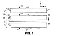
図1は本発明によるゾーン延伸装置の一実施形態の平面図である。装置は、ダウン−ウェブ方向を矢印8で表されるウェブパスを画定する一連のベルト10、20、および30を含む。ウェブパスに沿って移動するウェブは最外ベルト10および30によって画定されるようなウェブパスより実際には幅広いかもしれないが、ウェブパスは最外ベルト10および30によって画定される側面をウェブパスの縁上に含む。ダウン−ウェブ方向を画定することに加えて、矢印8はまた、ダウン−ウェブ方向に対して横断するクロス−ウェブ方向を画定するために用いることもできる。
FIG. 1 is a plan view of an embodiment of a zone stretching apparatus according to the present invention. The apparatus includes a series of
使用中に、ベルト10は、その上面18が矢印8の方向に移動するが、その下面(図示せず)は反対方向に移動するように回転する。ベルト10は投入端12と排出端14とを含む。同様に、ベルト20は、矢印8の方向に移動する上面28および反対方向に移動する下面(図示せず)の付いた、投入端22と排出端24とを含む。同様に、ベルト30は、矢印8の方向に移動する上面38および反対方向に移動する下面(図示せず)の付いた、投入端32と排出端34とを含む。
In use, the
同時に、ベルト10、20および30の投入端と排出端とは、ベルトによって画定されるウェブパスの相当する投入端と排出端とを画定する。また、x軸が矢印8で描かれるダウン−ウェブ方向に揃い、y軸が(ダウン−ウェブ方向に対して直角の)クロス−ウェブ方向に揃って、直交するxおよびy基準軸が図1に見られる。図1には見られないが、第3基準軸、すなわち、z軸がxおよびy基準軸の両方に垂直である基準軸として画定され得ることが理解されるであろう。z軸は図2〜5に関連して描かれている。
At the same time, the input and discharge ends of
ウェブパスに沿ったベルト10、20、および30の配置は、ベルト10がゾーンIを画定し、ベルト20がゾーンIIIを画定し、ベルト30がゾーンVを画定して、ウェブパス内ゾーンを画定するとして特徴づけることができる。必ずしも必要とはされないが、少なくとも幾らかの分離または空間が隣接ベルト間に提供されることが好ましいかもしれない。描かれた実施形態では、ベルト10と20との間の空間はウェブパス中のゾーンIIを画定し、ベルト20と30との間の空間はウェブパス内でゾーンIVを画定する。ゾーンIIおよびIVは、典型的には、ウェブパス内の延伸ゾーン、すなわち、加工中にすべてのまたは実質的にすべての延伸が起こるゾーンとして機能する。ゾーンのそれぞれはウェブパスの幅の一部を占めるとして説明することができ、好ましくは投入端から排出端まで、ウェブパスの長さにわたって伸びている。
The placement of
典型的には、それぞれのそれらのゾーンが5ミリメートル以上のクロス−ウェブ幅を有して、ゾーンIIおよびIV内ウェブのすべてが延伸される。ゾーンIIおよびIVが同時に延伸されることは好ましいかもしれないが、必要とされない。あるいはまた、ゾーンIIおよびIVの1つのみが活性化されてもよい。 Typically, each of those zones has a cross-web width of 5 millimeters or greater, and all of the zones II and IV webs are stretched. While it may be preferable for Zones II and IV to be stretched simultaneously, it is not required. Alternatively, only one of zones II and IV may be activated.
本発明をリングローリングのような従来の延伸法と比較した時に、本発明が特徴づけられることができる一つのやり方は歪み速度の観点からである。本明細書で用いるところでは、(歪みが延伸前の物品の元の長さで割った物品の長さの変化として測定されるので)歪みはそれ自体次元なしの単位であると理解して、歪み速度は単位時間当たりの歪みである。本発明に関しては、歪み速度は次の方程式により測定されてもよい。
(長さの変化/元の長さ)/(延伸距離/ライン速度)
One way in which the present invention can be characterized when compared to conventional stretching methods such as ring rolling is in terms of strain rate. As used herein, it is understood that strain is itself a unit without dimensions (since strain is measured as a change in the length of the article divided by the original length of the article before stretching) The strain rate is a strain per unit time. For the present invention, the strain rate may be measured by the following equation:
(Change in length / original length) / (stretching distance / line speed)
例えば、ウェブ中ゾーンが100%だけ延伸されることになっている場合、すなわち、長さの変化が元の長さに等しい(従って、延伸方向に物品の長さを2倍にする)場合、本発明の方法および装置を用いた歪み速度は、ライン速度が20メートル/分である時は100/分以下、より好ましくはライン速度が20メートル/分である時は50/分以下に制限されるかもしれない。本発明の方法および装置は、0.2メートル以上の延伸距離にわたってかかる歪み速度を達成することができる。 For example, if the zone in the web is to be stretched by 100%, that is, if the change in length is equal to the original length (thus doubling the length of the article in the stretch direction) The strain rate using the method and apparatus of the present invention is limited to 100 / min or less when the line speed is 20 meters / min, more preferably 50 / min or less when the line speed is 20 meters / min. It may be. The method and apparatus of the present invention can achieve such strain rates over stretch distances of 0.2 meters or more.
比較して言えば、3.3ミリメートル(0.14インチ)のオーバーラップおよび3.8ミリメートル(0.15インチ)のピーク−ピーク溝ピッチの噛み合い段ロールを用いるリングローリング法(例えば、ウェーバーらに付与された米国特許第5,143,679号明細書を参照されたい)は、同じ延伸距離、および、従って20メートル/分のライン速度で100/分の歪み速度を達成するために38メートル(125フィート)の直径のロールを必要とするであろう。当該サイズのロールは、公知の工学原理に従った安全なおよび/または効果的なやり方でまたは実現可能な経済学で構築および操作するのは本質的に不可能であることが理解されるであろう。 In comparison, a ring rolling method (e.g., Weber et al.) Using a 3.3 millimeter (0.14 inch) overlap and a 3.8 millimeter (0.15 inch) peak-to-peak groove pitch meshing step roll. U.S. Pat. No. 5,143,679) to 38 meters to achieve a strain rate of 100 / min at the same stretch distance, and thus a line speed of 20 meters / min. A roll of (125 feet) diameter would be required. It will be appreciated that a roll of that size is essentially impossible to construct and operate in a safe and / or effective manner or in a feasible economics according to known engineering principles. Let's go.
本発明の方法および装置は、比較的低いライン速度で、例えば、リングローリングより著しく低い歪み速度を提供するが、歪み速度の低下はライン速度が増加するにつれてより明白になる。例えば、ウェブが100%だけ延伸されることになっている時、本発明の方法および装置を用いた歪み速度は、ライン速度が100メートル/分である時に500/分以下に、より好ましくはライン速度が100メートル/分である時に250/分に制限されるかもしれない。3.3ミリメートル(0.13インチ)のオーバーラップおよび3.8ミリメートル(0.15インチ)のピーク−ピーク・ピッチで0.2メートル(8インチ)の直径を有する噛み合い段ロール付きの従来のリングローリング装置を同じライン速度で作動させると、1100/分を超える歪み速度をもたらすであろう。この高められた歪み速度は、主に、従来のリングローリング装置によって提供される短い延伸距離のためである。 While the method and apparatus of the present invention provides a strain rate that is significantly lower than, for example, ring rolling, at relatively low line speeds, the decrease in strain rate becomes more pronounced as the line speed increases. For example, when the web is to be stretched by 100%, the strain rate using the method and apparatus of the present invention is less than 500 / min, more preferably the line when the line speed is 100 meters / min. It may be limited to 250 / min when the speed is 100 meters / min. Conventional with interlocking step rolls having a diameter of 0.2 meters (8 inches) with an overlap of 3.3 millimeters (0.13 inches) and a peak-peak pitch of 3.8 millimeters (0.15 inches) Operating the ring rolling device at the same line speed will result in strain rates in excess of 1100 / min. This increased strain rate is mainly due to the short stretch distance provided by conventional ring rolling equipment.
歪み速度はライン速度に比例する速度で増加する。本発明に関連して、歪み速度はライン速度に一次比例する速度で増加するかもしれない。対照的に、リングローリング法の歪み速度はライン速度に一次比例しない速度で増加する。結果として、より速いライン速度は、本発明の方法および装置とリングローリング法との間にさらにより劇的な差をもたらすことができる。例えば、本発明は、ライン速度が300メートル/分である時に1500/分以下の歪み速度、好ましくは、ライン速度が300メートル/分である時に750/分以下の歪み速度を提供することができる。 The strain rate increases at a rate proportional to the line speed. In the context of the present invention, the strain rate may increase at a rate that is linearly proportional to the line rate. In contrast, the strain rate of the ring rolling method increases at a rate that is not linearly proportional to the line speed. As a result, higher line speeds can lead to even more dramatic differences between the method and apparatus of the present invention and the ring rolling method. For example, the present invention can provide a strain rate of 1500 / min or less when the line speed is 300 meters / min, and preferably a strain rate of 750 / min or less when the line speed is 300 meters / min. .
歪み速度はまた延伸距離に反比例し、延伸距離の増加はより低い歪み速度をもたらす。例えば、0.2メートル以上の延伸距離を有する本発明の方法および装置は、ライン速度が20メートル/分である時に100/分もしくはそれ未満、ライン速度が100メートル/分である時に500/分もしくはそれ未満、またはライン速度が300メートル/分である時に1500/分の歪み速度を提供することができる。別のセットの例では、0.4メートル以上の延伸距離を有する本発明の方法および装置は、ライン速度が20メートル/分である時に50/分もしくはそれ未満、ライン速度が100メートル/分である時に250/分もしくはそれ未満、またはライン速度が300メートル/分である時に750/分の歪み速度を提供することができる。 The strain rate is also inversely proportional to the stretch distance, and increasing the stretch distance results in a lower strain rate. For example, the method and apparatus of the present invention having an extension distance of 0.2 meters or more is 100 / min or less when the line speed is 20 meters / minute and 500 / minute when the line speed is 100 meters / minute. Alternatively, a strain rate of 1500 / min can be provided when the line speed is 300 meters / min or less. In another set of examples, the method and apparatus of the present invention having an extension distance of 0.4 meters or more is 50 / min or less when the line speed is 20 meters / minute, and the line speed is 100 meters / minute. It can provide a strain rate of 250 / min or less at some time, or 750 / min when the line speed is 300 meters / min.
次の表は、本発明を用いて達成されうる様々な距離およびライン速度で100%延伸について歪み速度(毎分)の範囲を提供する。本発明の幾つかの実施形態では一次の関係は提供されないことがあるが、表の値から分かるように関係は一次であることが好ましいであろう。 The following table provides a range of strain rates (per minute) for 100% stretch at various distances and line speeds that can be achieved using the present invention. Although some embodiments of the present invention may not provide a first order relationship, it may be preferred that the relationship is first order as can be seen from the values in the table.

本発明の方法および装置が特徴づけられることができる別のやり方は延伸距離によるものである。例えば、本発明は、任意の所望の長さ、例えば、0.2メートル以上、0.5メートル以上、0.75メートル以上などの延伸距離を提供することができる。当該延伸距離内で、(例えば、ウェブが実質的にその全幅の端から端まで延伸される幅出し法および装置とは対照的に)ウェブの一部のみが活性化または延伸される。選択された延伸距離範囲内で、選択されたゾーンのみでの事実上任意の選択された量(例えば、100%)の活性化または延伸が達成されることができる。 Another way in which the method and apparatus of the present invention can be characterized is by stretch distance. For example, the present invention can provide any desired length, for example, a stretch distance of 0.2 meters or more, 0.5 meters or more, 0.75 meters or more. Within that stretch distance, only a portion of the web is activated or stretched (eg, as opposed to a tentering method and apparatus in which the web is stretched across its full width). Within the selected stretch distance range, virtually any selected amount (eg, 100%) of activation or stretching in only the selected zone can be achieved.
対照的に、3.3ミリメートル(0.13インチ)のオーバーラップおよび3.8ミリメートル(0.15インチ)のピーク−ピーク・ピッチの噛み合い段ロールを用いて100%延伸を提供するリングローリング法は、0.2メートルの延伸距離を達成するために38メートル(125フィート)の直径、または0.4メートルの延伸距離を達成するために114メートル(375フィート)の直径のロールを必要とするであろう。当該サイズのロールは、公知の工学原理に従った安全なおよび/または効果的なやり方でまたは実現可能な経済学で構築および操作するのは本質的に不可能である。 In contrast, a ring rolling process that provides 100% stretch using 3.3 millimeter (0.13 inch) overlap and 3.8 millimeter (0.15 inch) peak-to-peak pitch meshing step rolls. Requires a roll of 38 meters (125 feet) diameter to achieve a 0.2 meter stretch distance or 114 meters (375 feet) diameter to achieve a 0.4 meter stretch distance Will. Such sized rolls are essentially impossible to construct and operate in a safe and / or effective manner according to known engineering principles or with feasible economics.
本発明の方法および装置は、あるいはまた、延伸ゾーンの幅とそれらを取り囲むゾーンとの関係によって特徴づけられることができる。本質的に、未延伸ゾーンは延伸されたゾーンの幅以上である幅を有することが好ましいことがある。これは、未延伸ゾーンが2つの延伸されたゾーン(そこではウェブのすべてが延伸されている)間に置かれている場合に特に当てはまる。例えば、ゾーンII内ウェブの部分が延伸されている5ゾーンウェブでは、ゾーンIはゾーンIIの幅以上である幅を好ましくは有してもよい。ゾーンIIIがゾーンIIの幅以上である幅を有すること、かつ、さらに、ゾーンIIIがゾーンIV(ここでゾーンIVもまた延伸されたゾーンである)の幅以上である幅を有することもまた好ましいかもしれない。ゾーンVがゾーンIVの幅以上である幅を有することがさらに好ましいことがある。 The method and apparatus of the present invention can alternatively be characterized by the relationship between the width of the stretching zones and the surrounding zones. In essence, it may be preferred that the unstretched zone has a width that is greater than or equal to the width of the stretched zone. This is especially true when the unstretched zone is located between two stretched zones where all of the web is stretched. For example, in a five-zone web where the portion of the web in Zone II is stretched, Zone I may preferably have a width that is greater than or equal to the width of Zone II. It is also preferred that Zone III has a width that is greater than or equal to the width of Zone II, and that Zone III has a width that is greater than or equal to the width of Zone IV (where Zone IV is also a stretched zone). It may be. It may be further preferred that zone V has a width that is greater than or equal to the width of zone IV.
描かれた装置はウェブパスの幅にわたって配置された5ゾーンを含むが、本発明は3ほどに少ないゾーンで行われてもよいことが理解されるであろう。例えば、ベルト10および20がベルト30なしで用いられ、ゾーンI、II、およびIIIによって画定されるウェブパスをもたらすことができよう。ウェブパスの幅の端から端まで配置された5より多いゾーンを有するウェブパスが提供されてもよいこともまた理解されるべきである。
Although the depicted apparatus includes five zones arranged across the width of the web path, it will be appreciated that the invention may be practiced with as few as three zones. For example,
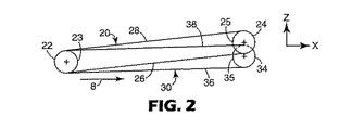
図2は、図1のライン2−2に沿った図1の装置の断面図である。ベルト20がプーリー23および25にわたって張られて、ベルト20はその投入端22にプーリー23とその排出端24にプーリー25とを含む。ベルト20は上面28および下面26を含み、ベルト20がプーリー23および25の回りを回転する時に該2面は反対方向に移動する。投入端および排出端のプーリーは同様な直径を有するとして描かれているが、プーリーのサイズが異なってもよいことは理解されるべきである。
2 is a cross-sectional view of the apparatus of FIG. 1 taken along line 2-2 of FIG.
それはベルト20とそのプーリー23および25とによって部分的に隠されるので、ベルト30の投入端(およびその関連プーリー)はベルト20の投入端22およびそのプーリー23の後ろに隠されて、ベルト30およびその支持構造物の一部のみが図2に示されている。しかしながら、ベルト30の排出端34は、ベルト30の排出端34に置かれているプーリー35と一緒に図2で見られる。ベルト30の下面36および上面38の両方もまた図2で見られ、該2面は装置の運転中に反対方向に移動する。
Since it is partially hidden by the
ベルト20の排出端24はベルト30に対してz軸方向に幾らかの変位を有するとして示されている。本明細書で図3〜5に関してより詳細に記載されるように本装置によって加工されるウェブの延伸を提供するのは当該変位である。典型的には、投入端でベルトのすべての相対位置を維持しながら、その排出端でベルトの一端のみを変位させることが好ましいであろう。
The
ベルト20および30はz軸で互いに変位しているので、ある場合には、一ベルトをより速いまたはより遅い速度で作動させて異なるゾーンの異なるウェブパス長さに調節することが望ましいかもしれない。例えば、図1および2に描かれているもののような装置では、ゾーンIII内ウェブパス長さはゾーンIおよびV内ウェブパス長さとは異なる。結果として、ゾーンIおよびIIIのベルト10および30と比べて僅かにより高いダウン−ウェブ速度でベルト20を作動させることが望ましいかもしれない。あるいはまた、異なるゾーンでのウェブ速度の何の調節も必要とされないようにゾーンのすべてが同じ(またはほぼ同じ)パス長さを有するように異なるゾーンでのウェブパス長さを修正することが望ましいことがある。
Since
本発明の装置は、回転するプーリーの周りに巻かれた連続ベルトの使用を当てにしているように描かれているが、他の代替構造物が連続ベルトの代わりに用いられてもよいことは理解されるであろう。例えば、間隔を開けずにローラーを配置できるように比較的小さい直径を好ましくは有してもよい一連のローラーが用いられてもよい。他の場合には、加工中にウェブを支持および/または保持するためにローラーを他の構造物と組み合わせた連続ベルトを用いることが可能であることがある。 Although the device of the present invention is depicted as relying on the use of a continuous belt wound around a rotating pulley, it is understood that other alternative structures may be used in place of the continuous belt. Will be understood. For example, a series of rollers may be used that may preferably have a relatively small diameter so that the rollers can be placed without spacing. In other cases, it may be possible to use a continuous belt that combines rollers with other structures to support and / or hold the web during processing.
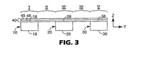
図3は、ウェブ40がウェブパスに沿って置かれ、ウェブ40がそれぞれベルト10、20、および30の上面18、28、および38と接触している、図1の端面図である。図3には、yおよびz基準軸の両方に加えてゾーンI、II、III、IV、およびVもまた描かれている。
FIG. 3 is an end view of FIG. 1 with the web 40 positioned along the web path and the web 40 in contact with the
図3に見られるような図は、1つまたは複数のベルトの任意の変位がz軸方向に与えられる前に取られたものである。この配置では、ベルトおよびそれらのそれぞれのゾーンは互いに対してニュートラル位置にある、すなわち、何のクロス−ウェブ延伸もウェブ40中に誘発中ではないとして記載することができる。 The view as seen in FIG. 3 was taken before any displacement of one or more belts was applied in the z-axis direction. In this arrangement, the belts and their respective zones can be described as being in a neutral position relative to each other, i.e., no cross-web stretching is being induced in the web 40.
ウェブ40は、(図3に見られるようにクロス−ウェブ方向がy軸に相当して)クロス−ウェブ方向の延伸が望ましい任意のウェブであることができる。描かれたウェブ40は、第1層45および第2層46を含むラミネートである。第1および第2層45および46は、同じものであっても異なるものであってもよい。層46がウェブ40に弾性を与えることができるように第2層46は弾性材料(例えば、シート、フィラメント、ストランドなど)を含むことが好ましいことがある。第1層45は非弾性(例えば、不織材料)であることが好ましいことがある。好ましい一ウェブ40は、延伸前にウェブ40が全体としては実質的に非弾性であるように、弾性層46に積層された非弾性層45を含んでもよい。
The web 40 can be any web where stretching in the cross-web direction is desired (corresponding to the y-axis as seen in FIG. 3). The depicted web 40 is a laminate that includes a
延伸の結果として、非弾性層内の結合が破損されまたは別のやり方で分断され、それによって層46の弾性を延伸されるゾーン内に行き渡るようにするので、ウェブ40は延伸されるゾーン内で弾性になることができる。本明細書で説明されるように、延伸されるゾーンは、ゾーンの潜在的な弾性が活性化されたことを示すために活性化ゾーンと記載されてもよい。
As a result of stretching, the bond in the inelastic layer is broken or otherwise broken, thereby allowing the elasticity of the
ウェブ40は多層構造物として描かれているが、ウェブ40が所望に応じて、任意の数の層、構造物、材料などを含んでもよいことは理解されるであろう。さらに、ウェブ40の部分は全く非弾性であってよい、すなわち、ウェブ40の部分はいかなる有意な量の弾性材料も含まなくてよい。例えば、ウェブ40はゾーンI、III、およびVの区域に非弾性ウェブ成分とゾーンIIおよびIVの区域に不織/弾性ウェブ・ラミネートとを含むことが好ましいことがある。多成分ウェブの別の例は、図10に関連して下に記載される。 Although the web 40 is depicted as a multi-layer structure, it will be understood that the web 40 may include any number of layers, structures, materials, etc. as desired. Furthermore, the portion of the web 40 may be totally inelastic, i.e. the portion of the web 40 may not contain any significant amount of elastic material. For example, web 40 may preferably include a non-elastic web component in zones I, III, and V and a non-woven / elastic web laminate in zones II and IV. Another example of a multi-component web is described below in connection with FIG.
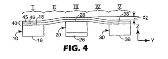
図4は、図3に見られるような、しかしながら、距離dz上方へz軸方向にベルト20が変位した装置の端面図である(変位の側立面図については図2を参照されたい)。該図は装置の排出端から取られており、ベルト20の投入端はベルト10および30の投入端と位置合せしたままであるから、ベルト20の下面26は図4に見られる。
FIG. 4 is an end view of the device as seen in FIG. 3, however, with the
z軸方向でのベルト20の排出端24の変位の結果として、ゾーンII〜IV内ウェブ40は(ベルト10および30上の)ゾーンIおよびV中のウェブ40の部分と比べて持ち上げられている。当該変位で、ベルト10の縁と20の縁との間の距離は(ベルト20の淵と30の淵との間の距離と同様に)増えており、ベルト20がz軸方向に変位しているのでゾーンIIおよびIV内ウェブ40の部分は延伸される。示されたもののような非接触延伸方法および装置では、ゾーンII内ウェブはゾーンIおよびIIIにおけるベルト10と20との間のz−方向高さの差を埋める。同様に、ゾーンIV内ウェブはゾーンIIIおよびVにおけるベルト20と30との間のz−方向高さの差を埋める。
As a result of the displacement of the discharge end 24 of the
図2および4に見られるように排出端24が変位している場合ベルト10および30に対するベルト20の緩やかな勾配のためにウェブ40上のポイントが装置の投入端から排出端へ移動するにつれてウェブ40に誘発される歪みの量は徐々に増加する。ベルトが図2に見られるような投入端と排出端との間の真っ直ぐなパスを移動する場合、投入端から排出端への歪みの変動は一次として説明されてもよい。
When the
図2はまた、延伸距離、すなわち、ウェブの選択されたゾーンが延伸される距離をも例示する。典型的には、延伸距離はベルト10、20、および30の投入端12、22、および32と排出端14、24、および34との間の距離によって画定される。
FIG. 2 also illustrates the stretch distance, i.e. the distance by which a selected zone of the web is stretched. Typically, the stretch distance is defined by the distance between the input ends 12, 22, and 32 and the discharge ends 14, 24, and 34 of the
当該延伸距離は、ある場合には、好ましくはウェブの延伸されるゾーンの幅以上であるかもしれない。それ故、例示された方法および装置では、延伸距離は好ましくはゾーンIIおよびIVの幅以上であることができる。あるいはまた、延伸距離は全体としてウェブの幅以上であることが好ましいことがある。延伸距離を特徴づける別のやり方では、延伸距離はウェブ中の延伸されたゾーンの少なくとも1つの幅の2倍ほどに大きいまたはそれ以上であることが好ましいことがある。例えば、描かれた実施形態では、延伸距離はゾーンIIの幅の2倍以上ほど大きいことが好ましいことがある。ある場合には、延伸距離と延伸されたゾーンの少なくとも1つの幅との間の関係は、延伸距離が関連延伸ゾーンの幅の4倍以上であるようなものである。例えば、描かれた実施形態では、延伸距離はゾーンIIの幅の4倍以上ほど大きいことが好ましいことがある。 The stretching distance may in some cases preferably be greater than or equal to the width of the stretched zone of the web. Thus, in the illustrated method and apparatus, the stretch distance can preferably be greater than or equal to the width of zones II and IV. Alternatively, it may be preferred that the stretch distance as a whole is greater than or equal to the width of the web. In another way of characterizing the stretch distance, it may be preferred that the stretch distance is as large as or greater than twice the width of at least one of the stretched zones in the web. For example, in the depicted embodiment, it may be preferred that the stretch distance be greater than twice the width of Zone II. In some cases, the relationship between the stretch distance and at least one width of the stretched zone is such that the stretch distance is greater than or equal to 4 times the width of the associated stretch zone. For example, in the depicted embodiment, it may be preferable for the stretch distance to be greater than four times the width of Zone II.
図4に描かれた装置で、ベルト10、20、および30はそれらの表面上に、ウェブ40をベルト表面と接触して保持するための役割を果たす、ある構造物または材料を含むことが好ましいことがある。例えば、ベルト表面は、加工中に補充ウェブ40をその上に保持するフックおよびループ構造物の一部のような機械構造物を含んでもよい。あるいはまた、ベルト10、20、および30は、接着剤、磁気力などを含むが、それらに限定されない他の技術によってウェブ40を保持してもよい。他の場合には、ウェブ40とベルト10、20、および30との間の摩擦係数を上げる材料、例えば、研磨材、ゴムなどが使用されてもよい。さらに他の代替案は、その上にウェブを保持するそれらの能力を改善するためにベルト10、20、および30上に突き出たピン、支柱、ピラミッドなどのような構造物を提供することを伴うことがある。
In the apparatus depicted in FIG. 4, the
図5は、図3および4の、しかしながら、距離dz上方へz軸方向にベルト20がさらに変位した装置の端面図である。図5に見られる図は装置の排出端の図であるから、ベルト20の下面26もまた図5に見られる。隣接するベルト10および30に対してz軸方向でのベルト20の増加した変位は、(図4で提供される歪みの量と比べて)ゾーンIIおよびIV内ウェブ40の増加した歪みをもたらす。
FIG. 5 is an end view of the apparatus of FIGS. 3 and 4, however, with the
図3〜5間で隣接するベルト10および30に対するベルト20の変位の変更はまた、本発明による方法の調節可能性をも例示する。例えば、ベルト10、20、および30が(ベルトが一線上に揃っている)図3に見られるようなそれらのニュートラル位置にある間に装置にウェブを容易に装着することができ、ウェブ40がダウン−ウェブ方向に移動するにつれて変位を徐々に増やすことができる。さらに、ウェブ40がダウン−ウェブ方向に移動中である間にベルト10および30の1つまたは両方に対するベルト20の変位を調節してウェブ40のゾーン中で誘発される歪みの量を調節することができる。
Changing the displacement of the
図6は、図4および5に描かれるような延伸に関連した力が取り除かれた後、従って延伸されたゾーンを緩和させた後のウェブ40の拡大断面図である。ウェブ40は層45および46を含み、上述されたようなゾーンI〜Vによって画定され得る。ゾーンIIおよびIV、すなわち、ウェブ40が図4および5に描かれるように延伸されたゾーンでは、ウェブ40は、延伸されたゾーンが今や弾性である場合、図6に描かれるように幾らかのギャザリングまたは皺を示すことがある。
FIG. 6 is an enlarged cross-sectional view of the web 40 after the stretching-related forces as depicted in FIGS. 4 and 5 have been removed and thus have relaxed the stretched zone. Web 40 includes
図6に関連して、1つまたは複数の延伸されたゾーンを含む本発明によるウェブを特徴づけることが可能であろう。かかるウェブ40は不定の長さ、すなわち、その幅よりはるかに大きい長さを有してもよく、例えば、ロールに集められても変換工程へ直ちに導かれてもよく、変換工程でウェブ40は別の製品中へ組み入れるために、細長く切る、シートにするなどができる。本発明によって製造されたウェブは、それらの延伸されたゾーンの観点から特徴づけられるであろう。例えば、本発明によるウェブは、緩和状態にある時に(延伸力を取り除いた後に)延伸されたゾーンの少なくとも1つがクロス−ウェブ方向に5ミリメートル以上、ある場合には10ミリメートル以上の幅を有して、1つまたは複数の延伸されたゾーンを含んでもよい。
In connection with FIG. 6, it would be possible to characterize a web according to the invention comprising one or more stretched zones. Such a web 40 may have an indefinite length, i.e. a length much greater than its width, for example it may be collected on a roll or immediately led to a conversion process, where the web 40 is It can be cut into strips, sheets, etc. for incorporation into another product. Webs produced according to the present invention will be characterized in terms of their stretched zones. For example, a web according to the present invention has a width of at least one of the stretched zones when in a relaxed state (after removing the stretching force) in the cross-web direction of 5 millimeters or more, and in some
延伸ゾーン内のウェブのすべてが延伸される。当該特徴は、本発明のウェブ中の延伸されたゾーンを、噛み合い歯と接触しているウェブの部分が加工中に典型的には延伸されず、こうしてより大きな延伸されたゾーン内に小さな区域を延伸されないままにするリングロールされたウェブから区別する。 All of the web in the stretching zone is stretched. The feature is that the stretched zone in the web of the present invention is such that the portion of the web that is in contact with the meshing teeth is not typically stretched during processing, thus creating a small area within the larger stretched zone. Distinguish from ring-rolled webs that remain unstretched.
さらに、本明細書でまた記載されるように、何の延伸も行われないゾーンは、延伸ゾーンと同じかまたはそれより幅広くてもよい。また、何の延伸も提供されないゾーンの反対側に2つの延伸ゾーンが提供されてもよい。例えば、ウェブ40のゾーンII〜IVを参照されたい。かかる実施形態では、ゾーンのすべて、すなわち、2つの延伸されたゾーンおよび中間ゾーンは5ミリメートル以上の幅を有してもよい。 Further, as also described herein, the zone where no stretching is performed may be the same as or wider than the stretching zone. Also, two stretching zones may be provided on the opposite side of the zone where no stretching is provided. For example, see Zones II-IV of web 40. In such an embodiment, all of the zones, i.e. the two stretched zones and the intermediate zone, may have a width of 5 millimeters or more.
例えば、上に記載されたウェブ40のようなウェブ中の延伸されたゾーンが延伸後に弾性を示す場合、ゾーンは本発明の原理内で「活性化された」ゾーンと言われてもよい。しかしながら、ある場合には、本発明のウェブ中の延伸されたゾーンは延伸後に弾性を示さないかもしれない。かかるゾーンは、例えば、分子配向、薄化などを提供するために延伸されてもよい。 For example, if a stretched zone in a web, such as web 40 described above, exhibits elasticity after stretching, the zone may be referred to as an “activated” zone within the principles of the present invention. However, in some cases, the stretched zone in the web of the present invention may not exhibit elasticity after stretching. Such zones may be stretched, for example, to provide molecular orientation, thinning, and the like.
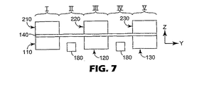
図7および8は、本発明に従った代替装置を描いている。図7および8に描かれた装置は、多くの点で、図1〜5に描かれた装置に似ている。装置はまた、クロス−ウェブ方向にウェブパスの部分を占める一連のゾーンを画定するベルトを含む。 7 and 8 depict an alternative device according to the present invention. The device depicted in FIGS. 7 and 8 is similar in many respects to the device depicted in FIGS. The apparatus also includes a belt that defines a series of zones that occupy a portion of the web path in the cross-web direction.
しかしながら、図7および8の装置は、ゾーンI、IIIおよびVのそれぞれ内ウェブ140を固定するまたは別のやり方で制約する対向ベルトのペアを含む。例えば、ゾーンIでのベルト110および210はゾーンI内ウェブ140の部分を固定して2つのベルトの間にウェブ140を保持する。同様に、下方ベルト120は上方ベルト220と組み合わせてゾーンIII内ウェブ140を保持する。同様に、下方ベルト130は上方ベルト230と組み合わせてゾーンV内ウェブ140を固定する。図1〜5の装置でのように、ウェブ140のゾーンIIおよびIVは、ベルトによって制約されないまたはいかなるベルトとも接触していない。
However, the apparatus of FIGS. 7 and 8 includes a pair of opposing belts that secure or otherwise constrain the
図8は、ウェブ140のゾーンIIIが下方ベルト120および上方ベルト220によってz軸方向に変位させられた図7の装置を描いている。ゾーンIIおよびIV内ウェブは、下方ベルト110および上方ベルト210によるゾーンI内ウェブ140の保持のために延伸される。同様に、ゾーンIIIの反対側で、ベルト130および230は、ゾーンIIおよびIV内ウェブ140の延伸中にゾーンV内ウェブを制約する。
FIG. 8 depicts the apparatus of FIG. 7 with zone III of
ゾーンI、III、およびVのそれぞれ内ウェブの部分は対向ベルトのペア間圧力によって専ら制約されてもよいが、ゾーンI、III、およびVのそれぞれ中の上方および下方ベルトの1つまたは両方が対向ベルトのペア間にウェブ140を保持するのを支援する構造物または材料を含んでもよい。
The portion of the inner web in each of zones I, III, and V may be constrained exclusively by the pressure between the pair of opposing belts, but one or both of the upper and lower belts in each of zones I, III, and V It may include structures or materials that assist in holding the
さらに、対向ベルトのペア間圧力は、様々な技術によって発生させられてもよい。例えば、ある場合には、ベルトの投入端と排出端との間に何の中間支持構造物も提供されずに、ベルト張力によってもたらされる圧力が十分であろう。他の場合には、装置の運転中に対向ベルト間に固定されるウェブへの十分な圧力を維持するためにベルトの投入端と排出端との間にある中間支持体を提供することが望ましいこともある。かかる中間支持体は、静的構造物(例えば、ボルトがそれを乗り越える表面)または動的構造物(例えば、中間支持ローラー)の形をとってもよい。 Further, the pressure between the pair of opposing belts may be generated by various techniques. For example, in some cases, the pressure provided by the belt tension may be sufficient without providing any intermediate support structure between the input and output ends of the belt. In other cases, it may be desirable to provide an intermediate support between the input and output ends of the belt to maintain sufficient pressure on the web that is secured between the opposing belts during operation of the device. Sometimes. Such intermediate supports may take the form of static structures (eg, surfaces over which bolts ride) or dynamic structures (eg, intermediate support rollers).
例えば、加工中にゾーンIIおよびIV内ウェブ140の温度を制御するために配置されてもよい温度制御装置180もまた図7および8に描かれている。温度制御装置180は所望に応じて延伸中にウェブ140を加熱および/または冷却するために用いられてもよい。
For example, a
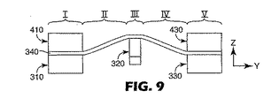
図9は、ゾーンIに一対の対向ベルト310および410ならびにゾーンVに一対の対向ベルト330および430を含む別の代替装置を描いている。ゾーンIおよびV内ウェブ340の部分に比べてウェブ340をz軸方向に変位させるために用いられるより狭いゾーンIII内ベルト320がペアの対向ベルト間に置かれる。図9に見られる配置では、ゾーンIII内ウェブ340を制約することは必要でないかもしれないが、ゾーンIIおよびIV内ウェブ340の部分は、ゾーンIIIでのウェブ340の変位のために延伸される。
FIG. 9 depicts another alternative device that includes a pair of opposing
図9に描かれた一態様は、ベルトおよびウェブ中のそれらの相当するゾーンのすべてがサイズの点で一様である必要はないことである。クロス−ウェブ方向でのゾーンの幅は必要に応じてゾーン毎に変わることができる。図9に描かれる別の態様は、より狭いウェブゾーン(例えば、図9のゾーンIII)に生じ得るより大きい力のために、より狭いゾーンがウェブをその中に保持または制約するために固定を必要としないかもしれないことである。 One aspect depicted in FIG. 9 is that not all of their corresponding zones in the belt and web need be uniform in size. The width of the zone in the cross-web direction can vary from zone to zone as required. Another aspect depicted in FIG. 9 is that because of the greater force that can occur in a narrower web zone (eg, zone III in FIG. 9), the narrower zone can be locked to hold or constrain the web therein. It may not be necessary.
図10は、ウェブの一部を延伸するために用いられるウェブ加工装置60を他のウェブ加工装置とインラインで用いることができる概念を例示するブロック図である。例えば、ウェブ加工装置60は、例えば、加熱、冷却、カレンダー掛け、存在するウェブへの材料の塗布(例えば、ウェブへのホットメルトまたは感圧接着剤の塗布)などによって既存のウェブを例えば加工してもよい装置50の下流に置かれてもよい。ある場合には、装置50は(例えば、押出、回転接合、カーディング、メルトブローイング、製織、不織ウェブまたは他の非弾性ウェブの弾性ウェブへの積層などによって)ウェブを製造してもよく、次にウェブは本発明によるウェブ加工装置中へ導かれる。
FIG. 10 is a block diagram illustrating the concept that the
本発明によるウェブ加工装置60は、それ自体、ウェブの部分が本発明の原理により延伸された後のウェブに作用する別の加工装置70の上流に置かれてもよい。例えば、装置70は、1つまたは複数の場所でウェブを細長く切る、穴を開ける、および/または開口する、ウェブを圧延してシートにする、ウェブに接着剤を塗る、材料をウェブに積層する(例えば、フックのような機械ファスナー材料を取り付ける)、ダイカットするなどのために用いられてもよい。
The
装置70はまた、その間にウェブまたはウェブの部分が追加の処理を受けてもよい所望の滞留時間の間ウェブをその延伸された状態に維持するために用いられてもよい。例えば、管理されたやり方でウェブまたはウェブの部分の温度を上げるおよび/または下げることは望ましいであろう。滞留時間は、例えば、図1〜9に関して上に記載された装置によって誘発されるような延伸の一定レベルを維持するベルトまたは他の構造物を用いて保持されてもよい。
The
上で簡潔に触れたように、本発明は、均質な単層ウェブ、多層ウェブ、複合ウェブなどをはじめとする任意の好適なウェブを加工するために用いることができる。好適なウェブは、例えば、図6に単一の多層ウェブとして概略的に示される。本発明の装置および方法を用いて加工されてもよい複合ウェブの例は、図11に描かれる。図11のウェブ440は、(図11に描かれるウェブの断面図を持った)一緒に積層された様々な異なる成分の複合ウェブである。
As briefly mentioned above, the present invention can be used to process any suitable web, including homogeneous single layer webs, multilayer webs, composite webs, and the like. A suitable web is schematically illustrated, for example, as a single multilayer web in FIG. An example of a composite web that may be processed using the apparatus and method of the present invention is depicted in FIG.
上の図1〜8の装置に関連して記載されるゾーンに(便宜上)対応するウェブ440に関連して様々なゾーンが特定される。ウェブ440では、ゾーンIおよびVはそれぞれ基材442上に接着層441を含有する。図7および8の装置に関連して記載されたようにウェブ440を対向ベルト内に制約することによって、接着層441の完全性はより良く維持されるであろう。
Various zones are identified in relation to the web 440 (for convenience) corresponding to the zones described in connection with the apparatus of FIGS. 1-8 above. In
ウェブ440のゾーンIIIは、機械ファスナーに用いられる層443(例えば、ホックおよびループファスナー用のホック材料の層)を含有する。ゾーンIおよびVに見いだされる接着剤と同じように、その中に置かれた機械ファスナー材料443の完全性を維持するために、ウェブのゾーンIII内のいかなる有意量の延伸も防ぐことが望ましいであろう。
Zone III of
ウェブ440のゾーンIIおよびIVは、弾性材料の層446の両面上に非弾性カバー層445を含むラミネートを含有する(非弾性カバー層445は弾性材料446の層446の一面上に提供されるのみであってもよいことが理解されるけれども)。延伸されてそれらの非弾性結合を解除するまで、カバー層445は典型的にはダウン−ウェブおよびクロス−ウェブ方向の両方に弾性層446を制約するであろう。しかしながら、本発明の装置および/または方法を用いて加工された場合、カバー層445内の非弾性結合は分離され、それによってゾーンIIおよびIV内ウェブを層446の弾性のおかげでクロス−ウェブ方向に弾性にする。
Zones II and IV of
本発明の原理により処理した後、ウェブ440がゾーンIII内で分離され、それぞれが接着成分(ゾーンIまたはV)、弾性成分(ゾーンIIまたはIV)、および機械ファスナー成分(ゾーンIIIの一部)を含む2つのウェブをもたらすようにウェブ440をスリッターまたは他の分離装置中へ導くことができる。次に、これらのウェブを圧延してシートにし、子供のおむつ、成人失禁用具、寝具類(例えば、シーツ、枕ケースなど)、アパレルなどを含むが、それらに限定されない様々な製品で使用することができる。
After processing according to the principles of the present invention, the
先行する具体的実施形態は本発明の実施を例示する。本発明は、本文書に具体的に記載されない任意の要素またはアイテムがない場合に好適に実施されてもよい。 The preceding specific embodiments illustrate the practice of the present invention. The present invention may be suitably implemented in the absence of any element or item not specifically described in this document.
本発明の範囲から逸脱することなく本発明の様々な修正および変更が当業者には明らかになるであろうし、本発明が本明細書で述べられた例示的な実施形態に不当にも限定されるべきではないが、特許請求の範囲に述べられる制限およびそれら制限の任意の等価物によって規制されるべきであることは理解されるべきである。 Various modifications and alterations of this invention will become apparent to those skilled in the art without departing from the scope of this invention, and the present invention is unduly limited to the exemplary embodiments described herein. It should be understood that it is not to be limited by the limitations set forth in the claims and any equivalents of those limitations.
Claims (34)
該ウェブをダウン−ウェブ方向に前進させながら延伸距離にわたってクロス−ウェブ方向に該第2ゾーン内のウェブを延伸する工程であって、該延伸が該ダウン−ウェブ方向およびクロス−ウェブ方向の両方に垂直の延伸方向で該第1ゾーンの位置と第3ゾーンの位置を互いに対して変えることを含む工程と
を含むウェブの延伸方法であって、
該第2ゾーン内のウェブのすべてが延伸され、かつ、該第2ゾーンが該延伸前に5ミリメートル以上の幅を有する方法。 Advancing a web having a width in a cross-web direction transverse to the down-web direction in the down-web direction, the web further comprising first, second, and third zones; Each of the first, second, and third zones includes a portion of the width of the web and extends along the length of the web in a down-web direction, the second zone being the first zone A process placed between the third zone;
Stretching the web in the second zone in the cross-web direction over a stretch distance while advancing the web in the down-web direction, wherein the stretching is in both the down-web direction and the cross-web direction. A method of stretching the web comprising the steps of: changing the position of the first zone and the position of the third zone with respect to each other in a vertical stretching direction,
A method wherein all of the web in the second zone is stretched and the second zone has a width of 5 millimeters or more prior to the stretching.
該ウェブをダウン−ウェブ方向に前進させながら延伸距離にわたってクロス−ウェブ方向に該第2ゾーン内のウェブを延伸する工程であって、該延伸が該ダウン−ウェブ方向およびクロス−ウェブ方向の両方に垂直の延伸方向で該第1ゾーンの位置と第3ゾーンの位置を互いに対して変えることを含む工程と
を含むウェブの延伸方法であって、
該第2ゾーン内のウェブを100%だけ延伸する工程が20メートル毎分のライン速度でダウン−ウェブ方向に該ウェブを前進させている間に100毎分以下の歪み速度を誘発し、該歪み速度が該ライン速度に一次比例する速度で増加する方法。 Advancing a web having a width in a cross-web direction transverse to the down-web direction in the down-web direction, the web further comprising first, second, and third zones; Each of the first, second, and third zones includes a portion of the width of the web and extends along the length of the web in a down-web direction, the second zone being the first zone A process placed between the third zone;
Stretching the web in the second zone in the cross-web direction over a stretch distance while advancing the web in the down-web direction, wherein the stretching is in both the down-web direction and the cross-web direction. A method of stretching the web comprising the steps of: changing the position of the first zone and the position of the third zone with respect to each other in a vertical stretching direction,
Stretching the web in the second zone by 100% induces a strain rate of less than 100 per minute while advancing the web in the down-web direction at a line speed of 20 meters per minute, A method in which the speed increases at a speed that is linearly proportional to the line speed.
該ウェブをダウン−ウェブ方向に前進させながら延伸距離にわたってクロス−ウェブ方向に該第2ゾーン内のウェブを延伸する工程であって、該延伸が該ダウン−ウェブ方向およびクロス−ウェブ方向の両方に垂直の延伸方向で該第1ゾーンの位置と第3ゾーンの位置を互いに対して変えることを含む工程と
を含むウェブの延伸方法であって、
該第1ゾーンの位置を該第3ゾーンに対して変えることが該延伸距離にわたって延伸方向に該第3ゾーンに対して該第1ゾーンの位置の差を直線的に増加させることを含む方法。 Advancing a web having a width in a cross-web direction transverse to the down-web direction in the down-web direction, the web further comprising first, second, and third zones; Each of the first, second, and third zones includes a portion of the width of the web and extends along the length of the web in a down-web direction, the second zone being the first zone A process placed between the third zone;
Stretching the web in the second zone in the cross-web direction over a stretch distance while advancing the web in the down-web direction, wherein the stretching is in both the down-web direction and the cross-web direction. A method of stretching the web comprising the steps of: changing the position of the first zone and the position of the third zone with respect to each other in a vertical stretching direction,
Changing the position of the first zone relative to the third zone includes linearly increasing the difference in position of the first zone relative to the third zone in the direction of stretching over the stretch distance.
前記延伸距離にわたって前記第2ゾーン内のウェブを延伸する間、対向ベルト間に前記第3ゾーン内のウェブをクランプする工程と
をさらに含む、請求項1〜4のいずれか1項に記載の方法。 Clamping the web in the first zone between opposing belts while stretching the web in the second zone over the stretching distance;
The method of any one of claims 1 to 4, further comprising clamping the web in the third zone between opposing belts while stretching the web in the second zone over the stretching distance. .
該第1ゾーンおよび第3ゾーンが、該第1、第2、および第3ゾーンがクロス−ウェブ方向に位置合せされている互いに対してニュートラル位置を有し、
かつ、該第1ゾーンおよび第3ゾーンが、該第1および第3ゾーンがダウン−ウェブ方向およびクロス−ウェブ方向の両方に垂直である延伸方向に互いに変位している互いに対して延伸位置を有し、ウェブパスが、該第1ゾーンおよび第3ゾーンが該延伸方向に互いに対して変位している延伸距離を画定し、
かつ、さらに該ウェブパスの第2ゾーンが該第1ゾーンと第3ゾーンとの間に延びており、該延伸距離にわたってそれらの間で支持されていない
装置。 A web path comprising a down-web direction extending from the input end to the discharge end and a cross-web direction transverse to the down-web direction, wherein the web path comprises first, second and third zones. Further comprising: each of the first, second, and third zones includes a portion of the width of the web path and extends along the length of the web path in a down-web direction; A web stretching device comprising a web path positioned between the first zone and the third zone,
The first zone and the third zone have a neutral position relative to each other in which the first, second and third zones are aligned in the cross-web direction;
And the first zone and the third zone have stretch positions relative to each other that are displaced from each other in a stretch direction in which the first and third zones are perpendicular to both the down-web direction and the cross-web direction. The web path defines a stretch distance in which the first zone and the third zone are displaced relative to each other in the stretch direction;
And a device wherein the second zone of the web path extends between the first zone and the third zone and is not supported between them over the stretch distance.
該第2ゾーンが延伸されるゾーンを含み、かつ、該第2ゾーンが元の幅から延伸した後に5ミリメートル以上の幅を有し、かつ、さらに該第1ゾーンが該第2ゾーンの幅以上である幅を有する
ウェブ。 A web comprising an indefinite length and a cross-webwise width transverse to the length, the web further comprising first, second and third zones, wherein the first, second, And each of the third zones includes a portion of the width of the web and extends along the length of the web, and the second zone is located between the first zone and the third zone And
The second zone includes a zone to be stretched, and the second zone has a width of 5 millimeters or more after stretching from the original width, and the first zone is greater than or equal to the width of the second zone A web having a width that is.
Applications Claiming Priority (2)
| Application Number | Priority Date | Filing Date | Title |
|---|---|---|---|
| US10/318,570 US6938309B2 (en) | 2002-12-13 | 2002-12-13 | Zoned stretching of a web |
| PCT/US2003/033723 WO2004054785A1 (en) | 2002-12-13 | 2003-10-24 | Zoned stretching of a web |
Publications (2)
| Publication Number | Publication Date |
|---|---|
| JP2006509925A true JP2006509925A (en) | 2006-03-23 |
| JP2006509925A5 JP2006509925A5 (en) | 2006-10-26 |
Family
ID=32506394
Family Applications (1)
| Application Number | Title | Priority Date | Filing Date |
|---|---|---|---|
| JP2004560299A Pending JP2006509925A (en) | 2002-12-13 | 2003-10-24 | Web zone stretching |
Country Status (12)
| Country | Link |
|---|---|
| US (2) | US6938309B2 (en) |
| EP (1) | EP1569785A1 (en) |
| JP (1) | JP2006509925A (en) |
| KR (1) | KR20050085644A (en) |
| CN (1) | CN100341689C (en) |
| AR (1) | AR042365A1 (en) |
| AU (1) | AU2003286652A1 (en) |
| BR (1) | BR0317078A (en) |
| MX (1) | MXPA05006075A (en) |
| RU (1) | RU2005116222A (en) |
| TW (1) | TW200422175A (en) |
| WO (1) | WO2004054785A1 (en) |
Cited By (1)
| Publication number | Priority date | Publication date | Assignee | Title |
|---|---|---|---|---|
| JP2011133903A (en) * | 2003-05-01 | 2011-07-07 | Three M Innovative Properties Co | Material, configuration and method for reducing warpage in optical film |
Families Citing this family (15)
| Publication number | Priority date | Publication date | Assignee | Title |
|---|---|---|---|---|
| FR2870682B1 (en) * | 2004-05-28 | 2006-09-01 | Lee Sara Corp | METHOD AND DEVICE FOR PROCESSING, PARTICULARLY CUTTING, FLEXIBLE TEXTILE PIECE, ESPECIALLY A SUPPORT-GORGE |
| US20060288547A1 (en) * | 2005-06-23 | 2006-12-28 | 3M Innovative Properties Company | Zoned stretching of a web |
| US20070040301A1 (en) * | 2005-08-19 | 2007-02-22 | 3M Innovative Properties Company | Zoned stretching of a web |
| US20070040000A1 (en) * | 2005-08-19 | 2007-02-22 | 3M Innovative Properties Company | Zoned stretching of a web |
| KR100747022B1 (en) * | 2006-01-20 | 2007-08-07 | 삼성전기주식회사 | Imbedded circuit board and fabricating method therefore |
| NL1032988C2 (en) * | 2006-12-04 | 2008-06-06 | Kaak Johan H B | Transport device. |
| US20090047855A1 (en) * | 2007-08-16 | 2009-02-19 | 3M Innovative Properties Company | Stretchable elastic nonwoven laminates |
| RU2474406C2 (en) | 2008-01-24 | 2013-02-10 | Дзе Проктер Энд Гэмбл Компани | Extruded multilayer material for absorbent products |
| EP2158888A1 (en) | 2008-09-01 | 2010-03-03 | 3M Innovative Properties Company | Activatable precursor of a composite laminate web and elastic composite laminate web |
| US8981178B2 (en) * | 2009-12-30 | 2015-03-17 | Kimberly-Clark Worldwide, Inc. | Apertured segmented films |
| JP5647846B2 (en) * | 2010-09-30 | 2015-01-07 | ユニ・チャーム株式会社 | Kneading and stretching method for continuous sheet composite and absorbent sheet for absorbent article |
| US10081123B2 (en) | 2010-12-31 | 2018-09-25 | Kimberly-Clark Worldwide, Inc. | Segmented films with high strength seams |
| US8895126B2 (en) | 2010-12-31 | 2014-11-25 | Kimberly-Clark Worldwide, Inc. | Segmented films with high strength seams |
| US9676164B2 (en) | 2011-07-18 | 2017-06-13 | Kimberly-Clark Worldwide, Inc. | Extensible sheet material with visual stretch indicator |
| CN114450150A (en) * | 2019-08-22 | 2022-05-06 | 飞特适薄膜产品有限责任公司 | Elastic laminate having multiple stretch zones and method of making same |
Citations (2)
| Publication number | Priority date | Publication date | Assignee | Title |
|---|---|---|---|---|
| JPH06505681A (en) * | 1991-02-28 | 1994-06-30 | ザ、プロクター、エンド、ギャンブル、カンパニー | Method and apparatus for gradually stretching a stretched laminated web with zero strain to impart elasticity to it |
| JP2002521240A (en) * | 1998-07-29 | 2002-07-16 | クロペイ プラスチック プロダクツ カンパニー,インコーポレイテッド | Method and apparatus for preventing pinholes in zone stacks |
Family Cites Families (71)
| Publication number | Priority date | Publication date | Assignee | Title |
|---|---|---|---|---|
| US1732968A (en) * | 1928-10-29 | 1929-10-22 | Russell S Dwight | Machine and process for stretching webs |
| US1732089A (en) * | 1928-11-23 | 1929-10-15 | Jr Henry W Honeyman | Double tentering machine |
| US2158087A (en) * | 1932-07-15 | 1939-05-16 | Paper Service Co | Apparatus for imparting stretchability to webs |
| US2034421A (en) * | 1932-07-15 | 1936-03-17 | Paper Service Co | Apparatus for imparting stretchability to webs |
| US2096087A (en) * | 1936-02-03 | 1937-10-19 | Curtis & Marble Machine Compan | Cloth spreading and guiding device |
| US2434111A (en) * | 1944-02-24 | 1948-01-06 | Us Rubber Co | Method of manufacturing elastic fabrics |
| US2483339A (en) * | 1948-01-06 | 1949-09-27 | Gardner Ind Associates Inc | Apparatus for laterally stretching continuous sheets |
| US2618012A (en) * | 1948-05-14 | 1952-11-18 | American Viscose Corp | Method and apparatus for two-way stretching a continuous sheet |
| US2841820A (en) * | 1954-02-03 | 1958-07-08 | Jesse R Crossan | Stretching means |
| US2745538A (en) * | 1954-07-12 | 1956-05-15 | Lamb Grays Harbor Co Inc | Sheet spreading conveyor |
| US2856060A (en) * | 1955-12-19 | 1958-10-14 | Malnati Cesare | Conveyor of transversely varying width |
| US2945283A (en) * | 1956-10-30 | 1960-07-19 | Chicopee Mfg Corp | Machine for and method of cross stretching nonwoven webs |
| US2938568A (en) * | 1956-11-27 | 1960-05-31 | Arkell Safety Bag Co | Machine for and method of corrugating paper |
| US3220056A (en) * | 1959-11-27 | 1965-11-30 | Richard R Walton | Treatment of sheet materials |
| DK97537C (en) * | 1961-06-09 | 1963-12-09 | Ole-Bendt Rasmussen | Procedure for stretching in the cold state of an orientable foil material. |
| US3296351A (en) * | 1961-08-11 | 1967-01-03 | Phillips Petroleum Co | Method of producing a lateral stretching of a continuous sheet material |
| US3203386A (en) * | 1962-06-06 | 1965-08-31 | Birch Brothers Inc | Tacking aligner construction |
| NL294912A (en) | 1962-07-06 | |||
| US3261903A (en) * | 1963-07-02 | 1966-07-19 | Goodyear Tire & Rubber | Method and apparatus for film stretching |
| US3303547A (en) * | 1964-12-01 | 1967-02-14 | Johnson & Johnson | Cross stretching machine for nonwoven webs |
| US3466358A (en) * | 1966-05-31 | 1969-09-09 | Mueller Paul A | Method of making filtering material for cigarettes |
| US3501565A (en) * | 1967-02-23 | 1970-03-17 | Johnson & Johnson | Method of transverse stretching orientable sheet material |
| US3528145A (en) * | 1968-10-31 | 1970-09-15 | Cluett Peabody & Co Inc | Split detector for fabrics undergoing incremental lateral stretching |
| US3708831A (en) * | 1970-05-04 | 1973-01-09 | Kimberly Clark Co | Method and apparatus cross-drafting fibrous nonwoven webs |
| CH526276A (en) | 1971-05-13 | 1972-08-15 | Celfil Co | Method and device for the production of filter material webs for tobacco product filters, in particular cigarette filters |
| US3808639A (en) * | 1973-01-15 | 1974-05-07 | Kendall & Co | Apparatus for altering the width, weight and thickness of fabric webs |
| US3962760A (en) * | 1974-10-21 | 1976-06-15 | Ford Motor Company | Laminating interlayer expanding apparatus |
| DE2503775A1 (en) | 1975-01-30 | 1976-08-05 | Reifenhaeuser Kg | Transverse stretching of thermoplastics foils - by orthogonally corrugating sections of the foil |
| US4144008A (en) * | 1975-03-31 | 1979-03-13 | Biax-Fiberfilm Corporation | Apparatus for stretching a tubularly-formed sheet of thermoplastic material |
| US4116892A (en) * | 1975-03-31 | 1978-09-26 | Biax-Fiberfilm Corporation | Process for stretching incremental portions of an orientable thermoplastic substrate and product thereof |
| US4223059A (en) * | 1975-03-31 | 1980-09-16 | Biax Fiberfilm Corporation | Process and product thereof for stretching a non-woven web of an orientable polymeric fiber |
| US4336638A (en) * | 1975-05-23 | 1982-06-29 | Netlon Limited | Apparatus for stretching plastic webs |
| GB1546765A (en) * | 1975-05-23 | 1979-05-31 | Mercer Ltd F B | Stretching webs of sheet material |
| US4209563A (en) * | 1975-06-06 | 1980-06-24 | The Procter & Gamble Company | Method for making random laid bonded continuous filament cloth |
| US4153664A (en) * | 1976-07-30 | 1979-05-08 | Sabee Reinhardt N | Process for pattern drawing of webs |
| US4324752A (en) * | 1977-05-16 | 1982-04-13 | Phillips Petroleum Company | Process for producing a fused fabric |
| SU711208A1 (en) | 1977-12-01 | 1980-01-25 | Ивановский научно-исследовательский экспериментально-конструкторский машиностроительный институт | Fabric-tentering apparatus |
| US4368565A (en) * | 1978-03-28 | 1983-01-18 | Biax-Fiberfilm Corporation | Grooved roller assembly for laterally stretching film |
| US4251585A (en) * | 1978-05-01 | 1981-02-17 | Biax Fiberfilm Corporation | Product and process for stretching a tubularly formed sheet of orientable thermoplastic material |
| US4223063A (en) * | 1979-03-02 | 1980-09-16 | Sabee Reinhardt N | Pattern drawing of webs, and product produced thereby |
| US4374690A (en) * | 1980-12-31 | 1983-02-22 | Mobil Oil Corporation | Multidirectionally oriented films |
| US4464815A (en) * | 1980-12-31 | 1984-08-14 | Mobil Oil Corporation | Multidirectional orientation apparatus |
| US4475971A (en) * | 1981-12-30 | 1984-10-09 | Mobil Oil Corporation | Method for forming strong cross-laminated films |
| US4517714A (en) * | 1982-07-23 | 1985-05-21 | The Procter & Gamble Company | Nonwoven fabric barrier layer |
| US4618384A (en) * | 1983-09-09 | 1986-10-21 | Sabee Reinhardt N | Method for applying an elastic band to diapers |
| DE3675463D1 (en) * | 1985-08-29 | 1990-12-13 | Toshiba Tungaloy Co Ltd | METHOD FOR PLASTICALLY DEFORMING A PRESSURE-Sintered Or Pressureless-Sintered Ceramic Body, And Ceramic Forming Material Manufactured According To This Method. |
| US4834741A (en) | 1987-04-27 | 1989-05-30 | Tuff Spun Products, Inc. | Diaper with waist band elastic |
| US4968313A (en) * | 1987-04-27 | 1990-11-06 | Sabee Reinhardt N | Diaper with waist band elastic |
| GB8714935D0 (en) * | 1987-06-25 | 1987-07-29 | Procter & Schwartz Ltd | Stenter apparatus |
| GB8809077D0 (en) | 1988-04-18 | 1988-05-18 | Rasmussen O B | Polymeric bags & methods & apparatus for their production |
| US5072493A (en) * | 1988-06-22 | 1991-12-17 | E. I. Du Pont De Nemours And Company | Apparatus for drawing plastic film in a tenter frame |
| US4994335A (en) * | 1988-09-10 | 1991-02-19 | Ube Industries, Ltd. | Microporous film, battery separator employing the same, and method of producing them |
| US5514470A (en) * | 1988-09-23 | 1996-05-07 | Kimberly-Clark Corporation | Composite elastic necked-bonded material |
| CN1017682B (en) * | 1990-11-13 | 1992-08-05 | 中国科学院化学研究所 | High penetrability polypropylene microporous barrier and its production method |
| US5143679A (en) * | 1991-02-28 | 1992-09-01 | The Procter & Gamble Company | Method for sequentially stretching zero strain stretch laminate web to impart elasticity thereto without rupturing the web |
| US5156793A (en) * | 1991-02-28 | 1992-10-20 | The Procter & Gamble Company | Method for incrementally stretching zero strain stretch laminate web in a non-uniform manner to impart a varying degree of elasticity thereto |
| US5196247A (en) * | 1991-03-01 | 1993-03-23 | Clopay Corporation | Compostable polymeric composite sheet and method of making or composting same |
| US5422172A (en) * | 1993-08-11 | 1995-06-06 | Clopay Plastic Products Company, Inc. | Elastic laminated sheet of an incrementally stretched nonwoven fibrous web and elastomeric film and method |
| CA2125807A1 (en) * | 1994-03-14 | 1995-09-15 | Edward Heerman Ruscher | Apparatus and method for stretching an elastomeric material in a cross machine direction |
| DE69511540T3 (en) * | 1994-04-29 | 2003-01-30 | Kimberly Clark Co | SLIT ELASTIC FLEECE LAMINATE |
| US5517737A (en) * | 1994-06-06 | 1996-05-21 | The Procter & Gamble Company | Apparatus for continuously stretching or continuously releasing stretching forces from a web using two pairs of opposing non-planar belts |
| US5547531A (en) * | 1994-06-06 | 1996-08-20 | The Proctor & Gamble Company | Nonwoven female component for refastenable fastening device and method of making the same |
| DE69607453T2 (en) * | 1995-08-07 | 2000-08-03 | Nippon Petrochemicals Co Ltd | Device for spreading a web |
| US6051177A (en) * | 1996-03-11 | 2000-04-18 | Ward; Gregory F. | Thermo-mechanical modification of nonwoven webs |
| US6159584A (en) * | 1998-03-27 | 2000-12-12 | 3M Innovative Properties Company | Elastic tab laminate |
| EP0955027A1 (en) | 1998-05-07 | 1999-11-10 | The Procter & Gamble Company | Method and apparatus for activating a moving web |
| US6916440B2 (en) * | 2001-05-31 | 2005-07-12 | 3M Innovative Properties Company | Processes and apparatus for making transversely drawn films with substantially uniaxial character |
| US6770356B2 (en) * | 2001-08-07 | 2004-08-03 | The Procter & Gamble Company | Fibers and webs capable of high speed solid state deformation |
| US6658708B2 (en) * | 2002-01-16 | 2003-12-09 | Fuji Photo Film Co., Ltd. | Tenter apparatus |
| US6785937B2 (en) * | 2002-04-24 | 2004-09-07 | Kimberly-Clark Worldwide, Inc. | Slit neck spunbond process and material |
| DE10234674B4 (en) * | 2002-07-30 | 2010-04-29 | Wifag Maschinenfabrik Ag | Bahnspreizvorrichtung |
-
2002
- 2002-12-13 US US10/318,570 patent/US6938309B2/en not_active Expired - Fee Related
-
2003
- 2003-10-24 EP EP03777859A patent/EP1569785A1/en not_active Withdrawn
- 2003-10-24 KR KR1020057010855A patent/KR20050085644A/en not_active Application Discontinuation
- 2003-10-24 WO PCT/US2003/033723 patent/WO2004054785A1/en active Application Filing
- 2003-10-24 CN CNB2003801060495A patent/CN100341689C/en not_active Expired - Fee Related
- 2003-10-24 RU RU2005116222/12A patent/RU2005116222A/en not_active Application Discontinuation
- 2003-10-24 AU AU2003286652A patent/AU2003286652A1/en not_active Abandoned
- 2003-10-24 JP JP2004560299A patent/JP2006509925A/en active Pending
- 2003-10-24 MX MXPA05006075A patent/MXPA05006075A/en active IP Right Grant
- 2003-10-24 BR BR0317078-0A patent/BR0317078A/en not_active IP Right Cessation
- 2003-11-10 TW TW092131401A patent/TW200422175A/en unknown
- 2003-12-11 AR ARP030104566A patent/AR042365A1/en unknown
-
2005
- 2005-02-23 US US11/064,465 patent/US7039990B2/en not_active Expired - Fee Related
Patent Citations (2)
| Publication number | Priority date | Publication date | Assignee | Title |
|---|---|---|---|---|
| JPH06505681A (en) * | 1991-02-28 | 1994-06-30 | ザ、プロクター、エンド、ギャンブル、カンパニー | Method and apparatus for gradually stretching a stretched laminated web with zero strain to impart elasticity to it |
| JP2002521240A (en) * | 1998-07-29 | 2002-07-16 | クロペイ プラスチック プロダクツ カンパニー,インコーポレイテッド | Method and apparatus for preventing pinholes in zone stacks |
Cited By (1)
| Publication number | Priority date | Publication date | Assignee | Title |
|---|---|---|---|---|
| JP2011133903A (en) * | 2003-05-01 | 2011-07-07 | Three M Innovative Properties Co | Material, configuration and method for reducing warpage in optical film |
Also Published As
| Publication number | Publication date |
|---|---|
| AU2003286652A1 (en) | 2004-07-09 |
| KR20050085644A (en) | 2005-08-29 |
| US20050147802A1 (en) | 2005-07-07 |
| RU2005116222A (en) | 2006-03-20 |
| WO2004054785A1 (en) | 2004-07-01 |
| TW200422175A (en) | 2004-11-01 |
| CN1726123A (en) | 2006-01-25 |
| US20040115411A1 (en) | 2004-06-17 |
| US6938309B2 (en) | 2005-09-06 |
| EP1569785A1 (en) | 2005-09-07 |
| AR042365A1 (en) | 2005-06-15 |
| BR0317078A (en) | 2005-10-25 |
| CN100341689C (en) | 2007-10-10 |
| MXPA05006075A (en) | 2005-09-30 |
| US7039990B2 (en) | 2006-05-09 |
Similar Documents
| Publication | Publication Date | Title |
|---|---|---|
| US7039990B2 (en) | Zoned stretching of a web | |
| JP5086251B2 (en) | Method for stretching web, apparatus for stretching, and manufacturing method | |
| JP6143947B2 (en) | Method for separating strands on a stretchable surface | |
| TW201400095A (en) | Method of making a mechanical fastener using a crowned surface | |
| JP2008546926A5 (en) | ||
| JP7262958B2 (en) | Elastic sheet manufacturing method and elastic sheet manufacturing apparatus | |
| JP2007276483A (en) | Elastic film laminate prepared by multiple stretching process | |
| US20070040301A1 (en) | Zoned stretching of a web | |
| JP2011080172A (en) | Method for producing flexible sheet | |
| WO2012133330A1 (en) | Method for producing elastic sheets | |
| US20070040000A1 (en) | Zoned stretching of a web | |
| EP1138296B1 (en) | Process for making an elastically stretchable composite sheet | |
| JP4429249B2 (en) | Processing method for elastic members | |
| JP4757139B2 (en) | Sheet manufacturing method and processing apparatus | |
| US10779618B2 (en) | Sheet of loop material, method and apparatus for forming same | |
| JP2017089040A (en) | Flexible sheet manufacturing method | |
| SE523626C2 (en) | Elasticized web for use in absorbent article, comprises first gatherable substrate and multistrand elastic yarn affixed to first substrate at a number of first fixation locations |
Legal Events
| Date | Code | Title | Description |
|---|---|---|---|
| A521 | Request for written amendment filed |
Free format text: JAPANESE INTERMEDIATE CODE: A523 Effective date: 20060906 |
|
| A621 | Written request for application examination |
Free format text: JAPANESE INTERMEDIATE CODE: A621 Effective date: 20060906 |
|
| A977 | Report on retrieval |
Free format text: JAPANESE INTERMEDIATE CODE: A971007 Effective date: 20090521 |
|
| A131 | Notification of reasons for refusal |
Free format text: JAPANESE INTERMEDIATE CODE: A131 Effective date: 20090929 |
|
| A601 | Written request for extension of time |
Free format text: JAPANESE INTERMEDIATE CODE: A601 Effective date: 20091225 |
|
| A602 | Written permission of extension of time |
Free format text: JAPANESE INTERMEDIATE CODE: A602 Effective date: 20100107 |
|
| A02 | Decision of refusal |
Free format text: JAPANESE INTERMEDIATE CODE: A02 Effective date: 20100525 |