JP2006509582A - Inhalation device for pulmonary administration - Google Patents
Inhalation device for pulmonary administration Download PDFInfo
- Publication number
- JP2006509582A JP2006509582A JP2004560628A JP2004560628A JP2006509582A JP 2006509582 A JP2006509582 A JP 2006509582A JP 2004560628 A JP2004560628 A JP 2004560628A JP 2004560628 A JP2004560628 A JP 2004560628A JP 2006509582 A JP2006509582 A JP 2006509582A
- Authority
- JP
- Japan
- Prior art keywords
- air
- pharmaceutical composition
- channel
- flow path
- storage chamber
- Prior art date
- Legal status (The legal status is an assumption and is not a legal conclusion. Google has not performed a legal analysis and makes no representation as to the accuracy of the status listed.)
- Granted
Links
Images


Classifications
-
- A—HUMAN NECESSITIES
- A61—MEDICAL OR VETERINARY SCIENCE; HYGIENE
- A61M—DEVICES FOR INTRODUCING MEDIA INTO, OR ONTO, THE BODY; DEVICES FOR TRANSDUCING BODY MEDIA OR FOR TAKING MEDIA FROM THE BODY; DEVICES FOR PRODUCING OR ENDING SLEEP OR STUPOR
- A61M15/00—Inhalators
- A61M15/0028—Inhalators using prepacked dosages, one for each application, e.g. capsules to be perforated or broken-up
-
- A—HUMAN NECESSITIES
- A61—MEDICAL OR VETERINARY SCIENCE; HYGIENE
- A61M—DEVICES FOR INTRODUCING MEDIA INTO, OR ONTO, THE BODY; DEVICES FOR TRANSDUCING BODY MEDIA OR FOR TAKING MEDIA FROM THE BODY; DEVICES FOR PRODUCING OR ENDING SLEEP OR STUPOR
- A61M15/00—Inhalators
-
- A—HUMAN NECESSITIES
- A61—MEDICAL OR VETERINARY SCIENCE; HYGIENE
- A61M—DEVICES FOR INTRODUCING MEDIA INTO, OR ONTO, THE BODY; DEVICES FOR TRANSDUCING BODY MEDIA OR FOR TAKING MEDIA FROM THE BODY; DEVICES FOR PRODUCING OR ENDING SLEEP OR STUPOR
- A61M11/00—Sprayers or atomisers specially adapted for therapeutic purposes
- A61M11/001—Particle size control
-
- A—HUMAN NECESSITIES
- A61—MEDICAL OR VETERINARY SCIENCE; HYGIENE
- A61M—DEVICES FOR INTRODUCING MEDIA INTO, OR ONTO, THE BODY; DEVICES FOR TRANSDUCING BODY MEDIA OR FOR TAKING MEDIA FROM THE BODY; DEVICES FOR PRODUCING OR ENDING SLEEP OR STUPOR
- A61M15/00—Inhalators
- A61M15/0028—Inhalators using prepacked dosages, one for each application, e.g. capsules to be perforated or broken-up
- A61M15/003—Inhalators using prepacked dosages, one for each application, e.g. capsules to be perforated or broken-up using capsules, e.g. to be perforated or broken-up
- A61M15/0033—Details of the piercing or cutting means
-
- A—HUMAN NECESSITIES
- A61—MEDICAL OR VETERINARY SCIENCE; HYGIENE
- A61M—DEVICES FOR INTRODUCING MEDIA INTO, OR ONTO, THE BODY; DEVICES FOR TRANSDUCING BODY MEDIA OR FOR TAKING MEDIA FROM THE BODY; DEVICES FOR PRODUCING OR ENDING SLEEP OR STUPOR
- A61M2202/00—Special media to be introduced, removed or treated
- A61M2202/06—Solids
- A61M2202/064—Powder
-
- A—HUMAN NECESSITIES
- A61—MEDICAL OR VETERINARY SCIENCE; HYGIENE
- A61M—DEVICES FOR INTRODUCING MEDIA INTO, OR ONTO, THE BODY; DEVICES FOR TRANSDUCING BODY MEDIA OR FOR TAKING MEDIA FROM THE BODY; DEVICES FOR PRODUCING OR ENDING SLEEP OR STUPOR
- A61M2206/00—Characteristics of a physical parameter; associated device therefor
- A61M2206/10—Flow characteristics
- A61M2206/16—Rotating swirling helical flow, e.g. by tangential inflows
Landscapes
- Health & Medical Sciences (AREA)
- Engineering & Computer Science (AREA)
- Life Sciences & Earth Sciences (AREA)
- Animal Behavior & Ethology (AREA)
- Anesthesiology (AREA)
- Biomedical Technology (AREA)
- Heart & Thoracic Surgery (AREA)
- Hematology (AREA)
- Veterinary Medicine (AREA)
- Public Health (AREA)
- General Health & Medical Sciences (AREA)
- Pulmonology (AREA)
- Bioinformatics & Cheminformatics (AREA)
- Medicinal Preparation (AREA)
- Nozzles (AREA)
- Infusion, Injection, And Reservoir Apparatuses (AREA)
- Medical Preparation Storing Or Oral Administration Devices (AREA)
Abstract
経肺投与用の吸入式デバイスは、空気衝撃を受けることによって微粒子化して空気中に分散する医薬組成物を収納する収納室と、
前記医薬組成物に空気衝撃を与える外部空気を前記収納室内に導入して前記医薬組成物に向けて放射するための空気導入流路と、
微粒子化した医薬組成物を吸引するために吸引口が前記収納室に臨むように設けられた吸引流路と、
前記収納室、前記空気導入流路及び前記吸引流路を収めるハウジングと、
前記ハウジングの一端部に設けられるマウスピースと、を備え、
前記マウスピースは、前記吸引流路と連通するマウス側流路と、前記吸引流路及び前記マウス側流路に合流することなく外部空気を直接吸引するための補助流路とを有し、
被験者が吸気したときには、その吸気圧により前記収納室内に流入した外部空気により前記医薬組成物に空気衝撃が与えられ、微粒子化した前記医薬組成物が前記マウス側流路に導入され、同時に、前記吸気圧により外部空気が前記補助流路に直接導入されるように構成したことを特徴とする。An inhalation-type device for transpulmonary administration includes a storage chamber for storing a pharmaceutical composition that is microparticulated by air impact and dispersed in air;
An air introduction flow path for introducing external air that gives an air shock to the pharmaceutical composition into the storage chamber and radiating the air toward the pharmaceutical composition;
A suction flow path provided so that a suction port faces the storage chamber in order to suck the finely divided pharmaceutical composition;
A housing for housing the storage chamber, the air introduction channel, and the suction channel;
A mouthpiece provided at one end of the housing,
The mouthpiece includes a mouth side channel communicating with the suction channel, and an auxiliary channel for directly sucking external air without joining the suction channel and the mouse side channel,
When the subject inhales, the air shock is given to the pharmaceutical composition by the external air flowing into the storage chamber due to the intake pressure, and the micronized pharmaceutical composition is introduced into the mouse-side flow path, and at the same time, It is characterized in that external air is directly introduced into the auxiliary flow path by intake pressure.
Description
本発明は、自己吸入型の経肺投与用の吸入式デバイスに関する。 The present invention relates to a self-inhalation type inhalation device for pulmonary administration.
この種の吸入式デバイスは、医薬組成物を収めるための収納室を備え、被験者の吸気圧によって外部空気を前記収納室に導入して前記医薬組成物に空気衝撃を与え、前記医薬組成物を微粒子化してマウスピースのマウス側流路から肺内に吸引できるようになっている(特許文献1)。 This type of inhalation-type device includes a storage chamber for storing a pharmaceutical composition, and external air is introduced into the storage chamber by a subject's inspiratory pressure to give an air shock to the pharmaceutical composition. It can be made into fine particles and sucked into the lungs from the mouth side channel of the mouthpiece (Patent Document 1).
しかし、肺活量が低下した患者や子供の患者にとっては、吸気圧によって空気衝撃を発生させるのは大きな負担となる。 However, for a patient with reduced vital capacity or a child patient, it is a heavy burden to generate an air shock by inspiratory pressure.
そこで、前記収納室を通過しないで直接マウスピースのマウス側流路に至る補助流路を設け、空気衝撃に寄与しない外部空気(以下、補助空気という。)を吸引させることによって患者負担の軽減を図ることが考えられる。また、この補助空気は生成した微粒子を効率良く肺へ送り込む役目も担っている。 Therefore, an auxiliary flow path that directly reaches the mouth side flow path of the mouthpiece without passing through the storage chamber is provided, and the patient's burden is reduced by sucking external air that does not contribute to air shock (hereinafter referred to as auxiliary air). It is possible to plan. The auxiliary air also plays a role in efficiently sending the generated fine particles to the lungs.
しかし、微粒子は凝集し易い性質を有するので、マウスピースのマウス側流路において前記補助空気が微粒子化した前記医薬組成物を含む空気と合流して空気流が乱される等することにより、微粒子が合体・凝集して凝集塊が生成され易くなり、微粒子化した医薬組成物の一部が肺内に至らず喉に付着するという問題がある。 However, since the fine particles have a property of easily agglomerating, the air flow is disturbed by merging with the air containing the pharmaceutical composition in which the auxiliary air is finely divided in the mouth side channel of the mouthpiece. However, there is a problem that a part of the finely divided pharmaceutical composition does not reach the lung but adheres to the throat.
また、前記医薬組成物に空気衝撃を与えても衝撃が不十分であるために前記医薬組成物の一部が微粒子の凝集塊の状態で分散するという問題がある。
本発明は、上記の点に鑑み、医薬組成物の微粒子の凝集塊が被験者の口腔内に入るのを防止することができる経肺投与用の吸入式デバイスを提供する。 In view of the above, the present invention provides an inhalation device for transpulmonary administration that can prevent agglomerates of fine particles of a pharmaceutical composition from entering the oral cavity of a subject.
本発明の一態様によれば、経肺投与用の吸入式デバイスは、空気衝撃を受けることによって微粒子化して空気中に分散する医薬組成物を収納する収納室と、
前記医薬組成物に空気衝撃を与える外部空気を前記収納室内に導入して前記医薬組成物に向けて放射するための空気導入流路と、
微粒子化した医薬組成物を吸引するために吸引口が前記収納室に臨むように設けられた吸引流路と、
前記収納室、前記空気導入流路及び前記吸引流路を収めるハウジングと、
前記ハウジングの一端部に設けられるマウスピースと、を備え、
前記マウスピースは、前記吸引流路と連通するマウス側流路と、前記吸引流路及び前記マウス側流路に合流することなく外部空気を直接吸引するための補助流路とを有し、
被験者が吸気したときには、その吸気圧により前記収納室内に流入した外部空気により前記医薬組成物に空気衝撃が与えられ、微粒子化した前記医薬組成物が前記マウス側流路に導入され、同時に、前記吸気圧により外部空気が前記補助流路に直接導入されるように構成したことを特徴とする。
According to one aspect of the present invention, an inhalation-type device for transpulmonary administration includes a storage chamber for storing a pharmaceutical composition that is microparticulated by air impact and dispersed in air;
An air introduction flow path for introducing external air that gives an air shock to the pharmaceutical composition into the storage chamber and radiating the air toward the pharmaceutical composition;
A suction flow path provided so that a suction port faces the storage chamber in order to suck the finely divided pharmaceutical composition;
A housing for housing the storage chamber, the air introduction channel, and the suction channel;
A mouthpiece provided at one end of the housing,
The mouthpiece includes a mouth side channel communicating with the suction channel, and an auxiliary channel for directly sucking external air without joining the suction channel and the mouse side channel,
When the subject inhales, the air shock is given to the pharmaceutical composition by the external air flowing into the storage chamber due to the intake pressure, and the micronized pharmaceutical composition is introduced into the mouse-side flow path, and at the same time, It is characterized in that external air is directly introduced into the auxiliary flow path by intake pressure.
本発明の他の態様によれば、経肺投与用の吸入式デバイスは、空気衝撃を受けることによって微粒子化して空気中に分散する医薬組成物を収納する収納室と、
前記医薬組成物に空気衝撃を与える外部空気を前記収納室内に導入して前記医薬組成物に向けて放射するための空気導入流路と、
微粒子化した医薬組成物を吸引するために吸引口が前記収納室に臨むように設けられた吸引流路と、
前記収納室、前記空気導入流路及び前記吸引流路を収めるハウジングと、
前記ハウジングの一端部に設けられるマウスピースと、を備え、
前記マウスピースは、前記吸引流路と連通するマウス側流路を有し、該マウス側流路及び前記吸引流路の少なくとも一方に、段部を経て流路径を小さくするためのオリフィスを有する仕切り部を形成し、
被験者が吸気したときには、その吸気圧により前記収納室内に流入する外部空気により前記医薬組成物に空気衝撃が与えられ、微粒子化した前記医薬組成物が前記吸引流路及び前記マウス側流路に導入されると共に前記オリフィスを通過するように構成したことを特徴とする。
According to another aspect of the present invention, an inhalation-type device for transpulmonary administration comprises a storage chamber for storing a pharmaceutical composition that is microparticulated by air impact and dispersed in air;
An air introduction flow path for introducing external air that gives an air shock to the pharmaceutical composition into the storage chamber and radiating the air toward the pharmaceutical composition;
A suction flow path provided so that a suction port faces the storage chamber in order to suck the finely divided pharmaceutical composition;
A housing for housing the storage chamber, the air introduction channel, and the suction channel;
A mouthpiece provided at one end of the housing,
The mouthpiece has a mouth side channel communicating with the suction channel, and at least one of the mouse side channel and the suction channel has a partition having an orifice for reducing a channel diameter through a step portion. Forming part,
When the subject inhales, an air impact is given to the pharmaceutical composition by the external air flowing into the storage chamber by the intake pressure, and the finely divided pharmaceutical composition is introduced into the suction channel and the mouse side channel. And configured to pass through the orifice.
また、前記オリフィスを有する仕切り部を適宜間隔を置いて複数形成するのが望ましい。 Further, it is desirable to form a plurality of partition portions having the orifices at appropriate intervals.
また、前記マウスピースは、前記吸引流路及び前記マウス側流路と合流することなく外部空気を直接吸引するための補助流路を有し、
微粒子化した前記医薬組成物が前記吸引流路及び前記マウス側流路に導入されると同時に、前記吸気圧により外部空気が前記補助流路に直接導入されるように構成するのが望ましい。
Further, the mouthpiece has an auxiliary flow path for directly sucking external air without joining the suction flow path and the mouse side flow path,
It is desirable that the micronized pharmaceutical composition is introduced into the suction channel and the mouse-side channel, and at the same time, external air is directly introduced into the auxiliary channel by the intake pressure.
本発明の他の態様によれば、空気衝撃を受けることによって微粒子化して空気中に分散する医薬組成物を収納する収納室と、
前記医薬組成物に空気衝撃を与える外部空気を前記収納室内に導入して前記医薬組成物に向けて放射するための空気導入流路と、
微粒子化した前記医薬組成物を吸引するための吸引流路と、
前記収納室、前記空気導入流路及び前記吸引流路を収めるハウジングと、
前記ハウジングの一端部に設けられるマウスピースと、を備え、
前記マウスピースは、
前記吸引流路と連通するマウス側流路と、
前記医薬組成物への空気衝撃に寄与しない外部空気を、前記収容室を経由せずに吸引し、且つ、前記マウス側流路内に開口する空気流出口を通じて前記マウス側流路内に流入させるための補助流路を備え、
前記空気流出口は、前記マウス側流路の空気流出方向に向けて開口すると共に前記マウス側流路の内周壁面に沿って環状に形成され、
被験者が吸気したときには、その吸気圧により前記収納室内に流入する外部空気による空気衝撃で微粒子化した前記医薬組成物は、前記吸引流路を通じて前記マウス側流路内に導入され、且つ、環状の前記空気流出口から前記マウス側流路内に流出する外部空気に囲繞された状態で前記マウス側流路内を流れるように構成したことを特徴とする経肺投与用の吸入式デバイス。
According to another aspect of the present invention, a storage chamber for storing a pharmaceutical composition that is microparticulated by air impact and dispersed in the air;
An air introduction flow path for introducing external air that gives an air shock to the pharmaceutical composition into the storage chamber and radiating the air toward the pharmaceutical composition;
A suction flow path for sucking the finely divided pharmaceutical composition;
A housing for housing the storage chamber, the air introduction channel, and the suction channel;
A mouthpiece provided at one end of the housing,
The mouthpiece is
A mouse side channel communicating with the suction channel;
External air that does not contribute to the air impact on the pharmaceutical composition is sucked without passing through the storage chamber, and is allowed to flow into the mouse-side channel through an air outlet opening in the mouse-side channel. An auxiliary flow path for
The air outlet is formed in an annular shape along the inner peripheral wall surface of the mouse-side flow channel while opening in the air outflow direction of the mouse-side flow channel.
When the subject inhales, the pharmaceutical composition that has been microparticulated by air impact by external air flowing into the storage chamber due to the inspiratory pressure is introduced into the mouse-side channel through the suction channel, and is annular. An inhalation device for transpulmonary administration, wherein the inhalation device is configured to flow in the mouse-side flow channel in a state surrounded by external air flowing out from the air outflow port into the mouse-side flow channel.
また、流路径を小さくするためのオリフィスを有する仕切り部を前記マウス側流路に形成し、微粒子化した前記医薬組成物を含む外部空気は、前記オリフィスを通過した後に、環状の前記空気流出口から前記マウス側流路内に流出する外部空気によって囲繞されるように構成するのが望ましい。 In addition, a partition portion having an orifice for reducing the diameter of the flow path is formed in the mouth side flow path, and the external air containing the micronized pharmaceutical composition passes through the orifice, and then the annular air outlet It is desirable to be configured so as to be surrounded by external air flowing out into the mouse side flow path.
また、前記オリフィスは前記マウス側流路の空気流出方向に細長くなるように形成され、前記医薬組成物の微粒子が前記オリフィス内を通過する間に、前記オリフィスの内周壁面への前記微粒子の衝突が繰り返されるように構成するのが望ましい。 In addition, the orifice is formed to be elongated in the air outflow direction of the mouse side channel, and the fine particle of the pharmaceutical composition collides with the inner peripheral wall surface of the orifice while passing through the orifice. It is desirable that the configuration is repeated.
また、空気衝撃を受けることによって空気中に微粒子が分散する非粉末のケーキ状形態の凍結乾燥型医薬組成物が収容され且つ封止体で密封された容器を収納する前記収納室と、
前記封止体による封止を解除するための封止解除手段と、を備え、
前記封止解除手段によって前記容器の封止状態を解除して前記収納室と前記容器内とを連通させ、
前記吸気圧により前記容器内の前記医薬組成物に空気衝撃を与えるように構成するのが望ましい。
In addition, the storage chamber for storing a container in which a non-powder cake-like freeze-dried pharmaceutical composition in which fine particles are dispersed in the air by receiving an air impact is stored and sealed with a sealing body;
Sealing release means for releasing the sealing by the sealing body,
Release the sealed state of the container by the sealing release means to allow communication between the storage chamber and the container,
It is desirable that the air pressure is applied to the pharmaceutical composition in the container by the intake pressure.
また、微粒子化した前記医薬組成物を前記空気導入流路から外部に流出するのを防ぐ逆止弁を設けるのが望ましい。 In addition, it is desirable to provide a check valve that prevents the micronized pharmaceutical composition from flowing out of the air introduction channel.
本発明の他の態様によれば、経肺投与用の吸入式デバイスは、筒状の本体と、
前記本体の一端に設けられるマウスピースと、
前記本体の他端に設けられ、空気衝撃を受けることによって微粒子化して空気中に分散する医薬組成物を収納するための容器と、
前記本体と前記マウスピースと前記容器とで形成され、前記医薬組成物の微粒子を含む外部空気を前記容器側から前記マウスピース側に向けて流すための吸引流路と、
前記吸引流路内に外部空気を導入するための空気導入口と、
前記吸引流路の流路径を小さくするためのオリフィスを有し、前記空気導入口よりも下流側に位置し、前記吸引流路を仕切るための仕切り部と、を備え、
前記吸引流路は、被験者の吸気によって前記空気導入口から前記仕切り部よりも上流側に位置する前記吸引流路内に流入する外部空気によって前記医薬組成物に空気衝撃を加えることができる容量であることを特徴とする。
According to another aspect of the invention, an inhalation device for transpulmonary administration comprises a cylindrical body,
A mouthpiece provided at one end of the body;
A container for storing a pharmaceutical composition which is provided at the other end of the main body and is microparticulated by air impact and dispersed in the air;
A suction channel formed by the main body, the mouthpiece, and the container for flowing external air containing fine particles of the pharmaceutical composition from the container side toward the mouthpiece side;
An air inlet for introducing external air into the suction channel;
An orifice for reducing the flow path diameter of the suction flow path, located downstream from the air inlet, and a partition for partitioning the suction flow path,
The suction channel has a capacity capable of applying an air shock to the pharmaceutical composition by external air flowing into the suction channel located upstream of the partition portion from the air introduction port by inhalation of a subject. It is characterized by being.
また、前記吸引流路内に開口する空気流出口と、被験者の吸気によって前記空気流出口を通して前記吸引流路内に外部空気を流入するための補助流路と、を備え、前記空気流出口は、該空気流出口から流入する外部空気が前記オリフィスを通過することなく被験者の口腔内に吸引されるような位置に設けられるのが望ましい。 In addition, an air outlet opening in the suction flow path, and an auxiliary flow path for allowing external air to flow into the suction flow path through the air flow outlet by inhalation of a subject, It is desirable that the external air flowing in from the air outlet is provided at a position where it is sucked into the oral cavity of the subject without passing through the orifice.
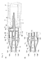
以下、本発明の吸入式デバイスの実施形態について図面を参照して説明する。図1から図8は第1の実施形態を示し、図9から図12は第2の実施形態を示し、図13から図16は第3の実施形態を示している。 Hereinafter, embodiments of the inhalation-type device of the present invention will be described with reference to the drawings. 1 to 8 show the first embodiment, FIGS. 9 to 12 show the second embodiment, and FIGS. 13 to 16 show the third embodiment.
実施形態1の説明
本実施形態の吸入式デバイスは、吸引流路1及び空気導入流路2が形成された針部(封止解除手段の一例)3と、1回投与量の医薬組成物Aが収容されて口栓(封止体の一例)4aで密封された容器4を保持するためのホルダー部5と、該ホルダー部5の容器4を収納するための収納室6と、ホルダー部5を針部3の軸線方向にガイドするためのガイド部7と、ホルダー部5をガイド部7に沿って前進及び後退させるホルダー作動部15とを備えており、これらは筒状のハウジング9に収納されている。また、ハウジング9の先部にはマウスピース10が設けられている。
Description of Embodiment 1 The inhalation-type device of this embodiment includes a needle portion (an example of a seal release means) 3 in which a suction flow path 1 and an air
医薬組成物Aは容器内に流入される空気の衝撃を受けることにより、瞬時もしくは速やかに経肺投与に適した粒子径まで微粒子化できるものであり、本実施形態では凍結乾燥型が採用されている。なお、凍結乾燥型医薬組成物の詳細については後述する。 The pharmaceutical composition A can be micronized to a particle size suitable for transpulmonary administration instantaneously or quickly by receiving the impact of air flowing into the container. In this embodiment, a freeze-dried type is adopted. Yes. The details of the freeze-dried pharmaceutical composition will be described later.
図5に示すように、ハウジング9は、ホルダー部5が後退した位置に出し入れ口9Aが形成されたハウジング本体9Bと、出し入れ口9Aを開閉する蓋9Cとを備えている。蓋9Cはハウジング本体9Bにヒンジ9Dにて連結され、また、蓋9Cには容器4の装填を確認するための窓9Eが設けられている。
As shown in FIG. 5, the
ハウジング9の壁部には外気を導入するための導入口9Fが設けられ、導入口9Fには該導入口9Fから微粒子化した医薬組成物Aが流出するのを防ぐ逆止弁9Gが装着されている。
The wall portion of the
針部3の基端部にはフランジ状の隔壁部3Aが形成され、針部3の空気導入流路2の端部は隔壁部3A内を通って該隔壁部3Aの外周壁面に開口している。また、隔壁部3Aの外周端から前方に向けて周壁部3Bが延設され、該周壁部3Bには嵌合孔3Cが形成されている。また、針部3から前方に向けて嵌合突起3Dが設けられ、吸引流路1は嵌合突起3Dを通って該嵌合突起3Dの先端に開口している。
A flange-shaped
そして、針部3の隔壁部3Aをハウジング9の先端部に嵌着することにより針部3がハウジング9に取り付けられる。なお、ハウジング9の軸線方向と針部3の軸線方向とは合致する。
Then, the
マウスピース10は、針部3の吸引流路1と連通して微粒子化した医薬組成物Aを導入するためのマウス側流路11と、該マウス側流路11と合流することなく外部空気を被験者の口腔内に導入するための補助流路12とを有する。
The
マウス側流路11はマウスピース10を貫通し、マウス側流路11の先端及び後端はマウスピース10の前面側及び後面側に開口することにより前開口部11A及び後開口部11Bが形成され、また、後開口部11Bには嵌合凹部11Cが形成されている。図3のようにマウス側流路11にはオリフィス13Aを有する仕切り部13が設けられ、オリフィス13Aの中心はマウスピース10のマウス側流路11の中心軸線上に位置している。
The
補助流路12は、図4のようにマウス側流路11の周囲に環状に形成され、補助流路12の後端はマウスピース10の後面側に開口して外気を導入するための補助空気導入口12Cが形成され、補助流路12の先部は複数の吸入枝路12Aに分岐している。これら吸入枝路12Aはマウスピース10の前面側に開口して補助開口部12Bが形成され、これら補助開口部12Bはマウス側流路11の前開口部11Aを囲繞し、患者がマウスピース10をくわえたときには、マウス側流路11の前開口部11A及び補助流路12の補助開口部12Bが患者の口腔内に位置するようになっている。
The
また、マウスピース10には後方に延びる取付片14が上下に一対形成され、各取付片14には嵌合突起14Aが形成されている。
The
そして、針部3の嵌合突起3Dをマウスピース10のマウス側流路11の後開口部11Bの嵌合凹部11Cに嵌合して吸引流路1とマウス側流路11とを連通させ、また、マウスピース10の上下一対の取付片14を針部3の周壁部3B内に嵌め込んで、針部3の周壁部3Bに形成される嵌合孔3Cに取付片14の嵌合突起14Aを嵌合することによりマウスピース10が針部3に固定されている。
Then, the
これにより、針部3の吸引流路1とマウスピース10のマウス側流路11とによって患者の口腔内に微粒子化した医薬組成物Aを吸入させるメイン流路と、補助流路12によって補助空気導入口12Cから導入される補助空気を患者の口腔内に吸入させるサブ流路との2つルートが交わらず、補助空気を直接患者の口腔内に流入することができる。
As a result, the main flow path for inhaling the finely divided pharmaceutical composition A into the patient's oral cavity by the suction flow path 1 of the
吸入式デバイスのその他の構成であるホルダー作動部15は、ホルダー部5をハウジング9の軸線方向に往復動させるための機構部15Aと、該機構部15Aを操作する操作レバーとを備えている。機構部15Aは連結体15Bを備えている。連結体15Bの一端はホルダー部5にヒンジ5Aにて連結され、連結体15Bの他端は蓋9Cにヒンジ91Aにて連結されている。蓋9Cは前記操作レバーを兼ね、蓋9Cの開閉操作によってホルダー部5をガイド部7に沿って前進及び後退させる。また、ホルダー部5には容器4をホルダー部5の底部から起こして取り出すための取り出し体16が取り付けられ、取り出し体16には容器4を起こすためのレバー17が形成されている。
The
そして、吸入式デバイスは次のようにして使用されるものである。まず、図5のように蓋9Cを起こしてハウジング9の出し入れ口9Aを開くことにより、ホルダー部5が後方に引き寄せられてハウジング9の出し入れ口9Aまで後退する。次に、容器4を口栓4aを前向きにしてホルダー部5に取り付ける。次に、図6のように蓋9Cを倒してハウジング9の出し入れ口9Aを閉じることにより、連結体15Bによってホルダー部5が針部3の方に押し込まれて容器4の口栓4aが針部3の先端に突き刺さり、針部3の吸引流路1及び空気導入流路2と容器4の内部とが連通する。
The inhalation device is used as follows. First, as shown in FIG. 5, the
次に、患者がマウスピース10をくわえて患者の吸気圧によってマウスピース10のマウス側流路11から針部3の吸引流路1を介して容器4内の空気を吸引する。このとき容器4内は負圧になって逆止弁9Gが開き、外気が針部3の空気導入流路2を通って容器4内に外気が流入する。これにより、容器4内において空気衝撃が発生して医薬組成物Aが微粒子化し、該微粒子は吸引流路1及びマウス側流路11から患者の肺器官内に送られる。それと同時に、補助空気は補助空気導入口12Cから補助流路12を通って患者の口腔に直接吸入される。このように、補助空気は吸引流路1及びマウス側流路11を流れる微粒子化した医薬組成物Aを含んだ空気と混ざることがないので、微粒子が補助空気の流れに影響されて合体・凝集することがない。なお、肺活量が低下した患者や子供の患者であっても、補助空気を吸入することにより、負担がかからずに吸入式デバイスを使用できる。
Next, the patient sucks the air in the
また、患者の吸気力不足等により医薬組成物Aの一部が微粒子の凝集塊の状態で分散した場合であっても、マウスピース10のマウス側流路11内には仕切り部13が存在するので、凝集塊はオリフィス13Aを通過する際にオリフィス13Aの周囲に位置する仕切り部13に衝突して分散されて微粒子化される。また、マウス側流路11を通過するときに生成される凝集塊も仕切り部13によって分散される。
Even when a part of the pharmaceutical composition A is dispersed in the form of agglomerates of fine particles due to a lack of inspiratory force of the patient or the like, the
また、逆止弁9Gが存在するので、患者が誤ってマウスピース10のマウス側流路11から容器4内に空気を吹き込んでも、微粒子化した医薬組成物Aが導入口9Fから外部に排出されない。
In addition, since the
そして、経肺投与が完了した後は、図7のように蓋9Cを起こしてホルダー部5をハウジング9の出し入れ口9Aまで引き寄せ、図8のようにレバー17で取り出し体16を起こして容器4をホルダー部5から取り出す。
After the completion of transpulmonary administration, the
また、本吸入式デバイスを使用しないときには、図1のようにマウスピース10はキャップ18で塞がれる。
When the inhalation device is not used, the
患者の1回の吸入の空気流量は通常5〜300L/分の範囲にある。本発明の吸入デバイスは、かかる患者の呼吸能力に応じて、容器4の容量を約5mlに、空気導入流路2の口径(直径)を約2mmに、吸引流路1の口径を約2mmに、吸入枝路12Aの口径を約1mmに設定している。
The patient's single inhalation air flow is typically in the range of 5 to 300 L / min. In the inhalation device of the present invention, the capacity of the
実施形態2の説明
本実施形態の吸入式デバイスは、図9及び図10のように2つの仕切り部13、131がマウスピース10のマウス側流路11,111に沿って適宜間隔を置いて形成されている。なお、マウスピース10以外の構成は第1実施形態と同一又は類似しており、該同一又は類似の構成については図面に同符号を付してその説明を省略する。
Description of
前側の仕切り部13には一個のオリフィス13Aが形成され、該オリフィス13Aの中心はマウスピース10のマウス側流路11の中心軸線上に位置している。また、後側の仕切り部131は図11のように複数個のオリフィス131Aがほぼ均一に配設されている。
One
マウスピース10は前後に2分割可能に構成され、前側分割体101には仕切り部13が、後側分割体102には仕切り部131がそれぞれ形成されている。
The
図12のように前分割体101は、第1の実施形態のマウスピース10と同様に、マウス側流路11と補助流路12とを有し、マウス側流路11の後開口部11Bには嵌合凹部11Cが形成され、補助流路12の内壁面には嵌合凹部101Aが形成されている。また、図11のように後分割体102はマウス側流路111を有する内管部102Aと外管部102Bとを一体化して構成されている。外管部102Bには嵌合突起102C,102Dが形成されている。
As in the
そして、後分割体102の内管102Aの先端を前分割体101の嵌合凹部11Cに挿着すると共に外管部102Bの嵌合突起102Dを前分割体101の嵌合凹部101Aに嵌合する。これにより、前後の側分割体101,102同士は連結される。また、後分割体102の外管部102Bを針部3の周壁部3B内に嵌合し、外管部102Bの嵌合突起102Cを周壁部3Bの嵌合孔3Cに嵌合すると共に内管部102Aを針部3の嵌合突起3Dに嵌合する。これによりマウスピース10をハウジング1の先に位置させる。
Then, the front end of the
本実施形態の吸入式デバイスも上述のようにして使用され、補助空気は図10の矢印のようにマウスピース10の前分割体101の補助空気導入口12Cから導入される。
The inhalation-type device of this embodiment is also used as described above, and auxiliary air is introduced from the
また、マウスピース10のマウス側流路11内の2箇所に仕切り部13,131が存在するので、仕切り部13,131による医薬組成物の微粒子の凝集塊の分散を促進することができる。なお、仕切り部を3つ以上の箇所に設けても良い。
Moreover, since the
実施形態3の説明
図13から図15のようにマウスピース10は、外殻体10Aと、仕切り部10Bを有する円筒状の内部部材10Cと、仕切り体10Dとを備えている。なお、マウスピース10以外の吸入式デバイスの構成は第1実施形態と同じであるので、その説明を省略する。
Description of
マウスピース10は、外殻体10A内に内部部材10Cを後方から嵌め込み、内部部材10C内に仕切り体10Dを後方から嵌め込むことによって組み立てられる。また、内部部材10Cの後部側の外周面には周方向に所定間隔で複数のスペーサー101Cが突設されている。外殻体10Aの後部側の内周面には周方向全長にわたって段部101Aが形成されている。そして、スペーサー101Cを外殻体10Aの段部101Aの嵌め込むことにより、外殻体10Aと内部部材10Cとの間の円筒状の隙間が形成され、該隙間は補助流路12となる。
The
補助流路12の先端部には環状の空気流出口12Dが形成されている。空気流出口12Dは、マウス側流路11の途中に位置しており、また、マウス側流路11の空気流出方向に向けて開口している。そして、補助空気導入口12Cから導入された補助空気は、スペーサー101Cの間から補助流路12内に流入し、補助流路12を通って空気流出口12Dからマウス側流路11内に環状に流入する。
An
内部部材10Cの仕切り部10B及び仕切り体10Dのそれぞれには、均一に分散する複数個のオリフィス10E,10Fが形成されている。また、内部部材10Cの仕切り部10B及び仕切り体10Dの厚さを大きくすることにより、オリフィス10E,10Fはマウス側流路11の空気流出方向に細長くなっている。また、オリフィス10E,10Fは、空気流出口12Dよりも前方に位置するものではない。
A plurality of
そして、本実施形態の吸入式デバイスは次のようにして使用されるものである。まず、上述の要領で針部3の吸引流路1及び空気導入流路2と容器4の内部とを連通させる。次に、患者がマウスピース10をくわえて吸引することにより、補助空気は、補助空気導入口12Cから補助流路12に流入し、空気流出口12Dからマウス側流路11内に層流状態で環状に流出する。一方、針部3の空気導入流路2から流入する外部空気による空気衝撃によって医薬組成物は微粉化する。医薬組成物の微粒子を含む外部空気は、吸引流路1からマウス側流路11に流れ、オリフィス10Eを通過した後は、該空気流出口12Dから流出する補助空気によって囲繞されてマウスピース10の前開口部11Aから流出する。これによって医薬組成物の微粒子を含む外部空気の流れが乱れるのを防止できて医薬組成物の微粒子の拡散が抑えられる。
また、マウスピース10は、微粒子を含む外部空気がオリフィス10Eを通過する前に、補助空気が空気流出口12Dからマウス側流路11内に流出するように設定されている。したがって、微粒子を含む外部空気を層流の補助空気によって確実に囲繞することができる。
And the inhalation type device of this embodiment is used as follows. First, the suction flow path 1 and the air
Further, the
また、微粒子を含む外部空気の流れとマウス側流路11の内周壁面との間に、補助空気の流れが介在するので、マウスピース10がプラスチック等のように静電気が発生し易い材質で形成されている場合であっても、マウス側流路11等の壁面への医薬組成物の微粒子の付着を防止できる。
Moreover, since the flow of auxiliary air is interposed between the flow of external air containing fine particles and the inner peripheral wall surface of the mouse-
図16は、マウスピース10の前側にのみオリフィス10Eを形成した吸入式デバイスを示している。
FIG. 16 shows an inhalation-type device in which an
実施態様4の説明
図17乃至図20のように吸入式デバイスは、本体100aと、マウスピース100bと、空気衝撃を受けることによって微粒子化して空気中に分散する医薬組成物Aを収納するための容器100cと、を備えている。
Description of
図18のようにマウスピース100bは円筒状に形成され、マウスピース100b内には仕切り部材100dによって仕切り部100eが形成されている。仕切り部材100dが円盤状に形成され、仕切り部材100dには複数のオリフィス100fが形成され、仕切り部材100dの外周面には切り欠き部100gが形成されている。切り欠き部100gによってマウスピース100bと仕切り部材100dとの間には、補助空気をマウスピース100b内に吸引するための補助流路100hが形成されている。補助流路100hの一端には空気導入口100iが形成され、補助流路100hの他端は空気流出口100jが形成されている。なお、実施形態3の説明で述べたように空気流出口100jを環状に形成しても良い。
As shown in FIG. 18, the
図19のように本体100aは円筒状に形成され、本体100aの端部には空気導入口100kを形成するための切り欠き部100mが形成されている。
As shown in FIG. 19, the
図20のように容器100cは円筒状に形成され、底部100pを有する。
As shown in FIG. 20, the
吸入式デバイスは、本体100aの一端にマウスピース100bを取り付けると共に本体100aの他端に容器100cを着脱自在に取り付けることにより組み立てられる。図20(a)(b)のように容器100cの深さは適宜設計変更される。
The inhalation-type device is assembled by attaching the
図17のように吸入式デバイスには、本体100aとマウスピース100bと容器100cとによって、医薬組成物Aの微粒子を含む外部空気を吸引するための、吸引流路100q及びマウスピース側の吸引流路100rが形成されている。吸引流路100qには容器100c内の空間が含まれる。
As shown in FIG. 17, the inhalation type device includes a
吸引流路100q及び吸引流路100rを合わせた容量は、患者の吸気によって空気導入口100kから流入する外部空気が、仕切り部100eよりも上流側に位置する吸引流路100q内に充満して医薬組成物Aに空気衝撃を加えることができる大きさである。前記容量としては3〜100mlを例示することができる。吸入式デバイスをシガレットとほぼ同じサイズあるいはそれよりも小さい形にまで小型化することができる。全長が80mm、外径が10mm、内径が8mmの寸法の吸入式デバイスを例示することができる。
The combined capacity of the
このように本実施形態の吸入式デバイスによれば、筒状の本体100aとマウスピース100bと医薬組成物Aの容器100cとを繋げ、外部空気の空気導入口100k及びオリフィス100fを有する仕切り部100eを設けるだけで形成されるので、シガレットとほぼ同じサイズにまで小型化することができ、また、構造が簡単になって故障し難くなる。
Thus, according to the inhalation-type device of this embodiment, the
容器100cの開口部100sをシール材で塞ぐことによって容器100c内に医薬組成物Aが封入される。吸入式デバイスを使用する時には、シール材を剥がした後に容器100cを本体100aに取り付ける。シール材はアルミニウム、プラスチックなどで形成されている。
The pharmaceutical composition A is enclosed in the
また、容器100cを取り付けた吸入式デバイスを防湿ケースや防湿袋に入れ、使用時に防湿ケースや防湿袋から吸入式デバイスを取り出すようにしても良い。このようにすれば、シール材は不要になる。
本実施形態の吸入式デバイスは次のようにして使用される。患者の吸気によって吸引流路100q内に外部空気が充満して空気の衝撃によって医薬組成物Aを微粒子化させる。医薬組成物Aの微粒子を含む外部空気は、オリフィス100fを通過した後にマウスピース100b内の吸引流路100rを通って患者の口腔内に吸引され、また、医薬組成物Aの微粒子の凝集塊を、オリフィス100fを通過することによって分散させることができる。一方、患者の吸気によって補助流路100hからマウスピース100b内に補助空気が流入して患者の負担の軽減が図れる。
Alternatively, the inhalation device with the
The inhalation type device of this embodiment is used as follows. External air is filled in the
図21から図23はその他の実施態様例を示す。図21に示す吸入式デバイスでは、操作体19が矢印のようにハウジング9の周方向に正逆回転可能となるように配設されている。図示しないホルダー作動部の機構部は、螺旋溝とこれに係合するフォロワーを備え、操作体19の正逆回転運動によりホルダー部5を針部3の軸線方向への直線運動(往復運動)に変換させる。操作体19の回転角度はほぼ180度に設定されている。また、図18及び図19に示す吸入式デバイスは、ハウジング9に環状の操作体19が回転自在に取り付けられている。図示しないホルダー作動部の機構部は、送りねじを備え、操作体19の回転運動によりホルダー部5を針部3の軸線方向への直線運動に変換させる。ホルダー部5はハウジング9の後部から引き出し自在となっている。なお、マウスピース10などのその他の構成は第1又は第2の実施形態と同じである。
21 to 23 show other embodiments. In the inhalation type device shown in FIG. 21, the operating
凍結乾燥型医薬組成物の説明
凍結乾燥型医薬組成物は、単回投与の有効量の薬物を含む溶液を容器に液充填し、そのまま凍結乾燥することによって非粉末の乾燥状態に調製されてなるものである。かかる非粉末状態の凍結乾燥型医薬組成物は、用時溶解型の注射剤等の凍結乾燥製剤(凍結乾燥型医薬組成物)の製造に一般的に用いられる製造方法を用いて製造されるが、調製される凍結乾燥型医薬組成物の崩壊指数が0.015以上となるように適切な組成(有効成分、並びに該有効成分と併用する担体の種類及びその量)を選択することにより、容器内で空気の衝撃を受けて経肺投与に適した粒子径まで微粒子化することができる。
Description of freeze-dried pharmaceutical composition A freeze-dried pharmaceutical composition is prepared in a non-powder dry state by filling a container with a solution containing an effective dose of a single dose into a container and freeze-drying the solution as it is. Is. Such a lyophilized pharmaceutical composition in a non-powder state is produced using a production method generally used for the production of lyophilized preparations (lyophilized pharmaceutical compositions) such as injectable preparations for use. By selecting an appropriate composition (the active ingredient and the type and amount of the carrier used in combination with the active ingredient) such that the disintegration index of the lyophilized pharmaceutical composition to be prepared is 0.015 or more, It can be micronized to a particle size suitable for transpulmonary administration under the impact of air.
なお、本発明でいう崩壊指数は、凍結乾燥型医薬組成物について下記の方法に従って測定することによって得ることができる当該凍結乾燥型医薬組成物固有の値である。
<崩壊指数>
胴径φ18mmあるいは胴径φ23mmの容器に、対象とする凍結乾燥型医薬組成物を構成する目的の成分を含有する溶液を0.2〜0.5mlの範囲で液充填して、それを凍結乾燥する。次いで得られた非粉末状の凍結乾燥型医薬組成物に,n-ヘキサンを容器の壁を通じて静かに1.0ml滴下する。これを3000rpmで約10秒間攪拌させた混合液を光路長1mm,光路幅10mmのUVセルに投入し,速やかに分光光度計を用いて測定波長500nmで濁度を測定する。得られた濁度を凍結乾燥型医薬組成物を構成する成分の総量(重量)で割り、得られた値を崩壊指数と定義する。
ここで本発明の凍結乾燥型医薬組成物が備える崩壊指数の下限値としては、上記の0.015、好ましくは0.02、より好ましくは0.03、さらに好ましくは0.04、更により好ましくは0.05、特に好ましくは0.1を挙げることができる。また本発明の凍結乾燥型医薬組成物が備える崩壊指数の上限値としては特に制限されないが、1.5、好ましくは1、より好ましくは0.9、さらに好ましくは0.8、更により好ましくは0.7を挙げることができる。好適には本発明の凍結乾燥型医薬組成物は、0.015以上であることを限度として、上記から任意に選択される下限値と上限値から構成される範囲内にある崩壊指数を有することが望ましい。例えば、崩壊指数の範囲として具体的には0.015〜1.5、0.02〜1、0.03〜0.9、0.04〜0.8、0.05〜0.7、0.1〜0.7を例示することができる。
また、本発明の凍結乾燥型医薬組成物は、凍結乾燥によって非粉末のケーキ状の形態に調製されることが望ましい。本発明において非粉末状の凍結乾燥型医薬組成物とは、溶液を凍結乾燥して得られる乾燥固体であり、通常、凍結乾燥ケーキと呼ばれるものを意味する。但し、凍結乾燥工程あるいはその後のハンドリングでケーキにひびが入ったり、数個の大きな塊になったり、一部が破損して粉状になったものも、本発明の効果を損なわないことを限度として本発明が対象とする非粉末状の凍結乾燥型医薬組成物に包含される。
In addition, the disintegration index as used in the field of this invention is a value intrinsic | native to the said freeze-drying type pharmaceutical composition which can be obtained by measuring according to the following method about a freeze-drying type pharmaceutical composition.
<Collapse index>
A container having a trunk diameter of φ18 mm or a trunk diameter of φ23 mm is filled with a solution containing a target component constituting a target freeze-dried pharmaceutical composition in a range of 0.2 to 0.5 ml, and then freeze-dried. Next, 1.0 ml of n-hexane is gently added dropwise to the resulting non-powdered lyophilized pharmaceutical composition through the wall of the container. The mixture is stirred at 3000 rpm for about 10 seconds, put into a UV cell with an optical path length of 1 mm and an optical path width of 10 mm, and turbidity is measured quickly using a spectrophotometer at a measurement wavelength of 500 nm. The obtained turbidity is divided by the total amount (weight) of the components constituting the freeze-dried pharmaceutical composition, and the obtained value is defined as the disintegration index.
Here, the lower limit value of the disintegration index of the freeze-dried pharmaceutical composition of the present invention is 0.015, preferably 0.02, more preferably 0.03, still more preferably 0.04, and still more preferably. May be 0.05, particularly preferably 0.1. The upper limit of the disintegration index provided in the freeze-dried pharmaceutical composition of the present invention is not particularly limited, but is preferably 1.5, preferably 1, more preferably 0.9, still more preferably 0.8, and still more preferably 0.7 can be mentioned. Preferably, the freeze-dried pharmaceutical composition of the present invention has a disintegration index within a range composed of a lower limit value and an upper limit value arbitrarily selected from the above, up to 0.015 or more. Is desirable. For example, the range of the decay index is specifically 0.015-1.5, 0.02-1, 0.03-0.9, 0.04-0.8, 0.05-0.7, 0 .1 to 0.7 can be exemplified.
The lyophilized pharmaceutical composition of the present invention is preferably prepared in a non-powder cake form by lyophilization. In the present invention, the non-powder lyophilized pharmaceutical composition is a dry solid obtained by lyophilizing a solution, and usually means a lyophilized cake. However, the cake is cracked in the freeze-drying process or the subsequent handling, or is broken into several large lumps or partly broken into powder, so that the effect of the present invention is not impaired. As a non-powder lyophilized pharmaceutical composition to which the present invention is directed.
本発明の凍結乾燥型医薬組成物は、前述するように、0.015以上の崩壊指数と、非粉末のケーキ状の形態を備えており、上記崩壊指数で表現される該凍結乾燥型医薬組成物の固有の性質に基づいて、少なくとも1m/secの空気速度及び少なくとも17ml/secの空気流量を有する空気の衝撃を受けることによって、平均粒子径が10ミクロン以下または有効粒子割合が10%以上の微粒子になることを特徴とするものである。 As described above, the lyophilized pharmaceutical composition of the present invention has a disintegration index of 0.015 or more and a non-powder cake-like form, and the lyophilized pharmaceutical composition represented by the disintegration index. Based on the inherent properties of the object, the average particle size is 10 microns or less or the effective particle ratio is 10% or more by receiving the impact of air having an air velocity of at least 1 m / sec and an air flow rate of at least 17 ml / sec. It is characterized by becoming fine particles.
好ましい凍結乾燥型医薬組成物としては、上記空気衝撃を受けることによって、平均粒子径が10ミクロン以下、好ましくは5ミクロン以下、または有効粒子割合が10%以上、好ましくは20%以上、より好ましくは25%以上、さらに好ましくは30%以上、特に好ましくは35%以上の微粒子になるものを挙げることができる。 As a preferable freeze-dried pharmaceutical composition, the average particle size is 10 microns or less, preferably 5 microns or less, or the effective particle ratio is 10% or more, preferably 20% or more, more preferably, by receiving the air impact. Examples of the fine particles include 25% or more, more preferably 30% or more, and particularly preferably 35% or more.
なお、凍結乾燥型医薬組成物に与える空気衝撃は、前述するように1m/sec以上の空気速度及び17ml/sec以上の空気流量を有する空気によって生じる衝撃であれば特に制限されない。具体的には、上記の空気衝撃としては、1m/sec以上、好ましくは2m/sec以上、より好ましくは5m/sec以上、よりさらに好ましくは10m/sec以上の空気速度によって生じる衝撃を例示することができる。ここで空気速度の上限としては、特に制限されないが、通常300m/sec、好ましくは250m/sec、より好ましくは200m/sec、よりさらに好ましくは150m/secを挙げることができる。なお、空気速度は、上記から任意に選択される下限と上限から構成される範囲内にあれば特に制限されないが、具体的には1〜300m/sec、1〜250m/sec、2〜250m/sec、5〜250m/sec、5〜200m/sec、10〜200m/sec、10〜150m/secの範囲を挙げることができる。 The air impact applied to the freeze-dried pharmaceutical composition is not particularly limited as long as it is an impact caused by air having an air velocity of 1 m / sec or more and an air flow rate of 17 ml / sec or more as described above. Specifically, the above-mentioned air impact is exemplified by an impact caused by an air velocity of 1 m / sec or more, preferably 2 m / sec or more, more preferably 5 m / sec or more, and even more preferably 10 m / sec or more. Can do. Here, the upper limit of the air velocity is not particularly limited, but is usually 300 m / sec, preferably 250 m / sec, more preferably 200 m / sec, and still more preferably 150 m / sec. The air speed is not particularly limited as long as it is within a range constituted by a lower limit and an upper limit arbitrarily selected from the above, but specifically, 1 to 300 m / sec, 1 to 250 m / sec, 2 to 250 m / The range of sec, 5-250 m / sec, 5-200 m / sec, 10-200 m / sec, 10-150 m / sec can be mentioned.
また、上記の空気衝撃としては、通常17ml/sec以上、好ましくは20ml/sec以上、より好ましくは25ml/sec以上の空気流量によって生じる衝撃を例示することができる。ここで空気流量の上限は、特に制限されないが、900L/min、好ましくは15L/sec、より好ましくは10L/sec、さらに好ましくは5L/sec、さらにより好ましくは4L/sec、特に好ましくは3L/secである。具体的には、空気流量は上記から任意に選択される下限と上限から構成される範囲内にあればよく、特に制限されないが、かかる範囲としては例えば17ml/sec〜15L/sec、20ml/sec〜10L/sec、20ml/sec〜5L/sec、20ml/sec〜4L/sec、20ml/sec〜3L/sec、25ml/sec〜3L/secを挙げることができる。 Moreover, as said air impact, the impact produced by the air flow rate of 17 ml / sec or more normally, Preferably 20 ml / sec or more, More preferably, 25 ml / sec or more can be illustrated. Here, the upper limit of the air flow rate is not particularly limited, but is 900 L / min, preferably 15 L / sec, more preferably 10 L / sec, further preferably 5 L / sec, even more preferably 4 L / sec, particularly preferably 3 L / sec. sec. Specifically, the air flow rate is not particularly limited as long as it is within a range composed of a lower limit and an upper limit arbitrarily selected from the above, but such ranges include, for example, 17 ml / sec to 15 L / sec, 20 ml / sec. -10 L / sec, 20 ml / sec to 5 L / sec, 20 ml / sec to 4 L / sec, 20 ml / sec to 3 L / sec, 25 ml / sec to 3 L / sec.
本発明に係る経肺投与用の吸入式デバイスは、以上に説明したとおり構成されているので、その効果は以下の通り多大である。 Since the inhalation-type device for pulmonary administration according to the present invention is configured as described above, the effect is great as follows.
以上から明らかなように、本発明の吸入式デバイスによれば、前記マウスピースは、前記吸引流路と連通するマウス側流路と、前記吸引流路及び前記マウス側流路と合流することなく外部空気を直接吸引するための補助流路とを有し、被験者の吸気圧により外部空気を前記補助流路に直接導入するように構成したので、補助空気は微粒子化した医薬組成物を含んだ空気と衝突することがなく、微粒子が補助空気の流れに影響されて合体・凝集するのを防止できる。また、医薬組成物を含まない補助空気がストレートに吸引されることにより、空気流を更に増強することができ、生成された微粒子を効率良く肺に送り込むことができる。 As is apparent from the above, according to the inhalation-type device of the present invention, the mouthpiece does not merge with the mouth side channel communicating with the suction channel, the suction channel and the mouth side channel. And an auxiliary flow path for directly sucking the external air, and the external air is directly introduced into the auxiliary flow path by the subject's inspiratory pressure, so that the auxiliary air contains a micronized pharmaceutical composition Without colliding with air, it is possible to prevent the fine particles from being coalesced and aggregated by being influenced by the flow of auxiliary air. Further, since the auxiliary air not containing the pharmaceutical composition is sucked straight, the air flow can be further enhanced, and the generated fine particles can be efficiently sent to the lungs.
また、本発明の吸入式デバイスによれば、前記マウス側流路及び前記吸引流路の少なくとも一方に、段部を経て流路径を小さくするためのオリフィスを有する仕切り部を形成したので、マウスピースのマウス側流路を通過する医薬組成物の微粒子の凝集塊を分散させることができる。 Further, according to the inhalation-type device of the present invention, since the partition part having an orifice for reducing the diameter of the channel through the step part is formed in at least one of the mouth side channel and the suction channel, the mouthpiece The agglomerates of fine particles of the pharmaceutical composition that pass through the mouse side channel can be dispersed.
また、前記オリフィスを有する仕切り部を適宜間隔を置いて複数形成すれば、医薬組成物の凝集塊の分散を更に促進できる。 Further, if a plurality of partition portions having the orifice are formed at appropriate intervals, the dispersion of the aggregate of the pharmaceutical composition can be further promoted.
また、従来技術にみられる補助空気の流れによる微粒子の合体・凝集を防止できると共にマウスピースのマウス側流路を通過する医薬組成物の微粒子の凝集塊を分散できるので、医薬組成物の微粒子の凝集塊が被験者の口腔内に入るのを防止できる。 In addition, it is possible to prevent the coalescence / aggregation of fine particles due to the flow of auxiliary air as seen in the prior art and to disperse the aggregates of the fine particles of the pharmaceutical composition passing through the mouth side channel of the mouthpiece. Aggregates can be prevented from entering the subject's mouth.
また、本発明の吸入式デバイスによれば、空気衝撃で微粒子化した前記医薬組成物は、補助空気に囲繞された状態で前記マウス側流路内を流れるように構成したので、乱流による医薬組成物の微粒子の拡散を抑えることができ、医薬組成物の微粒子はマウス側流路内を速やかに流れて肺内に至ることができ、のどへの医薬組成物の微粒子の付着を防止できる。また、静電気によるマウスピースへの医薬組成物の微粒子の付着を防止できる。
また、微粒子化した前記医薬組成物を含む外部空気は、前記オリフィスを通過した後に、補助空気によって囲繞すれば、補助空気の流れがオリフィスによって乱されることがなくなる。
In addition, according to the inhalation-type device of the present invention, the pharmaceutical composition that has been microparticulated by air impact is configured to flow in the mouse-side channel in a state surrounded by auxiliary air. The diffusion of the fine particles of the composition can be suppressed, and the fine particles of the pharmaceutical composition can quickly flow in the mouse side flow path and reach the lungs, thereby preventing the fine particles of the pharmaceutical composition from adhering to the throat. Moreover, adhesion of the fine particles of the pharmaceutical composition to the mouthpiece due to static electricity can be prevented.
Further, if the external air containing the micronized pharmaceutical composition passes through the orifice and is surrounded by the auxiliary air, the flow of the auxiliary air is not disturbed by the orifice.
また、前記オリフィスの流路長を前記マウス側流路の空気流出方向に長くなるように形成すれば、前記医薬組成物を含む前記外部空気の乱流が前記オリフィス内で加速されて層流状態になり、前記医薬組成物を含む前記外部空気が補助空気によって囲繞され易くなる。 Further, if the flow path length of the orifice is formed so as to be longer in the air outflow direction of the mouse side flow path, the turbulent flow of the external air containing the pharmaceutical composition is accelerated in the orifice and is in a laminar flow state. Thus, the external air containing the pharmaceutical composition is easily surrounded by auxiliary air.
また、微粒子化した凍結乾燥型医薬組成物を含んだ空気と補助空気とが混ざることがなく、仕切り部によって医薬組成物の微粒子の凝集塊を分散させることができる。 Further, the air containing the lyophilized pharmaceutical composition and the auxiliary air are not mixed, and the aggregate of fine particles of the pharmaceutical composition can be dispersed by the partition part.
また、被験者が空気を吸引するのではなく、誤って息を吐いた場合でも逆支弁を装備すれば、前記微粒子を前記空気導入流路から外部に流出するのを防ぐことができる。 In addition, even if the subject does not inhale air but exhales by mistake, if the reverse support valve is equipped, the fine particles can be prevented from flowing out from the air introduction channel.
A 医薬組成物
1 吸引流路
2 空気導入流路
3 針部(封止解除手段)
6 収納室
9 ハウジング
9G 逆止弁
10 マウスピース
11 マウスピースのマウス側流路
12 マウスピースの補助流路
13 仕切り部
13A オリフィス
A Pharmaceutical composition 1
6
Claims (11)
前記医薬組成物に空気衝撃を与える外部空気を前記収納室内に導入して前記医薬組成物に向けて放射するための空気導入流路と、
微粒子化した医薬組成物を吸引するために吸引口が前記収納室に臨むように設けられた吸引流路と、
前記収納室、前記空気導入流路及び前記吸引流路を収めるハウジングと、
前記ハウジングの一端部に設けられるマウスピースと、を備え、
前記マウスピースは、前記吸引流路と連通するマウス側流路と、前記吸引流路及び前記マウス側流路に合流することなく外部空気を直接吸引するための補助流路とを有し、
被験者が吸気したときには、その吸気圧により前記収納室内に流入した外部空気により前記医薬組成物に空気衝撃が与えられ、微粒子化した前記医薬組成物が前記マウス側流路に導入され、同時に、前記吸気圧により外部空気が前記補助流路に直接導入されるように構成したことを特徴とする経肺投与用の吸入式デバイス。 A storage chamber for storing a pharmaceutical composition that is microparticulated by air shock and dispersed in the air;
An air introduction flow path for introducing external air that gives an air shock to the pharmaceutical composition into the storage chamber and radiating the air toward the pharmaceutical composition;
A suction flow path provided so that a suction port faces the storage chamber in order to suck the finely divided pharmaceutical composition;
A housing for housing the storage chamber, the air introduction channel, and the suction channel;
A mouthpiece provided at one end of the housing,
The mouthpiece includes a mouth side channel communicating with the suction channel, and an auxiliary channel for directly sucking external air without joining the suction channel and the mouse side channel,
When the subject inhales, the air shock is given to the pharmaceutical composition by the external air flowing into the storage chamber due to the intake pressure, and the micronized pharmaceutical composition is introduced into the mouse-side flow path, and at the same time, An inhalation-type device for transpulmonary administration, wherein external air is directly introduced into the auxiliary flow path by inhalation pressure.
前記医薬組成物に空気衝撃を与える外部空気を前記収納室内に導入して前記医薬組成物に向けて放射するための空気導入流路と、
微粒子化した医薬組成物を吸引するために吸引口が前記収納室に臨むように設けられた吸引流路と、
前記収納室、前記空気導入流路及び前記吸引流路を収めるハウジングと、
前記ハウジングの一端部に設けられるマウスピースと、を備え、
前記マウスピースは、前記吸引流路と連通するマウス側流路を有し、該マウス側流路及び前記吸引流路の少なくとも一方に、段部を経て流路径を小さくするためのオリフィスを有する仕切り部を形成し、
被験者が吸気したときには、その吸気圧により前記収納室内に流入する外部空気により前記医薬組成物に空気衝撃が与えられ、微粒子化した前記医薬組成物が前記吸引流路及び前記マウス側流路に導入されると共に前記オリフィスを通過するように構成したことを特徴とする経肺投与用の吸入式デバイス。 A storage chamber for storing a pharmaceutical composition that is microparticulated by air shock and dispersed in the air;
An air introduction flow path for introducing external air that gives an air shock to the pharmaceutical composition into the storage chamber and radiating the air toward the pharmaceutical composition;
A suction flow path provided so that a suction port faces the storage chamber in order to suck the finely divided pharmaceutical composition;
A housing for housing the storage chamber, the air introduction channel, and the suction channel;
A mouthpiece provided at one end of the housing,
The mouthpiece has a mouth side channel communicating with the suction channel, and at least one of the mouse side channel and the suction channel has a partition having an orifice for reducing a channel diameter through a step portion. Forming part,
When the subject inhales, an air impact is given to the pharmaceutical composition by the external air flowing into the storage chamber by the intake pressure, and the finely divided pharmaceutical composition is introduced into the suction channel and the mouse side channel. And an inhalation device for transpulmonary administration, wherein the inhalation device is configured to pass through the orifice.
微粒子化した前記医薬組成物が前記吸引流路及び前記マウス側流路に導入されると同時に、前記吸気圧により外部空気が前記補助流路に直接導入されるように構成したことを特徴とする請求項2又は3に記載の経肺投与用の吸入式デバイス。 The mouthpiece has an auxiliary flow path for directly sucking outside air without joining the suction flow path and the mouse side flow path,
The micronized pharmaceutical composition is introduced into the suction channel and the mouse side channel, and at the same time, external air is directly introduced into the auxiliary channel by the intake pressure. The inhalation-type device for transpulmonary administration according to claim 2 or 3.
前記医薬組成物に空気衝撃を与える外部空気を前記収納室内に導入して前記医薬組成物に向けて放射するための空気導入流路と、
微粒子化した医薬組成物を吸引するための吸引流路と、
前記収納室、前記空気導入流路及び前記吸引流路を収めるハウジングと、
前記ハウジングの一端部に設けられるマウスピースと、を備え、
前記マウスピースは、
前記吸引流路と連通するマウス側流路と、
前記医薬組成物への空気衝撃に寄与しない外部空気を、前記収容室を経由せずに吸引し、且つ、前記マウス側流路内に開口する空気流出口を通じて前記マウス側流路内に流入させるための補助流路を備え、
前記空気流出口は、前記マウス側流路の空気流出方向に向けて開口すると共に前記マウス側流路の内周壁面に沿って環状に形成され、
被験者が吸気したときには、その吸気圧により前記収納室内に流入する外部空気による空気衝撃で微粒子化した前記医薬組成物は、前記吸引流路を通じて前記マウス側流路内に導入され、且つ、環状の前記空気流出口から前記マウス側流路内に流出する外部空気に囲繞された状態で前記マウス側流路内を流れるように構成したことを特徴とする経肺投与用の吸入式デバイス。 A storage chamber for storing a pharmaceutical composition that is microparticulated by air shock and dispersed in the air;
An air introduction flow path for introducing external air that gives an air shock to the pharmaceutical composition into the storage chamber and radiating the air toward the pharmaceutical composition;
A suction channel for aspirating the micronized pharmaceutical composition;
A housing for housing the storage chamber, the air introduction channel, and the suction channel;
A mouthpiece provided at one end of the housing,
The mouthpiece is
A mouse side channel communicating with the suction channel;
External air that does not contribute to the air impact on the pharmaceutical composition is sucked without passing through the storage chamber, and is allowed to flow into the mouse-side channel through an air outlet opening in the mouse-side channel. An auxiliary flow path for
The air outlet is formed in an annular shape along the inner peripheral wall surface of the mouse-side flow channel while opening in the air outflow direction of the mouse-side flow channel.
When the subject inhales, the pharmaceutical composition that has been microparticulated by air impact by external air flowing into the storage chamber due to the inspiratory pressure is introduced into the mouse-side channel through the suction channel, and is annular. An inhalation device for transpulmonary administration, wherein the inhalation device is configured to flow in the mouse-side flow channel in a state surrounded by external air flowing out from the air outflow port into the mouse-side flow channel.
微粒子化した前記医薬組成物を含む外部空気は、前記オリフィスを通過した後に、環状の前記空気流出口から前記マウス側流路内に流出する外部空気によって囲繞されるように構成したことを特徴とする請求項5に記載の経肺投与用の吸入式デバイス。 Forming a partition having an orifice for reducing the channel diameter in the mouse side channel;
The external air containing the micronized pharmaceutical composition is configured to be surrounded by external air that flows out from the annular air outlet into the mouse channel after passing through the orifice. An inhalation device for transpulmonary administration according to claim 5.
前記封止体による封止を解除するための封止解除手段と、を備え、
前記封止解除手段によって前記容器の封止状態を解除して前記収納室と前記容器内とを連通させ、
前記吸気圧により前記容器内の前記医薬組成物に空気衝撃を与えるように構成したことを特徴とする請求項1から7のいずれかに記載の経肺投与用の吸入式デバイス。 The storage chamber for storing a non-powder cake-like lyophilized pharmaceutical composition in which fine particles are dispersed in the air by receiving an air impact, and storing a container sealed with a sealing body;
Sealing release means for releasing the sealing by the sealing body,
Release the sealed state of the container by the sealing release means to communicate the storage chamber and the inside of the container,
The inhalation-type device for transpulmonary administration according to any one of claims 1 to 7, wherein an air shock is given to the pharmaceutical composition in the container by the inspiratory pressure.
前記本体の一端に設けられるマウスピースと、
前記本体の他端に設けられ、空気衝撃を受けることによって微粒子化して空気中に分散する医薬組成物を収納するための容器と、
前記本体と前記マウスピースと前記容器とで形成され、前記医薬組成物の微粒子を含む外部空気を前記容器側から前記マウスピース側に向けて流すための吸引流路と、
前記吸引流路内に外部空気を導入するための空気導入口と、
前記吸引流路の流路径を小さくするためのオリフィスを有し、前記空気導入口よりも下流側に位置し、前記吸引流路を仕切るための仕切り部と、を備え、
前記吸引流路は、被験者の吸気によって前記空気導入口から前記仕切り部よりも上流側に位置する前記吸引流路内に流入する外部空気によって前記医薬組成物に空気衝撃を加えることができる容量であることを特徴とする吸入式デバイス。 A tubular body,
A mouthpiece provided at one end of the body;
A container for storing a pharmaceutical composition which is provided at the other end of the main body and is microparticulated by air impact and dispersed in the air;
A suction channel formed by the main body, the mouthpiece, and the container for flowing external air containing fine particles of the pharmaceutical composition from the container side toward the mouthpiece side;
An air inlet for introducing external air into the suction channel;
An orifice for reducing the flow path diameter of the suction flow path, located downstream from the air inlet, and a partition for partitioning the suction flow path,
The suction channel has a capacity capable of applying an air shock to the pharmaceutical composition by external air flowing into the suction channel located upstream of the partition portion from the air introduction port by inhalation of a subject. An inhalation device characterized by being.
前記空気流出口は、該空気流出口から流入する外部空気が前記オリフィスを通過することなく被験者の口腔内に吸引されるような位置に設けられたことを特徴とする請求項10に記載の吸入式デバイス。 An air outlet opening in the suction channel, and an auxiliary channel for injecting external air into the suction channel through the air outlet by inhalation of a subject,
The inhalation according to claim 10, wherein the air outlet is provided at a position such that external air flowing in from the air outlet is sucked into the oral cavity of the subject without passing through the orifice. Expression device.
Applications Claiming Priority (2)
| Application Number | Priority Date | Filing Date | Title |
|---|---|---|---|
| JP2002362754 | 2002-12-13 | ||
| PCT/JP2003/015943 WO2004054647A1 (en) | 2002-12-13 | 2003-12-12 | Inhalation device for transpulmonary administration |
Publications (2)
| Publication Number | Publication Date |
|---|---|
| JP2006509582A true JP2006509582A (en) | 2006-03-23 |
| JP4562528B2 JP4562528B2 (en) | 2010-10-13 |
Family
ID=32588170
Family Applications (1)
| Application Number | Title | Priority Date | Filing Date |
|---|---|---|---|
| JP2004560628A Expired - Fee Related JP4562528B2 (en) | 2002-12-13 | 2003-12-12 | Inhalation device for pulmonary administration |
Country Status (22)
| Country | Link |
|---|---|
| US (1) | US7708014B2 (en) |
| EP (1) | EP1572273A1 (en) |
| JP (1) | JP4562528B2 (en) |
| KR (1) | KR101024953B1 (en) |
| CN (1) | CN100551457C (en) |
| AR (1) | AR042452A1 (en) |
| AU (1) | AU2003285770B2 (en) |
| BR (1) | BR0316603B1 (en) |
| CA (1) | CA2507794C (en) |
| EA (1) | EA007730B1 (en) |
| EG (1) | EG23792A (en) |
| HK (1) | HK1082438A1 (en) |
| HR (1) | HRP20050638A2 (en) |
| IL (1) | IL168909A (en) |
| MX (1) | MXPA05006321A (en) |
| MY (1) | MY146484A (en) |
| NO (1) | NO335969B1 (en) |
| NZ (1) | NZ540936A (en) |
| PL (1) | PL208288B1 (en) |
| TW (1) | TWI313181B (en) |
| UA (1) | UA84412C2 (en) |
| WO (1) | WO2004054647A1 (en) |
Cited By (3)
| Publication number | Priority date | Publication date | Assignee | Title |
|---|---|---|---|---|
| JP2012205858A (en) * | 2011-03-30 | 2012-10-25 | Kobayashi Pharmaceutical Co Ltd | Powder inhalation instrument |
| JP2014073395A (en) * | 2008-06-13 | 2014-04-24 | Mannkind Corp | Dry powder inhaler and system for drug delivery |
| JP2015027543A (en) * | 2009-03-04 | 2015-02-12 | マンカインド コーポレイション | Improved dry powder drug delivery system |
Families Citing this family (49)
| Publication number | Priority date | Publication date | Assignee | Title |
|---|---|---|---|---|
| US9006175B2 (en) | 1999-06-29 | 2015-04-14 | Mannkind Corporation | Potentiation of glucose elimination |
| EG24184A (en) * | 2001-06-15 | 2008-10-08 | Otsuka Pharma Co Ltd | Dry powder inhalation system for transpulmonary |
| CA2479751C (en) | 2002-03-20 | 2008-06-03 | Trent Poole | Inhalation apparatus |
| ES2385934T3 (en) | 2004-08-20 | 2012-08-03 | Mannkind Corporation | CATALYSIS OF THE SYNTHESIS OF DICETOPIPERAZINA. |
| KR101644250B1 (en) | 2004-08-23 | 2016-07-29 | 맨카인드 코포레이션 | Diketopiperazine salts, diketomorpholine salts or diketodioxane salts for drug delivery |
| US8763605B2 (en) | 2005-07-20 | 2014-07-01 | Manta Devices, Llc | Inhalation device |
| DK1928423T3 (en) | 2005-09-14 | 2016-02-29 | Mannkind Corp | A method for drug formulation based on increasing the affinity of the active substances to the crystalline microparticle surfaces |
| US8039431B2 (en) | 2006-02-22 | 2011-10-18 | Mannkind Corporation | Method for improving the pharmaceutic properties of microparticles comprising diketopiperazine and an active agent |
| KR101399480B1 (en) * | 2006-06-16 | 2014-05-28 | 씨아이피엘에이 엘티디. | Improved dry powder inhaler |
| WO2008051471A2 (en) * | 2006-10-19 | 2008-05-02 | Haroutunian Greg G | Flow modification device |
| US9155849B2 (en) | 2006-10-19 | 2015-10-13 | G Greg Haroutunian | Flow modification device |
| US11224704B2 (en) | 2007-07-06 | 2022-01-18 | Manta Devices, Llc | Dose delivery device for inhalation |
| JP5528336B2 (en) | 2007-07-06 | 2014-06-25 | マンタ デバイシス,エルエルシー | Delivery device and related method |
| EP2534957B1 (en) | 2007-12-14 | 2015-05-27 | AeroDesigns, Inc | Delivering aerosolizable products |
| AU2014200952B2 (en) * | 2008-06-13 | 2014-12-11 | Mannkind Corporation | A dry powder inhaler and system for drug delivery |
| US8485180B2 (en) | 2008-06-13 | 2013-07-16 | Mannkind Corporation | Dry powder drug delivery system |
| AU2015275293B2 (en) * | 2008-06-13 | 2018-06-07 | Mannkind Corporation | A dry powder inhaler and system for drug delivery |
| US9364619B2 (en) | 2008-06-20 | 2016-06-14 | Mannkind Corporation | Interactive apparatus and method for real-time profiling of inhalation efforts |
| TWI532497B (en) | 2008-08-11 | 2016-05-11 | 曼凱公司 | Use of ultrarapid acting insulin |
| US8314106B2 (en) | 2008-12-29 | 2012-11-20 | Mannkind Corporation | Substituted diketopiperazine analogs for use as drug delivery agents |
| JP5667095B2 (en) | 2009-03-11 | 2015-02-12 | マンカインド コーポレイション | Apparatus, system and method for measuring inhaler resistance |
| SI3210644T1 (en) | 2009-05-27 | 2019-03-29 | Ino Therapeutics Llc | Devices for engaging indexed valve and pressurized canister assembly with collar |
| CA2764505C (en) | 2009-06-12 | 2018-09-25 | Mannkind Corporation | Diketopiperazine microparticles with defined specific surface areas |
| WO2011056889A1 (en) | 2009-11-03 | 2011-05-12 | Mannkind Corporation | An apparatus and method for simulating inhalation efforts |
| GB0919465D0 (en) | 2009-11-06 | 2009-12-23 | Norton Healthcare Ltd | Airflow adaptor for a breath-actuated dry powder inhaler |
| RU2571331C1 (en) | 2010-06-21 | 2015-12-20 | Маннкайнд Корпорейшн | Systems and methods for dry powder drug delivery |
| CN101856531A (en) * | 2010-06-22 | 2010-10-13 | 于清 | High-efficiency dry powder inhaler for medicament delivery and medicament delivery method thereof |
| CN105667994B (en) | 2011-04-01 | 2018-04-06 | 曼金德公司 | Blister package for pharmaceutical kit |
| WO2012174472A1 (en) | 2011-06-17 | 2012-12-20 | Mannkind Corporation | High capacity diketopiperazine microparticles |
| ES2877100T3 (en) * | 2011-07-13 | 2021-11-16 | Pharmaxis Ltd | Provisioning Device Enhancements |
| CA2852536A1 (en) | 2011-10-24 | 2013-05-02 | Mannkind Corporation | Methods and compositions for treating pain |
| US9326547B2 (en) | 2012-01-31 | 2016-05-03 | Altria Client Services Llc | Electronic vaping article |
| US9802012B2 (en) | 2012-07-12 | 2017-10-31 | Mannkind Corporation | Dry powder drug delivery system and methods |
| US10159644B2 (en) | 2012-10-26 | 2018-12-25 | Mannkind Corporation | Inhalable vaccine compositions and methods |
| ES2754388T3 (en) | 2013-03-15 | 2020-04-17 | Mannkind Corp | Compositions and methods of microcrystalline dicetopiperazine |
| WO2015006639A1 (en) * | 2013-07-12 | 2015-01-15 | SILVA, John, H. | Mouthpiece for inhalers |
| EP3021919B1 (en) * | 2013-07-16 | 2017-10-04 | Emphasys Importadora, Exportadora E Distribuidora De Embalagens Ltda. | Powder inhaler |
| US9925144B2 (en) | 2013-07-18 | 2018-03-27 | Mannkind Corporation | Heat-stable dry powder pharmaceutical compositions and methods |
| EP3030294B1 (en) | 2013-08-05 | 2020-10-07 | MannKind Corporation | Insufflation apparatus |
| US10307464B2 (en) | 2014-03-28 | 2019-06-04 | Mannkind Corporation | Use of ultrarapid acting insulin |
| WO2015168572A2 (en) | 2014-05-02 | 2015-11-05 | Manta Devices, Llc | Delivery device and related methods |
| USD748242S1 (en) | 2014-07-11 | 2016-01-26 | H. Stuart Campbell | Inhaler mouthpiece |
| US10561806B2 (en) | 2014-10-02 | 2020-02-18 | Mannkind Corporation | Mouthpiece cover for an inhaler |
| CN205322939U (en) * | 2015-10-27 | 2016-06-22 | 深圳市杰仕博科技有限公司 | Thermal -insulated suction nozzle |
| IL260823B1 (en) * | 2016-01-29 | 2024-04-01 | Mannkind Corp | Dry powder inhaler |
| CN109718431B (en) * | 2017-10-31 | 2023-11-28 | 正大天晴药业集团股份有限公司 | Medical vaporizer with improved internal air flow |
| CN108741239B (en) * | 2018-09-17 | 2021-01-12 | 杭州清大科瑞生物科技有限公司 | Replaceable stem cell suction device of electronic cigarette type cartridge |
| CN110812635A (en) * | 2019-11-18 | 2020-02-21 | 德必来福有限公司 | Administration device for inhaling powder inhalation |
| US11937633B1 (en) | 2023-05-25 | 2024-03-26 | Next Level Ventures LLC | Vaping mouthpiece locking structure |
Citations (3)
| Publication number | Priority date | Publication date | Assignee | Title |
|---|---|---|---|---|
| JPH07501239A (en) * | 1991-08-29 | 1995-02-09 | ブロンコ―エアー メディツィンテフニク アクチェンゲゼルシャフト | Medical device for inhaling metered aerosols |
| US5785049A (en) * | 1994-09-21 | 1998-07-28 | Inhale Therapeutic Systems | Method and apparatus for dispersion of dry powder medicaments |
| JPH11221280A (en) * | 1998-02-06 | 1999-08-17 | Unisia Jecs Corp | Medicine inhaler |
Family Cites Families (25)
| Publication number | Priority date | Publication date | Assignee | Title |
|---|---|---|---|---|
| US3888253A (en) * | 1972-08-04 | 1975-06-10 | Beecham Group Ltd | Device for administration of medicines |
| GB1521000A (en) | 1975-06-13 | 1978-08-09 | Syntex Puerto Rico Inc | Inhalation device |
| US3998226A (en) * | 1975-09-22 | 1976-12-21 | Edward G. Gomez | Inhalation device for encapsulated concentrates |
| IT1116047B (en) | 1979-04-27 | 1986-02-10 | Sigma Tau Ind Farmaceuti | DEVICE FOR THE QUICK INHALATION OF POWDER DRUGS BY PERSONS SUFFERING FROM ASTHMA |
| DK544589D0 (en) | 1989-11-01 | 1989-11-01 | Novo Nordisk As | MANUALLY OPERATED DEVICE FOR DISPENSING A PRESCRIBED QUANTITY OF A POWDER-SHAPED SUBSTANCE |
| DE4211475A1 (en) * | 1991-12-14 | 1993-06-17 | Asta Medica Ag | POWDER INHALATOR |
| SK51695A3 (en) * | 1992-10-19 | 1995-11-08 | Dura Pharma Inc | Dry powder medicament inhaler |
| GB9409852D0 (en) | 1994-05-17 | 1994-07-06 | Cambridge Consultants | Device for administering single doses of a medicament |
| US5435282A (en) * | 1994-05-19 | 1995-07-25 | Habley Medical Technology Corporation | Nebulizer |
| CA2124410A1 (en) * | 1994-05-26 | 1995-11-27 | Jean-Paul Praud | Device for the simultaneous delivery of beta 2 agonists and oxygen to a patient |
| US5993421A (en) * | 1994-12-02 | 1999-11-30 | Science Incorporated | Medicament dispenser |
| US5758637A (en) * | 1995-08-31 | 1998-06-02 | Aerogen, Inc. | Liquid dispensing apparatus and methods |
| US5654007A (en) * | 1995-06-07 | 1997-08-05 | Inhale Therapeutic Systems | Methods and system for processing dispersible fine powders |
| DE19536902A1 (en) * | 1995-10-04 | 1997-04-10 | Boehringer Ingelheim Int | Miniature fluid pressure generating device |
| US6470884B2 (en) * | 1996-01-29 | 2002-10-29 | Aventis Pharma Limited | Capsule opening arrangement for use in a powder inhaler |
| AUPN976496A0 (en) * | 1996-05-10 | 1996-05-30 | Glaxo Wellcome Australia Ltd | Unit dose dispensing device |
| DE19704849B4 (en) * | 1997-02-08 | 2011-02-17 | Ing. Erich Pfeiffer Gmbh | Discharge device for media |
| US6039042A (en) * | 1998-02-23 | 2000-03-21 | Thayer Medical Corporation | Portable chamber for metered dose inhaler dispensers |
| GB2340758A (en) * | 1998-08-21 | 2000-03-01 | Bespak Plc | Drug dispensing system |
| US6615826B1 (en) * | 1999-02-26 | 2003-09-09 | 3M Innovative Properties Company | Slow spray metered dose inhaler |
| WO2001026720A1 (en) | 1999-10-12 | 2001-04-19 | Shl Medical Ab | Inhaler |
| US6810872B1 (en) * | 1999-12-10 | 2004-11-02 | Unisia Jecs Corporation | Inhalant medicator |
| US6427688B1 (en) * | 2000-02-01 | 2002-08-06 | Dura Pharmaceuticals, Icn. | Dry powder inhaler |
| EG24184A (en) * | 2001-06-15 | 2008-10-08 | Otsuka Pharma Co Ltd | Dry powder inhalation system for transpulmonary |
| US6712070B2 (en) * | 2001-11-26 | 2004-03-30 | Bo Drachmann | Inhalation device |
-
2003
- 2003-12-12 EP EP03778870A patent/EP1572273A1/en not_active Withdrawn
- 2003-12-12 NZ NZ540936A patent/NZ540936A/en not_active IP Right Cessation
- 2003-12-12 TW TW092135127A patent/TWI313181B/en not_active IP Right Cessation
- 2003-12-12 US US10/538,176 patent/US7708014B2/en not_active Expired - Fee Related
- 2003-12-12 BR BRPI0316603-1B1A patent/BR0316603B1/en not_active IP Right Cessation
- 2003-12-12 EA EA200500969A patent/EA007730B1/en not_active IP Right Cessation
- 2003-12-12 PL PL377023A patent/PL208288B1/en unknown
- 2003-12-12 WO PCT/JP2003/015943 patent/WO2004054647A1/en active Application Filing
- 2003-12-12 MX MXPA05006321A patent/MXPA05006321A/en active IP Right Grant
- 2003-12-12 KR KR1020057010708A patent/KR101024953B1/en not_active IP Right Cessation
- 2003-12-12 UA UAA200506892A patent/UA84412C2/en unknown
- 2003-12-12 CN CNB2003801060279A patent/CN100551457C/en not_active Expired - Fee Related
- 2003-12-12 AU AU2003285770A patent/AU2003285770B2/en not_active Ceased
- 2003-12-12 JP JP2004560628A patent/JP4562528B2/en not_active Expired - Fee Related
- 2003-12-12 AR ARP030104595A patent/AR042452A1/en active IP Right Grant
- 2003-12-12 CA CA2507794A patent/CA2507794C/en not_active Expired - Fee Related
- 2003-12-13 MY MYPI20034792A patent/MY146484A/en unknown
-
2005
- 2005-06-01 IL IL168909A patent/IL168909A/en not_active IP Right Cessation
- 2005-06-13 EG EGNA2005000292 patent/EG23792A/en active
- 2005-07-05 NO NO20053297A patent/NO335969B1/en not_active IP Right Cessation
- 2005-07-12 HR HR20050638A patent/HRP20050638A2/en not_active Application Discontinuation
-
2006
- 2006-02-24 HK HK06102517.4A patent/HK1082438A1/en not_active IP Right Cessation
Patent Citations (3)
| Publication number | Priority date | Publication date | Assignee | Title |
|---|---|---|---|---|
| JPH07501239A (en) * | 1991-08-29 | 1995-02-09 | ブロンコ―エアー メディツィンテフニク アクチェンゲゼルシャフト | Medical device for inhaling metered aerosols |
| US5785049A (en) * | 1994-09-21 | 1998-07-28 | Inhale Therapeutic Systems | Method and apparatus for dispersion of dry powder medicaments |
| JPH11221280A (en) * | 1998-02-06 | 1999-08-17 | Unisia Jecs Corp | Medicine inhaler |
Cited By (10)
| Publication number | Priority date | Publication date | Assignee | Title |
|---|---|---|---|---|
| JP2014073395A (en) * | 2008-06-13 | 2014-04-24 | Mannkind Corp | Dry powder inhaler and system for drug delivery |
| KR20150070065A (en) * | 2008-06-13 | 2015-06-24 | 맨카인드 코포레이션 | A dry powder inhaler and system for drug delivery |
| KR20150082694A (en) * | 2008-06-13 | 2015-07-15 | 맨카인드 코포레이션 | A dry powder inhaler and system for drug delivery |
| KR101629154B1 (en) | 2008-06-13 | 2016-06-21 | 맨카인드 코포레이션 | A dry powder inhaler and system for drug delivery |
| KR101655032B1 (en) | 2008-06-13 | 2016-09-07 | 맨카인드 코포레이션 | A dry powder inhaler and system for drug delivery |
| KR101762089B1 (en) | 2008-06-13 | 2017-07-26 | 맨카인드 코포레이션 | A dry powder inhaler and system for drug delivery |
| KR20170086711A (en) * | 2008-06-13 | 2017-07-26 | 맨카인드 코포레이션 | A dry powder inhaler and system for drug delivery |
| KR101933816B1 (en) | 2008-06-13 | 2019-03-29 | 맨카인드 코포레이션 | A dry powder inhaler and system for drug delivery |
| JP2015027543A (en) * | 2009-03-04 | 2015-02-12 | マンカインド コーポレイション | Improved dry powder drug delivery system |
| JP2012205858A (en) * | 2011-03-30 | 2012-10-25 | Kobayashi Pharmaceutical Co Ltd | Powder inhalation instrument |
Also Published As
| Publication number | Publication date |
|---|---|
| AR042452A1 (en) | 2005-06-22 |
| NZ540936A (en) | 2007-01-26 |
| MY146484A (en) | 2012-08-15 |
| AU2003285770A1 (en) | 2004-07-09 |
| NO335969B1 (en) | 2015-03-30 |
| IL168909A (en) | 2013-11-28 |
| HK1082438A1 (en) | 2006-06-09 |
| CN100551457C (en) | 2009-10-21 |
| EA200500969A1 (en) | 2006-02-24 |
| EG23792A (en) | 2007-08-14 |
| EA007730B1 (en) | 2006-12-29 |
| WO2004054647A1 (en) | 2004-07-01 |
| TW200413043A (en) | 2004-08-01 |
| PL377023A1 (en) | 2006-01-23 |
| EP1572273A1 (en) | 2005-09-14 |
| AU2003285770B2 (en) | 2009-03-12 |
| BR0316603A (en) | 2005-10-11 |
| US20060169280A1 (en) | 2006-08-03 |
| CN1726060A (en) | 2006-01-25 |
| JP4562528B2 (en) | 2010-10-13 |
| HRP20050638A2 (en) | 2007-03-31 |
| KR101024953B1 (en) | 2011-03-25 |
| TWI313181B (en) | 2009-08-11 |
| NO20053297L (en) | 2005-09-12 |
| MXPA05006321A (en) | 2005-08-26 |
| CA2507794C (en) | 2012-04-24 |
| BR0316603B1 (en) | 2014-03-11 |
| PL208288B1 (en) | 2011-04-29 |
| CA2507794A1 (en) | 2004-07-01 |
| US7708014B2 (en) | 2010-05-04 |
| UA84412C2 (en) | 2008-10-27 |
| NO20053297D0 (en) | 2005-07-05 |
| KR20050075453A (en) | 2005-07-20 |
Similar Documents
| Publication | Publication Date | Title |
|---|---|---|
| JP4562528B2 (en) | Inhalation device for pulmonary administration | |
| EP1191966B1 (en) | Inhaler | |
| US7591264B2 (en) | Device for swallowing powder granular or granulated substances | |
| CA2580217C (en) | Breath-powered nasal delivery devices | |
| US5579760A (en) | Process and apparatus for producing an aerosol from a pulverulent substance | |
| US20150238723A1 (en) | Inhalator | |
| US20030172926A1 (en) | Inhalers | |
| CN107847692B (en) | Powder chamber for high dose medicament delivering | |
| PT1294421E (en) | Dry powder inhaler | |
| HU222692B1 (en) | Inhaler for powdered medicaments | |
| JP2009537199A (en) | Simple inhaler | |
| JP3974748B2 (en) | Powder suction tool | |
| US20060292082A1 (en) | Dry powder inhaler | |
| WO1999012597A1 (en) | Dry powder aerosol production | |
| CN111065429A (en) | A dry powder inhaler having a housing comprising a first housing part and a second housing part | |
| ZA200505311B (en) | Inhalation device for transpulmonary administration | |
| WO2023047358A1 (en) | Dry powder inhaler | |
| AU2012202778A1 (en) | Nasal delivery devices |
Legal Events
| Date | Code | Title | Description |
|---|---|---|---|
| A621 | Written request for application examination |
Free format text: JAPANESE INTERMEDIATE CODE: A621 Effective date: 20061108 |
|
| A131 | Notification of reasons for refusal |
Free format text: JAPANESE INTERMEDIATE CODE: A131 Effective date: 20091104 |
|
| A521 | Written amendment |
Free format text: JAPANESE INTERMEDIATE CODE: A523 Effective date: 20091224 |
|
| TRDD | Decision of grant or rejection written | ||
| A01 | Written decision to grant a patent or to grant a registration (utility model) |
Free format text: JAPANESE INTERMEDIATE CODE: A01 Effective date: 20100707 |
|
| A01 | Written decision to grant a patent or to grant a registration (utility model) |
Free format text: JAPANESE INTERMEDIATE CODE: A01 |
|
| A61 | First payment of annual fees (during grant procedure) |
Free format text: JAPANESE INTERMEDIATE CODE: A61 Effective date: 20100727 |
|
| FPAY | Renewal fee payment (event date is renewal date of database) |
Free format text: PAYMENT UNTIL: 20130806 Year of fee payment: 3 |
|
| R150 | Certificate of patent or registration of utility model |
Free format text: JAPANESE INTERMEDIATE CODE: R150 |
|
| R250 | Receipt of annual fees |
Free format text: JAPANESE INTERMEDIATE CODE: R250 |
|
| R250 | Receipt of annual fees |
Free format text: JAPANESE INTERMEDIATE CODE: R250 |
|
| LAPS | Cancellation because of no payment of annual fees |