JP2006508564A - Method and system for maintaining lip synchronization - Google Patents
Method and system for maintaining lip synchronization Download PDFInfo
- Publication number
- JP2006508564A JP2006508564A JP2004547018A JP2004547018A JP2006508564A JP 2006508564 A JP2006508564 A JP 2006508564A JP 2004547018 A JP2004547018 A JP 2004547018A JP 2004547018 A JP2004547018 A JP 2004547018A JP 2006508564 A JP2006508564 A JP 2006508564A
- Authority
- JP
- Japan
- Prior art keywords
- video signal
- audio
- signal
- clock
- input buffer
- Prior art date
- Legal status (The legal status is an assumption and is not a legal conclusion. Google has not performed a legal analysis and makes no representation as to the accuracy of the status listed.)
- Granted
Links
- 238000000034 method Methods 0.000 title claims abstract description 19
- 238000006073 displacement reaction Methods 0.000 claims abstract description 29
- 230000005236 sound signal Effects 0.000 claims abstract description 25
- 230000004044 response Effects 0.000 claims abstract description 7
- 238000005259 measurement Methods 0.000 claims description 5
- 238000011084 recovery Methods 0.000 claims description 5
- 230000008859 change Effects 0.000 description 16
- 230000008569 process Effects 0.000 description 6
- 238000012545 processing Methods 0.000 description 5
- 230000006870 function Effects 0.000 description 4
- 230000005540 biological transmission Effects 0.000 description 3
- 230000007246 mechanism Effects 0.000 description 3
- 230000003068 static effect Effects 0.000 description 3
- 238000013459 approach Methods 0.000 description 2
- 230000007423 decrease Effects 0.000 description 2
- 238000011161 development Methods 0.000 description 2
- 238000010586 diagram Methods 0.000 description 2
- 239000000463 material Substances 0.000 description 2
- 238000012986 modification Methods 0.000 description 2
- 230000004048 modification Effects 0.000 description 2
- 230000002159 abnormal effect Effects 0.000 description 1
- 230000009471 action Effects 0.000 description 1
- 230000008901 benefit Effects 0.000 description 1
- 238000012937 correction Methods 0.000 description 1
- 230000003247 decreasing effect Effects 0.000 description 1
- 230000003111 delayed effect Effects 0.000 description 1
- 238000013461 design Methods 0.000 description 1
- 238000005516 engineering process Methods 0.000 description 1
- 230000001788 irregular Effects 0.000 description 1
- 230000001360 synchronised effect Effects 0.000 description 1
- 238000012546 transfer Methods 0.000 description 1
Images


Classifications
-
- H—ELECTRICITY
- H04—ELECTRIC COMMUNICATION TECHNIQUE
- H04N—PICTORIAL COMMUNICATION, e.g. TELEVISION
- H04N21/00—Selective content distribution, e.g. interactive television or video on demand [VOD]
- H04N21/40—Client devices specifically adapted for the reception of or interaction with content, e.g. set-top-box [STB]; Operations thereof
- H04N21/43—Processing of content or additional data, e.g. demultiplexing additional data from a digital video stream; Elementary client operations, e.g. monitoring of home network or synchronising decoder's clock; Client middleware
- H04N21/439—Processing of audio elementary streams
- H04N21/4392—Processing of audio elementary streams involving audio buffer management
-
- H—ELECTRICITY
- H04—ELECTRIC COMMUNICATION TECHNIQUE
- H04N—PICTORIAL COMMUNICATION, e.g. TELEVISION
- H04N7/00—Television systems
- H04N7/04—Systems for the transmission of one television signal, i.e. both picture and sound, by a single carrier
-
- H—ELECTRICITY
- H04—ELECTRIC COMMUNICATION TECHNIQUE
- H04N—PICTORIAL COMMUNICATION, e.g. TELEVISION
- H04N21/00—Selective content distribution, e.g. interactive television or video on demand [VOD]
- H04N21/20—Servers specifically adapted for the distribution of content, e.g. VOD servers; Operations thereof
- H04N21/23—Processing of content or additional data; Elementary server operations; Server middleware
- H04N21/236—Assembling of a multiplex stream, e.g. transport stream, by combining a video stream with other content or additional data, e.g. inserting a URL [Uniform Resource Locator] into a video stream, multiplexing software data into a video stream; Remultiplexing of multiplex streams; Insertion of stuffing bits into the multiplex stream, e.g. to obtain a constant bit-rate; Assembling of a packetised elementary stream
- H04N21/2368—Multiplexing of audio and video streams
-
- H—ELECTRICITY
- H04—ELECTRIC COMMUNICATION TECHNIQUE
- H04N—PICTORIAL COMMUNICATION, e.g. TELEVISION
- H04N21/00—Selective content distribution, e.g. interactive television or video on demand [VOD]
- H04N21/40—Client devices specifically adapted for the reception of or interaction with content, e.g. set-top-box [STB]; Operations thereof
- H04N21/43—Processing of content or additional data, e.g. demultiplexing additional data from a digital video stream; Elementary client operations, e.g. monitoring of home network or synchronising decoder's clock; Client middleware
- H04N21/4302—Content synchronisation processes, e.g. decoder synchronisation
- H04N21/4305—Synchronising client clock from received content stream, e.g. locking decoder clock with encoder clock, extraction of the PCR packets
-
- H—ELECTRICITY
- H04—ELECTRIC COMMUNICATION TECHNIQUE
- H04N—PICTORIAL COMMUNICATION, e.g. TELEVISION
- H04N21/00—Selective content distribution, e.g. interactive television or video on demand [VOD]
- H04N21/40—Client devices specifically adapted for the reception of or interaction with content, e.g. set-top-box [STB]; Operations thereof
- H04N21/43—Processing of content or additional data, e.g. demultiplexing additional data from a digital video stream; Elementary client operations, e.g. monitoring of home network or synchronising decoder's clock; Client middleware
- H04N21/4302—Content synchronisation processes, e.g. decoder synchronisation
- H04N21/4307—Synchronising the rendering of multiple content streams or additional data on devices, e.g. synchronisation of audio on a mobile phone with the video output on the TV screen
- H04N21/43072—Synchronising the rendering of multiple content streams or additional data on devices, e.g. synchronisation of audio on a mobile phone with the video output on the TV screen of multiple content streams on the same device
-
- H—ELECTRICITY
- H04—ELECTRIC COMMUNICATION TECHNIQUE
- H04N—PICTORIAL COMMUNICATION, e.g. TELEVISION
- H04N21/00—Selective content distribution, e.g. interactive television or video on demand [VOD]
- H04N21/40—Client devices specifically adapted for the reception of or interaction with content, e.g. set-top-box [STB]; Operations thereof
- H04N21/43—Processing of content or additional data, e.g. demultiplexing additional data from a digital video stream; Elementary client operations, e.g. monitoring of home network or synchronising decoder's clock; Client middleware
- H04N21/434—Disassembling of a multiplex stream, e.g. demultiplexing audio and video streams, extraction of additional data from a video stream; Remultiplexing of multiplex streams; Extraction or processing of SI; Disassembling of packetised elementary stream
- H04N21/4341—Demultiplexing of audio and video streams
-
- H—ELECTRICITY
- H04—ELECTRIC COMMUNICATION TECHNIQUE
- H04N—PICTORIAL COMMUNICATION, e.g. TELEVISION
- H04N5/00—Details of television systems
- H04N5/04—Synchronising
-
- H—ELECTRICITY
- H04—ELECTRIC COMMUNICATION TECHNIQUE
- H04N—PICTORIAL COMMUNICATION, e.g. TELEVISION
- H04N7/00—Television systems
- H04N7/015—High-definition television systems
-
- H—ELECTRICITY
- H04—ELECTRIC COMMUNICATION TECHNIQUE
- H04N—PICTORIAL COMMUNICATION, e.g. TELEVISION
- H04N21/00—Selective content distribution, e.g. interactive television or video on demand [VOD]
- H04N21/40—Client devices specifically adapted for the reception of or interaction with content, e.g. set-top-box [STB]; Operations thereof
- H04N21/41—Structure of client; Structure of client peripherals
- H04N21/426—Internal components of the client ; Characteristics thereof
-
- H—ELECTRICITY
- H04—ELECTRIC COMMUNICATION TECHNIQUE
- H04N—PICTORIAL COMMUNICATION, e.g. TELEVISION
- H04N5/00—Details of television systems
- H04N5/44—Receiver circuitry for the reception of television signals according to analogue transmission standards
- H04N5/60—Receiver circuitry for the reception of television signals according to analogue transmission standards for the sound signals
Landscapes
- Engineering & Computer Science (AREA)
- Multimedia (AREA)
- Signal Processing (AREA)
- Two-Way Televisions, Distribution Of Moving Picture Or The Like (AREA)
- Television Receiver Circuits (AREA)
- Synchronizing For Television (AREA)
- Synchronisation In Digital Transmission Systems (AREA)
Abstract
開示されている各実施の形態は、ビデオ信号(29)とオーディオ信号(31)との間の同期を維持するシステム(23)および方法(200)に関する。ビデオ信号(29)およびオーディオ信号(31)は、ロックされたクロックを用いて処理される。このシステム(23)は、初期オーディオ入力バッファ・レベルを判定するコンポーネント(34)と、前記初期オーディオ入力バッファ・レベルにおけるドリフト量を判定し、当該ドリフト量が第1の所定の閾値に達している場合に前記クロックを調整することによって、前記初期オーディ入力バッファ・レベルを維持するコンポーネント(34)と、前記クロックの調整に応じて前記オーディオ信号(31)に関連付けられたビデオ信号(29)の変位を測定し、当該測定された変位が第2の所定の閾値に達している場合に前記ビデオ信号(29)の前記測定された変位を打ち消すように動作するコンポーネント(32)とからなるものであればよい。Each disclosed embodiment relates to a system (23) and method (200) that maintains synchronization between a video signal (29) and an audio signal (31). The video signal (29) and the audio signal (31) are processed using a locked clock. The system (23) determines the initial audio input buffer level component (34) and the drift amount at the initial audio input buffer level, and the drift amount has reached a first predetermined threshold. Component (34) that maintains the initial audio input buffer level by adjusting the clock, and a displacement of the video signal (29) associated with the audio signal (31) in response to the adjustment of the clock. And a component (32) that operates to cancel the measured displacement of the video signal (29) when the measured displacement reaches a second predetermined threshold. That's fine.
Description
本出願は、2002年10月24日付で出願された「リップ・シンク(同期)を維持する方法」と題された米国仮特許出願第60/420,871号の優先権を主張するものであり、その開示内容を本明細書中に盛り込むものとする。 This application claims priority from US Provisional Patent Application No. 60 / 420,871, filed Oct. 24, 2002 and entitled “Method of Maintaining Lip Sync”. , The disclosure of which is incorporated herein.
本発明は、オーディオ/ビデオ信号受信機において、オーディオ信号とビデオ信号との間の同期を維持する技術分野に関する。 The present invention relates to the technical field of maintaining synchronization between an audio signal and a video signal in an audio / video signal receiver.
この項は、以下に説明、および/または、権利主張する本発明の様々な態様に関連すると思われる技術の様々な態様を読者に紹介することを意図したものである。この説明により、読者に対して背景技術に関する情報が提供されるため、本発明の様々な態様についてのより良い理解がより容易に得られるであろう。従って、各々の記載内容は、この点に鑑みて解釈されるべきものであり、先行技術として認めているものとして解釈されるべきものではない。 This section is intended to introduce the reader to various aspects of the technology believed to be related to various aspects of the invention described and / or claimed below. This description will provide the reader with information regarding the background art, so that a better understanding of the various aspects of the present invention will be more readily obtained. Accordingly, each description should be construed in view of this point, and should not be construed as an admission as prior art.
テレビジョン等の表示装置に組み込まれるオーディオ/ビデオ受信機モジュールの中には、ビデオ出力D/A(digital to analog)クロックにロックされたオーディオ出力D/Aクロックを用いて設計されているものがある。つまり、オーディオ・クロックとビデオ・クロックとは別々に制御できるものではない。単一の制御システムを用いた場合には、双方のクロックのレートを同一のパーセンテージで様々に変更することができる。このようなシステムには、クロック・リカバリー・システム(clock recovery system)がビデオ(D/A)クロックをビデオ・ソースA/D(analog to digital)クロックに一致させるようにするものがある。さらに、オーディオ出力D/Aクロックは、オーディオ・ソースA/Dクロックに一致すると仮定される。この仮定は、各放送者が、皆同様に、ソース・オーディオ、ビデオ(source audio and video)が作成される際に、自己のオーディオ・クロックおよびビデオ・クロックをロックするであろうと想定される事実に基づいたものである。 Some audio / video receiver modules incorporated in a display device such as a television are designed using an audio output D / A clock locked to a video output D / A (digital to analog) clock. is there. In other words, the audio clock and the video clock cannot be controlled separately. If a single control system is used, the rates of both clocks can be varied variously by the same percentage. In such systems, a clock recovery system causes the video (D / A) clock to match the video source A / D (analog to digital) clock. Furthermore, the audio output D / A clock is assumed to match the audio source A / D clock. This assumption is the fact that it is assumed that each broadcaster will lock their audio and video clocks as source audio and video are created as well. It is based on.
ATSC(Advanced Television Systems Committee)の仕様では、放送者が自己のビデオ・ソースA/Dクロックを自己のオーディオ・ソースA/Dクロックにロックすることが要求されているが、実際には、これらのクロックがロックされていない場合が存在した。放送者が伝送されるオーディオ・ソース・マテリアル(audio source material)と伝送されるビデオ・ソース・マテリアル(video source material)とをロックしない場合には、オーディオが出力されるべき時間と、オーディオが実際に出力される時間との間に時間遅延が生ずる場合がある。このエラーは、リップ同期またはリップ・シンク・エラーと呼ばれ、オーディオ/ビデオ表示装置に出力される音声と表示されている画像とが一致しないという現象を生じさせることがある。この現象は、多くの視聴者を困惑させるものである。 The specifications of the Advanced Television Systems Committee (ATSC) require broadcasters to lock their video source A / D clock to their audio source A / D clock. There was a case where the clock was not locked. If the broadcaster does not lock the audio source material transmitted and the video source material transmitted, the time at which the audio should be output and the audio is actually In some cases, there is a time delay with respect to the time that is output to the. This error is called a lip synchronization or lip sync error, and may cause a phenomenon that the sound output to the audio / video display device does not match the displayed image. This phenomenon is confusing for many viewers.
ビデオ出力レートとビデオ入力レートとを一致させることによってオーディオ/ビデオ・クロック・リカバリーが行われる場合、リップ・シンク・エラーを補償するための唯一の方法は、オーディオ出力を時間操作することである。オーディオは、時間的に連続して出力されるもの(continuous time presentation)であるため、何らかのオーディオ的なディストーション、ミュート、または、スキップ(audible distortion, mute, or skip)のようなものを行うこと無しには、このオーディオを時間操作することは困難である。これらの所望しないオーディオ的な外乱(audible disturbances)の周波数は、放送局において相対的にロックされていないオーディオ・クロックとビデオ・クロックとの周波数の差に依存している。ATSCソースにおいては、2〜3分毎にオーディオをミュートしている。このように周期的にオーディオ信号をミュートした場合には、テレビジョンの視聴者にとって所望しない結果が生ずることがある。 If audio / video clock recovery is performed by matching the video output rate to the video input rate, the only way to compensate for lip sync errors is to time manipulate the audio output. Since audio is output continuously in time (continuous time presentation), there is no audio distortion, mute, or skip (audio distortion, mute, or skip). It is difficult to manipulate this audio with time. The frequency of these undesired audio disturbances depends on the frequency difference between the audio and video clocks that are relatively unlocked at the broadcast station. In the ATSC source, the audio is muted every 2 to 3 minutes. If the audio signal is muted periodically as described above, an undesired result may occur for a television viewer.
高品位テレビジョン(HDTVs: High Definition Televisions)を含む様々なテレビジョンは、ロックされていないATSCソースを用いて動作しており、HDTVにおいては、増大しているリップ・シンク・エラーを補正するために、何らかのオーディオ・シフト(audio shift)が行われている。オーディオ・シフトの間にミュートを行う代わりに、実際には、HDTVは、このミュートをマスクするスタティック・ノイズ(static noise)を挿入している。スタティック・ノイズの振幅と、オーディオの振幅は比較的に同じである。信号の中にこのスタティック・ノイズを挿入した場合には、テレビジョンの視聴者にとって所望しない結果が生ずることがある。 Various televisions, including high definition televisions (HDTVs), operate using unlocked ATSC sources, and in HDTV, to compensate for the increasing lip sync error. In addition, some audio shift is performed. Instead of muting during audio shift, HDTV actually inserts static noise that masks this mute. The amplitude of static noise and the amplitude of audio are relatively the same. Inserting this static noise into the signal can produce undesirable results for television viewers.
(発明の概要)
開示されている各実施の形態は、ビデオ信号とオーディオ信号との間の同期を維持するシステムおよび方法に関する。ビデオ信号およびオーディオ信号は、ロックされたクロックを用いて処理される。このシステムは、初期オーディオ入力バッファ・レベルを判定するコンポーネントと、前記初期オーディオ入力バッファ・レベルにおけるドリフト量を判定し、当該ドリフト量が第1の所定の閾値に達している場合に前記クロックを調整することによって、前記初期オーディ入力バッファ・レベルを維持するコンポーネントと、前記クロックの調整に応じて前記オーディオ信号に関連付けられたビデオ信号の変位を測定し、当該測定された変位が第2の所定の閾値に達している場合に前記ビデオ信号の前記測定された変位を打ち消すように動作するコンポーネントとからなるものであればよい。
(Summary of Invention)
Each disclosed embodiment relates to a system and method for maintaining synchronization between a video signal and an audio signal. Video and audio signals are processed using a locked clock. The system determines an initial audio input buffer level and a drift amount at the initial audio input buffer level, and adjusts the clock when the drift amount reaches a first predetermined threshold. Measuring the displacement of the video signal associated with the audio signal in response to the adjustment of the clock and the component maintaining the initial audio input buffer level, wherein the measured displacement is a second predetermined value. Any component that operates to cancel the measured displacement of the video signal when a threshold is reached may be used.
以下、本発明の1つ以上の具体的な実施の形態を説明する。各実施の形態を簡潔に説明するために、本明細書では、実際の実施の形態における全ての特徴についての説明は行わない。このような実際の実施の形態を発展させる際には、エンジニアリング・プロジェクト、または、デザイン・プロジェクトの場合のように、システムに関連した制約やビジネスに関連した制約に係わる要求を満たすことなど、開発者の独自の目的を達成するために、実施の形態の内容に係る数多くの具体的な決定が行われ、実施の形態毎にそれぞれ異なることがあることが理解できよう。さらに、このような開発努力は、複雑で時間を要することがあるが、この開示内容の利益を享受しようとする当業者にとってはありきたりな設計、製作、製造を行うことと理解される。 The following describes one or more specific embodiments of the present invention. In order to briefly describe each embodiment, this specification does not describe all the features in the actual embodiment. When developing such an actual embodiment, such as in the case of an engineering project or a design project, development such as satisfying requirements related to system-related constraints and business-related constraints, etc. It will be understood that a number of specific decisions regarding the content of the embodiments have been made in order to achieve their unique objectives and that each embodiment may vary. Further, such development efforts may be complex and time consuming, but are understood to be routinely designed, fabricated and manufactured by those skilled in the art who would like to benefit from this disclosure.
本発明は、オーディオ/ビデオ受信機(例えば、HDTVを含むディジタルTV)が、ソース・オーディオ・クロックおよびソース・ビデオ・クロックがロックされておらず、ディジタルTVのオーディオ・クロックとビデオ・クロックがロックされているときに、オーディオおよびビデオを同期して出力することを可能とする。さらに、本発明は、MPEG(Moving Pictures Experts Group)ソースなど、ディジタル・ソースのロックされていないオーディオ・クロックとビデオ・クロックとのリップ・シンクを維持するのに有用である。 The present invention is such that an audio / video receiver (eg, a digital TV including HDTV) does not have the source audio clock and source video clock locked, and the digital TV audio clock and video clock are locked. Allows audio and video to be output synchronously when being done. In addition, the present invention is useful for maintaining lip sync between an unlocked audio clock and video clock of a digital source, such as a Moving Pictures Experts Group (MPEG) source.
図1は、本発明が実施される例示的なシステムのブロック図である。このシステムは、概ね参照符号10によって示されている。当業者であれば、図1に示されている各コンポーネントは、例示的なものにすぎないことが理解できるであろう。本発明を具体的に実施する際、図1に示すコンポーネントに対して追加の要素やサブセットを使用してもよい。また、図1に示す各機能ブロックを組み合わせるようにしてもよいし、さらに小さな機能ユニットに細分化してもよい。
FIG. 1 is a block diagram of an exemplary system in which the present invention is implemented. This system is indicated generally by the
放送者側には、ビデオA/D変換器12と、オーディオA/D変換器14とが設けられており、これらのビデオA/D変換器12およびオーディオA/D変換器14は、伝送を行う前に、ビデオ信号と、このビデオ信号に対応するオーディオ信号を処理する。ビデオA/D変換器12およびオーディオA/D変換器14は、別個のクロック信号によって動作する。図1に示すように、ビデオA/D変換器12およびオーディオA/D変換器14のクロックは、必ずしもロックされている必要はない。ビデオA/D変換器12は、離散コサイン変換を利用した動き補償された予測エンコーダ(motion−compensated predictive encoder)を含むようにしてもよい。ビデオ信号は、ビデオ・コンプレッサ/エンコーダ16に転送され、オーディオ信号は、オーディオ・コンプレッサ/エンコーダ18に転送される。圧縮されたビデオ信号は、MPEGなどの何らかの信号プロトコルに従って、他の補助的なデータとともに、配列されるようにしてもよい。
On the broadcaster side, a video A /
ビデオ・コンプレッサ/エンコーダ16およびオーディオ・コンプレッサ/エンコーダ18の出力は、オーディオ/ビデオ・マルチプレクサ20に転送される。オーディオ/ビデオ・マルチプレクサ20は、オーディオ/ビデオ受信ユニットへの転送のために、オーディオ信号およびビデオ信号を組み合わせて単一の信号にする。当業者であれば理解できるであろうが、オーディオ信号およびビデオ信号を組み合わせるために、オーディオ/ビデオ・マルチプレクサ20は、時分割多重化などの方法を使用してもよい。オーディオ/ビデオ・マルチプレクサ20からの出力は、伝送機構22に転送され、この伝送機構22により、信号を増幅し、放送するようにしてもよい。
The outputs of the video compressor /
オーディオ/ビデオ受信機23は、例えば、ディジタル・テレビジョンからなり、放送者側から伝送されたオーディオ/ビデオ信号を受信するのに適している。この信号は、受信機構24によって受信され、この受信機構24は、受信した信号をオーディオ/ビデオ・デマルチプレクサ26に転送する。オーディオ/ビデオ・デマルチプレクサ26は、受信した信号を逆多重化し、ビデオ・コンポーネントとオーディオ・コンポーネントとに分離する。逆多重化されたビデオ信号29は、ビデオ・デコンプレッサ/デコーダ28に転送され、さらに処理される。逆多重化されたオーディオ信号31は、オーディオ・デコンプレッサ/デコーダ30に転送され、さらに処理される。
The audio /
ビデオ・デコンプレッサ/デコーダ28の出力は、ビデオD/A変換器32に転送され、オーディオ・デコンプレッサ/デコーダ30の出力は、オーディオD/A変換器34に転送される。図1に示すように、ビデオD/A変換器32のクロックおよびオーディオD/A変換器34のクロックは、常にロックされている。ビデオD/A変換器32の出力およびオーディオD/A変換器34の出力は、それぞれ、ビデオ画像およびこのビデオ画像に対応するオーディオの出力を視聴者のエンターテインメント用に作り出すために使用される。
The output of the video decompressor /
図1の例示的なシステムにおけるハードウエアは、オーディオ出力およびビデオ出力の別個の制御を可能にするものではないが、本発明の実施の形態を用いて、このような制御が必要であるかどうかを判定することができる。本発明の実施の形態に従って、受信されたオーディオ信号およびビデオ信号に関連付けられた相対的なトランスポート・タイミング(transport timing)は、受信されたオーディオ・バッファのレベルを観察することによって測定される。オーディオ・バッファのレベルは、リップ・シンク・エラーの比較的正確な測定値として観察されている。 Although the hardware in the exemplary system of FIG. 1 does not allow separate control of audio and video outputs, whether such control is necessary using embodiments of the present invention. Can be determined. In accordance with an embodiment of the present invention, the relative transport timing associated with the received audio and video signals is measured by observing the level of the received audio buffer. Audio buffer levels have been observed as a relatively accurate measure of lip sync error.
初期の段階でオーディオ信号とビデオ信号とが適切に同期している場合には、受信されたビデオ・データおよびオーディオ・データは、再生している間に同一のレートで使用されるべきである。この場合、オーディオ情報を保持するバッファのサイズは時間の経過とともに大きくなったり小さくなったりせずに概ね同一のサイズに維持されるべきである。オーディオ・バッファが通常安定した範囲を超えて大きくなったり小さくなったりした場合には、適正なリップ・シンクに支障をきたしている可能性があることを示している。例えば、オーディオ・バッファが時間の経過とともに通常のレンジを超えた場合には、ビデオ信号がオーディオ信号よりも先行している可能性があることを示している。オーディオ・バッファが通常のレンジを下回った場合には、ビデオ信号がオーディオ信号よりも遅延している可能性があることを示している。時間が経過する際、リップ・シンク・エラーがゼロに近いと判定されたとき(即ち、時間が経過する際、オーディオ・バッファが比較的に一定のサイズに維持されているとき)、オーディオA/Dソース・クロックがビデオA/Dソース・クロックにロックされたと考えられる。リップ・シンク・エラーが時間の経過とともに大きくなる場合には、オーディオA/Dソース・クロックおよびビデオA/Dソース・クロックは、必ずしもロックされておらず、補正が必要であるものと考えられる。 If the audio and video signals are properly synchronized at an early stage, the received video data and audio data should be used at the same rate during playback. In this case, the size of the buffer for holding the audio information should be maintained at approximately the same size without increasing or decreasing with time. If the audio buffer grows or shrinks beyond the normal stable range, it may indicate a problem with proper lip sync. For example, if the audio buffer exceeds the normal range over time, this indicates that the video signal may be ahead of the audio signal. If the audio buffer falls below the normal range, this indicates that the video signal may be delayed from the audio signal. When it is determined that the lip sync error is close to zero over time (ie, when the audio buffer is maintained at a relatively constant size over time), the audio A / The D source clock is considered locked to the video A / D source clock. If the lip sync error grows over time, the audio A / D source clock and the video A / D source clock are not necessarily locked and may need to be corrected.
当業者であれば、本発明の実施の形態が、ソフトウエア、ハードウエア、または、ソフトウエアとハードウエアを組み合わせて実現されてもよいことが理解できるであろう。さらに、本発明の構成部品は、ビデオ・デコンプレッサ/デコーダ28、オーディオ・デコンプレッサ/デコーダ30、ビデオD/A変換器32、および/または、オーディオD/A変換器34、あるいは、これらを組み合わせたものに設けることができる。さらに、本発明の構成要素、または、機能的な特徴を、図1に示していない他のデバイスに設けるようにしてもよい。
Those skilled in the art will appreciate that embodiments of the present invention may be implemented in software, hardware, or a combination of software and hardware. Furthermore, the components of the present invention include a video decompressor /
新たなオーディオ/ビデオ出力が始まるときは常に、通常、チャンネルの変更の間に、本発明の実施の形態では、初期のオーディオD/A入力バッファ・レベルをメモリに記憶するようにしてもよい。このデータは、ビデオD/A変換器、オーディオD/A変換器34内、または、これらの変換器の外部に記憶される。
Whenever a new audio / video output begins, the initial audio D / A input buffer level may be stored in memory, usually during channel changes, in embodiments of the present invention. This data is stored in the video D / A converter, the audio D /
オーディオ・ソース・クロックがビデオ・ソースにロックされる場合、バッファ・レベルは、時間が経過する際に、比較的に一定に維持される。バッファ・レベルがドリフトし、このドリフトが概ね+/−10msを超えたリップ・シンク・エラーに相当する場合には、通常のクロック・リカバリー制御が無効となるようにしてもよく、ロックされたビデオD/A変換器32のクロックおよびオーディオD/A変換器34のクロックは、オーディオ・バッファが初期のレベルに戻る方向に移動するようにしてもよい。
If the audio source clock is locked to the video source, the buffer level will remain relatively constant over time. If the buffer level drifts and this drift corresponds to a lip sync error that exceeds approximately +/− 10 ms, the normal clock recovery control may be disabled and the locked video The clock of the D /
この処理により、オーディオ・バッファが初期のレベルに戻る際、ビデオが当初のポジションから移動する度合いも測定される。ビデオが概ね+/−25ms変位したとき、(例えば、初期のオーディオ入力バッファ・レベルの測定を再度初期化することによって)この処理が繰り返されるようにしてもよく、または、ビデオ・フレーム(例えば、受信されたビデオのMPEGフレーム)を省略(ドロップ:drop)して測定された変位が打ち消されるようにしてもよい。 This process also measures the degree to which the video moves from its original position when the audio buffer returns to the initial level. This process may be repeated (eg, by reinitializing the initial audio input buffer level measurement) when the video is displaced approximately +/− 25 ms, or a video frame (eg, The measured displacement may be canceled by omitting (dropping) the received video (MPEG frame).
この処理は、オーディオ出力をオーディオ・ソースにロックし、ビデオ・フレームをスキップするか繰り返すことによってビデオのドリフトを打ち消すようなモードで、別のチャンネルの変更が検出されるまで続けられる。新たなチャンネルの変更の後、本発明の実施の形態では、リップ・シンク・エラーの補正を終了し、新たなシンク・エラーが検出されるまで、ビデオ出力をビデオ入力にロックするような従来の方法が実行されるようにシステムを戻すようにしてもよい。 This process continues until a change in another channel is detected in a mode that locks the audio output to the audio source and cancels the video drift by skipping or repeating the video frame. After a new channel change, the embodiment of the present invention terminates lip sync error correction and locks the video output to the video input until a new sync error is detected. The system may be returned so that the method is performed.
ロックされたオーディオ出力クロックおよびビデオ出力クロックを初期のオーディオ出力D/A入力バッファ・レベルおよび実際のオーディオ出力D/A入力バッファ・レベルに基づいて制御するのに使用されるアルゴリズムは、安定した性能を得るために非常に重要である。バッファ・レベルがターゲットから離れるとき、このバッファ・レベルを速やかに反転し、バッファ・レベルがターゲットから比較的遠ざかっているときに、速やかにターゲットに向かわせ、バッファ・レベルが所望のポジションに近づくにつれて減速するようなレスポンスを得ることが望ましい。これは、例えば、相対的なポジションおよび変化率に対するクロック周波数の変化に関する2つの制御テーブルを作成することによって達成される。
表1は、相対変化率に対するクロック周波数の変化に関する。
表2は、相対距離に対するクロック周波数の変化に関する。
The algorithm used to control the locked audio output clock and video output clock based on the initial audio output D / A input buffer level and the actual audio output D / A input buffer level is stable performance. Is very important to get. When the buffer level moves away from the target, this buffer level is quickly reversed, and when the buffer level is relatively far from the target, it quickly moves toward the target, as the buffer level approaches the desired position. It is desirable to obtain a response that decelerates. This is accomplished, for example, by creating two control tables for clock frequency changes relative to relative position and rate of change.
Table 1 relates to the change of the clock frequency with respect to the relative change rate.
Table 2 relates to changes in clock frequency with respect to relative distance.
当業者であれば、表1および表2に示されている各値が例示的なものであり、本発明を限定するように解釈するべきでないことが理解できるであろう。バッファ・レベルは、オーディオ・デコードによる不規則な入力レートと、D/A出力クロックによる極めて規則的な出力レートを有しているので、バッファ・レベル・データには、何らかの異常なジッタが生じることになる。このジッタの幾らかを取り除くために、バッファ・レベルは、30秒の期間において最大のバッファの読み取り値と最小のバッファの読み取り値との間の中間点に推定される。この中間点は、周期的(例えば、30秒毎)に計算され、時間が経過する際の、オーディオ・ソースA/Dクロック周波数とオーディオ出力D/Aクロック周波数との差の良好な読み取り値を得ることができる。 One skilled in the art will appreciate that the values shown in Tables 1 and 2 are exemplary and should not be construed as limiting the invention. Since the buffer level has an irregular input rate due to audio decoding and a very regular output rate due to the D / A output clock, some abnormal jitter occurs in the buffer level data. become. To remove some of this jitter, the buffer level is estimated at the midpoint between the maximum buffer reading and the minimum buffer reading over a 30 second period. This midpoint is calculated periodically (eg every 30 seconds) and provides a good reading of the difference between the audio source A / D clock frequency and the audio output D / A clock frequency over time. Obtainable.
図2を参照すると、チャートは、(上述した)バッファ制御表をグラフによって示している。このチャートは、概ね参照符号100によって示されている。図2には、距離関数102および変化率関数104が示されている。チャート100のy軸は、変化率をヘルツで表している。チャート100のx軸は、距離関数102における相対バッファ距離をバイトで表しており、変化率関数104における相対バッファの変化率をバイトで表している。当業者であれば、チャート100に示す各値が例示的なものであり、本発明を限定するように解釈するべきでないことが理解できるであろう。
Referring to FIG. 2, the chart graphically illustrates the buffer control table (described above). This chart is indicated generally by the
チャート100は、本発明の実施の形態において、バッファ・レベルが初期の位置から遠くに離れ、変化率が誤った方向にあるときに、どのように正しい方向に比較的大きな周波数補償をすることができるかを示している。この大きな周波数補償は、変化率が切り替わり、バッファ・レベルが正しい方向に移動するまで継続して行われる。このとき、速度成分は、ポジション成分に反するように働き始める。しかしながら、ポジション成分が変化率成分よりも大きい限り、周波数は、ターゲットに向かって変化率が増加するようにプッシュされ、距離が減少する。変化率成分が距離成分よりも大きくなると、変化率が減少しはじめる。この作用により、距離成分が所望の初期バッファ・レベルに近づくに従い、円滑に変化率にブレーキがかけられる。
The
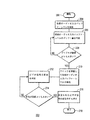
図3は、本発明の実施の形態に従った処理を示すフロー図である。この処理は、概ね参照符号200によって示される。ブロック202によって、処理が開始する。
FIG. 3 is a flowchart showing processing according to the embodiment of the present invention. This process is indicated generally by the
ブロック204において、初期オーディオ入力バッファ・レベルが判定される。ブロック206に示すように、時間が経過する際の初期オーディオ入力バッファ・レベルのドリフト量が判定される。ドリフトが第1の所定の閾値を超えると(ブロック208)、ロックされたビデオD/A変換器32(図1)およびオーディオD/A変換器34のクロックは、初期オーディオ入力バッファ・レベルを維持する方法で調整される。
At
クロックの調整に応じて、ブロック212に示すように、ビデオ信号の変位が測定される。ビデオ信号の変位が第2の所定の閾値を超えると(ブロック214)、例えば、同期を向上するために、処理を再スタートしたり、ビデオ・フレームをドロップしたりすることによって、測定されたビデオ信号の変位が打ち消される(ブロック216)。ブロック218において処理が終了する。
In response to the clock adjustment, the displacement of the video signal is measured, as shown in
本発明の態様に対し、様々な改変や変形が可能であるが、例示的に、図面において具体的な実施の形態が示され、本明細書において詳細に説明されている。しかしながら、本発明は、開示されている特定の態様に限定されるように意図されたものでないことを理解すべきである。むしろ、本発明は、付随する請求の範囲によって定義される発明の精神と範囲内に実施の形態の変形例、均等物、および代替物の全てが含まれるものである。 While various modifications and variations can be made to the aspects of the present invention, specific embodiments are shown by way of example in the drawings and are described in detail herein. However, it should be understood that the invention is not intended to be limited to the particular embodiments disclosed. On the contrary, the invention is intended to cover all modifications, equivalents, and alternatives of the embodiments within the spirit and scope of the invention as defined by the appended claims.
Claims (20)
初期オーディオ入力バッファ・レベルを判定するコンポーネント(34)と、
前記初期オーディオ入力バッファ・レベルにおけるドリフト量を判定し、当該ドリフト量が第1の所定の閾値に達している場合に前記クロックを調整することによって、前記初期オーディ入力バッファ・レベルを維持するコンポーネント(34)と、
前記クロックの調整に応じて前記オーディオ信号に関連付けられたビデオ信号(29)の変位を測定し、当該測定された変位が第2の所定の閾値に達している場合に前記ビデオ信号(29)の前記測定された変位を打ち消すように動作するコンポーネント(32)とからなる、システム。 In a system (23) that maintains synchronization between a video signal (29) and an audio signal (31) processed using a locked clock:
A component (34) for determining an initial audio input buffer level;
A component that maintains the initial audio input buffer level by determining a drift amount at the initial audio input buffer level and adjusting the clock when the drift amount reaches a first predetermined threshold ( 34)
A displacement of the video signal (29) associated with the audio signal is measured in response to the adjustment of the clock, and when the measured displacement reaches a second predetermined threshold, the video signal (29) A system comprising a component (32) that operates to cancel the measured displacement.
初期オーディオ入力バッファ・レベルを判定する手段(34)と、
前記初期オーディオ入力バッファ・レベルにおけるドリフト量を判定する手段(34)と、
前記ドリフト量が第1の所定の閾値に達している場合に前記クロックを調整することによって、前記初期オーディ入力バッファ・レベルを維持する手段(34)と、
前記クロックの調整に応じて前記オーディオ信号に関連付けられたビデオ信号(29)の変位を測定する手段(32)と、
当該測定された変位が第2の所定の閾値に達している場合に前記ビデオ信号(29)の前記測定された変位を打ち消す手段(32)とからなる、システム。 In a system (23) that maintains synchronization between a video signal (29) and an audio signal (31) processed using a locked clock:
Means (34) for determining an initial audio input buffer level;
Means (34) for determining a drift amount at the initial audio input buffer level;
Means (34) for maintaining the initial audio input buffer level by adjusting the clock when the amount of drift reaches a first predetermined threshold;
Means (32) for measuring the displacement of the video signal (29) associated with the audio signal in response to adjustment of the clock;
The system comprising means (32) for canceling the measured displacement of the video signal (29) when the measured displacement has reached a second predetermined threshold.
初期オーディオ入力バッファ・レベルを判定するステップ(204)と、
前記初期オーディオ入力バッファ・レベルにおけるドリフト量を判定するステップ(206)と、
前記ドリフト量が第1の所定の閾値に達している場合に前記クロックを調整することによって、前記初期オーディ入力バッファ・レベルを維持するステップ(210)と、
前記クロックの調整に応じて前記オーディオ信号に関連付けられたビデオ信号(29)の変位を測定するステップ(212)と、当該測定された変位が第2の所定の閾値に達している場合に前記ビデオ信号(29)の前記測定された変位を打ち消すステップ(216)とからなる、システム。 In a method (200) of maintaining synchronization between a video signal (29) and an audio signal (31) processed using a locked clock:
Determining an initial audio input buffer level (204);
Determining a drift amount at the initial audio input buffer level (206);
Maintaining the initial audio input buffer level by adjusting the clock when the drift amount reaches a first predetermined threshold (210);
Measuring a displacement (212) of the video signal (29) associated with the audio signal in response to the adjustment of the clock; and, if the measured displacement has reached a second predetermined threshold, the video. Canceling the measured displacement of the signal (29) (216).
Applications Claiming Priority (2)
| Application Number | Priority Date | Filing Date | Title |
|---|---|---|---|
| US42087102P | 2002-10-24 | 2002-10-24 | |
| PCT/US2003/033451 WO2004039056A2 (en) | 2002-10-24 | 2003-10-22 | A method and system for maintaining lip synchronization |
Publications (3)
| Publication Number | Publication Date |
|---|---|
| JP2006508564A true JP2006508564A (en) | 2006-03-09 |
| JP2006508564A5 JP2006508564A5 (en) | 2006-11-24 |
| JP4462549B2 JP4462549B2 (en) | 2010-05-12 |
Family
ID=32176641
Family Applications (1)
| Application Number | Title | Priority Date | Filing Date |
|---|---|---|---|
| JP2004547018A Expired - Fee Related JP4462549B2 (en) | 2002-10-24 | 2003-10-22 | Method and system for maintaining lip synchronization |
Country Status (9)
| Country | Link |
|---|---|
| US (1) | US20060007356A1 (en) |
| EP (1) | EP1554868A4 (en) |
| JP (1) | JP4462549B2 (en) |
| KR (1) | KR20050073482A (en) |
| CN (1) | CN100477802C (en) |
| AU (1) | AU2003284321A1 (en) |
| BR (1) | BR0315309A (en) |
| MX (1) | MXPA05004340A (en) |
| WO (1) | WO2004039056A2 (en) |
Cited By (1)
| Publication number | Priority date | Publication date | Assignee | Title |
|---|---|---|---|---|
| JPWO2010122626A1 (en) * | 2009-04-20 | 2012-10-22 | パイオニア株式会社 | Receiver |
Families Citing this family (10)
| Publication number | Priority date | Publication date | Assignee | Title |
|---|---|---|---|---|
| US7212248B2 (en) * | 2002-09-09 | 2007-05-01 | The Directv Group, Inc. | Method and apparatus for lipsync measurement and correction |
| AU2003286797A1 (en) * | 2002-11-07 | 2004-06-03 | Thomson Licensing S.A. | A system and method for determining lip synchronization between audio and video in a digitized environment using buffer calculation |
| US7519845B2 (en) | 2005-01-05 | 2009-04-14 | Microsoft Corporation | Software-based audio rendering |
| CN100437546C (en) * | 2005-06-30 | 2008-11-26 | 腾讯科技(深圳)有限公司 | Method for realizing audio-frequency and video frequency synchronization |
| JP2007124090A (en) * | 2005-10-26 | 2007-05-17 | Renesas Technology Corp | Information apparatus |
| US7948558B2 (en) * | 2006-09-29 | 2011-05-24 | The Directv Group, Inc. | Audio video timing measurement and synchronization |
| US7765315B2 (en) * | 2007-01-08 | 2010-07-27 | Apple Inc. | Time synchronization of multiple time-based data streams with independent clocks |
| DE102007045774B4 (en) * | 2007-09-25 | 2010-04-08 | Continental Automotive Gmbh | Method and device for synchronizing an image display in a motor vehicle |
| WO2009150578A2 (en) * | 2008-06-11 | 2009-12-17 | Koninklijke Philips Electronics N.V. | Synchronization of media stream components |
| US9565426B2 (en) | 2010-11-12 | 2017-02-07 | At&T Intellectual Property I, L.P. | Lip sync error detection and correction |
Family Cites Families (17)
| Publication number | Priority date | Publication date | Assignee | Title |
|---|---|---|---|---|
| US5596696A (en) * | 1993-05-10 | 1997-01-21 | Object Technology Licensing Corp. | Method and apparatus for synchronizing graphical presentations |
| CA2140850C (en) * | 1994-02-24 | 1999-09-21 | Howard Paul Katseff | Networked system for display of multimedia presentations |
| KR100207687B1 (en) * | 1995-12-09 | 1999-07-15 | 윤종용 | Decoder for use in mpeg system and audio/video synchronization method |
| JP3698376B2 (en) * | 1996-08-19 | 2005-09-21 | 松下電器産業株式会社 | Synchronous playback device |
| US6262776B1 (en) * | 1996-12-13 | 2001-07-17 | Microsoft Corporation | System and method for maintaining synchronization between audio and video |
| US5778218A (en) * | 1996-12-19 | 1998-07-07 | Advanced Micro Devices, Inc. | Method and apparatus for clock synchronization across an isochronous bus by adjustment of frame clock rates |
| JP3106987B2 (en) * | 1997-01-09 | 2000-11-06 | 日本電気株式会社 | Audio / video synchronous playback device |
| KR100235438B1 (en) * | 1997-02-04 | 1999-12-15 | 구자홍 | Compensation method and device for reproducing audio signal in optical disc |
| KR100224099B1 (en) * | 1997-05-30 | 1999-10-15 | 윤종용 | Synchronizer and Method of Audio / Video Signal |
| US5959684A (en) * | 1997-07-28 | 1999-09-28 | Sony Corporation | Method and apparatus for audio-video synchronizing |
| IL123906A0 (en) * | 1998-03-31 | 1998-10-30 | Optibase Ltd | Method for synchronizing audio and video streams |
| US6279058B1 (en) * | 1998-07-02 | 2001-08-21 | Advanced Micro Devices, Inc. | Master isochronous clock structure having a clock controller coupling to a CPU and two data buses |
| US6347380B1 (en) * | 1999-03-03 | 2002-02-12 | Kc Technology, Inc. | System for adjusting clock rate to avoid audio data overflow and underrun |
| US7031306B2 (en) * | 2000-04-07 | 2006-04-18 | Artel Video Systems, Inc. | Transmitting MPEG data packets received from a non-constant delay network |
| US6654956B1 (en) * | 2000-04-10 | 2003-11-25 | Sigma Designs, Inc. | Method, apparatus and computer program product for synchronizing presentation of digital video data with serving of digital video data |
| US7030930B2 (en) * | 2001-03-06 | 2006-04-18 | Ati Technologies, Inc. | System for digitized audio stream synchronization and method thereof |
| US6906755B2 (en) * | 2002-01-04 | 2005-06-14 | Microsoft Corporation | Method and apparatus for synchronizing audio and video data |
-
2003
- 2003-10-22 BR BR0315309-6A patent/BR0315309A/en not_active IP Right Cessation
- 2003-10-22 WO PCT/US2003/033451 patent/WO2004039056A2/en not_active Ceased
- 2003-10-22 MX MXPA05004340A patent/MXPA05004340A/en active IP Right Grant
- 2003-10-22 JP JP2004547018A patent/JP4462549B2/en not_active Expired - Fee Related
- 2003-10-22 US US10/531,695 patent/US20060007356A1/en not_active Abandoned
- 2003-10-22 EP EP03776502A patent/EP1554868A4/en not_active Withdrawn
- 2003-10-22 AU AU2003284321A patent/AU2003284321A1/en not_active Abandoned
- 2003-10-22 KR KR1020057005951A patent/KR20050073482A/en not_active Ceased
- 2003-10-22 CN CNB2003801012487A patent/CN100477802C/en not_active Expired - Fee Related
Cited By (1)
| Publication number | Priority date | Publication date | Assignee | Title |
|---|---|---|---|---|
| JPWO2010122626A1 (en) * | 2009-04-20 | 2012-10-22 | パイオニア株式会社 | Receiver |
Also Published As
| Publication number | Publication date |
|---|---|
| KR20050073482A (en) | 2005-07-13 |
| WO2004039056A2 (en) | 2004-05-06 |
| CN100477802C (en) | 2009-04-08 |
| WO2004039056A3 (en) | 2004-09-23 |
| BR0315309A (en) | 2005-08-16 |
| CN1703914A (en) | 2005-11-30 |
| EP1554868A4 (en) | 2011-06-01 |
| MXPA05004340A (en) | 2005-08-03 |
| AU2003284321A1 (en) | 2004-05-13 |
| EP1554868A2 (en) | 2005-07-20 |
| US20060007356A1 (en) | 2006-01-12 |
| JP4462549B2 (en) | 2010-05-12 |
| AU2003284321A8 (en) | 2004-05-13 |
Similar Documents
| Publication | Publication Date | Title |
|---|---|---|
| JP4482911B2 (en) | System and method for determining synchronization between an audio signal and a video signal | |
| CN101484939B (en) | Clock drift compensation techniques for audio decoding | |
| KR100298958B1 (en) | Synchronization arrangement for a compressed video signal | |
| US9876944B2 (en) | Apparatus, systems and methods for user controlled synchronization of presented video and audio streams | |
| US20050276282A1 (en) | Method of audio-video synchronization | |
| US8842218B2 (en) | Video/audio data output device and method | |
| JP4462549B2 (en) | Method and system for maintaining lip synchronization | |
| KR20020041189A (en) | Method and Device for the system time clock control from MPEG Decoder | |
| US7602813B2 (en) | Decoder device | |
| KR19980086039A (en) | Synchronizer and Method of Audio / Video Signal | |
| JP4903930B2 (en) | Signal processing device | |
| JP5244320B2 (en) | Clock generation apparatus and method | |
| JPH11112982A (en) | MPEG data receiving device | |
| US20080025345A1 (en) | Methods and Systems for Buffer Management | |
| WO2014064781A1 (en) | Digital broadcast receiving apparatus and digital broadcast receiving method | |
| KR100499519B1 (en) | Method for Controlling Audio Lip-Synchronization | |
| US20020042708A1 (en) | Method and apparatus for outputting a datastream processed by a processing device | |
| JP4874272B2 (en) | Video signal processing apparatus and video signal processing method | |
| EP0912065A2 (en) | Method and apparatus for re-timing a digital signal | |
| JPH08280008A (en) | Encoding method and apparatus | |
| JP2008067179A (en) | Receiving apparatus and encoded data reproduction method | |
| HK1034348B (en) | Synchronizing apparatus and method for a compressed audio/video signal receiver | |
| HK1044090A1 (en) | Apparatus and method for synchronizing a compressed video signal receiving system | |
| JP2008010912A (en) | Video decoding device |
Legal Events
| Date | Code | Title | Description |
|---|---|---|---|
| RD02 | Notification of acceptance of power of attorney |
Free format text: JAPANESE INTERMEDIATE CODE: A7422 Effective date: 20060720 |
|
| RD03 | Notification of appointment of power of attorney |
Free format text: JAPANESE INTERMEDIATE CODE: A7423 Effective date: 20060810 |
|
| A521 | Request for written amendment filed |
Free format text: JAPANESE INTERMEDIATE CODE: A523 Effective date: 20060927 |
|
| A621 | Written request for application examination |
Free format text: JAPANESE INTERMEDIATE CODE: A621 Effective date: 20060927 |
|
| RD04 | Notification of resignation of power of attorney |
Free format text: JAPANESE INTERMEDIATE CODE: A7424 Effective date: 20061115 |
|
| RD05 | Notification of revocation of power of attorney |
Free format text: JAPANESE INTERMEDIATE CODE: A7425 Effective date: 20080318 |
|
| RD04 | Notification of resignation of power of attorney |
Free format text: JAPANESE INTERMEDIATE CODE: A7424 Effective date: 20080415 |
|
| A131 | Notification of reasons for refusal |
Free format text: JAPANESE INTERMEDIATE CODE: A131 Effective date: 20090623 |
|
| A601 | Written request for extension of time |
Free format text: JAPANESE INTERMEDIATE CODE: A601 Effective date: 20090917 |
|
| A602 | Written permission of extension of time |
Free format text: JAPANESE INTERMEDIATE CODE: A602 Effective date: 20090929 |
|
| A521 | Request for written amendment filed |
Free format text: JAPANESE INTERMEDIATE CODE: A523 Effective date: 20091214 |
|
| TRDD | Decision of grant or rejection written | ||
| A01 | Written decision to grant a patent or to grant a registration (utility model) |
Free format text: JAPANESE INTERMEDIATE CODE: A01 Effective date: 20100210 |
|
| A01 | Written decision to grant a patent or to grant a registration (utility model) |
Free format text: JAPANESE INTERMEDIATE CODE: A01 |
|
| A61 | First payment of annual fees (during grant procedure) |
Free format text: JAPANESE INTERMEDIATE CODE: A61 Effective date: 20100212 |
|
| FPAY | Renewal fee payment (event date is renewal date of database) |
Free format text: PAYMENT UNTIL: 20130226 Year of fee payment: 3 |
|
| R150 | Certificate of patent or registration of utility model |
Free format text: JAPANESE INTERMEDIATE CODE: R150 |
|
| FPAY | Renewal fee payment (event date is renewal date of database) |
Free format text: PAYMENT UNTIL: 20130226 Year of fee payment: 3 |
|
| FPAY | Renewal fee payment (event date is renewal date of database) |
Free format text: PAYMENT UNTIL: 20140226 Year of fee payment: 4 |
|
| LAPS | Cancellation because of no payment of annual fees |