JP2006505434A - Pressure and temperature guidance in the in-mold coating process - Google Patents
Pressure and temperature guidance in the in-mold coating process Download PDFInfo
- Publication number
- JP2006505434A JP2006505434A JP2004551771A JP2004551771A JP2006505434A JP 2006505434 A JP2006505434 A JP 2006505434A JP 2004551771 A JP2004551771 A JP 2004551771A JP 2004551771 A JP2004551771 A JP 2004551771A JP 2006505434 A JP2006505434 A JP 2006505434A
- Authority
- JP
- Japan
- Prior art keywords
- mold
- coating
- thermoplastic
- injection
- pressure
- Prior art date
- Legal status (The legal status is an assumption and is not a legal conclusion. Google has not performed a legal analysis and makes no representation as to the accuracy of the status listed.)
- Pending
Links
Images


Classifications
-
- B—PERFORMING OPERATIONS; TRANSPORTING
- B29—WORKING OF PLASTICS; WORKING OF SUBSTANCES IN A PLASTIC STATE IN GENERAL
- B29C—SHAPING OR JOINING OF PLASTICS; SHAPING OF MATERIAL IN A PLASTIC STATE, NOT OTHERWISE PROVIDED FOR; AFTER-TREATMENT OF THE SHAPED PRODUCTS, e.g. REPAIRING
- B29C37/00—Component parts, details, accessories or auxiliary operations, not covered by group B29C33/00 or B29C35/00
- B29C37/0025—Applying surface layers, e.g. coatings, decorative layers, printed layers, to articles during shaping, e.g. in-mould printing
- B29C37/0028—In-mould coating, e.g. by introducing the coating material into the mould after forming the article
-
- B—PERFORMING OPERATIONS; TRANSPORTING
- B29—WORKING OF PLASTICS; WORKING OF SUBSTANCES IN A PLASTIC STATE IN GENERAL
- B29C—SHAPING OR JOINING OF PLASTICS; SHAPING OF MATERIAL IN A PLASTIC STATE, NOT OTHERWISE PROVIDED FOR; AFTER-TREATMENT OF THE SHAPED PRODUCTS, e.g. REPAIRING
- B29C45/00—Injection moulding, i.e. forcing the required volume of moulding material through a nozzle into a closed mould; Apparatus therefor
- B29C45/16—Making multilayered or multicoloured articles
- B29C45/1679—Making multilayered or multicoloured articles applying surface layers onto injection-moulded substrates inside the mould cavity, e.g. in-mould coating [IMC]
-
- B—PERFORMING OPERATIONS; TRANSPORTING
- B29—WORKING OF PLASTICS; WORKING OF SUBSTANCES IN A PLASTIC STATE IN GENERAL
- B29C—SHAPING OR JOINING OF PLASTICS; SHAPING OF MATERIAL IN A PLASTIC STATE, NOT OTHERWISE PROVIDED FOR; AFTER-TREATMENT OF THE SHAPED PRODUCTS, e.g. REPAIRING
- B29C45/00—Injection moulding, i.e. forcing the required volume of moulding material through a nozzle into a closed mould; Apparatus therefor
- B29C45/17—Component parts, details or accessories; Auxiliary operations
- B29C45/76—Measuring, controlling or regulating
- B29C45/77—Measuring, controlling or regulating of velocity or pressure of moulding material
Abstract
インモールドコーティング方法であって、コーティング基体が成型された基体の表面上に射出される時間が、型内部温度および/または内部圧力により決定される方法。インモールドコーティングが射出されるポイントを型内部温度および/または内部圧力に基づいて規制することにより、オペレーターは成型された基体の表面がインモールドコーティング接着に理想的な条件で、インモールドコーティングが射出されることを保証することができる。An in-mold coating method, wherein the time that the coated substrate is injected onto the surface of the molded substrate is determined by the mold internal temperature and / or internal pressure. By regulating the point at which the in-mold coating is injected based on the mold internal temperature and / or internal pressure, the operator can inject the in-mold coating under conditions that are ideal for in-mold coating adhesion. Can be guaranteed.
Description
発明の背景
本発明は、射出時間を管理するためにインモールドの温度および/または圧力を使用するインモールドコーティング方法へ関する。より詳細には、本発明は、コーティング基体が射出される時が型内部の温度および/または圧力によって決定されるインモールドコーティング方法に関する。本発明は、熱可塑性部材のインモールドコーティングに関して、特に用途を有する。しかしながら、本発明は他の類似の環境および用途にも関することが認識される。
The present invention relates to an in-mold coating method that uses in-mold temperature and / or pressure to control injection time. More particularly, the present invention relates to an in-mold coating method in which the time when a coated substrate is injected is determined by the temperature and / or pressure inside the mold. The present invention has particular application for in-mold coating of thermoplastic members. However, it will be appreciated that the invention also relates to other similar environments and applications.
成形された熱可塑性および熱硬化性の物品、たとえば、ポリオレフィン、ポリカーボネート、ポリエステル、ポリスチレンおよびポリウレタンから作られた物は、自動車、船舶、レクリエーション製品、構造物、オフィス製品、およびアウトドア装置産業をはじめとする多数の用途で利用される。しばしば、表面コーティングを成形された熱可塑性または熱硬化性の物品に適用することが望ましい。例えば、成形された物品は複数の部品のアセンブリーの中の1部分として使用されてもよい;そのようなアセンブリー中で他の部分と仕上げを適合させるためには、成形された物品は、他の部分と同じ仕上げ特性を有する表面コーティングの適用を必要とする場合がある。コーティングは、たとえば外観、光沢、耐引っかき性、耐薬品性、耐候性などの均一性のようなの成形品の表面特性を改善するためにも使用されることができる。さらに、表面被覆は成形品と、後でそれに適用される異なる仕上げコーティングとの間の接着を容易にするために使用されてもよい。 Molded thermoplastic and thermoset articles, such as those made from polyolefins, polycarbonates, polyesters, polystyrenes and polyurethanes, including the automotive, marine, recreational products, structures, office products, and outdoor equipment industries Used in many applications. Often, it is desirable to apply a surface coating to a molded thermoplastic or thermoset article. For example, the molded article may be used as one part in an assembly of multiple parts; to match the finish with other parts in such an assembly, the molded article It may be necessary to apply a surface coating with the same finishing properties as the part. The coating can also be used to improve the surface properties of a molded article, such as uniformity in appearance, gloss, scratch resistance, chemical resistance, weather resistance, and the like. Furthermore, the surface coating may be used to facilitate adhesion between the molded article and a different finish coating that is subsequently applied to it.
成形された物品に表面被覆を適用する多数の技術が開発されている。これらのうちの多数は成形物品を型から取り出した後、物品に表面被覆を適用することを含んでいる。これらの技術は、しばしば表面の調製と、それに引き続いて調製された表面をペイントもしくは他の仕上げ剤でスプレーコーティングすることを含む多段階プロセスである。対照的に、IMCは、表面コーティングを型からの取り出し前に成形品に適用する手段を提供する。 A number of techniques have been developed for applying surface coatings to molded articles. Many of these involve applying a surface coating to the article after the molded article is removed from the mold. These techniques are often multi-step processes involving the preparation of surfaces and subsequent spray coating of the prepared surfaces with paint or other finishes. In contrast, IMC provides a means for applying a surface coating to a molded article prior to removal from the mold.
歴史的には、IMCに関する多くの研究は熱硬化材料から作られた物品についてなされた。フェノール樹脂、エポキシ樹脂、架橋可能なポリエステル樹脂のような熱硬化性樹脂は、それらが流動状態において化学的に反応し、ポリマー鎖の架橋を引き起こす反応により硬化されるプラスチック複合材料の種類である。一旦硬化されると、引き続く加熱が熱硬化物を柔らかくするが、流動状態には戻らない。 Historically, much research on IMC has been done on articles made from thermoset materials. Thermosetting resins such as phenolic resins, epoxy resins, and crosslinkable polyester resins are a class of plastic composites that are cured by a reaction that causes them to chemically react in the flow state and cause crosslinking of the polymer chains. Once cured, subsequent heating softens the thermoset but does not return to a fluid state.
より最近では、熱可塑性物質から作られたIMC物品に興味がもたれている。熱可塑性物質は、溶融することができ、冷却により固形化し、繰り返し再溶融と再固形化のできる種類のプラスチック材料である。多くの熱可塑性の材料の物理的・化学の特性は、それらの成形の容易さと相まって、自動車、船舶、レクリエーション製品、構造物、オフィス製品、およびアウトドア装置産業をはじめとする多数の用途でそれらを利用させる。 More recently, there has been interest in IMC articles made from thermoplastic materials. Thermoplastics are a type of plastic material that can be melted, solidified by cooling, and repeatedly remelted and resolidified. The physical and chemical properties of many thermoplastic materials, coupled with their ease of molding, make them useful in numerous applications including automotive, marine, recreational products, structures, office products, and outdoor equipment industries. Make it available.
成形された熱硬化性物品および熱可塑性物品にコーティングを適用するために様々な方法が使用されてきた。例えば、コーティングを開いた型の表面にスプレーした後、型を閉じることができる。しかしながら、スプレーコーティングは時間がかかり、揮発性の有機媒体を使用してコーティングが塗布される場合、封じ込めシステムの使用が必要とされる場合がある。他のコーティングプロセスは、成形に先立ってあらかじめ形成されたコーティングのフィルムで型をライニングすることを含んでいる。このプロセスの欠点は、工業規模においては、それが煩わしく、高価になりえるということである。 Various methods have been used to apply coatings to molded thermoset and thermoplastic articles. For example, the mold can be closed after spraying the coating onto the surface of the open mold. However, spray coating is time consuming and may require the use of a containment system when the coating is applied using a volatile organic medium. Another coating process involves lining the mold with a film of a pre-formed coating prior to molding. The disadvantage of this process is that it can be cumbersome and expensive on an industrial scale.
流体のコーティングが成型された物品の表面上に射出され、分散され、硬化されるプロセスも開発されている。成形品の表面上へ流動性IMCを射出する一般的な方法は、硬化(熱硬化性物質の場合)および型内の物品をコーティングを十分に受容する堅さまで冷却し、はまりこんでいる半型に対する圧力を低下させ、型を割り開くかまたは離し、流体コーティングを射出し、型を再加圧し、コーティングを成型された物品の表面上に分配することを含む。型の割り開きまたは分離は、はまりこんでいる半型に対して加えられている圧力を開放し、半型を成型された物品から離し、それにより部材の表面とはまりこんでいる半型との間に隙間を作ることを含む。ギャップは、コーティングが型から部材を取り除く必要なしに、その部材の表面上に射出されることを可能にする。 A process has also been developed in which a fluid coating is injected, dispersed and cured onto the surface of a molded article. A common method of injecting flowable IMC onto the surface of a molded article is to cure (in the case of a thermosetting material) and cool the article in the mold to a hardness sufficient to receive the coating, against a half mold Reducing pressure, cleaving or releasing the mold, injecting a fluid coating, repressurizing the mold, and dispensing the coating onto the surface of the molded article. The splitting or separation of the mold relieves the pressure applied to the mold half that is stuck and separates the mold half from the molded article, so that the surface of the part is between the mold half that is stuck. Including creating a gap. The gap allows the coating to be injected onto the surface of the member without having to remove the member from the mold.
射出成型のような他のプロセスは、移動可能な半型上の圧力が維持され、キャビティーを閉鎖状態に保ち、樹脂がパーティングラインに沿って漏れることを防止することを必要とする。成形中に樹脂の材料に対する圧力を維持して、キャビティーを閉じた位置に維持することが、しばしば成形物品のより均一な結晶化または分子構造の補助のために必要とされる。そのような充填をしないと、成形された物品の物理特性が損なわれる傾向がある。 Other processes, such as injection molding, require that the pressure on the movable mold be maintained, keeping the cavity closed and preventing the resin from leaking along the parting line. Maintaining the pressure on the resin material during molding to maintain the cavity in a closed position is often required to aid in more uniform crystallization or molecular structure of the molded article. Without such filling, the physical properties of the molded article tend to be impaired.
パーティングラインに沿って樹脂が漏れるという問題に加えて、IMC組成物が成形品を含む型内に射出される場合、充填の制約は時々他の問題を引き起こす場合がある。特に、いくつかの商業的に利用可能なIMCは一般に熱硬化性の材料であり、熱を加えることによって硬化する。これらの組成物の硬化は、成形品からの残余の熱の伝達を通じてしばしば達成される。成型された物品が十分に充填され、型を減圧して分離または割り開いた後にコーティング組成物が射出される場合、成形品は、コーティングを硬化するための十分な残余の熱を欠くことがある。したがって、物品上で硬化するように設計されたコーティング組成物については、望ましくは、型を減圧するに前に射出される。 In addition to the problem of resin leaking along the parting line, filling constraints can sometimes cause other problems when the IMC composition is injected into a mold containing the molded article. In particular, some commercially available IMCs are generally thermosetting materials that cure upon application of heat. Curing of these compositions is often accomplished through the transfer of residual heat from the molded article. If the molded article is fully filled and the coating composition is injected after the mold is decompressed and separated or split, the molded article may lack sufficient residual heat to cure the coating . Thus, for a coating composition designed to cure on an article, it is desirably injected prior to depressurizing the mold.
型キャビティー内へのIMC組成物の射出の前に型を離したり割り開いたりすることは射出成形では許されないので、IMC組成物はコーティングされるすべての領域において物品を圧縮するのに十分な圧力下で射出されなければならない。成形品の圧縮性は、IMC組成物が成形品のどこを、どのように被覆するかを決定する。射出成形された物品を液体IMC組成物でコーティングするプロセスは、たとえば、米国特許第6,617,033号、米国特許公開第2002/0039656A1号および2003/0082344A1号に記載されている。 The IMC composition is sufficient to compress the article in all areas to be coated, as it is not permitted in injection molding to release or split the mold prior to injection of the IMC composition into the mold cavity. Must be injected under pressure. The compressibility of the molded article determines where and how the IMC composition covers the molded article. Processes for coating injection molded articles with liquid IMC compositions are described, for example, in US Pat. No. 6,617,033, US Patent Publication Nos. 2002 / 0039656A1 and 2003 / 0082344A1.
射出成型された熱可塑性物品をコーティングするために液体インモールドコーティングを使用する場合に、許容可能な部材性能および特性を保証するためにモニターされ制御されなければならない1つの重要なパラメータは、成形プロセスにおいてキャビティー内にインモールドコーティングを射出する正確なタイミングである。より詳細に以下において議論されるように、インモールドコーティングは、好ましくは、型壁に隣接する熱可塑性基体の表面が、ちょうどその溶融温度以下となるそのポイントで型内に射出される。このポイントでは、熱可塑性物質はIMCを受容するのに十分堅く、熱可塑性基体をIMCが完全にコーティングするのに十分な圧縮性を依然として保持している。 When using liquid in-mold coatings to coat injection molded thermoplastic articles, one important parameter that must be monitored and controlled to ensure acceptable member performance and properties is the molding process. Is the precise timing to inject the in-mold coating into the cavity. As discussed in more detail below, the in-mold coating is preferably injected into the mold at that point where the surface of the thermoplastic substrate adjacent to the mold wall is just below its melting temperature. At this point, the thermoplastic is stiff enough to receive IMC and still retains sufficient compressibility for the IMC to completely coat the thermoplastic substrate.
したがって、IMCが型内に射出される成形プロセスでの正確な段階を制御し、熱可塑性物質がちょうどその融点以下に冷却されたポイントで、IMCが射出されることを保証する方法に対する必要性があった。これは、型内の圧力および/または温度をモニタし、圧力および/または温度が熱可塑性物質の十分な冷却を示す最適値に達したポイントでIMCを射出する本発明により達成される。 Therefore, there is a need for a method that controls the exact stage in the molding process in which the IMC is injected into the mold and ensures that the IMC is injected at the point where the thermoplastic is cooled just below its melting point. there were. This is accomplished by the present invention in which the pressure and / or temperature in the mold is monitored and the IMC is injected at the point where the pressure and / or temperature has reached an optimal value indicating sufficient cooling of the thermoplastic.
発明の簡単な説明
第1の実施態様では、本発明は、インモールドコーティングプロセスにおいて型内の成形品の表面と接触させるためにコーティングを射出する時を決定するための方法に関し、この方法は型が所定量の熱可塑性物質で満たされた後に型の内部の圧力を決定する工程;
熱可塑性物質が型内で冷却されるときの型の内部圧力を経時的にモニターする工程;
型の内部圧力の変化から、熱可塑性物質の表面がその融点以下に冷却したことを決定する工程を含む。
BRIEF DESCRIPTION OF THE INVENTION In a first embodiment, the present invention relates to a method for determining when to inject a coating to contact a surface of a molded article in a mold in an in-mold coating process, the method comprising: Determining the pressure inside the mold after the is filled with a predetermined amount of thermoplastic;
Monitoring the internal pressure of the mold over time as the thermoplastic cools in the mold;
Determining from the change in the internal pressure of the mold that the surface of the thermoplastic has cooled below its melting point.
第2の実施態様においては、本発明は熱可塑性基体をインモールドコーティングする方法に関し、該方法は型内部温度および型内部圧力の少なくとも1つをモニターしながら、熱可塑性基体を閉じられた型内に射出する工程;
熱可塑性基体の表面をその融点以下に冷却させ、成型された物品を形成する工程;
コーティングを閉じられた型内に射出し、コーティングか熱可塑性基体の表面の少なくとも一部と接触させる工程を含み、ここでコーティングは型内部温度および型内部圧力の少なくとも1つが、熱可塑性基体がその融点以下に冷却されたことを示したポイントで射出される。
In a second embodiment, the present invention relates to a method for in-mold coating a thermoplastic substrate, wherein the method monitors at least one of a mold interior temperature and a mold interior pressure while the thermoplastic substrate is in a closed mold. Injecting into
Cooling the surface of the thermoplastic substrate below its melting point to form a molded article;
Injecting the coating into a closed mold and contacting the coating or at least a portion of the surface of the thermoplastic substrate, wherein the coating is at least one of a mold interior temperature and a mold interior pressure, wherein the thermoplastic substrate is Injected at the point indicating cooling to below the melting point.
図面の簡単な説明
本発明は、様々な物理的形態の構成要素、および構成要素の配置を取ることができ、種種の工程および工程の配列を取ることができる。図面は本発明の好ましい実施態様を例示するものであり、本発明を何ら制限するものではない。
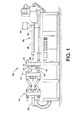
図1は、本発明の1つの実施態様で使用するに適当な移動可能な半型、および静止した半型を有する、成形装置の側面図である。
図2は、図1の成形装置の部分断面図を示し、移動可能な半型および静止している半型を示し、ここで移動可能な半型が閉じた位置にあり型キャビティーを形成し、型キャビティーは第1および第2の組成物インジェクターを受容するためにオリフィスを有している。
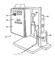
図3は、本発明の1つの実施態様を実行する際に使用するにふさわしい、図1の成形装置に接続されるように適応された、インモールドコーティングの供給および制御装置の透視図である。
図4は典型的な熱可塑性基体における、圧力−比容−温度(PVT)の関係を示すグラフである。
BRIEF DESCRIPTION OF THE DRAWINGS The present invention can take various physical forms of components and arrangements of components, and can take various steps and arrangements of steps. The drawings illustrate preferred embodiments of the invention and are not intended to limit the invention in any way.
FIG. 1 is a side view of a molding apparatus having a movable mold half suitable for use in one embodiment of the present invention and a stationary mold half.
2 shows a partial cross-sectional view of the molding apparatus of FIG. 1, showing a movable half mold and a stationary half mold, wherein the movable half mold is in a closed position to form a mold cavity. The mold cavity has an orifice for receiving the first and second composition injectors.
FIG. 3 is a perspective view of an in-mold coating supply and control device adapted to be connected to the molding apparatus of FIG. 1, suitable for use in practicing one embodiment of the present invention.
FIG. 4 is a graph showing a pressure-specific volume-temperature (PVT) relationship in a typical thermoplastic substrate.
発明の詳細な説明
以下において図面が参照されるが、開示は本発明の好ましい実施態様を示す目的のためのみに行われる。図1は、成形装置または射出成形機10を示し、その操作において本発明は特に有用性を有する。成形装置10は、第1の半型12を有し、これは好ましくは第2の移動可能な半型14に対して静止しているあるいは固定された位置にある。図1は開放された位置にある移動可能な半型14を示す。第1の半型12および第2の半型14は互いにかみ合うように適合され、その間に型キャビティー16を形成する(図2参照)。半型12、14は表面18および20に沿ってかみ合い(図1)、成形装置が閉じた位置にある場合に、それらの間および型キャビティー16の周囲にパーティングライン22(図2)を形成する。
DETAILED DESCRIPTION OF THE INVENTION In the following, reference is made to the drawings, but the disclosure is made solely for the purpose of illustrating preferred embodiments of the invention. FIG. 1 shows a molding apparatus or
クランプメカニズム24とクランプアクチュエーター26の運動、たとえば、公知のような液圧、または空気圧アクチュエーターを介する運動により、可動の半型14は、第1のもしくは固定された半型12に対してほぼ水平な軸に沿って往復運動する。クランプメカニズム24によって加えられるクランプ圧力は、1対の組成物のインジェクター30および32のいずれかにより発生又は加えられる圧力よりも大きなクランプ圧力を有するべきである。好ましい実施態様においては、クランプ機構24によって加えられる圧力は、型表面に対して約2,000ポンド/平方インチ(psi)もしくは13.8MPaから約15,000psiもしくは103.3Mpa、好ましくは約4,000psiもしくは27.6MPaから約12,000psiもしくは82.7MPa、さらに好ましくは約6,000psiもしくは41.3MPaから約10,000psiもしくは68.9MPaまでの範囲である。
Due to the movement of the
図2では、2つの半型12と14は閉じた位置で示され、パーティングライン22に沿って、互いに接するかまたは噛み合い、型キャビティー16を形成する。キャビティーのデザインは、所望の最終生成物または成形される物品により、サイズおよび形が非常に異なることができることは当業者に容易に理解できる。型キャビティー16は、一般に第2の半型14の上に第1の表面34を有し、第1の半型12の上に相対する第2の表面36を有する。型キャビティーは異なるオリフィス38、40を有し、組成物インジェクター30、32がそれぞれの組成物を内部に射出できるようにする。
In FIG. 2, the two dies 12 and 14 are shown in a closed position and abut or mesh with each other along the
図1を再度参照すれば、第1の組成物インジェクター30は、当該技術分野において公知の典型的な射出成型装置である。一般に第1の組成物インジェクター30は、型キャビティー16の中へ、一般に樹脂またはポリマーである、熱可塑性または熱硬化性基体組成物を射出することができる。空間的な制限のために、熱可塑性物質を射出するために使用される第1のインジェクター30は固定半型12から材料を射出するように位置する。第1の組成物インジェクター30を逆にすることができ、移動可能な半型に配置することができることが理解されるべきである。同様に第2の組成物インジェクター32は移動可能な半型14に位置して示されているが、別法として固定半型12の上に位置することができることが理解されるべきである。
Referring back to FIG. 1, the
第1の組成物インジェクター30は「バックオフ」位置で示される。しかし、これは水平方向に動くことができ、第1のインジェクターのノズルまたは樹脂出口42が半型12と噛み合うことが容易に理解できる。かみ合った位置で、インジェクター30が型キャビティー16内にその含有物を射出することができる。例示のみの目的のために、第1の組成物インジェクター30はレシプロケーティングスクリュー機械として示され、ここで第1の組成物はホッパー44内に置かれることができ、回転するスクリュー46は組成物を加熱された押し出しバレル48を通して動かし、ここで第1の組成物または物質はその融点以上に加熱される。加熱された物質がバレルの端の近傍に集まると、スクリュー46は射出ラムの役割をし、ノズル42を通して物質を型キャビティー16内へ入れる。ノズル42は、一般にそれの開放端に逆止弁(図示せず)を有し、スクリュー46は、材料の逆流を防ぐために逆止弁(図示せず)を有する。
The
第1の組成物インジェクターは、図1の中で示される実施態様に制限されるものではなく、型キャビティー内に熱可塑性組成物を射出することができる任意の装置でありえる。例えば、射出成形機は、中心射出の「スタック型」におけるように、垂直方向において移動可能な半型を有することができる。他の適当な射出成形機としては、Cincinnati−Milacron社(オハイオ州、シンシナチ)、Battenfeld Gloucester Engineering社(マサチューセッツ州、グラウセスター)、Engel Machinery社(ペンシルバニア州、ヨーク)、Husky Injection Molding Systems社(カナダ、ボルトン)、Boy Machines社(ペンシルバニア州、エクストン)その他から利用可能である。 The first composition injector is not limited to the embodiment shown in FIG. 1 and can be any device capable of injecting the thermoplastic composition into the mold cavity. For example, an injection molding machine may have a half mold that is movable in the vertical direction, such as in a central injection “stacked mold”. Other suitable injection molding machines include Cincinnati-Milacron (Cincinnati, Ohio), Battenfeld Gloucester Engineering (Grousester, Massachusetts), Engel Machinery (olst, Pennsylvania, York) Bolton), Boy Machines (Exton, PA) and others.
図3を参照すると、インモールドコーティングの供給および制御装置60は、成形装置10に接続可能で、成形装置10にインモールドコーティングの能力および制御を提供する。制御装置60は、インモールドコーティング組成物のバットのような、インモールドコーティングコンテナを支持するためのインモールドコーティングコンテナ受容シリンダー62を含む。適当なインモールドコーティング組成物としては、米国特許第5,777,053号に開示されているものが挙げられる。制御装置60は、受容シリンダー62に受容された時にインモールドコーティングコンテナとの流体コミュニケーションを有するように適応された計量シリンダーまたはコンテナ64をさらに含んでいる。移送ポンプ66が制御装置60に提供され、これは以下において詳述されるように、受容シリンダーから計量シリンダー64にインモールドコーティング組成物を移送することができる。
Referring to FIG. 3, an in-mold coating supply and
計量シリンダー64は、成形装置10の第2のインジェクター32に選択的に流体的に連結可能である。計量シリンダー64は、計量シリンダー64からインモールドコーティング組成物を空にして、第2のインジェクター32にインモールドコーティング組成物を導くための液圧ピストンのような液圧手段を含んでいる。戻しライン(図示せず)は、第2のインジェクター32と受容シリンダー62に接続され、これらの間を流体的に連結する。
The metering cylinder 64 can be selectively fluidly connected to the
制御装置60は、動力源に接続することができる電気ボックス74をさらに含んでいる。電気ボックス74は、後に詳述されるように、インモールドコーティング組成物の成形装置10の型キャビティー16への供給の制御のために複数の制御盤76およびタッチパッドまたは他のタイプのコントローラ78を有する。圧縮空気コネクター(図示せず)は、公知の圧縮空気ラインに制御装置60を接続するために制御装置上に提供される。圧縮空気は、移送ポンプ66を運転し、かつ「クリーンアウト」操作中に制御装置およびその流体連絡にある配管からインモールドコーティング組成物を取り除くために使用される。さらに、空気は清浄化の目的のために、流体連絡にある配管から溶剤を取り除くために使用される。
The
供給および制御装置60は、好ましい実施態様においては半型12および14のうちの1つの上に配置されるように適応されるリモートの発信機(図示せず)を有することができる。発信機は、例えば操作時に制御装置へ信号を送る公知のロッカスイッチであることができる。発信機は、半型12,14の1つの上に置かれることができ、半型の閉鎖時に稼働されることができる。発信機から送られた信号は制御装置上でタイマー(図示せず)を開始するために使用される。
The supply and
別法として、成形装置10は半型12、14が閉じる際に信号を発生することができる発信機または発信機手段を装備することができる。そのような発信機は公知である。制御装置60に信号を伝えるために、公知の信号伝達ケーブルが成形装置10と制御装置60の間に接続されることができる。そのような配置は、半型の1つに独立した発信機を接続する必要を除去するだろう。
Alternatively, the
制御装置は少なくとも1つのリモートセンサー(図示せず)を好ましくは有する。リモートセンサーは型キャビティー16内の内部圧力および/または温度を測定または記録するために、型の1つの上に配置される。センサーは公知の任意のタイプのものであることができ、たとえば、圧力変換器または熱電対などであることができる。1つまたは複数のセンサーおよび制御装置60は公知の手段により操作可能に接続され、それらの間を測定信号が通ることを許容する。
The control device preferably has at least one remote sensor (not shown). A remote sensor is placed on one of the molds to measure or record the internal pressure and / or temperature within the
型キャビティー内にインモールドコーティング組成物を射出する準備をするために、所望のインモールドコーティング組成物のインモールドコーティングコンテナが受容シリンダー62内に置かれる。計量シリンダー64は、第2のインジェクター32に流体的に接続される。戻しライン88は、第2のインジェクター32および受容シリンダー62に流体的に接続される。電気ボックス74に電力を供給するために、制御装置60は、公知の460ボルトのACあるいはDC電源のような適切な動力源に接続される。上に記述されるように、リモートセンサーは、半型12、14のうちの1つに適切に配置される。
In preparation for injecting the in-mold coating composition into the mold cavity, an in-mold coating container of the desired in-mold coating composition is placed in the receiving
インモールドコーティングされた熱可塑性物品を作るために、図1に示されるように、熱可塑性の第1の組成物が成形装置10のホッパー44内に置かれる。第1のインジェクター30は、固定半型12と入れ子になるかまたはかみ合うように移動される。公知の手段を介して、つまり加熱された押し出しバレル48と回転スクリュー46を使用して、第1のインジェクター30は第1の組成物をその融点以上に加熱し、加熱された第1の組成物を第1のインジェクター30のノズル42へ導く。半型12、14は閉鎖され、それにより実質的に固定された体積の型キャビティー16を作る。上に記述されるように、制御装置60の発信器は半型のうちの1つに配置され、半型がともに閉まっている場合、発信器が半型が閉まっており、成形プロセスが始まったことを示す信号を制御装置60へ送る。
To make an in-mold coated thermoplastic article, a first thermoplastic composition is placed in the
信号を受取ると、以下この時間を時間T0と呼ぶ、供給および制御装置60は、その内部に含まれていたタイマーを作動させる。タイマーはT0からの経過時間を追跡するために使用される。あらかじめ定義された経過時間間隔で、制御装置60が始動され、種種のインモールドコーティングに関連する関数を制御し、成形プロセスにおいて所望の点で型キャビティー16にインモールドコーティング組成物が供給されることを保証する。したがって、制御装置60は成形装置10と同時に操作される。
Upon receiving the signal, hereinafter referred to as the time and the time T 0, the supply and
T0の後に、成形プロセスは継続し、ノズル42のノズルバルブ(図示せず)は、あらかじめ決定された時間の間、開放位置に移動され、対応する量の第1の組成物がオリフィス38を介して型キャビティー16に入るようにする。スクリュー46は、ノズルピンがその閉じた位置に戻るまで、型キャビティー16内へ第1の組成物を推進させ、または射出する力または圧力を提供する。当該技術分野において公知のように、第1の組成物は型キャビティー16内に満たされ、充填される。一旦型キャビティー16が満たされ充填されれば、成形された第1の組成物はその融点以下の温度に冷却される。当業者に理解されるように、熱可塑性物質は均一には冷却せず、成型された物品の内部は一般に溶融したままである一方、表面はより早く冷却されるので堅くなり始める。
After T 0 , the molding process continues and the nozzle valve (not shown) of
型の中の基体を成形するために使用される熱可塑性物質の射出は、3段階プロセスとして見ることができる。第1段階は充満段階と呼ばれる。この段階では、所定量の熱可塑性物質が型内に射出され、型をほぼ充満するまで、好ましくはその容量の少なくとも約75%まで型に射出される。第2の段階は充填段階と呼ばれる。この段階では、さらなる熱可塑性物質が型キャビティーを満たすために型に充填され、好ましくは、その容量の少なくとも約99%まで詰められる。第3の段階は冷却段階と呼ばれる。この段階では、それが冷え始めるとともに、熱可塑性物質は固形化し始める。 The injection of the thermoplastic material used to mold the substrate in the mold can be viewed as a three stage process. The first stage is called the filling stage. At this stage, a predetermined amount of thermoplastic material is injected into the mold and injected into the mold until it is almost full, preferably at least about 75% of its capacity. The second stage is called the filling stage. At this stage, additional thermoplastic material is filled into the mold to fill the mold cavity and is preferably packed to at least about 99% of its capacity. The third stage is called the cooling stage. At this stage, the thermoplastic begins to solidify as it begins to cool.
典型的な熱可塑性基体の圧力−比容−温度(PVT)関係が図4に示される。図4から射出圧力は熱可塑性物質の充満段階(0−1)の中で上昇することがわかる。充填段階においては、型内により多量の熱可塑性材料を射出することの結果として、充填圧力が上昇し(1−2)、熱可塑性物質が冷却を開始する時には、温度の低下により引き起こされる物質の収縮を補償するために、その後しばらく一定となる(2−3)。熱可塑性物質の冷却段階中に、熱可塑性物質が冷えて収縮を開始するので、型キャビティー中の圧力は減少する(3−4)。IMCコーティングが型内に射出されるのは、熱可塑性物質の冷却段階(3−4)中にである。 The pressure-specific volume-temperature (PVT) relationship for a typical thermoplastic substrate is shown in FIG. It can be seen from FIG. 4 that the injection pressure rises during the filling phase (0-1) of the thermoplastic material. In the filling stage, as a result of injecting more thermoplastic material into the mold, the filling pressure increases (1-2) and when the thermoplastic starts to cool, In order to compensate for the contraction, it becomes constant for a while thereafter (2-3). During the thermoplastic cooling phase, the pressure in the mold cavity decreases (3-4) as the thermoplastic cools and begins to shrink. It is during the thermoplastic cooling phase (3-4) that the IMC coating is injected into the mold.
射出後、型キャビティー中の樹脂は少なくともある程度まで固形化し始め、基体がコーティング組成物の導入による生じる射出および/または流動圧力に耐えることができるようになる。この固形化中に、成形物品は幾分冷却され、少なくとも若干の収縮が起こると信じられる。つまり、小さなギャップが成形物品と表面34および36の間に作成される。明白に、表面34および36から離れる成形物品のあるタイプの能動的な運動が起こることがあるが、必ず起こるのか否かは不明である。射出された熱可塑性物質が適切なモジュラスを達成した後、コーティング組成物を射出することができる。あらかじめ決定された量のコーティング組成物が、たとえば所望の厚さおよび密度を有するコーティングを提供するために利用される。
After injection, the resin in the mold cavity begins to solidify to at least some extent, allowing the substrate to withstand the injection and / or flow pressure that results from the introduction of the coating composition. During this solidification, the molded article is believed to cool somewhat and at least some shrinkage occurs. That is, a small gap is created between the molded article and the
上述のように、好ましくは基体の表面が十分に冷えて堅くなるまで待って、インモールドコーティングと熱可塑性物質が過度にインターミングルしないようにする。さらに、熱可塑性物質の充填とコーティングの射出との間の時間を長くすると、一般にコーティングを射出するために必要とされる充填圧力が低下し、射出がより容易になる。しかしながら、インモールドコーティングは一般に硬化のために冷却される熱可塑性物質の残余の熱に依存するので、待機期間が長すぎると、インモールドコーティングの硬化が不適正になるというリスクがある。さらに、熱可塑性物質は、インモールドコーティングと基体との間の十分な接着を許容するとともに、型内の基体表面の周囲にインモールドコーティングが適当に流れるように十分な圧縮性を提供することができるように、十分に溶融されていることが必要である。したがって、インモールドコーティングの適切な硬化を得るために、十分な残余の熱の必要と、コーティングの射出する容易さのバランスを取る必要がある。 As noted above, preferably the substrate surface is waited until it is sufficiently cooled and stiff to prevent the in-mold coating and the thermoplastic material from excessively intermingling. Furthermore, increasing the time between filling the thermoplastic and injecting the coating generally reduces the filling pressure required to inject the coating and makes injection easier. However, since in-mold coatings generally rely on the residual heat of the thermoplastic material that is cooled for curing, there is a risk that in-mold coatings will be improperly cured if the waiting period is too long. In addition, the thermoplastic material may allow sufficient adhesion between the in-mold coating and the substrate and provide sufficient compressibility so that the in-mold coating flows properly around the substrate surface in the mold. It needs to be sufficiently melted so that it can. Therefore, in order to obtain proper curing of the in-mold coating, it is necessary to balance the need for sufficient residual heat with the ease of injection of the coating.
第1の組成物が型キャビティー16内に射出され、コーティングされる成形品の表面が融点以下に冷えたか、そうでなければインモールドコーティングを受容または支持するのに十分な温度もしくは弾性率に達した後であるが、表面が冷却されすぎてインモールドコーティングの硬化が禁じられる前に、あらかじめ決定された量のインモールドコーティングが第2の組成物もしくはインモールドコーティングインジェクター32のオリフィス40(図2)から型キャビティーへ導入される準備がされる。
The first composition is injected into the
成形過程中のこのポイントは特定の型内部圧として特徴づけられる。特に、上記のように、1つの実施態様では、センサーは様々な間隔で制御装置60へ型キャビティー中の内圧を示す信号を送る圧力変換器であることができる。これらの信号は、熱可塑性基体が十分に冷却され、IMCが射出されることが可能であることを決定するために使用することができる。上述されるように、熱可塑性物質の表面がその溶融温度に十分に達するまで冷却された後、IMCはすぐに射出されるべきである。溶融温度にいつ到達したかの決定は、内部型圧力についての観察により行うことができる。成形品がその溶融温度に達して固形化し始める時、それは多少収縮し、それにより、型の中の圧力が減少する。これは型の中の圧力変換器の使用を通じて記録される。特定の熱可塑性物質が固形化し始める正確な圧力値は、成形過程の中で使用されている熱可塑性物質のタイプに明らかに依存する。個々の熱可塑性物質に対する具体的な値は、たとえば、図4に示されたようなそれらの熱可塑性物質のPVTチャートから、または実験的に決定することができる。
This point during the molding process is characterized as a specific mold internal pressure. In particular, as described above, in one embodiment, the sensor can be a pressure transducer that sends a signal to the
あらかじめ決定された内圧で制御装置60は始動され、種種のインモールドコーティングに関連する機能を制御し、以下においてTIMCと呼ばれる成形プロセスにおける所望の点でインモールドコーティングが型キャビティー16内に供給されることを保証する。したがって、装置60は、成形装置10に付随して作動する。
Is the
そのような1つの機能は、所望の量のインモールドコーティングで計量シリンダー64を充填することである。この機能はTIMCに先だって起こる。したがって、正確な瞬間に、制御装置60はバルブ(図示せず)を開き、インモールドコーティングが充填されたコンテナと計量シリンダー64の間の流体コミュニケーションを許容する。移送ポンプ66はコンテナから計量シリンダーにインモールドコーティング組成物を移送する。計量シリンダー64が所望の量で満たされた時、バルブは閉じ、より多くのインモールドコーティング組成物がシリンダーに入るのを防ぐ。以下に詳述されるように、シリンダー64に入ることを許されたIMC組成物の量は選択的に調整可能である。
One such function is to fill the metering cylinder 64 with the desired amount of in-mold coating. This function takes place prior to T IMC. Thus, at the precise moment, the
計量シリンダー64が充填された後、TIMCの直前に、制御装置60が、第2のインジェクター32のピンまたは弁(図示せず)を開け、第2のインジェクター32と型キャビティー16の間の流体連絡を許容する。弁は通常閉鎖位置に対してバイアスがかけられ、または閉鎖位置に対して促進され、すなわち型表面にフラッシュされるが、制御装置60により開放位置に選択的に移動可能である。特には、制御装置60の電気的に動力が供給された液圧ポンプ(図示せず)がピンを移動させるために使用される。その後すぐに、所定量の型内部圧力に到達したら、計量シリンダー64の液圧手段はその内部に含まれるインモールドコーティング組成物を空にし、インモールドコーティングを第2のインジェクター32に供給し、それはオリフィス40を通過して型キャビティー16内に入る。
After the metering cylinder 64 is filled, just prior to TIMC , the
一旦コーティング組成物が型キャビティー16内に射出されたら、第2のインジェクター32は非活性化され、したがってコーティング組成物の流れを止める。コーティング組成物は成型された物品の周囲を流れ、その表面に接着する。コーティング組成物の硬化または架橋は基体もくしは半型の残余の熱、もしくは組成物の成分の反応により起こる。インモールドコーティングはついで型キャビティー内で硬化し、これが適用された基体表面に接着する。硬化は基体もくしは半型の残余の熱、および/またはコーティング組成物の成分の間の反応により起こる。基体の残余の熱が硬化を起こすために使用される場合、コーティングの適当な硬化が達成できる温度以下に成型された物品を冷却する前に、インモールドコーティングを射出することが重要である。インモールドコーティングは、架橋反応を起こし、それにより基体にコーティングを硬化させ結合させる、内部に含まれる触媒を活性化させるための最低限の温度を必要とする。
Once the coating composition has been injected into the
熱可塑性樹脂が型キャビティーを満たす際、射出工程の間、型キャビティー16中の圧力は最初に上昇することが知られている。型キャビティーが充填されるとともに、圧力はさらに上昇するだろう。最後に、熱可塑性の成形品が冷えて固形化し始めるとともに、型キャビティー中の圧力は減少し始めるだろう。これは圧力変換器を使用し、制御装置60に伝えられて記録することができる。冷却期間の間の前もって決定された圧力で、インモールドコーティングが型キャビティー内に射出される。あらかじめ決定された圧力は、一般に、使用される熱可塑性樹脂の具体的な種類に基づき、また使用されるインモールドコーティング組成物の具体的な種類にも基づくことがある。
As the thermoplastic fills the mold cavity, it is known that the pressure in the
インモールドコーティングは型キャビティー内に、一般に約3.5から約35MPa、望ましくは約10から31MPa、好ましくは約13.5から約28MPaの圧力で射出される。 The in-mold coating is injected into the mold cavity, generally at a pressure of about 3.5 to about 35 MPa, desirably about 10 to 31 MPa, preferably about 13.5 to about 28 MPa.
上述のプロセスにおいて、インモールドコーティングが導入される前に型は開かれず、アンクランプされない。すなわち、半型はパーティングラインを維持し、第1および第2の組成物が型キャビティー内に射出される間、互いに実質的に固定されて維持される。インモールドコーティング組成物は型表面から広がり、成形品の前もって決定された部分または領域をコーティングする。インモールドコーティング組成物が型キャビティー16内に完全に射出された直後、第2のインジェクター32のノズルバルブまたは非活性化手段がエンゲージされ、それによって、型キャビティー内へのインモールドコーティング組成物のさらなる射出を防ぐ。
In the process described above, the mold is not opened and unclamped before the in-mold coating is introduced. That is, the mold dies maintain a parting line and remain substantially fixed to one another while the first and second compositions are injected into the mold cavity. The in-mold coating composition spreads from the mold surface and coats a predetermined portion or region of the molded article. Immediately after the in-mold coating composition has been completely injected into the
本発明のインモールドコーティングは一般に柔軟で、熱可塑性基体および熱硬化性基体をはじめとする、種種の射出された基体上に使用できる。前記の組成物手段によりコーティングされることのできる物品を作るために使用することができる熱可塑性基体成形樹脂としては、アクリロニトリル−ブタジエン−スチレン樹脂(ABS)、フェノール樹脂、ポリカーボネート樹脂(PC)、熱可塑性ポリエステル樹脂、ポリオレフィンコポリマーおよびポリオレフィンブレンドを包含するポリオレフィン類、PVC、エポキシ樹脂、シリコーン樹脂、および類似の熱可塑性樹脂、並びにそのような成形樹脂のアロイがあげられる。好ましい熱可塑性樹脂としては、PC、PCアロイ、ABS、およびPC/ABSアロイ混合物があげられる。 The in-mold coatings of the present invention are generally flexible and can be used on a variety of injected substrates, including thermoplastic and thermoset substrates. Thermoplastic substrate molding resins that can be used to make articles that can be coated by the composition means include acrylonitrile-butadiene-styrene resin (ABS), phenolic resin, polycarbonate resin (PC), heat Polyolefins, including plastic polyester resins, polyolefin copolymers and polyolefin blends, PVC, epoxy resins, silicone resins, and similar thermoplastic resins, and alloys of such molded resins. Preferred thermoplastic resins include PC, PC alloy, ABS, and PC / ABS alloy mixtures.
インモールドコーティング組成物の射出の間に、制御装置60は、システム内にインモールドコーティング組成物を循環させるために移送ポンプ66を使用する。第2のインジェクター32上の弁は、閉じた位置を保持し、それによりインモールドコーティング組成物が型キャビティー16内に入いることを防止する。サイクルの間にインモールドコーティング組成物を循環させる1つの目的は、コーティングのどんな部分も、成形装置10の加熱装置への接近により望ましくなく加熱されることを防ぐことである。そのような加熱は、インモールドコーティング組成物の材料特性に悪影響を与えるか、またはインモールドコーティング配管内のインモールドコーティング組成物の固形化により配管を詰まらせる場合がある。
During injection of the in-mold coating composition, the
オペレーターは、制御装置60の制御盤76およびキーパッド78によって、装置の特定の操作パラメータを調節またはセットすることができる。例えば、計量シリンダー64と受容シリンダー62の間の連絡を制御する弁をより長期間開けておくことにより、計量シリンダー64中に充填されるインモールドコーティング組成物の量を増加させるか、または減少させるために操作することができる。さらに、計量シリンダー64が移送ポンプ66により満たされる時点を調節するために、および/または液圧手段によってシリンダー64が空にされる時点を調節するために装置を操作することができる。
The operator can adjust or set specific operating parameters of the device through the
別の実施態様では、センサーは型キャビティーに隣接してマウントされ、型キャビティー内の温度を記録するように適合された、熱電対のような温度センサーである。この実施態様では、IMCを射出する時間のガイドとして型の内部圧力を使用するのではなく、制御装置は温度センサーによって記録された型キャビティー内の温度に基づいて、型キャビティー内にインモールドコーティングを射出する。上述のように、型内の温度は熱可塑性樹脂が冷却を始めると低下する。典型的な熱可塑性樹脂についてのこの一般的な性質は図4に示される。どちらの場合も、どのようなタイプのセンサーが使用されようとも、望ましくは成形プロセスの同じ箇所でインモールドコーティングが型キャビティー内に射出される。したがって、この実施態様では圧力依存性ではなく、温度依存性である。温度センサーの使用は、成形プロセスを停止させるアラームとしても有用であり、ツール温度が定義された温度もしくは好ましいプロセス温度よりも高いかまたは低いことを示すために使用することができる。 In another embodiment, the sensor is a temperature sensor, such as a thermocouple, mounted adjacent to the mold cavity and adapted to record the temperature within the mold cavity. In this embodiment, rather than using the internal pressure of the mold as a guide for the time to inject the IMC, the controller in-molds into the mold cavity based on the temperature in the mold cavity recorded by the temperature sensor. Inject the coating. As described above, the temperature in the mold decreases as the thermoplastic resin begins to cool. This general property for a typical thermoplastic is shown in FIG. In either case, no matter what type of sensor is used, the in-mold coating is preferably injected into the mold cavity at the same point in the molding process. Therefore, in this embodiment, it is not dependent on pressure but dependent on temperature. The use of a temperature sensor is also useful as an alarm to stop the molding process and can be used to indicate that the tool temperature is higher or lower than a defined temperature or a preferred process temperature.
圧力変換器により測定された圧力に基づいて、制御装置により行われる一連の機能は、型キャビティー内の測定された圧力に依存することができる。したがって、T0からの経過時間により決定されるのではなく、インモールドコーティングの射出前の上記の機能のそれぞれは、型キャビティー内のあらかじめ決定された圧力で起こることができ、インモールドコーティングを成形プロセスの所望の工程で型キャビティー内に射出することができる。 Based on the pressure measured by the pressure transducer, the series of functions performed by the controller can depend on the measured pressure in the mold cavity. Thus, rather than being determined by the elapsed time since T 0 , each of the above functions prior to injection of the in-mold coating can occur at a predetermined pressure in the mold cavity, It can be injected into the mold cavity at any desired step of the molding process.
用語「変換器」は、それにともなう変数について、その値を測定又は記録することができる任意のタイプのセンサーまたは他の手段をいう。したがって、たとえば、圧力変換器は型キャビティーのまわりの種種の場所に位置する複数の圧力変換器であることができることは当業者には理解される。この配置で、多くの圧力測定値に基づいて、インモールドコーティングの射出をはじめとして、制御装置はその機能を行なう。例えば、制御装置は、多くの圧力センサーによって得られた多くの圧力測定値のあらかじめ決定された圧力平均値に基づいてその機能を行なうことができる。多くの圧力変換器により型キャビティーの中で観察される実際の圧力をよりよく決定することができるので、この配置は望ましいことがある。 The term “transducer” refers to any type of sensor or other means capable of measuring or recording the value of the associated variable. Thus, for example, those skilled in the art will appreciate that the pressure transducer can be a plurality of pressure transducers located at various locations around the mold cavity. With this arrangement, the controller performs its function, including in-mold coating injection, based on many pressure measurements. For example, the controller can perform its function based on a predetermined pressure average value of a number of pressure measurements obtained by a number of pressure sensors. This arrangement may be desirable because many pressure transducers can better determine the actual pressure observed in the mold cavity.
上記のように、インモールドコーティングが射出される時の型の内部圧力は、型の構造、すなわち製造される部材の形状および基体およびコーティングとして使用されるポリマー物質により変化する場合がある。プロセスのこれらおよび他の重要な操作パラメータを最適化するために、一連の試験的な製造が、型および具体的なポリマー物質について行われる。種種の型内部圧力におけるインモールドコーティングの射出が、最適な結果を与える正確な圧力を決定するために試行される。射出するための最適な圧力は、好ましくは熱可塑性基体がその融点にちょうど到達し、外側表面が固形化し始めたポイントに対応したものである。 As noted above, the internal pressure of the mold when the in-mold coating is injected may vary depending on the structure of the mold, i.e. the shape of the part being manufactured and the substrate and the polymeric material used as the coating. In order to optimize these and other important operating parameters of the process, a series of trial manufactures are performed on the mold and the specific polymeric material. Injection of in-mold coatings at various mold internal pressures is attempted to determine the exact pressure that gives optimal results. The optimum pressure for injection preferably corresponds to the point at which the thermoplastic substrate has just reached its melting point and the outer surface has started to solidify.
熱可塑性基体のコーティングに際して2つの問題が生ずる可能性がある。1つはIMCと熱可塑性基体とのインターミリングであり、これは表面の不良な外観をもたらし、もう1つはIMCの熱可塑性基体への不良な接着である。インターミリングは典型的には熱可塑性基体表面が十分に冷却し堅くなり始める前に型内にIMCを射出する早すぎる射出により生じ、一方不良な接着は典型的には熱可塑性基体の冷却が始まった後の遅すぎるIMCの射出に起因し、そのためIMCを十分に硬化しおよび/またはそれを熱可塑性基体の表面に溶融結合させるのに十分な残余の熱がなかったことにより生じる。IMCと熱可塑性基体とのインターミリングが発見された場合、熱可塑性基体がさらに冷却されたより低い型の内部温度でIMCを射出すべきである。IMCの不良な接着または不完全な硬化が発見された場合、より冷却されていない状態およびより高い熱可塑性基体の温度を示す、型の内部圧力がより高い状態でIMCを射出すべきである。 Two problems can arise when coating thermoplastic substrates. One is the intermilling of the IMC and the thermoplastic substrate, which results in a poor surface appearance, and the other is the poor adhesion of the IMC to the thermoplastic substrate. Intermilling is typically caused by premature injection injecting the IMC into the mold before the thermoplastic substrate surface begins to cool and harden sufficiently, while poor adhesion typically begins to cool the thermoplastic substrate. Due to too late injection of the IMC, so that there was not enough residual heat to cure the IMC sufficiently and / or melt bond it to the surface of the thermoplastic substrate. If intermilling between the IMC and the thermoplastic substrate is discovered, the IMC should be injected at a lower mold internal temperature where the thermoplastic substrate is further cooled. If poor adhesion or incomplete cure of the IMC is found, the IMC should be injected with a higher mold internal pressure, indicating less cooling and higher thermoplastic substrate temperature.
熱可塑性基体がその融点に到達した正確な時間はいくつかの方法により決定することができる。上記のような温度変換器の使用により、測定値と、前もって行われた実験の測定値又は文献値からの公知の融点とを比較することにより、融点に到達した時点を決定することができる。別法として、融点に到達した時点の決定型は、内部圧力の測定により間接的に決定することができる。最後的には、既知の熱可塑性基体および成形温度についての先の試行の結果を使用して、T0からの経過時間を使用して決定をすることができる。 The exact time that the thermoplastic substrate reaches its melting point can be determined by several methods. By using a temperature converter as described above, the point in time when the melting point is reached can be determined by comparing the measured value with a known melting point from previously measured experimental values or literature values. Alternatively, the determination type when the melting point is reached can be determined indirectly by measuring internal pressure. At the end, the using the results of the previous attempts for known thermoplastic substrate and molding temperature, it may make an order using the elapsed time from T 0.
いくつかの公知の射出成形機および型は、型内に導入された熱可塑性物質の射出により生じた型を開けることに対する、型クランピング機構の抵抗を測定するために適合された1つ以上の変換器を既に装備している。これらの機械は、多くの場合公知のデータ転送手段を介して、制御装置60のような関連機器に1つまたは複数の測定された圧力の信号を送ることができる。この場合、制御装置の遠隔の圧力変換器センサーの必要性は除かれる。型キャビティー16から得られた圧力の測定値を受け取るためには、射出成形機10に制御装置が接続されることのみが必要である。
Some known injection molding machines and molds are one or more adapted to measure the resistance of a mold clamping mechanism against opening a mold caused by injection of a thermoplastic material introduced into the mold. The converter is already equipped. These machines can send one or more measured pressure signals to associated equipment, such as
本発明のさらなる実施態様において、型の内部圧力および/または温度は、供給および制御装置60に操作可能に取り付けられたデータ収集手段に送られることができる。データ収集手段は、1あるいは一連の成形品のために制御装置上でセットされたオペレーティングパラメータを記録することができる、内蔵のハードドライブあるいは他の記録媒体でありえる。たとえば、データ収集手段は様々な制御装置機能が使用のためにセットされる型の内部圧力および/または温度、および/または種種の機能が生じる時の実際の内部圧力および/または温度
記録することができる。
In a further embodiment of the invention, the internal pressure and / or temperature of the mold can be sent to a data collection means operably attached to the supply and
たとえば、インモールドコーティングのそれぞれの射出について、データ収集手段は制御装置の種種の機能が生ずる時間における型の内部圧力を記録することができる。もちろん、これに限定されるものではないが、特定量のインモールドコーティングのためのインモールドコーティング射出の数、計量シリンダー64を空にするために使用される液圧をはじめとする機能を記録することができる。同様に、センサーが熱電対である場合、それにより測定された温度の測定値を記録し、同様に制御装置と相関させることができる。 For example, for each injection of an in-mold coating, the data collection means can record the internal pressure of the mold at the time when various functions of the controller occur. Of course, but not limited to, record the number of in-mold coating injections for a particular amount of in-mold coating, the function including the hydraulic pressure used to empty the metering cylinder 64 be able to. Similarly, if the sensor is a thermocouple, the temperature readings measured thereby can be recorded and similarly correlated with the controller.
どんな場合も、データ収集手段によって記録されたデータまたは情報は、品質管理目的に使用することができる。例えば、コーティングを施した一部材は、型キャビティー16から取り出される際に検査され、その一部材に関連したインモールドコーティングの特定の射出について集められたデータと比較されることができる。その部材がコーティングと熱可塑性物質との間の接着の不足、耐引っかき性の不足、表面の欠陥、適切なコーティング被覆の不足などのような特定の品質管理要求事項を満たさない場合、時間依存性または圧力依存性であろうとなかろうと、現在のパラメータは、その後のコーティングされた部材のコーティング特性を改善するために調節することができる。
In any case, the data or information recorded by the data collection means can be used for quality control purposes. For example, a coated member can be inspected as it is removed from the
制御装置も集めたデータを転送するための手段を装備することができる。これは、データが、ローカルコンピュータ、イントラネット、インターネット、他のネットワークなどに接続可能なデータリンクを提供して、モバイル記憶媒体にデータが記録されることを可能にするディスクドライブまたはその他同種のものを提供することを含む任意の公知の手段を介して行うことができる。データを転送するためのそのような手段は、リアルタイムで集めたデータを遠隔で分析することを許容することができる。 The controller can also be equipped with means for transferring the collected data. This is a disk drive or other similar that allows data to be recorded on a mobile storage medium, providing a data link that allows the data to be connected to a local computer, an intranet, the Internet, other networks, etc. This can be done through any known means including providing. Such means for transferring data can allow remote analysis of data collected in real time.
操作パラメータと上記のパラメータを使用して製造された部材との相関を容易にするため、制御装置60は、たとえば、さらに公知のバーコードリーダ(図示せず)または他の電子式認識手段を含むことができる。受容シリンダー62内に配置され、複数の成形された部材の上に射出される、インモールドコーティングの特定のコンテナ上のバーコードをスキャンするためにバーコードリーダーを使用することができる。上記のデータ収集手段と共に使用される、インモールドコーティングの特定のコーティングのコンテナのためのバーコードは、特定のコンテナからのインモールドコーティングのすべての射出のために記録されたデータと関連づけることができる。さらに、インモールドコーティングコンテナのバーコードは、成形装置からのコーティングを備えた完成部材を受容する、完成部材の集積所または採取手段と関連づけることができる。そのような情報の記録および格納は、特定の完成部材について、分析と、それについて記録されたデータと使用された特定のインモールドコーティングとの容易な比較を許容する。これは、製造された部材のより効率的な品質管理を可能とする。
In order to facilitate the correlation between the operating parameters and the parts manufactured using the above parameters, the
本発明の品質保証方法を使用して製造された部材をより迅速かつ容易に最適化するために、制御装置には、ユーザが成形されコーティングされる一連の部材を表わす部分アイコンを簡単に選択することを可能にするユーザー・インタフェースを供給することができる。それらが時間ベース、キャビティー圧ベース、または他の方法によるものでも、ユーザー・インタフェース上の特定の部分アイコンの選択は、制御装置上の上記のすでに最適化された管理パラメータをプリセットする。ユーザー・インタフェースは、新しい一連の部材が成形およびコーティングプロセスで製造されるたびごとに、オペレーターが管理パラメータを個々にセットする必要性を除く。 In order to more quickly and easily optimize the parts produced using the quality assurance method of the present invention, the controller simply selects a partial icon representing a series of parts to be molded and coated. A user interface can be provided that enables Whether they are time-based, cavity pressure-based, or otherwise, the selection of a particular partial icon on the user interface presets the already optimized management parameters on the controller. The user interface eliminates the need for the operator to set control parameters individually each time a new series of parts are produced in the molding and coating process.
ここに議論された任意の実施態様において、制御装置60には、モニター(図示せず)のようなディスプレイ手段を供給することができる。ディスプレイ手段は、リアルタイムに、制御装置によって測定され、および/または記録される、データあるいは情報のすべてを表示することができる。
In any of the embodiments discussed herein, the
本発明は好ましい実施態様に関して説明された。上記の詳細な説明を読み、理解すれば、改良および置換を行うことができる。本発明はそのような改良および置換を包含するものとされる。 The invention has been described with reference to the preferred embodiments. Improvements and substitutions can be made upon reading and understanding the above detailed description. The present invention is intended to encompass such improvements and substitutions.
Claims (18)
所定量の熱可塑性物質でみたされた後の型の内部圧力を決定する工程、
型内で熱可塑性物質が冷却する際に型の内部圧力を経時的にモニターする工程、および
型の内部圧力の変化から、熱可塑性物質の表面がその溶融温度以下に冷却されたことを決定する工程、
を含む方法。 In an in-mold coating process, a method for determining the time to inject a coating to contact the surface of a molded article in a mold, comprising:
Determining the internal pressure of the mold after it has been seen with a predetermined amount of thermoplastic;
The process of monitoring the internal pressure of the mold over time as the thermoplastic cools in the mold, and the change in the internal pressure of the mold determines that the surface of the thermoplastic has cooled below its melting temperature. Process,
Including methods.
型の内部温度および型の内部圧力の少なくとも1つをモニターしつつ熱可塑性基体を閉鎖された型内に射出する工程、
該熱可塑性基体の表面をその融点以下に冷却させ、成型された物品を形成する工程、
閉鎖された型内にコーティングを射出し、該コーティングを該熱可塑性基体の表面の少なくとも一部と接触させる工程であって、型の内部温度および型の内部圧力の少なくとも1つが、該熱可塑性基体がその融点以下まで冷却されたことを示すポイントで該コーティングが射出される工程、
を含む方法。 A method for in-mold coating a thermoplastic substrate comprising:
Injecting the thermoplastic substrate into the closed mold while monitoring at least one of the mold internal temperature and the mold internal pressure;
Cooling the surface of the thermoplastic substrate below its melting point to form a molded article;
Injecting a coating into a closed mold and contacting the coating with at least a portion of the surface of the thermoplastic substrate, wherein at least one of the mold internal temperature and the mold internal pressure is the thermoplastic substrate Injecting the coating at a point indicating that is cooled to below its melting point;
Including methods.
a) 第1の組のプロセスコンディションを使用して閉じた型内に熱可塑性物質を成形して基体を形成し、引き続きインモールドコーティングを該閉じた型内に射出することによってインモールドコーティングと前記基体とを接触させ、インモールドコーティングされた熱可塑性部材を製造する工程、
b) コーティングされた熱可塑性部材を検査する工程、
c)熱可塑性物質の成形が、定義された品質制御基準を満たすために最適化されるべきか否かを決定する工程、
d)射出体積、射出温度、射出圧力、およ成形圧力の1以上を調節することにより熱可塑性物質の成形プロセスコンディションを最適化する工程、
e)基体のコーティングが、定義された品質制御基準を満たすために最適化されるべきか否かを決定する工程、および
f)硬化時間、射出時間、射出圧力、射出体積、射出温度、またはインモールドコーティングの射出時の型温度の1以上を調節することにより、基体のコーティングのプロセスコンディションを最適化する工程、
を含む方法。 A method for guaranteeing the quality of an in-mold coated thermoplastic member,
a) using a first set of process conditions to mold a thermoplastic material into a closed mold to form a substrate and subsequently injecting the in-mold coating into the closed mold to A step of contacting a substrate to produce an in-mold coated thermoplastic member;
b) inspecting the coated thermoplastic member;
c) determining whether the molding of the thermoplastic material should be optimized to meet the defined quality control criteria;
d) optimizing the molding process condition of the thermoplastic by adjusting one or more of injection volume, injection temperature, injection pressure, and molding pressure;
e) determining whether the coating on the substrate should be optimized to meet defined quality control criteria, and f) curing time, injection time, injection pressure, injection volume, injection temperature, or in Optimizing the process condition of the substrate coating by adjusting one or more of the mold temperatures during the injection of the mold coating;
Including methods.
8. The method of claim 7, wherein the optimized process conditions are recorded in a controller coupled to the mold and recalled for use in future molding processes.
Applications Claiming Priority (3)
| Application Number | Priority Date | Filing Date | Title |
|---|---|---|---|
| US42478202P | 2002-11-08 | 2002-11-08 | |
| US60/424,782 | 2002-11-08 | ||
| PCT/US2003/035305 WO2004043670A2 (en) | 2002-11-08 | 2003-11-06 | Pressure and temperature guidance in an in-mold coating process |
Publications (2)
| Publication Number | Publication Date |
|---|---|
| JP2006505434A true JP2006505434A (en) | 2006-02-16 |
| JP2006505434A5 JP2006505434A5 (en) | 2006-11-30 |
Family
ID=32312872
Family Applications (1)
| Application Number | Title | Priority Date | Filing Date |
|---|---|---|---|
| JP2004551771A Pending JP2006505434A (en) | 2002-11-08 | 2003-11-06 | Pressure and temperature guidance in the in-mold coating process |
Country Status (7)
| Country | Link |
|---|---|
| US (1) | US20060125151A1 (en) |
| EP (1) | EP1560691A2 (en) |
| JP (1) | JP2006505434A (en) |
| CN (1) | CN100548614C (en) |
| AU (1) | AU2003291301A1 (en) |
| CA (1) | CA2505312A1 (en) |
| WO (1) | WO2004043670A2 (en) |
Families Citing this family (7)
| Publication number | Priority date | Publication date | Assignee | Title |
|---|---|---|---|---|
| US20060131771A1 (en) * | 2002-11-08 | 2006-06-22 | Mcbain Douglas | Quality assurance method for coated parts |
| DE102004050290A1 (en) * | 2004-10-15 | 2006-04-20 | Krauss-Maffei Kunststofftechnik Gmbh | Method and device for producing differently coated plastic moldings |
| WO2008134621A1 (en) * | 2007-04-27 | 2008-11-06 | Exatec, Llc | Abrasion resistant plastic glazing with in-mold coating |
| EP2144958B1 (en) | 2007-05-01 | 2012-01-11 | Exatec, LLC. | Encapsulated plastic panel and method of making the same |
| US20080286537A1 (en) * | 2007-05-09 | 2008-11-20 | Christophe Lefaux | Pre-dry treatment of ink in decorative plastic glazing |
| US8088318B2 (en) * | 2007-06-05 | 2012-01-03 | Magna International Inc. | Method for processing an interior trim component |
| EP3860824B1 (en) * | 2018-10-05 | 2024-01-03 | Kistler Holding AG | Method for controlling an injection molding system |
Family Cites Families (1)
| Publication number | Priority date | Publication date | Assignee | Title |
|---|---|---|---|---|
| US6793861B2 (en) * | 2000-07-12 | 2004-09-21 | Omnova Solutions Inc. | Optimization of in-mold coating injection molded thermoplastic substrates |
-
2003
- 2003-11-06 US US10/534,264 patent/US20060125151A1/en not_active Abandoned
- 2003-11-06 EP EP03768693A patent/EP1560691A2/en not_active Ceased
- 2003-11-06 CA CA002505312A patent/CA2505312A1/en not_active Abandoned
- 2003-11-06 WO PCT/US2003/035305 patent/WO2004043670A2/en active Application Filing
- 2003-11-06 AU AU2003291301A patent/AU2003291301A1/en not_active Abandoned
- 2003-11-06 CN CNB2003801047147A patent/CN100548614C/en not_active Expired - Fee Related
- 2003-11-06 JP JP2004551771A patent/JP2006505434A/en active Pending
Also Published As
| Publication number | Publication date |
|---|---|
| CA2505312A1 (en) | 2004-05-27 |
| WO2004043670B1 (en) | 2004-09-16 |
| CN100548614C (en) | 2009-10-14 |
| AU2003291301A1 (en) | 2004-06-03 |
| WO2004043670A2 (en) | 2004-05-27 |
| EP1560691A2 (en) | 2005-08-10 |
| CN1720128A (en) | 2006-01-11 |
| US20060125151A1 (en) | 2006-06-15 |
| WO2004043670A3 (en) | 2004-08-05 |
Similar Documents
| Publication | Publication Date | Title |
|---|---|---|
| EP1567313B1 (en) | Method for modifying and using existing injection mould machines to utilize as in-mould coating apparatus | |
| US20040121034A1 (en) | Integral injection molding and in-mold coating apparatus | |
| JP2006505434A (en) | Pressure and temperature guidance in the in-mold coating process | |
| US20060131771A1 (en) | Quality assurance method for coated parts | |
| US7766648B2 (en) | Coating in multiple injection molding part cavities | |
| WO2000059705A1 (en) | Injection compression molding method and injection compression molding device for embodying this method | |
| US20040148051A1 (en) | Modeling method and program for in-mold coating an injection molded thermoplastic article | |
| US20030122272A1 (en) | Method and apparatus for injection molding | |
| JP2006504558A (en) | Method and coating and control device for coating injection molded articles | |
| WO2004052615A1 (en) | Method of in-mould coating an injection-moulded article incorporating positioning of the article prior to coating | |
| JPH0720650B2 (en) | Injection compression molding method | |
| JP2002067112A (en) | Method and apparatus for injection compression molding for moldings by multi-cavity method | |
| JP2947852B2 (en) | Injection molding method for ultra high molecular weight polyethylene | |
| Michaeli et al. | New plastification concepts for micro injection moulding | |
| GB2299780A (en) | Injection moulding process with periodic force application | |
| JP3244026B2 (en) | Lamination molding method | |
| JP2001038783A (en) | In-mold coating molding method and apparatus used therein | |
| JP2002103400A (en) | Method and apparatus for injection-compression molding | |
| WO2004041502A1 (en) | Method and apparatus for metering and controlling dispense rate | |
| JPH0615707A (en) | Injection molding method for injection molding machine | |
| WO1993004838A1 (en) | Method of injection molding on injection molding machine | |
| JPH05131512A (en) | Injection molding method for rubber material and its device |
Legal Events
| Date | Code | Title | Description |
|---|---|---|---|
| A521 | Written amendment |
Free format text: JAPANESE INTERMEDIATE CODE: A523 Effective date: 20061011 |
|
| A621 | Written request for application examination |
Free format text: JAPANESE INTERMEDIATE CODE: A621 Effective date: 20061011 |
|
| A131 | Notification of reasons for refusal |
Free format text: JAPANESE INTERMEDIATE CODE: A131 Effective date: 20081201 |
|
| A521 | Written amendment |
Free format text: JAPANESE INTERMEDIATE CODE: A523 Effective date: 20090221 |
|
| A02 | Decision of refusal |
Free format text: JAPANESE INTERMEDIATE CODE: A02 Effective date: 20090403 |