JP2006505091A - Vertical patterned magnetic media - Google Patents
Vertical patterned magnetic media Download PDFInfo
- Publication number
- JP2006505091A JP2006505091A JP2004548381A JP2004548381A JP2006505091A JP 2006505091 A JP2006505091 A JP 2006505091A JP 2004548381 A JP2004548381 A JP 2004548381A JP 2004548381 A JP2004548381 A JP 2004548381A JP 2006505091 A JP2006505091 A JP 2006505091A
- Authority
- JP
- Japan
- Prior art keywords
- patterned
- medium
- magnetic
- patterned region
- region
- Prior art date
- Legal status (The legal status is an assumption and is not a legal conclusion. Google has not performed a legal analysis and makes no representation as to the accuracy of the status listed.)
- Pending
Links
Images


Classifications
-
- G—PHYSICS
- G11—INFORMATION STORAGE
- G11B—INFORMATION STORAGE BASED ON RELATIVE MOVEMENT BETWEEN RECORD CARRIER AND TRANSDUCER
- G11B5/00—Recording by magnetisation or demagnetisation of a record carrier; Reproducing by magnetic means; Record carriers therefor
- G11B5/74—Record carriers characterised by the form, e.g. sheet shaped to wrap around a drum
-
- B—PERFORMING OPERATIONS; TRANSPORTING
- B82—NANOTECHNOLOGY
- B82Y—SPECIFIC USES OR APPLICATIONS OF NANOSTRUCTURES; MEASUREMENT OR ANALYSIS OF NANOSTRUCTURES; MANUFACTURE OR TREATMENT OF NANOSTRUCTURES
- B82Y10/00—Nanotechnology for information processing, storage or transmission, e.g. quantum computing or single electron logic
-
- G—PHYSICS
- G11—INFORMATION STORAGE
- G11B—INFORMATION STORAGE BASED ON RELATIVE MOVEMENT BETWEEN RECORD CARRIER AND TRANSDUCER
- G11B5/00—Recording by magnetisation or demagnetisation of a record carrier; Reproducing by magnetic means; Record carriers therefor
- G11B5/74—Record carriers characterised by the form, e.g. sheet shaped to wrap around a drum
- G11B5/743—Patterned record carriers, wherein the magnetic recording layer is patterned into magnetic isolated data islands, e.g. discrete tracks
-
- G—PHYSICS
- G11—INFORMATION STORAGE
- G11B—INFORMATION STORAGE BASED ON RELATIVE MOVEMENT BETWEEN RECORD CARRIER AND TRANSDUCER
- G11B5/00—Recording by magnetisation or demagnetisation of a record carrier; Reproducing by magnetic means; Record carriers therefor
- G11B5/74—Record carriers characterised by the form, e.g. sheet shaped to wrap around a drum
- G11B5/82—Disk carriers
-
- G—PHYSICS
- G11—INFORMATION STORAGE
- G11B—INFORMATION STORAGE BASED ON RELATIVE MOVEMENT BETWEEN RECORD CARRIER AND TRANSDUCER
- G11B5/00—Recording by magnetisation or demagnetisation of a record carrier; Reproducing by magnetic means; Record carriers therefor
- G11B5/86—Re-recording, i.e. transcribing information from one magnetisable record carrier on to one or more similar or dissimilar record carriers
-
- G—PHYSICS
- G11—INFORMATION STORAGE
- G11B—INFORMATION STORAGE BASED ON RELATIVE MOVEMENT BETWEEN RECORD CARRIER AND TRANSDUCER
- G11B5/00—Recording by magnetisation or demagnetisation of a record carrier; Reproducing by magnetic means; Record carriers therefor
- G11B5/02—Recording, reproducing, or erasing methods; Read, write or erase circuits therefor
- G11B5/09—Digital recording
Landscapes
- Engineering & Computer Science (AREA)
- Chemical & Material Sciences (AREA)
- Nanotechnology (AREA)
- Physics & Mathematics (AREA)
- Mathematical Physics (AREA)
- Theoretical Computer Science (AREA)
- Crystallography & Structural Chemistry (AREA)
- Magnetic Record Carriers (AREA)
- Recording Or Reproducing By Magnetic Means (AREA)
- Manufacturing Of Magnetic Record Carriers (AREA)
Abstract
本発明は、磁気記録やデータ記憶に用いるパターン化磁気媒体、および磁気的にパターンを調整すべく利用可能な各種の調整技術を目的とする。例えば、媒体(10、106)を、パターン化領域(25)および非パターン化領域(26)により画定される表面変型(12、25、26)のパターンを示すように形成することができる。これらの技術は、パターン化領域を磁気的に調整することを旨に記述されている。これらの技術は、垂直パターン化媒体、すなわち媒体表面上にパターンが形成されていて、媒体平面に直交する磁気異方性を有する媒体に有用である。特に、垂直磁気異方性が、比較的幅が狭いパターン化特徴を効果的に調整可能にする重要な要素であることがわかっている。The present invention is directed to a patterned magnetic medium used for magnetic recording and data storage, and various adjustment techniques that can be used to adjust the pattern magnetically. For example, the media (10, 106) can be formed to exhibit a pattern of surface deformations (12, 25, 26) defined by patterned regions (25) and unpatterned regions (26). These techniques are described to magnetically adjust the patterned area. These techniques are useful for vertically patterned media, i.e. media with a pattern formed on the media surface and having magnetic anisotropy perpendicular to the media plane. In particular, it has been found that perpendicular magnetic anisotropy is an important factor that makes it possible to effectively tune relatively narrow patterned features.
Description
本発明はデータ記憶媒体に関し、より具体的には表面変型が形成されたパターン化磁気媒体に関する。 The present invention relates to a data storage medium, and more particularly to a patterned magnetic medium having a surface deformation formed thereon.
情報を記憶するために多くの種類の磁気データ記憶媒体が開発されている。これらには、磁気ハードディスク、磁気ディスケット、磁気テープ、磁気テープカートリッジ、光磁気ディスク等のハイブリッド磁気媒体その他が含まれる。新規または改良型の磁気データ記憶媒体の開発において、データ記憶密度の増大が究極の目標である。別の目標として生産コストの削減がある。 Many types of magnetic data storage media have been developed for storing information. These include hybrid magnetic media such as magnetic hard disks, magnetic diskettes, magnetic tapes, magnetic tape cartridges, magneto-optical disks, and others. In the development of new or improved magnetic data storage media, increasing data storage density is the ultimate goal. Another goal is to reduce production costs.
磁気媒体は一般に、強磁性原理に従い機能する。例えば、磁気媒体表面には、多層磁気スタックまたは磁性合金の形状で一つ以上の磁気層がコーティングされていてよい。磁気層上に画定された磁区の局所的磁化を選択的に配向させてデータを符号化することができる。次いで局所的磁化は、記録されたデータを読み込むために検知および解釈することができる。ヒステリシス・カーブは通常、磁場の適用および除去に応答して磁区をどのように配向または再配向できるかを画定する。 Magnetic media generally function according to the ferromagnetic principle. For example, the surface of the magnetic medium may be coated with one or more magnetic layers in the form of a multilayer magnetic stack or a magnetic alloy. Data can be encoded by selectively orienting the local magnetization of magnetic domains defined on the magnetic layer. The local magnetization can then be detected and interpreted to read the recorded data. Hysteresis curves typically define how magnetic domains can be oriented or reoriented in response to application and removal of a magnetic field.
記憶密度を増やすべく、また磁気媒体の品質および信頼性を改善すべく、各種の技術が開発されてきた。例えば、磁気媒体の品質および性能を改善する努力の中で新規および改良されたコーティングが開発されてきた。更に、バンプ、ピット、リッジ、グルーブ等の形で微視的な表面変型が媒体に加えられている、パターン化媒体が開発されてきた。表面変型は、例えば情報を記憶する目的で、あるいは媒体上の位置を、より高い精度で特定すべく利用可能なサーボ・パターンを提供するために用いることができる。いずれの場合においても、表面変型の付加により記憶密度を増やすことができる。 Various techniques have been developed to increase storage density and to improve the quality and reliability of magnetic media. For example, new and improved coatings have been developed in an effort to improve the quality and performance of magnetic media. In addition, patterned media have been developed in which microscopic surface deformations are added to the media in the form of bumps, pits, ridges, grooves, and the like. Surface deformation can be used, for example, to store information or to provide a servo pattern that can be used to locate a location on a medium with greater accuracy. In either case, the memory density can be increased by adding a surface modification.
磁気媒体はまた、水平または垂直方式に分類することができる。大部分の従来型磁気媒体は水平である。水平媒体において、磁気異方性は、媒体平面と平行に並んでいる。換言すれば、水平媒体では個々の磁区の磁気配向は、媒体表面にほぼ平行である。 Magnetic media can also be categorized as horizontal or vertical. Most conventional magnetic media are horizontal. In a horizontal medium, the magnetic anisotropy is aligned parallel to the medium plane. In other words, in a horizontal medium, the magnetic orientation of individual magnetic domains is substantially parallel to the medium surface.
一方、垂直媒体において、磁気異方性は媒体平面に直交する。換言すれば、垂直媒体では、個々の磁区の磁気配向は媒体表面に直交する。垂直媒体では一般に、水平媒体で実現できるよりも高い記憶密度が可能である。 On the other hand, in a perpendicular medium, the magnetic anisotropy is perpendicular to the medium plane. In other words, in a perpendicular medium, the magnetic orientation of individual magnetic domains is perpendicular to the medium surface. Vertical media generally allows higher storage densities than can be achieved with horizontal media.
全般的に、本発明は、磁気記録およびデータ記憶に用いられるパターン化磁気媒体、およびパターンを磁気的に調整すべく利用可能な各種の調整技術を目的とする。例えば、媒体は、パターン化領域および非パターン化領域により画定された表面変型のパターンを顕示すように形成することができる。一例として、パターン化領域は、バンプを含んでいてよく、非パターン化領域はバンプ間の領域を含んでいてよい。別の例では、パターン化領域はピットを含んでいてよく、非パターン化領域はピット間の領域を含んでいてよい。 In general, the present invention is directed to patterned magnetic media used for magnetic recording and data storage, and various adjustment techniques that can be used to magnetically adjust a pattern. For example, the media can be formed to reveal a pattern of surface deformation defined by patterned and non-patterned regions. As an example, the patterned region may include bumps and the non-patterned region may include regions between the bumps. In another example, the patterned area may include pits and the non-patterned area may include areas between pits.
バンプまたはピットは、例えば所定のROMフォーマットで、情報を記憶する単位として利用されても、あるいは追跡目的に用いるサーボマーキングを含んでいてよい。いずれの場合も、バンプ、ピットその他の表面変型を磁気的に調整する技術が開示されている。これらの技術は、垂直パターン化媒体、すなわち媒体表面上にパターンが形成されている、および媒体平面に直交する磁気異方性を有する媒体に対して特に有用である。特に、垂直磁気異方性により、幅が約5.0μm未満のパターン化領域を効果的に調整できるようにする。 The bumps or pits may be used as a unit for storing information, for example, in a predetermined ROM format, or may include servo markings used for tracking purposes. In either case, a technique for magnetically adjusting bumps, pits and other surface deformations is disclosed. These techniques are particularly useful for vertically patterned media, i.e. media having a pattern formed on the media surface and having magnetic anisotropy perpendicular to the media plane. In particular, the perpendicular magnetic anisotropy makes it possible to effectively adjust a patterned region having a width of less than about 5.0 μm.
本発明の一実施形態において、基板と、基板上に形成された垂直磁気異方性を示す磁気記録層とを含む磁気記録媒体を提供する。当該磁気記録層はまた、パターン化領域および非パターン化領域により画定される表面変型のパターンを示すことができ、ここにパターン化領域は非パターン化領域とは異なる仕方で磁化される。パターン化領域の少なくとも一部は、約5.0μm未満または約1.0μm未満の幅を画定することができる。 In one embodiment of the present invention, a magnetic recording medium including a substrate and a magnetic recording layer having perpendicular magnetic anisotropy formed on the substrate is provided. The magnetic recording layer can also exhibit a surface-modified pattern defined by patterned and non-patterned areas, where the patterned areas are magnetized differently from the non-patterned areas. At least a portion of the patterned region can define a width of less than about 5.0 μm or less than about 1.0 μm.
本発明の別の実施形態において、垂直磁気異方性を有してパターン化領域および非パターン化領域により画定された表面変型のパターンを示す、パターン化磁気媒体を受容するステップと、当該媒体にDC磁場を適用してパターン化領域を非パターン化領域とは異なる仕方で磁化させるステップとを含む方法を提供する。 In another embodiment of the invention, receiving a patterned magnetic medium having a perpendicular magnetic anisotropy and exhibiting a pattern of surface deformation defined by patterned and non-patterned areas; Applying a DC magnetic field to magnetize the patterned region differently than the non-patterned region.
本発明の別の実施形態において、垂直磁気異方性を有するパターン化磁気媒体を受容するステップと、パターン化領域および非パターン化領域により画定された表面変型のパターンを示すステップを含む方法を提供し、パターン化領域の少なくとも一部は、5.0μm未満の幅を画定する。本方法は更に、第一のDC磁場を媒体に適用してパターン化領域および非パターン化領域を同様に磁化させるステップと、第二のDC磁場を媒体に適用してパターン化領域を非パターン化領域とは異なる仕方で磁化させるステップを含んでいてよい。 In another embodiment of the present invention, a method is provided that includes receiving a patterned magnetic medium having perpendicular magnetic anisotropy and showing a pattern of surface deformation defined by patterned and non-patterned regions. And at least a portion of the patterned region defines a width of less than 5.0 μm. The method further includes applying a first DC magnetic field to the medium to similarly magnetize the patterned and non-patterned areas, and applying a second DC magnetic field to the medium to unpattern the patterned areas. It may include the step of magnetizing in a different manner than the region.
本発明の別の実施形態において、磁気テープ装置、磁気ディスク・ドライブ、ハードディスク装置、フロッピーディスク装置、磁気テープ・カートリッジ・ドライブ等の磁気記憶装置を目的とすることができる。いずれの場合も、磁気記憶装置は磁気記録媒体、媒体上の磁区を検知するヘッド、媒体に対するヘッドの位置を制御するコントローラ、および検知された磁区を解釈する信号プロセッサを含んでいてよい。磁気記録媒体は基板、すなわち基板上に形成された垂直磁気異方性を示す実質的に連続する磁気記録層を含んでいてよい。磁気記録層は、パターン化領域および非パターン化領域により画定される表面変型のパターンを示すことができ、ここに、パターン化領域は非パターン化領域とは異なる仕方で磁化されている。ヘッドは、たとえ媒体が垂直磁気異方性を示す場合であっても、水平の読み書きヘッドを含んでいてよい。 In another embodiment of the present invention, a magnetic storage device such as a magnetic tape device, a magnetic disk drive, a hard disk device, a floppy disk device, and a magnetic tape cartridge drive can be aimed. In any case, the magnetic storage device may include a magnetic recording medium, a head that detects magnetic domains on the medium, a controller that controls the position of the head relative to the medium, and a signal processor that interprets the detected magnetic domains. The magnetic recording medium may include a substrate, that is, a substantially continuous magnetic recording layer exhibiting perpendicular magnetic anisotropy formed on the substrate. The magnetic recording layer can exhibit a surface-modified pattern defined by patterned and non-patterned regions, where the patterned regions are magnetized differently from the non-patterned regions. The head may include a horizontal read / write head even if the medium exhibits perpendicular magnetic anisotropy.
本発明は、一つ以上の利点をもたらす。例えば、本発明はデータ記憶密度を増大させることおよび/または追跡能力を向上させることができる。更に、本発明はデータが損傷した後でも再度磁気的に検知できるように、損傷した媒体を調整することにより、データ完全性を改良することができる。また、本発明は必要に応じて、単純な極性反転だけでなく、パターン化特徴のON/OFF磁気スイッチングも可能にする。 The present invention provides one or more advantages. For example, the present invention can increase data storage density and / or improve tracking capabilities. Furthermore, the present invention can improve data integrity by adjusting the damaged media so that it can be magnetically detected again even after the data is damaged. In addition, the present invention allows not only simple polarity reversal, but also ON / OFF magnetic switching of the patterned features as required.
更に、本明細書に記述しているように、パターン化領域の幅(W)が約5.0μm未満、より具体的には約1.0μm未満の場合に、垂直磁気異方性を示す磁気記録層を利用して、より効果的な調整を行なうことが可能になることがわかった。 Further, as described herein, a magnetic exhibiting perpendicular magnetic anisotropy when the width (W) of the patterned region is less than about 5.0 μm, more specifically less than about 1.0 μm. It has been found that more effective adjustment can be performed using the recording layer.
これらおよび他の実施形態の更なる詳細について、添付の図面および以下の記述により開示する。他の特徴、目的および利点は、明細書および図面、請求項から明らかになる。 Further details of these and other embodiments are disclosed by the accompanying drawings and the following description. Other features, objects, and advantages will be apparent from the description and drawings, and from the claims.
本発明は全般的に、パターン化磁気媒体、およびパターン化磁気媒体の調整技術を目的としている。本開示において、「パターン化磁気媒体」という用語は、情報記憶、サーボ追跡目的等に使われる表面変型が形成された磁気媒体を指す。例えば、パターン化磁気媒体には、バンプ、ピット、リッジ、レール、チャネル、グルーブ、あるいは他の種類の突起または窪み等のパターン化された表面変型が形成されていてよい。本明細書で使用している調整という用語は、媒体を磁気的に配向させて当該媒体上に所望の局所的磁気状態を画定することを指す。 The present invention is generally directed to patterned magnetic media and techniques for adjusting patterned magnetic media. In the present disclosure, the term “patterned magnetic medium” refers to a magnetic medium having a surface modification used for information storage, servo tracking purposes, and the like. For example, the patterned magnetic medium may have patterned surface deformations such as bumps, pits, ridges, rails, channels, grooves, or other types of protrusions or depressions. As used herein, the term adjustment refers to magnetically orienting a medium to define a desired local magnetic state on the medium.
多くの例証的実施形態において、パターン化媒体は垂直磁気媒体として記述されている。「垂直磁気媒体」という用語は、磁気異方性が媒体表面に直交する磁気媒体を指す。対照的に、「水平(長手方向)磁気媒体」という用語は、磁気異方性が一般に媒体表面と平行である磁気媒体を指す。垂直媒体は、水平媒体で実現できるものに比べて極めて高い記憶密度を可能にする。本発明に従い、パターン化特徴の磁気検知のために調整されたパターン化垂直磁気媒体を記述する。また調整技術についても記述する。 In many illustrative embodiments, the patterned medium is described as a perpendicular magnetic medium. The term “perpendicular magnetic medium” refers to a magnetic medium whose magnetic anisotropy is orthogonal to the medium surface. In contrast, the term “horizontal (longitudinal) magnetic medium” refers to a magnetic medium whose magnetic anisotropy is generally parallel to the medium surface. Vertical media allows very high storage densities compared to what can be achieved with horizontal media. In accordance with the present invention, a patterned perpendicular magnetic medium tuned for magnetic sensing of patterned features is described. It also describes the adjustment technique.
図1は、例証的磁気記録媒体10の概念的上面図である。媒体10はディスクとして示しているが、本発明はこれに限定されない。例えば、媒体10は代替的に、カード形媒体、磁気テープ、またはその他の媒体の形式であってもよい。いずれの場合も、媒体10に表面変型12のパターンが形成されている。例えば、表面変型12のパターンは、媒体10の表面からわずかな距離だけ突き出た表面バンプを含んでいる。しかし他の実施形態では、表面変型12のパターンは、媒体10の表面から突き出たり、または内側へ伸びるピット、リッジ、レール、チャネル、グルーブ、またはその他の種類の突起あるいは窪みを含んでいてよい。
FIG. 1 is a conceptual top view of an illustrative
表面変型12は、データ記憶またはサーボ追跡目的に用いる、予めエンボス加工された特徴を含んでいてよい。例えば、表面変型12は、例えば媒体12の下層を形成するポリマー材料に、または媒体10の基板にも、エンボス加工、エッチング、成形加工、アブレーション加工等が施されていてよい。図1の例において、表面変型12は、バンプにより画定されたデータパターンとして構成することができる。他の場合では、表面変型は、追跡目的に使用するサーボ・パターンを画定することができる。いずれの場合も、表面変型により、媒体10の表面に微細な粗さまたはテクスチャを生じさせることができる。異なる表面変型は、図1に示すように、互いに似た形状であっても、または異なる形状であってもよい。
The
上述のように、表面変型12は追跡目的のサーボ・パターンを含んでいてよく、いくつかの実施形態では、表面変型は、例えば読出し専用フォーマットでコード化されたデータを表わすことができる。しかし、表面変型12は内容に関係なく、例えばスタンピング、エンボス加工、成形、アブレーション等の処理により、比較的安いコストで予め書込んでおくことができる。
As described above, the
機械的に形成された表面変型12は、従来の磁区よりサイズを小さくすることができ、従って表面変型を含まない従来の磁気媒体で実現できるものよりも高い記憶密度を媒体10上に実現する能力を提供することができる。例えば、いくつかの場合において、個々の表面変型は、1μm未満である少なくとも1個の横方向の寸法を有していてよい。表面変型12がピットまたはグルーブ等の窪みである場合、当該変型の深さは20nm〜150nmの範囲にあってよい。表面変型12が媒体10からの突起である場合、その突起の高さは(浮き上がり媒体の場合)浮き上がりの高さよりも低く、ヘッドと媒体の衝突を避けることにより媒体10が浮き上がり表面を確実に維持することができる。
The mechanically formed
ある特定の実施形態において、表面変型12は、複数の楕円形のバンプを含み、そのいくつかの表面積は40,000のnm2未満である。ここでも、これらのデータバンプは、例えば浮き上がり媒体の場合、媒体10から浮き上がりの高さよりも低い高さまでしか突起していない。例えば、高さ25nmまで浮き上がるように設計されている媒体は、20nmより低い高さにしか媒体から突起しないバンプを備えるようにできる。この大きさのバンプにより、媒体が依然として読み出しヘッド用の浮き上がり表面を確実に維持しながら、読出し専用データの相当の面密度(>1ギガビット/cm2)が可能になる。
In certain embodiments, the
以下に概要を更に詳述するように、媒体12のパターン化領域は媒体10の非パターン化領域とは異なる仕方で磁化することができる。換言すれば、表面変型12は、各々の表面変型12間の領域とは異なる仕方で磁化することができる。ここで使用している、パターン化領域という用語は、バンプ、ピット、リッジ、レール、チャネル、グルーブまたはその他の種類の突起あるいは窪み等の立体的な特徴に対応する領域を指す。非パターン化領域という用語は、概して平坦な、およびパターン化領域間の同一平面上の領域を指す。
As described in further detail below, the patterned region of the medium 12 can be magnetized in a different manner than the unpatterned region of the medium 10. In other words, the
磁気調整は、表面変型の検知可能性を向上させることができ、例えば磁気ヘッドが個々の表面変型の有無を磁気的に検知することが大幅に容易になる。従って、表面変型12の形成により、フォーマット情報またはデータを媒体10にコード化して、次いで磁気検知用に調整することができる。ある場合には、表面変型12の磁気調整を用いて、パターンを磁気的にONまたはOFFに効率的に切り替えることができる。また、媒体10が消磁された場合、磁気検知用に表面変型12を再調整することによりデータ回復を実行することができる。
Magnetic adjustment can improve the detectability of the surface deformation, and for example, it becomes much easier for the magnetic head to magnetically detect the presence or absence of each surface deformation. Thus, the formation of the
図2は、本発明の一実施形態による例証的磁気記録媒体10Bの概念的拡大断面側面図である。図に示すように、磁気記録媒体10Bは基板20、および基板10上に形成された磁気記録層22を含む。基板20と磁気記録層22との間に、記録層22の成長を促進するシード層、または記録層22内にパターン化領域25を画定すべく用いるポリマー層等の追加層を任意に加えてもよい。また、磁気記録層22上に、潤滑層または硬質被膜等の追加層を加えてもよい。いずれの場合も、磁気記録層22はパターン化領域25および非パターン化領域26により画定された表面変型のパターンを示す。ここでも、パターン化領域という用語は特に立体的特徴を、また非パターン化領域という用語は立体的特徴間の領域を指す。従って、非パターン化領域は全般的に、平坦な同一平面上の表面を画定し、パターン化領域は非パターン化領域からの窪みまたは突起を画定する。
FIG. 2 is a conceptual enlarged cross-sectional side view of an exemplary magnetic recording medium 10B according to one embodiment of the invention. As shown in the figure, the
基板20は、ガラス、プラスチック、有機樹脂、金属その他任意の適切な基板材料を含んでいてよい。プラスチックは、低価格かつ製造が容易であるため、特に魅力的な基板材料である。更に、プラスチック基板は、例えば射出成形プロセスの間、表面変型によりエンボス加工することができる。
The
一般に、磁気記録層22は磁気記録を容易にすべく、少なくとも一種の磁気材料を含む実質的に連続している層を含んでいる。ある場合には、磁気記録層22は多種類の材料で形成された磁性合金を含んでいる。他の場合において、磁気記録層22は、例えば多層磁気スタックとして構成された多くの下位層を含んでいてよい。磁気記録層22は通常、記録層22の材料または材料群が基板20上にスパッタリングされるか、または記録層22が析出される前に基板20上に形成されている1個以上の他の層上にスパッタリングされる析出プロセスにより形成される。本発明に従い、本明細書において記述されている調整技術に沿って、パターン化領域25と非パターン化領域26を磁気的に区別するために磁気記録層の部分のエッチングまたは選択的除去を回避することができる。従って、磁気記録層22は、記録材料が選択的に除去された記録材料を含まない、実質的に連続している層であってよい。
In general, the
磁気記録層22は、層22の磁気異方性が媒体10Bの平面に直交する垂直な記録層を含んでいてよい。換言すれば、個々の磁区の磁気配向は、媒体表面に直交する。垂直媒体では一般に、水平媒体で実現できるよりも極めて高い記憶密度が可能になる。案件番号10326US01「垂直磁気記録媒体」すなわち同時係属かつ本発明の譲受人に譲渡された米国特許出願番号第10/123,957号(発明者:セクストン(Sexton)、出願日:2002年4月17日)、および案件番号10334US01「非晶質下部層を有する垂直磁気記録媒体」すなわち米国特許出願番号第10/146,269号(発明者:セクストン(Sexton)、出願日:2002年5月15日)に、本発明に従って利用可能ないくつかの垂直記録層の例が記述されている。しかし、CoCrPt合金またはCoCr合金を含む層のように他の磁気記録材料または垂直磁気記録層もまた利用可能である。
The
以下に概要を更に詳述するように、パターン化領域25は、従来の水平読み出しヘッドを用いてパターン化領域25を磁気的に検知する能力を可能にする調整技術を介して、非パターン化領域26とは異なる仕方で磁化されている。例えば、適当な磁場の強さを有するように選択されたDC磁場を用いて、非パターン化領域26の磁化にさほど影響を及ぼすことなく、パターン化領域25を(矢印で示す類似の垂直方向に)実質的に同程度磁化させることができる。非パターン化領域26とは異なるにせよ、パターン化領域25の垂直領域が実質的に同程度磁化されたならば、従来の水平読み出しヘッドを用いてパターン化領域25の個々の特徴を検知することができる。このように、データ、追跡情報等を記憶しているパターン化領域の個々の特徴を磁気的に検知する能力を向上させることができる。
As described in further detail below, the patterned
本発明に従い、パターン化領域25の少なくとも一部は幅(W)が約5.0μm未満、より好適には約1.0μm未満である。その場合、パターン化領域の高さ(H)(または、突起ではなく窪を使う場合は深さ)は5〜100nmの範囲、より好適には約20〜50nmである。特に、垂直磁気異方性を示す磁気記録層22を利用することは、本明細書に記述するように、特にパターン化領域の幅Wが約5.0μm未満、より具体的には1.0μm未満である場合に、効果的な調整の実行を可能にする特徴であるということが定められる。
In accordance with the present invention, at least a portion of the patterned
図3に、図2の磁気媒体のわずかな変型を示す。図3に示すように、媒体10Cは、非パターン化領域36とは異なるにせよ、実質的に同程度磁化されたパターン化領域35を画定する磁気記録層32を含む。しかし、パターン化領域35の磁化の極性は、図2に示すパターン化領域25に対して反転している。本明細書に記述する調整技術の利点の一つは、以下に詳述するように、そのような極性反転を簡単に実行できる能力である。ここでもまた、パターン化領域35の少なくとも一部は、幅(W)が約5.0μm未満、より好適には約1.0μm未満であり、高さ(H)または深さは約5〜100nmの範囲にある。高さまたは深さが浮き上がりの高さを超えればヘッド衝突の危険が生じる一方で、深さまたは高さが足りない場合、非パターン化領域に比べてパターン化領域における媒体とヘッドの隙間が不十分ため、調整に困難が生じる恐れがある。
FIG. 3 shows a slight variation of the magnetic medium of FIG. As shown in FIG. 3, the medium 10 </ b> C includes a
図4は、パターン化領域45を形成する一方法の例を示す例証的な磁気記録媒体10Dの概念的拡大断面側面図である。この場合、パターン化領域45は、基板40に特徴47を複製することにより形成される。例えば、特徴47は、マスターリングおよびスタンピング加工の間に画定することができ、それによりマスターからスタンパーが生成され、次いで射出成形加工で用いられて基板40を射出成形して特徴47を示す。あるいは、特徴47は、基板が成形された後で基板40にエッチング、エンボス加工、アブレーション等を行なってもよい。いずれの場合も、記録層42が特徴47にほぼ合致するように、実質的に連続している磁気記録層42を基板上に析出させることができる。このように、パターン化領域45は、基板40に形成された特徴47により画定することができる。更に、パターン化領域45の少なくとも一部は、幅(W)が約5.0μm未満、より好適には約1.0μm未満、高さまたは深さ(H)は約5〜100nmの範囲である。
FIG. 4 is a conceptual enlarged cross-sectional side view of an illustrative magnetic recording medium 10D showing an example of one method of forming the patterned
あるいは、追加層を、記録層を析出する前に実質的に平坦な基板上に加えてもよい。その場合、追加層には複製、アブレーション加工、エンボス加工等を施して、特徴47(図4)と類似に特徴を形成することができる。更に別のケースにおいて、パターン化領域を、このような特徴を記録材料に直接複製するエンボス加工カレンダ・ドラムを用いるカレンダリング処理等を介して、実質的に連続している記録層に直接形成してもよい。要するに、本発明は全般的に、パターン化領域および非パターン化領域が記録層に形成される方法や仕方に限定されない。むしろ、複製、エンボス加工、アブレーション加工、カレンダリング等を含む多様な技術を用いて、パターン化領域を画定することができる。 Alternatively, additional layers may be added on the substantially flat substrate prior to depositing the recording layer. In that case, the additional layer can be replicated, ablated, embossed, etc. to form a feature similar to feature 47 (FIG. 4). In yet another case, the patterned areas are formed directly on the substantially continuous recording layer, such as through a calendering process using an embossed calendar drum that replicates such features directly on the recording material. May be. In short, the present invention is generally not limited to the method and manner in which patterned and non-patterned regions are formed in the recording layer. Rather, a variety of techniques including replication, embossing, ablation, calendering, etc. can be used to define the patterned area.
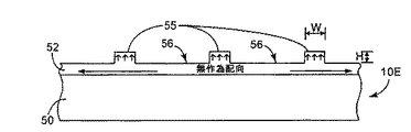
図5〜8は、本発明の実施形態によるデータ記憶媒体の例の概念的断面図である。いずれの場合も、パターン化領域55、65、75、85の少なくとも一部は、幅(W)が約5.0μm未満、より好適には約1.0μm未満である。更に、パターン化領域は、5〜100nmの範囲で高さ(H)または深さを画定することができる。
5-8 are conceptual cross-sectional views of examples of data storage media according to embodiments of the present invention. In any case, at least a portion of the patterned
図5に示すように、媒体10Eは基板50、および基板上に形成された実質的に連続している磁気記録層52を含む。記録層52は、垂直磁気異方性を顕示し、パターン化領域55および非パターン化領域56を画定する表面変型のパターンを含むように形成されている。パターン化領域55は実質的に同様に磁化することができ、非パターン化領域56は磁区が実質的に無作為な配向を示すように、実質的に非磁化されていてよい。
As shown in FIG. 5, the medium 10E includes a
図6に、図5の10E媒体と同様の媒体10Fを示す。しかし、パターン化領域65の磁化の極性は、図5に示すパターン化領域55とは反転している。上述のように、本明細書に記述する調整技術の利点の一つは、このような極性反転が容易に実行できる点である。例えば、パターン化領域を、以下に述べるヘッドの媒体上の第一のDC通過を用いて第一の方向に配向させた後で、反対極性の第二のDC通過を実行してパターン化領域を第一の方向と反対向きに配向させることができる。あるいは、以下に概説するように、ヘッドの消去通過に続いて書込み通過を用いて媒体を調整することができる。その場合、極性反転を実現するために、パターン化領域を配向させる第一の消去通過と第一の書込み通過、および第二の消去通過と第二の書き込み通過がパターン化領域を反転するように再配向させることができる。
FIG. 6 shows a medium 10F similar to the 10E medium in FIG. However, the polarity of magnetization of the patterned
更に別の実施形態において、パターン化領域は非磁化されていてよく、非パターン化領域は実質的に同じ極性により磁化することができる。このような構成は、図5、6に示すように、表面変型としてバンプよりもピットを用いる場合に特に有用である。 In yet another embodiment, the patterned region may be unmagnetized and the unpatterned region can be magnetized with substantially the same polarity. Such a configuration is particularly useful when pits are used rather than bumps as the surface deformation as shown in FIGS.
図7、8に、各々媒体10G、10Hを示し、この中でパターン化領域75、85が一つの極性に磁化されていて、非パターン化領域76、86が反対の極性に磁化されている。各々の非パターン化領域76、86に対して、パターン化領域75、85がこのように反対の極性を有していることで、個々のパターン化特徴を磁気的に検知する能力を更に強化することができる。媒体10Gまたは10Hを図7、8に示すように製造するために、以下に概要を詳述するように、追加的な調整ステップを実行することができる。
FIGS. 7 and 8 show media 10G and 10H, respectively, in which patterned
図9は、本発明の実施形態に従い、読み書きヘッド90により調整されているデータ記憶媒体10Iの例の概念的断面図である。図に示すように、ヘッド90は媒体10Iの上を通過しながら、媒体10Iの表面にDC磁場94を加える。換言すれば、直流電流(DC)をヘッド90に流して、ヘッドに非振動場94を発生させる。特に、DC磁場94の強さは、パターン化領域95を磁化させるには十分強いが、非パターン化領域96を大幅に磁化させるには弱過ぎる。ヘッド90の調整通過(横方向の矢印で示す)は、パターン化領域95が非パターン化領域96と実質的に同程度および異なる仕方で磁化されるように、パターン化領域95を調整する。しかし、DC磁場が非パターン化領域を磁化させるには十分強いが、パターン化領域を磁化させるには弱過ぎるピット形式で、同じ概念を表面変型に適用してもよい。
FIG. 9 is a conceptual cross-sectional view of an example data storage medium 10I that has been adjusted by a read /
本発明に従い、磁気記録層92は垂直磁気異方性を示すことができる。更に、ヘッド90は、米国カリフォルニア州スコッツバレー(Scotts Valley California、U.S.A)のシーゲート・テクノロジー(Seagate Technology)社から発売されているシーゲート・アポロ・サーティファイア・ヘッド(Seagate Appollo Certifier Head)等、従来型の水平読み書きヘッドを含んでいてよい。このような従来型の水平読み書きヘッドは、特徴の大きさが約5μm未満であるパターン化水平媒体の調整にはあまり効果的でないが、驚くべきことに、垂直磁気異方性を示す媒体の調整には極めて効果的である。特に、ヘッド90を用いて、パターン化領域95を磁化させるには十分であるが非パターン化領域96を磁化させるには不十分な(またはその逆)適切に選択されたDC磁場を適用することができる。パターン化領域対非パターン化領域の選択的な磁化が生じるのは、任意の時点でヘッド90の直下におけるパターン化特徴の有無により生じた、ヘッドと媒体間の間隙の微小変動に伴ない、磁束強度に相違が現れるためである。
In accordance with the present invention, the
非パターン化領域96を選択的に磁化させるために、あるいはピットの場合は非パターン化領域を選択的に磁化するために必要なDC磁場は、ヘッド90から媒体への距離だけでなく、記録層92の組成にも依存する場合がある。一例において、ヘッド90に約15mAの電流(または−15mAの電流)を流し、ヘッド90を約25nm未満のヘッド−媒体間隔で媒体10I上を通過させることにより、効果的な調整が行なわれた。この場合、ヘッド90は媒体10I上を毎分1800〜15000回転(RPM)の範囲の速度、例えば毎分約3600回転以上の速度で移動することができる。
The DC magnetic field necessary for selectively magnetizing the
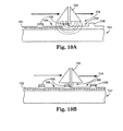
図10A、10Bは、本発明の実施形態に従い、読出し/書込みヘッド100により調整されるデータ記憶媒体10Jの例の追加的な概念的断面図である。この例で、ヘッド100は媒体10J上を少なくとも2回通過しながら、比較的強いDC磁場104を媒体10Jの表面に適用して記録層のパターン化および非パターン化領域の両方を分極化させ、次いで、パターン化領域を反対極性に磁化させるには十分強いが、非パターン化領域をその反対極性に磁化させるには弱過ぎる比較的弱いDC磁場114を適用する。ここでも、弱いDC磁場114が、非パターン化領域を磁化させるには十分強いがパターン化領域を磁化させるには弱過ぎるピット形式で、同じ概念を表面変型に適用してもよい。
10A and 10B are additional conceptual cross-sectional views of an example
ヘッド100の第一の通過(図10Aに示す)は、全ての選択的な磁化を消去して層102の垂直領域を共通の向きに配向させる消去通過と見なすことができる。ヘッド100の第二の通過(図10Bに示す)は、パターン化領域105だけ(または、図示するようにバンプではなくピットを用いる場合には非パターン化領域だけ)を磁化させる書込み通過と見なすことができる。いずれの場合も、第一の通過は層102を共通の向きに配向させ、第二の通過は非パターン化領域106から層102のパターン化領域105を磁気的に識別する。
The first pass of the head 100 (shown in FIG. 10A) can be viewed as an erase pass that erases all selective magnetization and orients the vertical regions of the
図9の例のように、図10A、10Bの例において、加えられたDC磁場は、適当な調整が行なわれるように選択することができる。例えば、図10Aに示す消去通過の間、ヘッド90に約50mAの電流(または−50mAの電流)を適用して、ヘッド90を約25nm未満のヘッド−媒体間隔、約3600RPMのヘッド速度で媒体上を通過させることにより磁場104が生じうる。図10Bに示す書込み通過の間、ヘッド90に約−15mAの電流(または15mAの電流)を適用して、ヘッド90を約25nm未満のヘッド−媒体間隔、約3600RPMのヘッド速度で媒体上を通過させることにより磁場114が生じる。重要なのは、消去通過(図10A)が正電流を使用する場合、書込み通過(図10B)は負電流を使用しなければならない点である。同様に、消去通過(図10A)が負電流を使用する場合、書込み通過(図10B)は正電流を使用しなければならない。いずれの場合も、消去通過に続いて書込み通過を用いることにより、読み戻し信号強度および磁気的に有効化された表面パターンを検知する能力の点において媒体10Jの性能が向上する。
As in the example of FIG. 9, in the example of FIGS. 10A and 10B, the applied DC magnetic field can be selected such that appropriate adjustments are made. For example, during the erase pass shown in FIG. 10A, a current of about 50 mA (or -50 mA current) is applied to the
あるいは、バルク消去プロセスはまた、消去通過の代わりに用いてもよい。換言すれば、媒体の全ての磁区を共通に配向させる強い磁場に媒体をさらすことにより消去通過と同じ効果が得られる。 Alternatively, a bulk erase process may also be used instead of an erase pass. In other words, exposing the medium to a strong magnetic field that orients all the magnetic domains of the medium in common provides the same effect as erasure passing.
本明細書に記述する技術により、パターン化領域の極性を非パターン化領域に対して容易に反転させる、またはその逆の能力を含む他のいくつかの利点を実現することができる。更に、これらの技術を用いて、書込み通過または消去通過を各々実行することにより表面パターンを磁気的にONまたはOFFに切り替えることができる。例えば、パターン化領域の選択的な磁気ON/OFF切り替えをセキュリティ目的のために用いることができる。更に、データが表面変型の形式で記録されている場合、書込み通過、または消去通過とこれに続く書込み通過を用いて、例えば媒体の損傷または消磁の後で媒体を再調整することができる。従って、本明細書に記述する技術は、効果的な再調により媒体の損傷を容易に修正できる点で記憶データの完全性を向上させることができる。 The techniques described herein can realize several other advantages, including the ability to easily reverse the polarity of the patterned region relative to the unpatterned region, or vice versa. Furthermore, using these techniques, the surface pattern can be magnetically switched on or off by executing a write pass or an erase pass, respectively. For example, selective magnetic ON / OFF switching of the patterned area can be used for security purposes. Furthermore, if the data is recorded in the form of a surface variant, the write pass or erase pass followed by the write pass can be used to readjust the media, for example after media damage or demagnetization. Thus, the techniques described herein can improve the integrity of stored data in that media damage can be easily corrected by effective retuning.
更に、本発明に従い、パターン化領域の少なくとも一部が約5.0μm未満、より好適に約1.0μm未満の幅(W)を有していてよい。パターン化領域の高さ(H)(または、突起ではなく窪を使う場合は深さ)は、5〜100nmの範囲にあってよい。特に、本明細書に記述しているように、垂直磁気異方性を示す磁気記録層を用いることで、特にパターン化領域の幅Wが約5.0μm未満、より具体的には約1.0μm未満である場合に、効果的な調整が行なわれるようにできる点が特徴であることが定められた。これらの大きさでは、水平記録層を用いた場合、本明細書に記述する調整技術は効果を発揮できない。従って、本明細書に記述しているように、垂直磁気異方性を示す記録層を用いることは、特に媒体の幅が約5.0μm未満、より具体的には約1.0μm未満である場合に、調整を容易にする有用な特徴である。 Further, in accordance with the present invention, at least a portion of the patterned region may have a width (W) of less than about 5.0 μm, more preferably less than about 1.0 μm. The height (H) of the patterned region (or depth when using a depression instead of a protrusion) may be in the range of 5-100 nm. In particular, as described herein, by using a magnetic recording layer exhibiting perpendicular magnetic anisotropy, the width W of the patterned region is less than about 5.0 μm, more specifically about 1. It was determined that the feature is that effective adjustment can be performed when the thickness is less than 0 μm. With these sizes, when the horizontal recording layer is used, the adjustment technique described in this specification cannot exhibit the effect. Therefore, as described herein, the use of a recording layer exhibiting perpendicular magnetic anisotropy particularly has a media width of less than about 5.0 μm, more specifically less than about 1.0 μm. In some cases, it is a useful feature that facilitates adjustment.
図11は、本発明の一実施形態による調整技術を示すフロー図である。図に示すように、基板または基板上に形成された層に表面変型のパターンを繰り返し、次いでこれが表面変型に実質的に合致するように磁気記録層を析出させる等により、パターン化媒体を形成する(111)。あるいは、パターン化媒体は、エッチング、エンボス加工、カレンダリング等により形成することができる。いずれの場合も、パターン化領域の幅は約5.0μm未満、より具体的には約1.0μm未満である。析出する磁気記録層は、パターン化領域の調整が確実に効果を発揮するように垂直磁気異方性を示すことができる。 FIG. 11 is a flow diagram illustrating an adjustment technique according to one embodiment of the present invention. As shown in the figure, a patterned medium is formed by repeating a surface deformation pattern on a substrate or a layer formed on the substrate, and then depositing a magnetic recording layer so that it substantially matches the surface deformation. (111). Alternatively, the patterned medium can be formed by etching, embossing, calendering, and the like. In either case, the width of the patterned region is less than about 5.0 μm, more specifically less than about 1.0 μm. The deposited magnetic recording layer can exhibit perpendicular magnetic anisotropy so that the adjustment of the patterned region is surely effective.
媒体が形成されたならば、DC磁場を媒体に適用する(113)ことにより調整することができる。例えば、図9に示すように読み出しヘッドによる一回の書込み通過を実行したり、またはより好適には図10に示すように、ヘッドの消去通過に続いて書込み通過を実行してもよい。いずれの場合も、適切に選択されたDC磁場により、パターン化領域の磁気配向を非パターン化領域の配向とは異なる仕方で行なうことができる。更に、この配向は、媒体表面にほぼ直交していて、パターン化特徴に伴なう幅が約5.0μm未満、または約1.0μm未満である場合でも効果的な調整を行なうことができる。 Once the medium is formed, it can be adjusted by applying a DC magnetic field to the medium (113). For example, a single write pass by the read head may be performed as shown in FIG. 9 or, more preferably, a write pass may be executed following the erase pass of the head, as shown in FIG. In either case, with a properly selected DC magnetic field, the magnetic orientation of the patterned region can be done differently from the orientation of the non-patterned region. In addition, this orientation can be effectively adjusted even when the width with the patterned features is less than about 5.0 μm, or less than about 1.0 μm, substantially orthogonal to the media surface.
調整されたならば、当該調整によりパターン化領域と非パターン化領域が磁気的に区別されるため、媒体は磁気ドライブ(115)を読み込むことができる。更に、例えば消磁により、媒体が後で損傷された場合(117のYES分岐)、媒体の損傷を復旧すべく再度調整を実行することができる(113)。具体的には、損傷の後でバンプまたはピットを調整して、パターンの望ましい磁気配向を復元することができる。ある場合には、磁気ドライブをプログラムして、損傷の検知に応答して調整アルゴリズムを実行するようできる。いずれの場合も、本発明は、損傷した媒体を簡単かつ効果的な仕方で調整可能にすることにより、データ完全性を向上させる。 Once adjusted, the media can be read by the magnetic drive (115) because the adjustments magnetically distinguish between the patterned and non-patterned regions. Further, if the medium is later damaged, for example, due to demagnetization (YES branch of 117), the adjustment can be performed again to recover the damage to the medium (113). Specifically, bumps or pits can be adjusted after damage to restore the desired magnetic orientation of the pattern. In some cases, the magnetic drive can be programmed to execute an adjustment algorithm in response to detection of damage. In any case, the present invention improves data integrity by allowing damaged media to be adjusted in a simple and effective manner.
本明細書に記述している技術の別の利点は、極性反転を許すことである。換言すれば、非パターン化領域に対してパターン化領域の磁化を反転させることができる。例えば、15mAのDC磁場がパターン化領域を調整すべく適用された場合、−15mAの磁場を適用することにより磁化は反転させることができる。あるいは、媒体が50mAでの消去通過および−15mAでの書込み通過の実行により調整されている場合、後で−50mAの消去通過および15mAの書込み通過を実行することにより磁化を反転させることができる。このように、媒体のパターン化特徴の極性を容易に反転させることができる。 Another advantage of the technique described herein is that it allows polarity reversal. In other words, the magnetization of the patterned region can be reversed with respect to the non-patterned region. For example, if a 15 mA DC magnetic field is applied to adjust the patterned region, the magnetization can be reversed by applying a −15 mA magnetic field. Alternatively, if the medium is tuned by performing an erase pass at 50 mA and a write pass at -15 mA, the magnetization can be reversed by performing a -50 mA erase pass and a 15 mA write pass later. In this way, the polarity of the patterned features of the medium can be easily reversed.
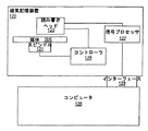
図12、13は、本明細書に記述している、媒体上のデータの読み込みまたは記録に利用できる磁気記憶装置の例のブロック図である。図12に示すように、磁気記憶装置120を、ディスク状の媒体10Kと共に用いることができる。この場合、磁気記憶装置120は、磁気ディスク・ドライブ、ハードディスク・ドライブ、フロッピーディスク・ドライブ等を含んでいてよい。磁気記録媒体10Kは基板、および基板上に形成されていて垂直磁気異方性を示す実質的に連続している磁気記録層を含んでいて、パターン化領域および非パターン化領域により画定された表面変型のパターンを示すことができる。更に、本明細書に記述するように、たとえパターン化領域が約5.0μm未満または約1.0μm未満の幅を画定する場合であっても、パターン化領域を非パターン化領域とは異なる仕方で磁化することができる。
12 and 13 are block diagrams of examples of magnetic storage devices that can be used for reading or recording data on a medium described in this specification. As shown in FIG. 12, the
スピンドル121を用いて媒体10Kを回転させることができ、読み書きヘッド123を媒体10K上の磁区を検知するように配置することができる。コントローラ125は、スピンドル121および読み書きヘッド123を制御して、読み書きヘッド123を媒体10Kに対して正確に位置付ける。信号プロセッサ127は、検知された磁区を解釈する。ある場合には、本明細書に記述しているように、コントローラ125は読み書きヘッド123に対して媒体10Kの調整を実行するよう指示する。
The
磁気記憶装置120は、インターフェース129を介してコンピュータ128に接続することができる。コンピュータ128は例えば、PC、マッキントッシュ、コンピュータ・ワークステーション、携帯データ端子、パーム・コンピュータ、携帯電話、デジタル用紙、デジタル・テレビ、無線デバイス(その場合インターフェース129は無線でありうる)、携帯情報端末、ラップトップ・コンピュータ、デスクトップ・コンピュータ、デジタル・カメラ、デジタル記録装置等、多岐にわたる任意のコンピュータ装置用の中央演算処理装置を含んでいてよい。
The
図13に示すように、磁気記憶装置130は、磁気テープを含む媒体10Lと共に用いてもよい。その場合、磁気記憶装置130は、磁気テープ・ドライブ、磁気テープ・カートリッジ・ドライブ等を含んでいてよい。媒体10Lは、1個以上のスプール131A、131B上へスプールされる磁気テープを含んでいてよい。スプール131はカートリッジに収納することができるが、本発明はこの点に限定されない。磁気テープ形式である磁気記録媒体10Lは基板、および基板上に形成されていて、垂直磁気異方性を示す実質的に連続している磁気記録層を含み、パターン化領域および非パターン化領域により画定された表面変型のパターンを示すことができる。更に、本明細書に記述しているように、たとえパターン化領域が約5.0μm未満または約1.0μm未満の幅を画定する場合でも、パターン化領域は非パターン化領域とは異なる仕方で磁化することができる。
As shown in FIG. 13, the
読み書きヘッド133は、媒体10L上の磁区を検知すべく配置することができる。コントローラ135は、媒体10Lの動きだけでなく読み書きヘッド133の配置も制御して、スプール133Aおよび/または133Bを回転させて読み書きヘッド133を媒体10Lに対して正確に位置付けるようにする。信号プロセッサ137は、検知された磁区を解釈する。ある場合には、本明細書に記述しているように、コントローラ135は読み書きヘッド133に媒体10Lの調整を実行させる。
The read /
図12と同様に、図13の磁気記憶装置130はインターフェース139を介してコンピュータ138に接続することができる。ここでも、コンピュータ138は例えば、PC、マッキントッシュ、コンピュータ・ワークステーション、携帯データ端子、パーム・コンピュータ、携帯電話、デジタル用紙、デジタル・テレビ、無線デバイス、携帯情報端末、ラップトップ・コンピュータ、デスクトップ・コンピュータ、デジタル・カメラ、デジタル記録装置等、多岐にわたる任意のコンピュータ装置向けの中央演算処理装置を含んでいてよい。
Similar to FIG. 12, the
本発明は、多くの利点をもたらすことができる。特に、本発明による垂直磁気媒体は、従来の水平媒体よりも高い記憶密度を実現することができる。垂直磁気異方性を示す磁気記録層の利用することは、本明細書に記述しているように、特にパターン化領域の幅Wが約5.0μm未満、より具体的には約1.0μm未満である場合に、効果的な調整が行なえることを可能にする特徴である。この辺りの大きさでは、水平記録層を用いた場合、調整技術の効果が小さいか、無効である恐れがある。従って、本明細書に記述しているように、垂直磁気異方性を示す記録層を用いることは、特に媒体の幅が約5.0μm未満、より具体的には約1.0μm未満である場合に、調整を容易にする有用な特徴である。 The present invention can provide a number of advantages. In particular, the perpendicular magnetic medium according to the present invention can realize a higher storage density than a conventional horizontal medium. The use of a magnetic recording layer exhibiting perpendicular magnetic anisotropy, as described herein, is particularly that the width W of the patterned region is less than about 5.0 μm, more specifically about 1.0 μm. This is a feature that makes it possible to perform effective adjustment when the value is less than. At this size, when the horizontal recording layer is used, there is a possibility that the effect of the adjustment technique is small or invalid. Therefore, as described herein, the use of a recording layer exhibiting perpendicular magnetic anisotropy particularly has a media width of less than about 5.0 μm, more specifically less than about 1.0 μm. In some cases, it is a useful feature that facilitates adjustment.
これらのおよび他の実施形態も添付の特許請求の範囲に含まれる。 These and other embodiments are within the scope of the appended claims.
10 磁気記録媒体、12 表面変形、20 基板、22 磁気記録層、25 パターン化領域、26 非パターン化領域、32 磁気記録層、35 パターン化領域、36 非パターン化領域、40 基板、45 パターン化領域、46 非パターン化領域、47 特徴。
10 magnetic recording medium, 12 surface deformation, 20 substrate, 22 magnetic recording layer, 25 patterned region, 26 non-patterned region, 32 magnetic recording layer, 35 patterned region, 36 non-patterned region, 40 substrate, 45 patterned Region, 46 unpatterned region, 47 features.
Claims (15)
基板と、
前記基板上に形成された垂直磁気異方性を示す磁気記録層であって、パターン化領域および非パターン化領域により画定された表面変型のパターンを含む磁気記録層とを含み、前記パターン化領域が前記非パターン化領域とは異なる仕方で磁化されている媒体。 A magnetic recording medium,
A substrate,
A magnetic recording layer having perpendicular magnetic anisotropy formed on the substrate, the magnetic recording layer including a surface deformation pattern defined by a patterned region and a non-patterned region, and the patterned region Is magnetized in a different manner than the unpatterned region.
第一のDC磁場を前記媒体に適用して、前記パターン化領域および前記非パターン化領域を同様に磁化させるステップと、
第二のDC磁場を前記媒体に適用して、前記パターン化領域を前記非パターン化領域とは異なる仕方で磁化させるステップとを含む方法。 In the step of receiving a patterned magnetic medium having perpendicular magnetic anisotropy to show a pattern of surface deformation defined by the patterned and non-patterned regions, at least a portion of the patterned region has a width of about 5 Defining a width of less than 0.0 μm;
Applying a first DC magnetic field to the medium to similarly magnetize the patterned and non-patterned regions;
Applying a second DC magnetic field to the medium to magnetize the patterned region differently than the non-patterned region.
前記媒体に前記第一のDC磁場を再適用して前記パターン化領域と前記非パターン化領域を同様に磁化させることにより、および前記媒体に第二のDC磁場を再適用して前記パターン化領域を前記非パターン化領域とは異なる仕方で磁化させることにより、前記媒体を損傷させないステップとを更に含む、請求項11に記載の方法。 Receiving the patterned magnetic medium in a damaged state;
Re-applying the first DC magnetic field to the medium to similarly magnetize the patterned region and the non-patterned region, and re-applying a second DC magnetic field to the medium to form the patterned region The method of claim 11, further comprising: magnetizing the medium in a different manner than the non-patterned region so as not to damage the medium.
磁気記録媒体と、
前記媒体上の磁区を検知するヘッドと、
前記媒体に対する前記ヘッドの位置を制御するコントローラと、
検知された磁区を解釈する信号プロセッサとを含み、
前記磁気記録媒体が基板と、パターン化領域および非パターン化領域により画定された表面変型のパターンを示すように前記基板上に形成された垂直磁気異方性を示す、実質的に連続している磁気記録層とを含み、前記パターン化領域が前記非パターン化領域とは異なる仕方で磁化されている装置。 A magnetic storage device,
A magnetic recording medium;
A head for detecting a magnetic domain on the medium;
A controller for controlling the position of the head relative to the medium;
A signal processor for interpreting the detected magnetic domains,
The magnetic recording medium is substantially continuous exhibiting perpendicular magnetic anisotropy formed on the substrate to exhibit a surface-modified pattern defined by the substrate and patterned and non-patterned regions. A magnetic recording layer, wherein the patterned region is magnetized differently from the non-patterned region.
The patterned region is magnetized with a first polarity, the non-patterned region is magnetized with a second polarity, and the second polarity is opposite the first polarity. 2. A perpendicular magnetic recording medium according to 1.
Applications Claiming Priority (2)
| Application Number | Priority Date | Filing Date | Title |
|---|---|---|---|
| US10/283,401 US6999279B2 (en) | 2002-10-29 | 2002-10-29 | Perpendicular patterned magnetic media |
| PCT/US2003/032594 WO2004040559A2 (en) | 2002-10-29 | 2003-10-16 | Perpendicular patterned magnetic media |
Publications (2)
| Publication Number | Publication Date |
|---|---|
| JP2006505091A true JP2006505091A (en) | 2006-02-09 |
| JP2006505091A5 JP2006505091A5 (en) | 2006-11-30 |
Family
ID=32107516
Family Applications (1)
| Application Number | Title | Priority Date | Filing Date |
|---|---|---|---|
| JP2004548381A Pending JP2006505091A (en) | 2002-10-29 | 2003-10-16 | Vertical patterned magnetic media |
Country Status (6)
| Country | Link |
|---|---|
| US (1) | US6999279B2 (en) |
| JP (1) | JP2006505091A (en) |
| CN (1) | CN1708788A (en) |
| AU (1) | AU2003277386A1 (en) |
| DE (1) | DE10393593T5 (en) |
| WO (1) | WO2004040559A2 (en) |
Families Citing this family (37)
| Publication number | Priority date | Publication date | Assignee | Title |
|---|---|---|---|---|
| US7019924B2 (en) | 2001-02-16 | 2006-03-28 | Komag, Incorporated | Patterned medium and recording head |
| US7147790B2 (en) * | 2002-11-27 | 2006-12-12 | Komag, Inc. | Perpendicular magnetic discrete track recording disk |
| US20050036223A1 (en) * | 2002-11-27 | 2005-02-17 | Wachenschwanz David E. | Magnetic discrete track recording disk |
| US6947235B2 (en) * | 2003-12-03 | 2005-09-20 | Hitachi Global Storage Technologies Netherlands B.V. | Patterned multilevel perpendicular magnetic recording media |
| JP2006031856A (en) * | 2004-07-16 | 2006-02-02 | Toshiba Corp | Patterned disk medium for vertical magnetic recording, and magnetic disk drive mounting medium thereon |
| DE102005022473B4 (en) * | 2005-05-14 | 2007-05-24 | Forschungszentrum Karlsruhe Gmbh | Device for damping reflections of electromagnetic waves, process for their preparation and their use |
| JP4675722B2 (en) * | 2005-09-02 | 2011-04-27 | 株式会社東芝 | Magnetic recording medium |
| DE202006000083U1 (en) | 2006-01-03 | 2007-02-08 | Monolith GmbH Bürosysteme | Binding system for binding sheet material |
| US8900655B2 (en) | 2006-10-04 | 2014-12-02 | Seagate Technology Llc | Method for fabricating patterned magnetic recording device |
| US7704614B2 (en) * | 2006-10-20 | 2010-04-27 | Seagate Technology Llc | Process for fabricating patterned magnetic recording media |
| US7532422B2 (en) * | 2006-10-25 | 2009-05-12 | Mra Tek, Llc | Method and system for distinguishing spatial and thermal defects on perpendicular media |
| JP2008152903A (en) * | 2006-11-21 | 2008-07-03 | Toshiba Corp | Magnetic recording medium, method for manufacturing the same, and magnetic recording apparatus |
| US7919029B2 (en) * | 2006-12-01 | 2011-04-05 | Seagate Technology Llc | Thermal compensated stampers/imprinters |
| JP4296204B2 (en) * | 2007-03-26 | 2009-07-15 | 株式会社東芝 | Magnetic recording medium |
| JP4703604B2 (en) * | 2007-05-23 | 2011-06-15 | 株式会社東芝 | Magnetic recording medium and method for manufacturing the same |
| US7835099B2 (en) | 2007-06-29 | 2010-11-16 | Seagate Technology Llc | Method and system for error checking in a bit-patterned media |
| JP4382843B2 (en) * | 2007-09-26 | 2009-12-16 | 株式会社東芝 | Magnetic recording medium and method for manufacturing the same |
| US7864470B2 (en) * | 2007-10-11 | 2011-01-04 | Seagate Technology Llc | Patterned media with spacings adjusted by a skew function |
| DE202008000878U1 (en) | 2008-01-21 | 2008-03-20 | Purple Cows Gmbh | Bindering for binding sheet material |
| US7835094B2 (en) * | 2008-07-02 | 2010-11-16 | Seagate Technology Llc | Embedded track information for patterned media |
| US7920354B2 (en) * | 2008-09-15 | 2011-04-05 | Seagate Technology Llc | Phase servo patterns for bit patterned media |
| US8947809B2 (en) * | 2008-09-19 | 2015-02-03 | Seagate Technology Llc | Encoding scheme for bit patterned media |
| US8824079B2 (en) * | 2008-09-15 | 2014-09-02 | Seagate Technology Llc | Servo patterns for bit patterned media with multiple dots per servo period |
| US8339722B1 (en) * | 2008-11-17 | 2012-12-25 | Marvell International Ltd. | Methods of demodulating a servo positon error signal on patterned media |
| JP2010134977A (en) * | 2008-12-02 | 2010-06-17 | Toshiba Storage Device Corp | Magnetic recording medium and magnetic storage device |
| US9111565B2 (en) * | 2009-01-16 | 2015-08-18 | Seagate Technology Llc | Data storage device with both bit patterned and continuous media |
| US7960044B2 (en) * | 2009-03-27 | 2011-06-14 | Hitachi Global Storage Technologies Netherlands B.V. | Patterned-media perpendicular magnetic recording disk with servo regions having magnetized servo pillars and oppositely-magnetized servo trenches |
| US8804276B2 (en) | 2011-06-13 | 2014-08-12 | Imation Corp. | Continuous biasing and servowriting of magnetic storage media having perpendicular anisotropy |
| US8797674B2 (en) | 2011-06-13 | 2014-08-05 | Imation Corp. | Servo mark length matched to write head gap for magnetic storage media |
| US8817415B2 (en) * | 2011-06-13 | 2014-08-26 | Imation Corp. | Erasure of magnetic storage media having perpendicular anisotropy |
| US8767342B2 (en) | 2011-06-13 | 2014-07-01 | Imation Corp. | Erasure and servowriting of magnetic storage media having perpendicular anistropy |
| US8867157B2 (en) | 2012-04-04 | 2014-10-21 | Imation Corp. | Perpendicular pole head for servo writing magnetic media |
| US9147423B2 (en) | 2012-04-17 | 2015-09-29 | HGST Netherlands B.V. | Method for improving a patterned perpendicular magnetic recording disk with annealing |
| US8643968B2 (en) | 2012-04-26 | 2014-02-04 | Imation Corp. | Methods and systems for magnetic media servo writing |
| US8760802B2 (en) | 2012-04-26 | 2014-06-24 | Imation Corp. | Systems and methods for processing magnetic media with first and second magnetic gaps adjacent opposite sides of the recording layer |
| US8867167B2 (en) | 2012-04-26 | 2014-10-21 | Imation Corp. | Tapered pole heads for magnetic media |
| US8797681B2 (en) | 2012-04-26 | 2014-08-05 | Imation Corp. | Servo write head having plural spaced front blocks coupled by magnetic posts to a back bar |
Family Cites Families (17)
| Publication number | Priority date | Publication date | Assignee | Title |
|---|---|---|---|---|
| JPS5963005A (en) * | 1982-10-04 | 1984-04-10 | Toshiba Corp | Magnetic recording system |
| US4656546A (en) * | 1985-01-22 | 1987-04-07 | Digital Equipment Corporation | Vertical magnetic recording arrangement |
| JP3254743B2 (en) | 1992-08-17 | 2002-02-12 | ソニー株式会社 | Writing method of positioning signal |
| JP3344495B2 (en) | 1993-03-04 | 2002-11-11 | ソニー株式会社 | Magnetic disk drive |
| JP3271406B2 (en) | 1993-11-30 | 2002-04-02 | ソニー株式会社 | Perpendicular magnetic recording medium and signal recording method for the perpendicular magnetic recording medium |
| US5537282A (en) | 1994-07-15 | 1996-07-16 | Treves; David | Data storage disk having improved tracking capability |
| US5723033A (en) | 1995-09-06 | 1998-03-03 | Akashic Memories Corporation | Discrete track media produced by underlayer laser ablation |
| US5991104A (en) | 1996-11-27 | 1999-11-23 | Seagate Technology, Inc. | Using servowriter medium for quickly written servo-patterns on magnetic media |
| WO1999040575A1 (en) | 1998-02-10 | 1999-08-12 | Seagate Technology Llc | Magnetic recording medium with patterned substrate |
| JPH11296845A (en) | 1998-04-14 | 1999-10-29 | Tdk Corp | Magnetic disk medium and magnetic recording device |
| US6168845B1 (en) | 1999-01-19 | 2001-01-02 | International Business Machines Corporation | Patterned magnetic media and method of making the same using selective oxidation |
| JP2000306236A (en) | 1999-04-22 | 2000-11-02 | Sony Corp | Device and method for magnetization |
| US6421195B1 (en) | 1999-09-20 | 2002-07-16 | International Business Machines Corporation | Magnetic disk media with patterned sections |
| US6383597B1 (en) | 2000-06-21 | 2002-05-07 | International Business Machines Corporation | Magnetic recording media with magnetic bit regions patterned by ion irradiation |
| US6391430B1 (en) | 2000-06-21 | 2002-05-21 | International Business Machines Corporation | Patterned magnetic recording media with discrete magnetic regions separated by regions of antiferromagnetically coupled films |
| WO2002023538A2 (en) | 2000-09-12 | 2002-03-21 | Seagate Technology Llc | Method and apparatus for minimizing slider fly heights over patterned media |
| US6657809B2 (en) | 2001-01-29 | 2003-12-02 | International Business Machines Corporation | Method and apparatus for positioning a transducer using a phase difference in surface profile variations on a storage medium |
-
2002
- 2002-10-29 US US10/283,401 patent/US6999279B2/en not_active Expired - Lifetime
-
2003
- 2003-10-16 AU AU2003277386A patent/AU2003277386A1/en not_active Abandoned
- 2003-10-16 CN CNA2003801025218A patent/CN1708788A/en active Pending
- 2003-10-16 JP JP2004548381A patent/JP2006505091A/en active Pending
- 2003-10-16 WO PCT/US2003/032594 patent/WO2004040559A2/en active Application Filing
- 2003-10-16 DE DE10393593T patent/DE10393593T5/en not_active Withdrawn
Also Published As
| Publication number | Publication date |
|---|---|
| CN1708788A (en) | 2005-12-14 |
| DE10393593T5 (en) | 2005-09-29 |
| WO2004040559A2 (en) | 2004-05-13 |
| AU2003277386A1 (en) | 2004-05-25 |
| US20040080847A1 (en) | 2004-04-29 |
| US6999279B2 (en) | 2006-02-14 |
| WO2004040559A3 (en) | 2004-09-02 |
Similar Documents
| Publication | Publication Date | Title |
|---|---|---|
| JP2006505091A (en) | Vertical patterned magnetic media | |
| US5991104A (en) | Using servowriter medium for quickly written servo-patterns on magnetic media | |
| US6153281A (en) | Magnetic media with permanently defined non-magnetic tracks and servo-patterns | |
| US6086961A (en) | Quickly written servo-patterns for magnetic media including removing | |
| JP3816911B2 (en) | Magnetic recording medium | |
| US8797674B2 (en) | Servo mark length matched to write head gap for magnetic storage media | |
| US7050251B2 (en) | Encoding techniques for patterned magnetic media | |
| US7218465B1 (en) | Magnetic media patterning via contact printing utilizing stamper having magnetic pattern formed in non-magnetic substrate | |
| US20020071214A1 (en) | Perpendicular magnetic recording media with patterned soft magnetic underlayer | |
| JP3884394B2 (en) | Recording medium, recording / reproducing apparatus, recording medium manufacturing apparatus, and recording medium manufacturing method | |
| JP4031456B2 (en) | Magnetic recording medium and magnetic storage medium manufacturing method | |
| US8817415B2 (en) | Erasure of magnetic storage media having perpendicular anisotropy | |
| US7885026B2 (en) | Magnetic recording medium and method of fabricating the same | |
| US6351339B1 (en) | Multi-dimensionally oriented magnetic field information storage system | |
| US6761618B1 (en) | Defect-free magnetic stampers/imprinters for contact patterning of magnetic media | |
| US20100053809A1 (en) | Embedded servo on track for bit-patterned media (bpm) | |
| JP4517329B2 (en) | Perpendicular magnetic recording medium | |
| JP5259645B2 (en) | Magnetic recording medium and method for manufacturing the same | |
| JP2010257555A (en) | Magnetic recording medium, information storage device and method for producing magnetic recording medium | |
| US9177598B2 (en) | Device, method of fabricating a media and method of servo writing | |
| WO2000026904A1 (en) | Master information medium and method of master information recording | |
| US7170699B2 (en) | Master disk having grooves of different depths for magnetic printing and manufacturing method therefor | |
| US20090316297A1 (en) | Servo master and magnetic transfer method using the same | |
| Arellano et al. | Bit-Patterned Media on Plastic Tape With Feature Density of 100 Gigadot/in $^{{2}} $ | |
| US20040209185A1 (en) | Contact printing of longitudinal magnetic media with perpendicularly applied magnetic field |
Legal Events
| Date | Code | Title | Description |
|---|---|---|---|
| A521 | Request for written amendment filed |
Free format text: JAPANESE INTERMEDIATE CODE: A523 Effective date: 20061011 |
|
| A621 | Written request for application examination |
Free format text: JAPANESE INTERMEDIATE CODE: A621 Effective date: 20061011 |
|
| RD02 | Notification of acceptance of power of attorney |
Free format text: JAPANESE INTERMEDIATE CODE: A7422 Effective date: 20061011 |
|
| A977 | Report on retrieval |
Free format text: JAPANESE INTERMEDIATE CODE: A971007 Effective date: 20070730 |
|
| A131 | Notification of reasons for refusal |
Free format text: JAPANESE INTERMEDIATE CODE: A131 Effective date: 20070814 |
|
| A601 | Written request for extension of time |
Free format text: JAPANESE INTERMEDIATE CODE: A601 Effective date: 20071114 |
|
| A602 | Written permission of extension of time |
Free format text: JAPANESE INTERMEDIATE CODE: A602 Effective date: 20071121 |
|
| A521 | Request for written amendment filed |
Free format text: JAPANESE INTERMEDIATE CODE: A523 Effective date: 20071214 |
|
| A02 | Decision of refusal |
Free format text: JAPANESE INTERMEDIATE CODE: A02 Effective date: 20080129 |