JP2006500108A - Microcoil vascular occlusion device with multi-axis secondary shape - Google Patents
Microcoil vascular occlusion device with multi-axis secondary shape Download PDFInfo
- Publication number
- JP2006500108A JP2006500108A JP2004537987A JP2004537987A JP2006500108A JP 2006500108 A JP2006500108 A JP 2006500108A JP 2004537987 A JP2004537987 A JP 2004537987A JP 2004537987 A JP2004537987 A JP 2004537987A JP 2006500108 A JP2006500108 A JP 2006500108A
- Authority
- JP
- Japan
- Prior art keywords
- energy state
- vaso
- lowest energy
- vascular site
- secondary shape
- Prior art date
- Legal status (The legal status is an assumption and is not a legal conclusion. Google has not performed a legal analysis and makes no representation as to the accuracy of the status listed.)
- Pending
Links
Images


Classifications
-
- A—HUMAN NECESSITIES
- A61—MEDICAL OR VETERINARY SCIENCE; HYGIENE
- A61B—DIAGNOSIS; SURGERY; IDENTIFICATION
- A61B17/00—Surgical instruments, devices or methods, e.g. tourniquets
- A61B17/12—Surgical instruments, devices or methods, e.g. tourniquets for ligaturing or otherwise compressing tubular parts of the body, e.g. blood vessels, umbilical cord
- A61B17/12022—Occluding by internal devices, e.g. balloons or releasable wires
- A61B17/12099—Occluding by internal devices, e.g. balloons or releasable wires characterised by the location of the occluder
- A61B17/12109—Occluding by internal devices, e.g. balloons or releasable wires characterised by the location of the occluder in a blood vessel
- A61B17/12113—Occluding by internal devices, e.g. balloons or releasable wires characterised by the location of the occluder in a blood vessel within an aneurysm
-
- A—HUMAN NECESSITIES
- A61—MEDICAL OR VETERINARY SCIENCE; HYGIENE
- A61B—DIAGNOSIS; SURGERY; IDENTIFICATION
- A61B17/00—Surgical instruments, devices or methods, e.g. tourniquets
- A61B17/12—Surgical instruments, devices or methods, e.g. tourniquets for ligaturing or otherwise compressing tubular parts of the body, e.g. blood vessels, umbilical cord
- A61B17/12022—Occluding by internal devices, e.g. balloons or releasable wires
- A61B17/12131—Occluding by internal devices, e.g. balloons or releasable wires characterised by the type of occluding device
- A61B17/1214—Coils or wires
- A61B17/12145—Coils or wires having a pre-set deployed three-dimensional shape
-
- A—HUMAN NECESSITIES
- A61—MEDICAL OR VETERINARY SCIENCE; HYGIENE
- A61B—DIAGNOSIS; SURGERY; IDENTIFICATION
- A61B17/00—Surgical instruments, devices or methods, e.g. tourniquets
- A61B2017/00831—Material properties
- A61B2017/00867—Material properties shape memory effect
Landscapes
- Health & Medical Sciences (AREA)
- Surgery (AREA)
- Life Sciences & Earth Sciences (AREA)
- Heart & Thoracic Surgery (AREA)
- Molecular Biology (AREA)
- Vascular Medicine (AREA)
- Engineering & Computer Science (AREA)
- Biomedical Technology (AREA)
- Reproductive Health (AREA)
- Medical Informatics (AREA)
- Nuclear Medicine, Radiotherapy & Molecular Imaging (AREA)
- Animal Behavior & Ethology (AREA)
- General Health & Medical Sciences (AREA)
- Public Health (AREA)
- Veterinary Medicine (AREA)
- Neurosurgery (AREA)
- Surgical Instruments (AREA)
Abstract
脈管閉塞デバイスは、複数の湾曲セグメントを備える二次形状へと形成されるマイクロコイルを含む。二次形状は、複数の相互接続する閉ループ又は横方向に交互に開放するループを備え得る。これらループは複数の別個の軸線を規定する。あるいは、二次形状は、全体構成が第1角度の範囲で、かつ隣り合うループの各組が第2角度を規定する一連の閉ループを形成するか、又は対数螺旋を形成し得る。本デバイスは、その二次形状において、該デバイスが配置される動脈瘤の最大寸法よりも大きい寸法を有する。従って、本デバイスの動脈瘤内への閉じ込めは、該デバイスに、二次形状の最低エネルギー状態よりも高いエネルギー状態の形状を帯びさせる。最低エネルギー状態形状が動脈瘤よりも大きいので(少なくとも一の次元において)、配置されたデバイスは、その最低エネルギー状態形状に戻らないように動脈瘤により拘束され、また、該デバイスの閉じ込めは、血流による該デバイスの移動を最小にする。The vaso-occlusive device includes a microcoil formed into a secondary shape with a plurality of curved segments. The secondary shape may comprise a plurality of interconnected closed loops or laterally open loops. These loops define a plurality of distinct axes. Alternatively, the secondary shape may form a series of closed loops where the overall configuration is in the first angle range and each set of adjacent loops defines a second angle, or a logarithmic helix. The device has a dimension in its secondary shape that is greater than the largest dimension of the aneurysm in which the device is placed. Thus, confinement of the device within the aneurysm causes the device to assume a shape of an energy state that is higher than the lowest energy state of the secondary shape. Because the lowest energy state shape is larger than the aneurysm (in at least one dimension), the deployed device is constrained by the aneurysm so that it does not return to its lowest energy state shape, and the confinement of the device is blood Minimize movement of the device by flow.
Description
本発明は、一般に脈管閉塞の装置(デバイス)及び方法の分野に関連する。更に詳しくは、本発明は、血管中の(動脈瘤といった)標的部位を閉鎖することにより、血管を塞ぐための装置及び方法に関する。 The present invention relates generally to the field of vessel occlusion devices and methods. More particularly, the present invention relates to an apparatus and method for closing a blood vessel by closing a target site (such as an aneurysm) in the blood vessel.
血管の塞栓形成法(塞栓術)は、多くの臨床状況において望まれる。例えば、脈管栓塞形成法は、脈管出血を制御したり、腫瘍への血液供給を防いだり、血管動脈瘤、特に頭蓋内動脈瘤を塞ぐために用いられている。近年、動脈瘤の治療のための血管塞栓形成法が多くの注目を浴びている。いくつかの異なる治療の物理療法が先行技術において用いられている。例えば、Dormandy, Jr.等の米国特許第4,819,637号は、血管内カテーテルによって動脈瘤部位まで運ばれる取り外し可能なバルーンを使用する血管塞栓形成システムを記載している。該バルーンは、カテーテルの先端にて動脈瘤内へ搬入され、該動脈瘤内で凝固液(一般に重合可能な樹脂又はゲル)で膨らまされて該動脈瘤を塞ぐ。該バルーンは、次に、カテーテルの優しい牽引によってカテーテルから取り外される。該バルーン型栓塞形成装置は、多様な動脈瘤の効果的な閉塞を与えることができるが、凝固液のセット後に取り出すこと又は移動させることが難しく、また、それが造影剤で満たされない限り、視覚化(映像化)は困難である。更に、膨張時にバルーンが破裂する危険性、及びカテーテルからのバルーンの取り外しが早すぎる危険性がある。 Vascular embolization (embolization) is desirable in many clinical situations. For example, vascular embolization is used to control vascular bleeding, prevent blood supply to the tumor, and occlude vascular aneurysms, particularly intracranial aneurysms. In recent years, vascular embolization for the treatment of aneurysms has received much attention. Several different therapeutic physical therapies are used in the prior art. For example, Dormandy, Jr. U.S. Pat. No. 4,819,637 describes a vascular embolization system that uses a removable balloon that is carried by an intravascular catheter to the aneurysm site. The balloon is carried into the aneurysm at the distal end of the catheter, and inflated with a coagulation liquid (generally a polymerizable resin or gel) in the aneurysm to close the aneurysm. The balloon is then removed from the catheter by gentle traction of the catheter. The balloon embolization device can provide effective occlusion of a variety of aneurysms, but is difficult to remove or move after setting of the coagulant and is visually invisible unless it is filled with contrast agent. (Visualization) is difficult. In addition, there is a risk of the balloon rupturing when inflated and the risk of removing the balloon from the catheter too early.
別のアプローチは、塞がれる脈管部位への液体ポリマー塞栓性剤の直接注入である。該直接注入技術に用いられる液体ポリマーの一タイプは、シアノアクリレート樹脂、特にイソブチルシアノアクリレートのような急速重合液であり、これは、液体として標的部位へと送られ、次いで、その部位で重合する。あるいは、標的部位で担体溶液から沈殿させられる液体ポリマーが用いられている。このタイプの栓塞性剤の例は、三酸化ビスマスと混合され、かつジメチルスルホキシド(DMSO)に溶解された酢酸セルロース重合体である。別のタイプは、DMSOに溶解されたエチレングリコール共重合体である。血液と接触すると、該DMSOは拡散し、また、該重合体が析出し、急速に固まって、動脈瘤の形状に一致する栓塞塊となる。この「直接注入」法に用いられる物質の他の例は、次の米国特許、すなわちPasztor等の第4,551,132号、Leshchiner等の4,795,741号、Ito等の5,525,334号及びGreff等の5,580,568号に開示される。 Another approach is the direct injection of a liquid polymer embolic agent into the vascular site to be occluded. One type of liquid polymer used in the direct injection technique is a rapid polymerization liquid such as a cyanoacrylate resin, especially isobutyl cyanoacrylate, which is sent as a liquid to a target site and then polymerizes at that site. . Alternatively, a liquid polymer is used that is precipitated from the carrier solution at the target site. An example of this type of embolic agent is a cellulose acetate polymer mixed with bismuth trioxide and dissolved in dimethyl sulfoxide (DMSO). Another type is an ethylene glycol copolymer dissolved in DMSO. Upon contact with blood, the DMSO diffuses and the polymer precipitates and rapidly solidifies into an embolus that conforms to the shape of the aneurysm. Other examples of materials used in this “direct injection” method include the following US patents: Pasztor et al. 4,551,132, Leshchiner et al. 4,795,741, Ito et al. 5,525, 334 and Greff et al., 5,580,568.
液体ポリマー塞栓性剤の直接注入は、実際には難しいことが実証されている。例えば、高分子材料の動脈瘤から隣接した血管への移動が問題を提起している。加えて、栓塞形成物質の視覚化は、造影剤が該物質と混合させられることを必要とし、相互に適合する(相性が良い)栓塞形成物質及び造影剤の選定は、最適未満の性能妥協点をもたらすであろう。更に、高分子栓塞形成物質の配置の正確な制御が難しく、該物質の不適当な配置及び/又は早すぎる凝固の危険性をまねく。更には、一旦該栓塞形成物質が配置され凝固すると、移動又は回収は困難である。 Direct injection of liquid polymer embolic agents has proven difficult in practice. For example, migration of polymeric material from an aneurysm to an adjacent blood vessel presents a problem. In addition, the visualization of the embolizing material requires that the contrast agent be mixed with the material, and the selection of a compatible (and compatible) embolizing material and contrast agent is a suboptimal performance compromise Will bring. Furthermore, precise control of the placement of the polymeric embolization material is difficult, leading to improper placement of the material and / or risk of premature clotting. Furthermore, once the embolization material is placed and solidified, it is difficult to move or recover.
有望な別のアプローチは、トロンボゲン(血栓)形成のマイクロコイルを使用することである。これらマイクロコイルは、生物学的適合性金属合金(典型的には白金及びタングステン)又は適当な重合体から製造され得る。金属からなる場合、上記コイルには、血栓形成性を高めるため、ダクロン(「登録商標」)繊維が与えられ得る。該コイルは、マイクロカテーテルを通じて脈管部位へと配置される。マイクロコイルの例は、以下の米国特許に開示される。すなわち、Ritchart等の第4,994,069号、Guglielmi等の第5,122,136号、Butler等の第5,133,731号、Chee等の第5,226,911号、Chee等の第5,304,194号、Palermoの5,312,415号、Phelps等の第5,382,259号、Dormandy, Jr.等の第5,382,260号、Dormandy, Jr.第5,476,472号、Mirigianの第5,578,074号、Kenの第5,582,619号、Mariantの第5,624,461号、Mariant等の第5,639,277号、Snyderの第5,658,308号、Giaの第5,690,667号、McGurk等の第5,690,671号、Mirigian等の第5,700,258号、Berenstein等の第5,718,711号、Taki等の第5,891,058号、Ken等の第6,013,084号、Rosenbluth等の第6,015,424号、及び、Mariant等のデザイン特許第427,680号である。 Another promising approach is to use thrombogenic (thrombus) -forming microcoils. These microcoils can be made from a biocompatible metal alloy (typically platinum and tungsten) or a suitable polymer. When made of metal, the coil may be provided with Dacron (“registered trademark”) fibers to enhance thrombus formation. The coil is placed through the microcatheter and into the vascular site. Examples of microcoils are disclosed in the following US patents. Ritchart et al. 4,994,069, Guglielmi et al. 5,122,136, Butler et al. 5,133,731, Chee et al. 5,226,911, Chee et al. No. 5,304,194, Palermo No. 5,312,415, Phelps et al. No. 5,382,259, Dormandy, Jr. No. 5,382,260, Dormandy, Jr. et al. 5,476,472, Mirigian 5,578,074, Ken 5,582,619, Mariant 5,624,461, Mariant et al 5,639,277, Snyder No. 5,658,308, Gia No. 5,690,667, McGurk et al. 5,690,671, Mirigian et al. 5,700,258, Berenstein et al. 5,718,711 No. 5, Taki et al. 5,891,058, Ken et al. 6,013,084, Rosenbluth et al. 6,015,424, and Mariant et al. Design Patent No. 427,680.
多くの先行技術のマイクロコイル装置(デバイス)は、頸部(くびれの部分)が比較的細い小さい動脈瘤の処置においてはある程度成功したが、最も一般的に使用される脈管閉塞装置マイクロコイルは、頸部が広い動脈瘤、特に大脳において満足のいかない結果を出していることが認識されている。これは、Hortonの米国特許第5,645,558号、Pham等の同第5,911,731号及びMariantの同第5,957,948号に開示されるような三次元マイクロコイル装置の開発へと至った(後二者は、「三次元グリエルミ離脱型(着脱可能)コイル」又は「3D−GDC」として知られている装置に分類される。)。例えば、Tan等の「The Feasibility of Three-Dimensional Guglielmi Detachable Coil for Embolisation of Wide Neck Cerebral Aneurysms」、Interventional Neuroradiology、第6巻、53−57頁(2000年6月)、Cloft等の「Use of Three-Dimensional Guglielmi Detachable Coils in the Treatment of Wide-necked Cerebral Aneurysms」、American Journal of Neuroradiology、第21巻、1312−1314頁(2000年8月)参照。 Although many prior art microcoil devices (devices) have had some success in treating small aneurysms with a relatively narrow neck (constriction), the most commonly used vaso-occlusive device microcoils are It has been recognized that uncertain results have been produced in aneurysms with a wide neck, especially in the cerebrum. This is the development of a three-dimensional microcoil device as disclosed in Horton US Pat. No. 5,645,558, Pham et al. 5,911,731 and Mariant 5,957,948. (The latter two are classified into devices known as “three-dimensional Guermi detachable coils” or “3D-GDC”). For example, Tan et al., “The Feasibility of Three-Dimensional Guglielmi Detachable Coil for Embolisation of Wide Neck Cerebral Aneurysms”, Interventional Neuroradiology, Vol. 6, pp. 53-57 (June 2000), Cloft et al. See Dimensional Guglielmi Detachable Coils in the Treatment of Wide-necked Cerebral Aneurysms, American Journal of Neuroradiology, Vol. 21, 1312-1314 (August 2000).
典型的な三次元マイクロコイルは、1本のワイヤーから形成され、これは、まず、一次形状(一次形態)の螺旋状コイルにされ、次いで、二次形状(二次形態)にされる。該二次形状は、色々な三次元形状のうちの一つである。この種のマイクロコイルの最低(最小)エネルギー状態は、その三次元二次形状である。動脈瘤内に配置されると、これらの装置(デバイス)は、三次元形状、典型的にはいくぶん球形の形状を呈し、これは、二次形状の最低エネルギー状態にあるか又はこれよりもわずかに大きい。非最低エネルギー状態形状におけるこれらの装置の全体寸法は、動脈瘤の内部寸法とほぼ等しいか又はこれよりも小さいので、血流の力により該装置が動脈瘤内で移動したり又は転倒することを抑制するものは何もない。 A typical three-dimensional microcoil is formed from a single wire, which is first made into a helical coil of a primary shape (primary form) and then into a secondary shape (secondary form). The secondary shape is one of various three-dimensional shapes. The lowest (minimum) energy state of this type of microcoil is its three-dimensional secondary shape. When placed in an aneurysm, these devices (devices) exhibit a three-dimensional shape, typically a somewhat spherical shape, which is at or slightly below the lowest energy state of the secondary shape. Big. The overall dimensions of these devices in the non-minimum energy state shape are approximately equal to or smaller than the internal dimensions of the aneurysm, so that the force of blood flow will cause the device to move or fall within the aneurysm. There is nothing to suppress.
これら三次元装置(例えば、Guglielmi等の米国特許第5,122,136号)のいくつかにおいて、二次形状は、それ自体、螺旋状のもの又は縦(長手)軸を規定する類似形状である。「縦(長手方向)の」二次形状と呼ばれ得るものを有する装置(デバイス)は、動脈瘤内に配置されると、三次元非最低エネルギー状態形状を形成するが、一旦配置されると、これらは、それらの最低エネルギー状態形状へと戻る傾向を示した。これは、次に、「コイン積重(coin stacking)」により圧縮をもたらし(すなわち、二次螺旋形状への復帰)、これにより、動脈瘤の再疎通を許容する。 In some of these three-dimensional devices (eg, US Pat. No. 5,122,136 to Guglielmi et al.), The secondary shape is itself a spiral or similar shape defining a longitudinal (longitudinal) axis. . Devices (devices) having what may be referred to as “vertical (longitudinal)” secondary shapes form a three-dimensional non-minimum energy state shape when placed within an aneurysm, but once placed These showed a tendency to return to their lowest energy state shape. This in turn results in compression by “coin stacking” (ie, return to the secondary spiral shape), thereby allowing recanalization of the aneurysm.
従って、先行技術のマイクロコイル装置の多くの利点を有し、かつ、多くの異なる大きさの動脈瘤、特に大きな頸部幅を有する動脈瘤を治療するのに有効に使用可能なマイクロコイル脈管閉塞装置が長い間望まれており、未だに満たされていない。そのような装置にとって、既存のガイドワイヤー及びマイクロカテーテルマイクロコイル送出機構との使用に相性が良く、かつ、先行技術マイクロコイル装置の製造コストと同等のコストで製造可能であることが有利であろう。 Thus, a microcoil vessel that has many advantages of prior art microcoil devices and can be used effectively to treat aneurysms of many different sizes, especially aneurysms with large neck widths An occlusion device has been desired for a long time and has not yet been met. It would be advantageous for such a device to be compatible with use with existing guidewires and microcatheter microcoil delivery mechanisms and to be manufactured at a cost comparable to that of prior art microcoil devices. .
概して、本発明は、フィラメント(単繊維)状の脈管閉塞装置(デバイス)に係り、該デバイスは、最低エネルギー状態(の)二次形状(二次形態)を有し、該二次形状は複数の湾曲セグメントを備え、そのため、該デバイスは、その最低エネルギー状態二次形状において、複数の軸線及び/又は焦点を規定する。更に詳しくは、各セグメントは、(1)平面と、該平面に実質上垂直な軸線とを規定するか、又は、(2)球の表面の周りに経路を規定する。後者(2)において、上記経路は、該経路が周りに生じる上記球のほぼ中心に位置する固有の焦点と、該焦点から延びる、上記球の半径と等しい半径とによって規定される。 In general, the present invention relates to a vaso-occlusive device (device) in the form of a filament (monofilament), the device having a secondary shape (secondary form) of a lowest energy state, wherein the secondary shape is With a plurality of curved segments, the device thus defines a plurality of axes and / or focal points in its lowest energy state secondary shape. More particularly, each segment defines (1) a plane and an axis that is substantially perpendicular to the plane, or (2) defines a path around the surface of the sphere. In the latter (2), the path is defined by a unique focal point located approximately at the center of the sphere around which the path occurs and a radius equal to the radius of the sphere extending from the focal point.
更に詳しくは、本発明は、既知の最大寸法(すなわち、深さ、幅又は長さ)を有する脈管部位を閉鎖するための脈管閉塞デバイスに係り、該デバイスは、複数の湾曲セグメントを備える最低エネルギー状態二次形状へと形成されるフィラメント状の構造からなり、各セグメントは、脈管部位の既知の最大寸法にほぼ等しい直径を有し、該デバイスは、その最低エネルギー状態二次形状において、脈管部位の既知の最大寸法の少なくとも約2倍、好ましくは3倍の全長を有する。 More particularly, the present invention relates to a vaso-occlusive device for closing a vascular site having a known maximum dimension (ie, depth, width or length), the device comprising a plurality of curved segments. Consisting of a filamentous structure formed into a lowest energy state secondary shape, each segment having a diameter approximately equal to the largest known dimension of the vascular site, the device being in its lowest energy state secondary shape , Having a total length of at least about 2 times, preferably 3 times the largest known dimension of the vascular site.
別の側面において、本発明は、既知の最大寸法を有する脈管部位を閉鎖するための、基端部及び先端部を有するフィラメント状構造からなる脈管閉塞デバイスに係る。該フィラメント状構造は、複数のループを備える最低エネルギー状態二次形状へと形成され、各ループは、平面と、該平面に垂直な固有の軸線とを規定し、基端部から先端部へと該フィラメント状構造に沿ってある経路が辿られると、該経路は、各軸線の周りに閉ループ経路セグメントを規定する。該経路セグメントは、連続する軸線の周りに時計回りセグメントと反時計回りセグメントとを交互に繰り返す。 In another aspect, the present invention relates to a vaso-occlusive device consisting of a filamentary structure having a proximal end and a distal end for closing a vascular site having a known maximum dimension. The filamentary structure is formed into a lowest energy state secondary shape comprising a plurality of loops, each loop defining a plane and a unique axis perpendicular to the plane, from the proximal end to the distal end. As a path is followed along the filamentary structure, the path defines a closed loop path segment about each axis. The path segment alternately repeats clockwise and counterclockwise segments around a continuous axis.
更に別の側面において、本発明は、最低エネルギー状態二次形状を有するフィラメント状脈管閉塞デバイスに係り、該二次形状は、接線で相互に接続する複数のループを備え、各ループは、平面と、該平面に垂直な固有の軸線とを規定する。該デバイスは、基端部と先端部を有し、基端部と先端部間に実質上連続的に曲がった構造を規定する。 In yet another aspect, the invention relates to a filamentous vaso-occlusive device having a lowest energy state secondary shape, the secondary shape comprising a plurality of loops interconnected by tangents, each loop being planar And a unique axis perpendicular to the plane. The device has a proximal end and a distal end and defines a substantially continuously bent structure between the proximal and distal ends.
特に好ましい実施形態において、本発明は、最低エネルギー状態二次形状を有する細長いマイクロコイル構造であって、該二次形状は、接線で相互に接続し、実質上閉じ、かつ重なり合わない複数の又は一連のループを規定する。これらループは、複数の軸線を規定する。好ましい実施形態の一形態において、複数の閉ループは、実質上同一平面にあり、実質上平行な複数の軸線を規定する。すなわち、(複数)セグメントによって規定される(複数)平面は、これら自体、実質上同一平面にある。好ましい実施形態の別の形態において、隣り合うループの各組は、浅い角度を規定し、これにより、それぞれの軸線は、それらの間に約90°以下、好ましくは、45°以下の角度を規定する。好ましい実施形態の更なる形態は、接線で接する複数のループを有し、これらループは次のように配列される。すなわち、各ループが規定する軸線は、円の固有の半径と直交し、これら半径は、固定円弧角度だけ離される。好ましい実施形態の更に別の形態において、複数のループは、接線で接する代わりに一部重なり合う。これらのいずれの形態においても、複数のループは、実質上均一の直径であり得、又は、異なる直径であり得る。例えば、一連のループにおいて最初の及び/又は最後のループは、他のループよりも小さい直径であり得、又は、複数のループは、次第に直径が小さくなる一連のループであり得、随意的に追加の小径ループが最も大径のループに先行する。 In a particularly preferred embodiment, the present invention is an elongated microcoil structure having a lowest energy state secondary shape, wherein the secondary shape is tangentially interconnected, substantially closed and non-overlapping. Define a series of loops. These loops define a plurality of axes. In one form of the preferred embodiment, the plurality of closed loops are substantially coplanar and define a plurality of substantially parallel axes. That is, the (plural) planes defined by the (plural) segments are themselves substantially in the same plane. In another form of the preferred embodiment, each set of adjacent loops defines a shallow angle, whereby each axis defines an angle between them of about 90 ° or less, preferably 45 ° or less. To do. A further form of the preferred embodiment has a plurality of tangent loops that are arranged as follows. That is, the axis defined by each loop is orthogonal to the inherent radius of the circle, and these radii are separated by a fixed arc angle. In yet another form of the preferred embodiment, the plurality of loops partially overlap instead of tangent. In any of these forms, the plurality of loops can be substantially uniform in diameter, or can be of different diameters. For example, the first and / or last loop in a series of loops can be smaller in diameter than other loops, or the multiple loops can be a series of loops of progressively smaller diameter, optionally added The smaller diameter loop precedes the largest diameter loop.
第1の代替実施形態において、マイクロコイル構造は、波形状のような構造を規定する最低エネルギー状態二次形状を有し、該波形状構造次は、横方向に交互となる開放ループの縦方向(長手方向)の配列からなり、該複数軸線は複数の別個の軸線を規定する。この実施形態の特定の構成において、上記波形状構造は、実質上正弦波形状を規定し、ここで、この正弦波形状の最高(極大)部及び最底(極小)部各々は半径rの円弧を規定し、各円弧は、長さLの直線区域によって隣り合う円弧に連結される。このLは、約2rよりも小さい。好ましい実施形態としての代替実施形態は、次の第1形態又は第2形態であり得る。第1形態において、複数のループが実質上同一平面上にあり、これらループそれぞれの軸線は実質上平行である。第2の形態において、隣り合うループの各組は浅い角度を規定し、そのため、それぞれの軸線は、それらの間に90°未満、好ましくは45°未満の角度を規定する。 In a first alternative embodiment, the microcoil structure has a lowest energy state secondary shape that defines a wave-like structure, the wave shape structure having a longitudinal direction of open loops alternating in the transverse direction. It consists of an array in the (longitudinal direction) and the multiple axes define a plurality of separate axes. In the particular configuration of this embodiment, the corrugated structure substantially defines a sinusoidal shape, where the highest (maximum) and bottom (minimum) portions of the sinusoidal shape are each an arc of radius r. And each arc is connected to adjacent arcs by a straight section of length L. This L is smaller than about 2r. An alternative embodiment as a preferred embodiment may be the following first form or second form. In the first configuration, the plurality of loops are substantially on the same plane, and the axes of the loops are substantially parallel. In the second form, each set of adjacent loops defines a shallow angle, so that each axis defines an angle between them of less than 90 °, preferably less than 45 °.
第2の代替実施形態において、マイクロコイル構造は、その二次形状において、接線で接する一連の閉ループを形成し、該ループは、好ましくは、実質上円形か又は楕円形である。ここで、全体構成は、第1円弧角度の範囲を規定し、隣り合うループの各組は、それらの間に第2円弧角度を規定する。好ましくは、上記第1円弧角度は30°より大きく、第2円弧角度は、第1円弧角度の約半分よりも小さい。各ループは軸線を規定し、隣り合うループの軸線によって形成される角度は、第2円弧角度であることが理解される。 In a second alternative embodiment, the microcoil structure forms, in its secondary shape, a series of closed loops that are tangentially tangent, which are preferably substantially circular or elliptical. Here, the overall configuration defines the range of the first arc angle, and each pair of adjacent loops defines the second arc angle therebetween. Preferably, the first arc angle is greater than 30 °, and the second arc angle is less than about half of the first arc angle. It will be understood that each loop defines an axis and the angle formed by the axis of adjacent loops is the second arc angle.
第3の代替実施形態において、マイクロコイル構造の二次形状は、好ましくは少なくとも二つの相互接続した等角螺旋又は対数螺旋を形成する。各螺旋は、単一で固有の軸線を規定する。この仕様で使用されるように、等角螺旋(渦巻き)又は対数螺旋は、すべての動径ベクトルを一定角度で切断する曲線として定義される。特に、上記曲線が螺旋(渦巻き)の場合、すなわち、動径ベクトル(radial vector)Rが動径角度(radial angle)θの単調増加関数である曲線の場合、該螺旋は、動径ベクトルRと該螺旋上の任意の点Pに対する接線との間に形成される角度αが一定ならば、対数螺旋となる。約70°より大きい角度αを有する等角螺旋において、その形状は、オウムガイの貝殻の形状に始めは似ている。限定的なケースにおいて、円は、角度αが90°(動径ベクトルが半径)である等角螺旋であることが理解され得る。 In a third alternative embodiment, the secondary shape of the microcoil structure preferably forms at least two interconnected equiangular or logarithmic spirals. Each helix defines a single and unique axis. As used in this specification, an equiangular helix (spiral) or logarithmic helix is defined as a curve that cuts all radial vectors at a constant angle. In particular, if the curve is a spiral (vortex), that is, if the radial vector R is a curve that is a monotonically increasing function of the radial angle θ, the spiral is If the angle α formed between the tangent to an arbitrary point P on the spiral is constant, a logarithmic spiral is formed. In an equiangular helix having an angle α greater than about 70 °, its shape is initially similar to that of a nautilus shell. In a limited case, it can be seen that the circle is a conformal helix with an angle α of 90 ° (radial vector is radius).
第4の代替実施形態において、マイクロコイル構造の二次形状は、一連の相互接続した複雑な湾曲セグメントのようである。各セグメントは、球体の表面周囲の経路(パス)によって規定される。その際、各セグメントは、該経路が周囲に生じる上記球体のほぼ中心に位置する固有の焦点と、上記球体の半径と等しい、上記焦点から伸長する半径とによって規定される。各セグメントは、同一平面上の複数の半径によって規定され得るか(セグメントが、その規定球体の実質上円周の通路によって規定される場合)、又は、球体と交差する異なる平面にある複数の半径によって規定され得る(規定球体周りの通路が円周経路から外れる場合)。従って、複数のセグメントは、真円(円周経路)又は螺旋ループ(非円周経路)に完全ではないが近似し、これらは、均一又は異なる直径であり得る。 In a fourth alternative embodiment, the secondary shape of the microcoil structure is like a series of interconnected complex curved segments. Each segment is defined by a path around the surface of the sphere. Each segment is then defined by a unique focal point located approximately at the center of the sphere around which the path occurs and a radius extending from the focal point equal to the radius of the sphere. Each segment can be defined by multiple radii on the same plane (if the segment is defined by a substantially circumferential path of its defined sphere) or multiple radii in different planes intersecting the sphere (If the passage around the prescribed sphere deviates from the circumferential path). Thus, the segments approximate, but not completely, a perfect circle (circumferential path) or a helical loop (non-circular path), which can be uniform or of different diameters.
いずれの実施形態においても、本デバイスは、好ましくはマイクロコイル構造から形成されるが、もう一つの選択肢として、可撓性フィラメント状の非コイル構造であり得る。脈管閉塞デバイスに使用される既知の非コイル構造には、ワイヤー(針金)、スロット(すり割り)付きワイヤー、螺旋カットワイヤー、管、スロット付き管、螺旋カット管、ポリマーフィラメント(重合体単繊維)、ポリマー/金属複合フィラメント、及びマイクロチェーンを含むが、これらに限定されない。 In either embodiment, the device is preferably formed from a microcoil structure, but may alternatively be a flexible filamentary non-coil structure. Known non-coil structures used in vaso-occlusive devices include wire, slotted wire, spiral cut wire, tube, slotted tube, spiral cut tube, polymer filament (polymer monofilament) ), Polymer / metal composite filaments, and microchains.
いずれの実施形態においても、本デバイスは、その最低エネルギー状態二次形状において、本デバイスが配置される予定の脈管空間の最大寸法よりも実質上大きい(少なくとも約25%大きい)寸法を有する。好ましくは、本デバイスの全長(overall length)は、その最低エネルギー状態二次形状において、本デバイスが据え付けられる標的動脈瘤又は他の脈管部位の最大寸法の少なくとも約2倍、最も好ましくは約3倍である。また、本デバイスにおいて、最低エネルギー状態二次形状で、標的動脈瘤又は脈管部位の最大直径とほぼ等しい直径を有する少なくとも一つの湾曲したセグメントを設けることが有利である。従って、本デバイスが、動脈瘤等の脈管部位に配置された場合、該部位内への本デバイスの閉じ込めは、該デバイスに三次元形状を帯びさせる。該三次元形状は、最低エネルギー状態よりも高いエネルギー状態を有する。本デバイスの最低エネルギー状態は、該デバイスが配置される空間よりも大きいので(少なくとも一の次元において)、配置されたデバイスは、動脈瘤の壁との密接な接触により、最低エネルギー状態形状へと戻らないように拘束される。従って、本デバイスは、依然として周囲の動脈瘤壁と係合し、これにより、血流力を起因とする移動又は転倒を最小限とする。更には、(本デバイスが戻ろうと試みる)最低エネルギー状態二次形状は、「コイン積層」をもたらすものではないので、経験する圧縮の程度を最小化する。 In either embodiment, the device has a dimension in its lowest energy state secondary shape that is substantially greater (at least about 25% greater) than the largest dimension of the vascular space in which the device is to be placed. Preferably, the overall length of the device, in its lowest energy state secondary shape, is at least about twice the largest dimension of the target aneurysm or other vascular site in which the device is installed, most preferably about 3 Is double. It is also advantageous in the device to provide at least one curved segment having a lowest energy state secondary shape and a diameter approximately equal to the maximum diameter of the target aneurysm or vascular site. Thus, when the device is placed at a vascular site such as an aneurysm, confinement of the device within the site causes the device to assume a three-dimensional shape. The three-dimensional shape has an energy state that is higher than the lowest energy state. Since the lowest energy state of the device is greater (in at least one dimension) than the space in which the device is placed, the placed device is brought into the lowest energy state shape by intimate contact with the wall of the aneurysm. It is restrained not to return. Thus, the device still engages the surrounding aneurysm wall, thereby minimizing movement or falls due to blood flow forces. Furthermore, the lowest energy state secondary shape (which the device attempts to return) does not result in a “coin stack”, thus minimizing the degree of compression experienced.
以下の詳細な説明からより良く認識されるように、本発明は、多種多様な形状及び寸法を有する脈管組織(特に動脈瘤)の有効な塞栓形成法を提供する。本発明は、広い頸部の動脈瘤での使用に特に有利である。更には、詳細は後述するが、本発明は、マイクロカテーテル及びガイドワイヤーといった慣用の配置機構を用いて配置され得る。 As will be better appreciated from the following detailed description, the present invention provides an effective embolization method for vascular tissue (especially aneurysms) having a wide variety of shapes and sizes. The present invention is particularly advantageous for use with wide cervical aneurysms. Furthermore, although mentioned later for details, this invention can be arrange | positioned using conventional arrangement | positioning mechanisms, such as a microcatheter and a guide wire.
図1〜4及び8を参照すれば、本発明の好ましい実施形態に従うマイクロコイル脈管閉塞デバイス10が示される。デバイス10は、一次形状の螺旋状マイクロコイル12(図2)に形成される適当な長さのワイヤーからなる。デバイス10に適当な材料は、白金、ロジウム、パラジウム、レニウム、タングステン、金、銀、タンタル、及びこれらの金属の種々の合金を含む。種々の外科的グレードのステンレス鋼も用いられ得る。好ましい材料は、白金479(92%Pt、8%W、ニューヨーク州マウントヴァーノンのSigmund Cohnから市販される)として知られている白金/タングステン合金、及び、(「ニチノール」として知られているチタン/ニッケル合金のような)チタン/ニッケル合金を含む。有利であろう別の材料は、高弾性金属と高放射線不透過性金属からなるバイメタルワイヤーである。そのようなバイメタルワイヤーは、永久歪に対する抵抗力もあるであろう。そのようなバイメタルワイヤーの例は、ニューヨーク州マウントヴァーノンのSigmund Cohn及びマサチューセッツ州シュルーズベリーのAnomet Productsから市販される、ニチノール外側層と、純粋基準グレード白金の内側コアとからなる製品である。約0.0125mm〜約0.150mmのワイヤー径が使用され得る。 1-4 and 8, a microcoil vaso-occlusive device 10 according to a preferred embodiment of the present invention is shown. Device 10 consists of a wire of appropriate length formed in a primary shaped helical microcoil 12 (FIG. 2). Suitable materials for device 10 include platinum, rhodium, palladium, rhenium, tungsten, gold, silver, tantalum, and various alloys of these metals. Various surgical grade stainless steels can also be used. Preferred materials include platinum / tungsten alloy known as platinum 479 (92% Pt, 8% W, commercially available from Sigmund Cohn, Mount Vernon, NY), and titanium / tungsten known as “Nitinol”. Including titanium / nickel alloys (such as nickel alloys). Another material that may be advantageous is a bimetallic wire consisting of a highly elastic metal and a highly radiopaque metal. Such bimetallic wires will also be resistant to permanent set. An example of such a bimetallic wire is a product consisting of a Nitinol outer layer and a pure reference grade platinum inner core, commercially available from Sigmund Cohn, Mount Vernon, NY and Anomet Products, Shrewsbury, Massachusetts. Wire diameters of about 0.0125 mm to about 0.150 mm can be used.
マイクロコイル12の直径は、一般に約0.125mm〜約0.625mmの範囲であり、ほとんどの神経血管用途にとって好ましい範囲は、約0.25mm〜約0.40mmである。マイクロコイル12の軸長は、約5mm〜約1000mmあたりであり得、約20mm〜約400mmが一般的である。
The diameter of the
マイクロコイル12の一次巻付けが緊張下でつけられる。緊張量及び一次巻付けのピッチがマイクロコイル12の剛性を決定する。これらのパラメータは、ある用途で有利であり得る、その長さに沿って異なる剛性程度を有するマイクロコイルを形成するため、マイクロコイル12の長さに沿って変更可能である。
The primary winding of the
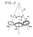
マイクロコイル12は、複数の湾曲したセグメントからなる最低エネルギー状態の二次形状とされ、各セグメントは一つの固有の軸線を規定し、そのため、マイクロコイル12は複数軸線を規定する。更に詳しくは、各湾曲セグメントは、一軸線を有する一平面を規定し、該軸線は該平面に対し実質上垂直である。図1〜4の好ましい実施形態において、湾曲セグメントは、接線で相互接続する実質上円形の閉じたループ14a、14bであり、これらループは、複数の別々の軸線16を規定する。図1に示される好ましい一実施形態において、ループ14a、14bは、実質的に同一平面上にあり、また実質上平行な複数の軸線16を規定する。図3及び4に示される別の好ましい実施形態において、隣接するループ14a、14bの各組は、浅い角度を規定し、これにより、これらループの各軸線16は、各軸線間に90°以下の、好ましくは45°以下の角度(θ1、θ2、θ3及びθ4)を規定する。
The
上記実施形態において、マイクロコイル12は、基端部及び先端部を有するフィラメント(単繊維)状構造であり、該フィラメント状構造は、複数のループを備える最低エネルギー状態二次形状へと形成される。各ループは、平面と該平面に垂直な一つの固有の軸線を規定し、次のようにされる。すなわち、該フィラメント状構造に沿って基端部から先端部へと経路を辿ると、該経路は、各軸線の周りに閉ループ経路セグメントを規定し、該経路セグメントが、連続する複数軸線の周りで時計回りの経路セグメントと反時計回りの経路セグメントとを交互に繰り返す。
In the above embodiment, the
本発明の好ましい実施形態は、一般に、一組の末端ループ14aと、少なくとも一つの中間ループ14bとを含む。典型的には、閉鎖される脈管部位に応じて四つまでの中間ループ14bが存在するが、非常に大きい脈管部位に対し七つ以上となり得る。中間ループは、標的脈管部位(例えば、動脈瘤)の最大径とほぼ等しい直径を有する大きさに作られ、一方、末端ループ14aは、後述する目的のため、わずかに小さい(好ましくは、ほぼ1.5mm小さい)直径を有する。
Preferred embodiments of the present invention generally include a set of
一次マイクロコイル12は、技術的によく知られている熱処理によって二次形状へと形作られる。例えば、焼なました一次コイルは、最初に、適当な形状及び大きさの耐熱材料からなるマンドレルの周囲に巻き付けることにより、二次形状にされ、次いで、指定時間、焼なまし温度にさらされ得る。例えば白金479では、約500℃〜約1000℃、好ましくは約670℃の焼なまし温度が、約30〜90分、好ましくは約60分間維持され、次いで室温まで冷却され、超音波を用いて浄化される。その結果生じた二次形状は、そのため、恒久的なものとなり、またこれはマイクロコイル12の最低エネルギー状態形状となる。
The
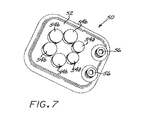
図7は、本発明の好ましい実施形態の製造に使用する熱処理器具50を示す。器具50は、耐熱材料からなり、また基部52を含み、基部52は、二次巻付けのためのマンドレルが設けられる面を有する。マンドレルは、基部52の面から上方に突出する複数の巻付けピン54a、54bを備えている。図示される模範的な器具50は、おおよそ六角形パターンに配列された六つのピンを有する。互いに隣り合う二つの末端巻付けピン54aと、四つの中間巻付けピン54bとが存在する。一組の止めペグ56は、一次コイル12の両端部を固定するために該器具の一端部付近に設けられる。
FIG. 7 shows a heat treatment apparatus 50 used in the manufacture of a preferred embodiment of the present invention. The instrument 50 is made of a heat resistant material and includes a base 52, which has a surface on which a mandrel for secondary winding is provided. The mandrel includes a plurality of winding pins 54 a and 54 b that protrude upward from the surface of the base 52. The illustrated exemplary instrument 50 has six pins arranged in an approximately hexagonal pattern. There are two end winding pins 54a adjacent to each other and four intermediate winding pins 54b. A set of stop pegs 56 is provided near one end of the instrument to secure both ends of the
末端巻付けピン54aの直径は、上述した寸法関係を実現するため、中間巻付けピン54bの直径よりもわずかに小さい。ピン54a、54b間の間隔は、一次コイル12の直径よりもわずかに大きいだけであり、そのため、二次コイルの各巻き線に対して一次コイルの一巻きのみがピン周囲に通され得る。従って、二次コイルの次にくる各巻き線は、前の巻き線上に積み重ねられる。これは、配置中に親動脈内へと二次コイルを押し入れがちとなるであろうどのような直線状区画をも二次コイルにおいて無くす。
The diameter of the end winding pin 54a is slightly smaller than the diameter of the intermediate winding pin 54b in order to realize the dimensional relationship described above. The spacing between the pins 54a, 54b is only slightly larger than the diameter of the
二次巻付け工程中、一次コイル12は、緊張下に保たれる。緊張量は、マイクロコイル12のループ14a、14bのスプリングバックの程度を制御するために調節され得る。
During the secondary winding process, the
マイクロコイル12の二次巻付けは、マイクロコイル12が器具の連続的な各ピンに巻き付けられながら、ループ14a、14bが方向を逆にするように行われる。これは、ループがコイン積層とならないこと、及び、ループが、一旦配置されたら動脈瘤じゅうに不規則に分散配置することを保証する。更には、好ましい実施形態において、各ループは、次のループが巻き付けられる前に360°完全に巻き付けられる。これは、マイクロコイル12が方向を逆にする前に、各ループが動脈瘤内に完全に収容されることを保証する。完全ループそのままで、該ループの強度は最大となり、該ループは負荷を平等に分散する。
Secondary winding of the
図12〜15及び17は、上記の好ましい実施形態の別の形態を示す。特に、図12において、マイクロコイル12’は、複数の連結した湾曲セグメントを含む二次形状を有する。該二次形状において、該複数湾曲セグメントは、部分的に重なる連結した複数閉ループ14’である。該ループは実質上円形で、また、各ループ14’は、別個の軸線16’を規定する。図13において、マイクロコイル12''は、複数の連結湾曲セグメントを含む二次形状を有する。該二次形状において、湾曲セグメントは、接線で相互接続する実質上楕円形状のループ14''である。各ループは、別個の軸線16''を規定する。図14及び15は、ループが異なる直径である点を除いて図1〜4の形態と同様である別の形態を示す。従って、図14において、マイクロコイル12'''は、最大直径のループ14'''cから始まって次第に直径が小さくなる、接線で接続する実質上円形のループ14'''を含む二次形状を有する。各ループは、固有の軸線16'''を有する。図15に示される変形形態は、最大径ループループ14'''cに先行する追加の小径ループ14'''dが存在する点を除き、図14と同様である。図17に示した更なる好ましい実施形態は、最低エネルギー状態二次形状を有するマイクロコイル12ivを備える。該二次形状において、複数の接線相互接続ループ14ivが次のように配列される。すなわち、各ループが一の円の固有半径rと直交する軸線16ivを規定し、これら半径は、円弧θの固定角だけ離される。
12-15 and 17 show another form of the preferred embodiment described above. In particular, in FIG. 12, the microcoil 12 'has a secondary shape that includes a plurality of connected curved segments. In the secondary shape, the multiple curved segments are connected multiple closed loops 14 'that partially overlap. The loops are substantially circular and each loop 14 'defines a separate axis 16'. In FIG. 13, the
図5は、本発明の第1の代替実施形態に従うマイクロコイル脈管閉塞デバイス20を示す。この実施形態は、二次最低エネルギー状態形状へと形成される一次マイクロコイル22を含み、二次最低エネルギー状態形状は、横方向に交互となる開(閉じていない)ループ24の長手方向配列からなる波形状の構造を規定し、これらループは複数の別個の軸線16を規定する。好ましい実施形態として、ループ24が実質上同一平面上にあってそれらの各軸線16が実質上平行である第1の形態と、隣り合うループ24の各組が浅い角度を規定し、そのため各軸線16がこれらの間に約90℃以下、好ましくは約45℃以下の角度を規定する第2の形態とがあり得る。このいずれかの実施形態を製造する材料、寸法及び方法は、すべての重要な点において上述した好ましい実施形態のものと同様である。
FIG. 5 shows a microcoil vaso-
図10は、特定の構成の実施形態を示し、該実施形態において、一次マイクロコイル構造22’は、波形状構造を有する二次最低エネルギー状態形状へと形成される。該二次形状は、実質上正弦波形状を規定し、複数の別個の軸線26’を規定する。該波形状は、少なくとも一つの最高部22aと少なくとも一つの最低部22bを有し、最高部及び最低部各々は、半径rの円弧を規定し、また、各円弧は、長さLの直線区域によって隣り合う円弧と接続し、Lは約2r未満である。
FIG. 10 illustrates an embodiment of a particular configuration, in which the primary microcoil structure 22 'is formed into a secondary lowest energy state shape having a wave shape structure. The secondary shape defines a substantially sinusoidal shape and defines a plurality of distinct axes 26 '. The wave shape has at least one highest portion 22a and at least one
本発明を使用する方法が図6に示される。使用時において、マイクロコイル12(又は22)の基端部は、ガイドワイヤー又はマイクロカテーテル(図示せず)等の細長い送出し(搬入)装置の先端部に取り付けられる。この取付けは、次の米国特許に例示されるような技術的に知られている多くの方法のいずれかによってなされ得る。すなわち、Geremia等の第5,108,407号、Guglielmi等の5,122,136号、Sepetkaの第5,234,437号、Engelsonの5,261,916号、Twyford, Jr.等の第5,304,195号、Palermoの第5,312,415号、Pham等の第5,423,829号、Palermoの第5,522,836号、Northrup等の5,645,564号、Samsonの第5,725,546号、Giaの第5,800,453号、Sepetka等の第5,814,062号、Lee等の第5,911,737号、Saadat等の第5,989,242号、Jacobsen等の第6,022,369号、Diaz等の第6,063,100号、Lulo等の第6,068,644号、及び、Lee等の第6,102,933号である。これらの文献は参照により明確にここに組み込まれる。 A method of using the present invention is shown in FIG. In use, the proximal end of the microcoil 12 (or 22) is attached to the distal end of an elongate delivery (loading) device such as a guide wire or microcatheter (not shown). This attachment can be done by any of a number of methods known in the art as illustrated in the following US patents. Geremia et al., 5,108,407, Guglielmi et al., 5,122,136, Sepetka, 5,234,437, Engelson, 5,261,916, Twyford, Jr. No. 5,304,195, Palermo No. 5,312,415, Pham et al. 5,423,829, Palermo No. 5,522,836, Northrup et al. 5,645,564 Samson 5,725,546, Gia 5,800,453, Sepetka et al. 5,814,062, Lee et al. 5,911,737, Saadat et al. 5,989. No. 242, Jacobsen et al. 6,022,369, Diaz et al. 6,063,100, Lulo et al. 6,068,644, and Lee et al. 6,102,933 is there. These documents are specifically incorporated herein by reference.
標的脈管部位は、技術的に知られている慣用手段により視覚化(映像化)される。視覚化されると、脈管部位は、既知の最大の寸法Dを求めるために測定され得る。該寸法Dは、脈管部位の長さ、幅又は深さであり得る。標的脈管部位は、例えば、親動脈42から分かれた動脈瘤40であり得る。ここで、動脈瘤40は、親動脈に頸部46で接続されるドーム44を有する。本発明に従うマイクロコイル脈管閉塞デバイス12は、その最低エネルギー二次形状において、動脈瘤40の求めた最大寸法Dの好ましくは少なくとも2倍、より好ましくは少なくとも約3倍の全長を有するように選択される。カテーテル30は、動脈瘤40のドーム44内に頸部46を経て入るまで血管内に通される。マイクロコイル12は、動脈瘤40のドーム44に入るまで、ガイドワイヤー又はマイクロカテーテルの支援によりカテーテル30を通って送られる。
The target vascular site is visualized (imaged) by conventional means known in the art. Once visualized, the vascular site can be measured to determine the largest known dimension D. The dimension D can be the length, width or depth of the vascular site. The target vascular site may be, for example, an aneurysm 40 that is separated from the parent artery 42. Here, the aneurysm 40 has a
マイクロコイル12の先端部において小寸法の末端ループ14aが最初に動脈瘤に入る。これは最初のループの適切な収容を支援する。それは、より小さい寸法が該最初のループを、親動脈42を避けて動脈瘤の頸部46内側に保つためである。
At the tip of the
次に中間ループ14bが動脈瘤に入る。これらは動脈瘤に適合する(ぴったり合う)寸法とされているので、動脈瘤の壁に対し最小の摩擦で自由かつ円滑に展開配置され得る。マイクロコイル12の二次形状が本質的に同一面上にあるので、全中間ループは、動脈瘤ドーム44の壁に対し力を及ぼし、これにより、拍動血流による移動に対するマイクロコイル12の抵抗を高める。
The intermediate loop 14b then enters the aneurysm. Since they are sized to fit the aneurysm, they can be deployed freely and smoothly with minimal friction against the wall of the aneurysm. Since the secondary shape of the
マイクロコイル12が動脈瘤に入るにつれ、該マイクロコイルは二次形状を帯びようとする。しかし、二次形状において該マイクロコイルは動脈瘤40の最大寸法Dよりも実質上大きいので、展開配置された形状に抑制され、該形状において該マイクロフィルムは、動脈瘤の周囲面を裏打ちする傾向にある。この配置形状において、マイクロコイルは、その最低エネルギー状態よりも実質的に高いエネルギー状態にある。従って、本デバイスが動脈瘤のような脈管部位内に配置されると、本デバイスの該部位内での閉込めが、本デバイスを、最低エネルギー状態よりも高いエネルギー状態を有する三次元形状を呈するようにさせる。(少なくとも一つの次元において)本デバイスの最低エネルギー状態は、本デバイスが配置された空間よりも大きいので、配置された本デバイスは、動脈瘤壁との密接な接触により、最低エネルギー状態形状へと復帰しないように抑制される。そのため、本デバイスは、周囲の動脈瘤壁面と依然として係合し、これにより、血流力による移動又は転倒を最小限とする。更に、(本デバイスが戻ろうとする)最低エネルギー状態の二次形状は、「コイン積層」を促進するものではなく、これにより、経験する圧縮の程度を最小化する。
As the
マイクロコイル12の基端部における小寸法の末端ループ14aは、動脈瘤に最後に入る。マイクロコイルは、完全に配置された後、技術的によく知られている任意の適当な手段によって送出し(搬入)装置から制御可能に取り外され、これにより、送出し装置が回収されることを可能にし、マイクロコイルを所定部位に残して動脈瘤を閉塞する。取外し後、基端部ループ14aは、動脈瘤40の頸部46内へと丸まり、親動脈42を避ける。
A small sized
マイクロコイルは、上述したように、配置され次第、動脈瘤の周囲を裏打ちする寸法の最大ループ径を有するように設計される。大きい動脈瘤の場合、最大ループ径が次第に小さくなる一又は複数の追加のマイクロコイルを配置することにより、動脈瘤の内部空間のかなりの部分を埋めることが有利である。 As described above, the microcoil is designed to have a maximum loop diameter dimensioned to line around the aneurysm once deployed. For large aneurysms, it is advantageous to fill a substantial portion of the aneurysm interior space by placing one or more additional microcoils with progressively smaller maximum loop diameters.
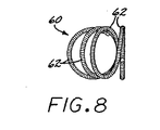
図8及び9は、本発明の第2の代替実施形態に従う脈管閉塞デバイスを示す。この実施形態は、二次最低エネルギー状態形状に形成される一次コイル60を含み、二次形状は、一連の正接の(一点で接する)閉ループ62(好ましくは実施上円形又は楕円形)を形成し、その全体構成は第1円弧角度θ1に対応(規定)し、隣り合う円又は楕円の各組は、それらの間に第2円弧角度θ2を規定する。好ましくは、第1角度θ1は約30°より大きく、第2角度θ2は第1角度θ1の約半分未満である。図示はしないが、各ループは62は軸線を規定し、隣り合うループ62の軸線間の角度は、θ2に等しいことが認識される。
Figures 8 and 9 show a vaso-occlusive device according to a second alternative embodiment of the present invention. This embodiment includes a
図11は、本発明の第3の代替実施形態に従う脈管閉塞デバイスを示す。この実施形態において、マイクロコイル70は、少なくとも一組の連結した等角螺旋(渦巻き)又は対数螺旋72を形成する二次形状を有する。各螺旋は、該各螺旋がなす平面に直交する軸線73を規定する。この仕様の目的のため、等角又は対数螺旋は、すべての動径ベクトルを一定の角度で切断する曲線として定義される。ここで、動径ベクトルRは、該螺旋上の任意の点Pから該螺旋の中心へと引いた線として定義される。特に、上記曲線が螺旋の場合、すなわち、動径角(ラジアル角)(radial angle)θの単調増加関数である動径ベクトルRを有する曲線の場合、該螺旋は、上記角度が動径ベクトルと該螺旋上の任意の点Pに対する接線との間に形成された角度αが一定ならば等角螺旋となる。
FIG. 11 shows a vaso-occlusive device according to a third alternative embodiment of the present invention. In this embodiment, the
図16は、第4の代替実施形態に従う脈管閉塞デバイスを示す。該実施形態において、マイクロコイル80は、一連の相互接続した複雑な(複数の)湾曲セグメント82に似ている二次形状を有する。各セグメントは、球84の表面周りの経路によって定義される。各セグメントは、従って、周囲に上記経路が生じる球84のほぼ中心点に位置する固有の焦点86と、焦点86から延びる、上記球の半径と等しい半径rとによって定義される。各セグメントは、同一平面にある複数の半径によって規定され得るし(セグメントが、これが規定する球の周りの実質的な円周経路によって定義される場合)、又は、球と交差する異なる平面にある複数の半径によって規定され得る(この場合、規定球周りの通路は、円周通路からはずれる)。従って、上記セグメントは、完全な円形(円周通路)又は螺旋ループ(非円周通路)に完全ではないが近似し、セグメントはまた、均一の直径又は異なる直径であり得る。
FIG. 16 shows a vaso-occlusive device according to a fourth alternative embodiment. In the embodiment, the microcoil 80 has a secondary shape resembling a series of interconnected complex
従って、本発明は、先行技術の三次元マイクロコイルに対するいくつかの利点を提示する。例えば、頸部を越えるループの存在により、動脈瘤頸部をカバーする範囲が広がり、更に、本デバイスの一部が親動脈内へと入り込む蓋然性が減る。二次コイル形状はまた、より円滑な展開配置を提供し、一旦配置されると、本装置は、コイルの圧縮に対しより大きな抵抗を示し、これにより、拍動血流に直面しても位置的安定性を高める。この安定性は、本デバイスと動脈瘤壁との間の少なめの全体的摩擦によって実現される。更には、動脈瘤じゅうにわたるループの不規則な分散は、本デバイスが、動脈瘤内で複雑な形状を維持することを可能にし、改善された栓塞形成をもたらす。 The present invention thus presents several advantages over prior art three-dimensional microcoils. For example, the presence of a loop beyond the neck increases the coverage of the aneurysm neck and further reduces the likelihood that a portion of the device will enter the parent artery. The secondary coil shape also provides a smoother deployment arrangement, and once deployed, the device exhibits greater resistance to coil compression, thereby allowing it to be positioned even in the face of pulsatile blood flow. Increases the stability of the machine. This stability is achieved with less overall friction between the device and the aneurysm wall. Furthermore, the irregular distribution of loops across the aneurysm allows the device to maintain a complex shape within the aneurysm, resulting in improved embolization.
本発明の好ましい実施形態及び代替実施形態がここに記述されたが、当然のことながら、多くのバリエーション及び変更が当業者には想定される。例えば、ここに記述したものとは異なる二次形状であって、典型的な動脈瘤の処置に対する本発明の顕著な利点の全部ではないが大部分をもたらすか、又は特定の臨床用途における特別な利点を証明する二次形状も見出され得る。また、特定の用途では、寸法及び材料は、有利であることが判明したなら、ここに開示したものから変更され得る。これらの及び他のバリエーション及び変更は、特許請求の範囲で定義される本発明の精神及び範囲内にあると考えられる。 While preferred and alternative embodiments of the present invention have been described herein, it will be appreciated that many variations and modifications will occur to those skilled in the art. For example, a secondary shape different from that described herein, which provides most if not all of the significant advantages of the present invention for the treatment of typical aneurysms, or is special in certain clinical applications Secondary shapes that prove the benefits can also be found. Also, for certain applications, the dimensions and materials can be varied from those disclosed herein if found to be advantageous. These and other variations and modifications are considered to be within the spirit and scope of the present invention as defined in the claims.
10、20 マイクロコイル脈管閉塞デバイス
12、12’、12''、12'''、12iv、22、22’ マイクロコイル
14a、14b、14’、14''、14'''、14iv、24 ループ
16、16’、16''、16'''、16iv、26’ 軸線
30 カテーテル
40 動脈瘤
42 親動脈
46 頸部
10, 20 Microcoil vaso-
Claims (21)
(a)脈管部位の最大寸法を求める工程と、
(b)相互に接続する複数の湾曲セグメントを備える最低エネルギー状態二次形状へと形成されるフィラメント状構造からなる脈管閉塞デバイスであって、その最低エネルギー状態において、脈管部位の前記最大寸法の少なくとも約2倍の全長を有する当該デバイスを準備する工程と、
(c)前記デバイスが、その最低エネルギー状態よりも実質上高いエネルギー状態を有する形状で脈管部位内に収容され、これにより、該デバイスが、その最低エネルギー状態形状へ戻らないように脈管部位との接触によって抑制されるように脈管部位の内部へと前記デバイスを配置する工程とを含む方法。 A method for closing a vascular site,
(A) determining the maximum dimension of the vascular site;
(B) A vascular occlusion device comprising a filamentary structure formed into a lowest energy state secondary shape comprising a plurality of curved segments connected to each other, wherein the maximum dimension of the vascular site in the lowest energy state Providing the device having a total length of at least about twice as long as
(C) the device is housed within the vascular site in a shape having an energy state substantially higher than its lowest energy state, thereby preventing the device from returning to its lowest energy state shape. Placing the device inside a vascular site so as to be inhibited by contact with the device.
Applications Claiming Priority (2)
| Application Number | Priority Date | Filing Date | Title |
|---|---|---|---|
| US10/247,231 US7029486B2 (en) | 2000-09-26 | 2002-09-19 | Microcoil vaso-occlusive device with multi-axis secondary configuration |
| PCT/US2003/029394 WO2004026149A1 (en) | 2002-09-19 | 2003-09-17 | Microcoil vaso-occlusive device with multi-axis secondary configuration |
Publications (2)
| Publication Number | Publication Date |
|---|---|
| JP2006500108A true JP2006500108A (en) | 2006-01-05 |
| JP2006500108A5 JP2006500108A5 (en) | 2006-11-09 |
Family
ID=32028971
Family Applications (1)
| Application Number | Title | Priority Date | Filing Date |
|---|---|---|---|
| JP2004537987A Pending JP2006500108A (en) | 2002-09-19 | 2003-09-17 | Microcoil vascular occlusion device with multi-axis secondary shape |
Country Status (7)
| Country | Link |
|---|---|
| US (2) | US7029486B2 (en) |
| EP (1) | EP1542599A1 (en) |
| JP (1) | JP2006500108A (en) |
| CN (1) | CN1681440A (en) |
| AU (1) | AU2003267287A1 (en) |
| CA (1) | CA2498192A1 (en) |
| WO (1) | WO2004026149A1 (en) |
Cited By (1)
| Publication number | Priority date | Publication date | Assignee | Title |
|---|---|---|---|---|
| JP2014519886A (en) * | 2011-05-11 | 2014-08-21 | マイクロベンション インコーポレイテッド | Coil packing |
Families Citing this family (39)
| Publication number | Priority date | Publication date | Assignee | Title |
|---|---|---|---|---|
| US7485123B2 (en) * | 2004-03-01 | 2009-02-03 | Boston Scientific Scimed, Inc. | Complex vaso-occlusive coils |
| US7488332B2 (en) * | 2004-03-01 | 2009-02-10 | Boston Scientific Scimed, Inc. | Vaso-occlusive coils with non-overlapping sections |
| EP1793744B1 (en) | 2004-09-22 | 2008-12-17 | Dendron GmbH | Medical implant |
| DE502004010411D1 (en) | 2004-09-22 | 2009-12-31 | Dendron Gmbh | DEVICE FOR IMPLANTING MICROWAVES |
| US8007509B2 (en) * | 2005-10-12 | 2011-08-30 | Boston Scientific Scimed, Inc. | Coil assemblies, components and methods |
| US8545530B2 (en) | 2005-10-19 | 2013-10-01 | Pulsar Vascular, Inc. | Implantable aneurysm closure systems and methods |
| KR101334502B1 (en) | 2005-10-19 | 2013-12-05 | 펄사 배스큘러, 아이엔씨. | Method and systems for endovascularly clipping and repairing lumen and tissue defects |
| US20070225738A1 (en) * | 2006-03-24 | 2007-09-27 | Cook Incorporated | Aneurysm coil and method of assembly |
| EP2015683B1 (en) | 2006-04-17 | 2015-12-09 | Covidien LP | System for mechanically positioning intravascular implants |
| US8777979B2 (en) | 2006-04-17 | 2014-07-15 | Covidien Lp | System and method for mechanically positioning intravascular implants |
| JP5227344B2 (en) * | 2007-03-13 | 2013-07-03 | タイコ ヘルスケア グループ リミテッド パートナーシップ | Implant, mandrel, and implant formation method |
| JP5249249B2 (en) | 2007-03-13 | 2013-07-31 | コヴィディエン リミテッド パートナーシップ | Implant including a coil and a stretch resistant member |
| US10028747B2 (en) | 2008-05-01 | 2018-07-24 | Aneuclose Llc | Coils with a series of proximally-and-distally-connected loops for occluding a cerebral aneurysm |
| US10716573B2 (en) | 2008-05-01 | 2020-07-21 | Aneuclose | Janjua aneurysm net with a resilient neck-bridging portion for occluding a cerebral aneurysm |
| CN102202585B (en) | 2008-09-05 | 2014-04-02 | 帕尔萨脉管公司 | Systems and methods for supporting or occluding a physiological opening or cavity |
| US9089405B1 (en) * | 2008-09-12 | 2015-07-28 | Microvention, Inc. | Three-dimensional complex coil |
| WO2010085344A1 (en) | 2009-01-22 | 2010-07-29 | Cornell University | Method and apparatus for restricting flow through the wall of a lumen |
| EP3300674A1 (en) | 2009-09-04 | 2018-04-04 | Pulsar Vascular, Inc. | Systems for enclosing an anatomical opening |
| US9358140B1 (en) | 2009-11-18 | 2016-06-07 | Aneuclose Llc | Stent with outer member to embolize an aneurysm |
| WO2012135859A2 (en) * | 2011-04-01 | 2012-10-04 | Cornell University | Method and apparatus for restricting flow through an opening in the side wall of a body lumen, and/or for reinforcing a weakness in the side wall of a body lumen, while still maintaining substantially normal flow through the body lumen |
| CA2837717C (en) | 2011-06-03 | 2019-07-09 | Pulsar Vascular, Inc. | Systems and methods for enclosing an anatomical opening, including shock absorbing aneurysm devices |
| KR102018035B1 (en) | 2011-06-03 | 2019-09-05 | 펄사 배스큘라, 아이엔씨. | Aneurysm devices with additional anchoring mechanisms and associated systems and methods |
| US9119625B2 (en) | 2011-10-05 | 2015-09-01 | Pulsar Vascular, Inc. | Devices, systems and methods for enclosing an anatomical opening |
| US9579104B2 (en) | 2011-11-30 | 2017-02-28 | Covidien Lp | Positioning and detaching implants |
| US9011480B2 (en) | 2012-01-20 | 2015-04-21 | Covidien Lp | Aneurysm treatment coils |
| US9687245B2 (en) | 2012-03-23 | 2017-06-27 | Covidien Lp | Occlusive devices and methods of use |
| US9259229B2 (en) | 2012-05-10 | 2016-02-16 | Pulsar Vascular, Inc. | Systems and methods for enclosing an anatomical opening, including coil-tipped aneurysm devices |
| JP6119749B2 (en) * | 2012-06-29 | 2017-04-26 | 株式会社カネカ | Method for producing in-vivo indwelling member |
| US9681876B2 (en) | 2013-07-31 | 2017-06-20 | EMBA Medical Limited | Methods and devices for endovascular embolization |
| US10010328B2 (en) | 2013-07-31 | 2018-07-03 | NeuVT Limited | Endovascular occlusion device with hemodynamically enhanced sealing and anchoring |
| US10398441B2 (en) | 2013-12-20 | 2019-09-03 | Terumo Corporation | Vascular occlusion |
| CN106102600B (en) | 2014-02-27 | 2019-09-27 | 因库麦迪斯有限公司 | Embolism framework microcoils |
| US9713475B2 (en) | 2014-04-18 | 2017-07-25 | Covidien Lp | Embolic medical devices |
| US20150327868A1 (en) | 2014-05-13 | 2015-11-19 | Ndi Tip Teknolojileri Anonim Sirketi | Retractable and rapid disconnect, floating diameter embolic coil product and delivery system |
| US10307168B2 (en) | 2015-08-07 | 2019-06-04 | Terumo Corporation | Complex coil and manufacturing techniques |
| CN114732470A (en) * | 2015-12-30 | 2022-07-12 | 斯瑞克公司 | Embolization device and method of making same |
| US10842607B2 (en) | 2016-10-14 | 2020-11-24 | Microvention, Inc. | Embolic coils |
| JP7423865B2 (en) * | 2021-11-11 | 2024-01-29 | ストライカー コーポレイション | Vascular occlusion device and method of manufacturing and using the same |
| CN115192113B (en) * | 2022-08-09 | 2023-06-02 | 惠州市顺美医疗科技有限公司 | Frame micro-spring for treating vascular diseases and processing technology thereof |
Family Cites Families (103)
| Publication number | Priority date | Publication date | Assignee | Title |
|---|---|---|---|---|
| US407818A (en) * | 1889-07-30 | Island | ||
| US421304A (en) * | 1890-02-11 | Teollet for electric railways | ||
| US427680A (en) * | 1890-05-13 | good-son | ||
| HU184722B (en) * | 1980-02-18 | 1984-10-29 | Laszlo Lazar | Therapeutically suitable silicone rubber mixture and therapeuticaid |
| JPH0678460B2 (en) | 1985-05-01 | 1994-10-05 | 株式会社バイオマテリアル・ユニバース | Porous transparent polyvinyl alcohol gel |
| US4739768B2 (en) | 1986-06-02 | 1995-10-24 | Target Therapeutics Inc | Catheter for guide-wire tracking |
| US4800882A (en) * | 1987-03-13 | 1989-01-31 | Cook Incorporated | Endovascular stent and delivery system |
| US4795741A (en) * | 1987-05-06 | 1989-01-03 | Biomatrix, Inc. | Compositions for therapeutic percutaneous embolization and the use thereof |
| US4819637A (en) * | 1987-09-01 | 1989-04-11 | Interventional Therapeutics Corporation | System for artificial vessel embolization and devices for use therewith |
| FR2632864B2 (en) | 1987-12-31 | 1990-10-19 | Biomat Sarl | ANTI-EMBOLIC ELASTIC FILTERING SYSTEM FOR CELLAR VEIN AND ASSEMBLY OF MEANS FOR ITS PLACEMENT |
| US4884579A (en) | 1988-04-18 | 1989-12-05 | Target Therapeutics | Catheter guide wire |
| US4994069A (en) * | 1988-11-02 | 1991-02-19 | Target Therapeutics | Vaso-occlusion coil and method |
| US5162430A (en) | 1988-11-21 | 1992-11-10 | Collagen Corporation | Collagen-polymer conjugates |
| US6083220A (en) | 1990-03-13 | 2000-07-04 | The Regents Of The University Of California | Endovascular electrolytically detachable wire and tip for the formation of thrombus in arteries, veins, aneurysms, vascular malformations and arteriovenous fistulas |
| US5122136A (en) * | 1990-03-13 | 1992-06-16 | The Regents Of The University Of California | Endovascular electrolytically detachable guidewire tip for the electroformation of thrombus in arteries, veins, aneurysms, vascular malformations and arteriovenous fistulas |
| US5108407A (en) * | 1990-06-08 | 1992-04-28 | Rush-Presbyterian St. Luke's Medical Center | Method and apparatus for placement of an embolic coil |
| US5133731A (en) * | 1990-11-09 | 1992-07-28 | Catheter Research, Inc. | Embolus supply system and method |
| US6524274B1 (en) | 1990-12-28 | 2003-02-25 | Scimed Life Systems, Inc. | Triggered release hydrogel drug delivery system |
| DE4104702C2 (en) * | 1991-02-15 | 1996-01-18 | Malte Neuss | Implants for organ pathways in spiral form |
| US5350398A (en) | 1991-05-13 | 1994-09-27 | Dusan Pavcnik | Self-expanding filter for percutaneous insertion |
| US5226911A (en) * | 1991-10-02 | 1993-07-13 | Target Therapeutics | Vasoocclusion coil with attached fibrous element(s) |
| US5304194A (en) * | 1991-10-02 | 1994-04-19 | Target Therapeutics | Vasoocclusion coil with attached fibrous element(s) |
| US5261916A (en) * | 1991-12-12 | 1993-11-16 | Target Therapeutics | Detachable pusher-vasoocclusive coil assembly with interlocking ball and keyway coupling |
| US5234437A (en) * | 1991-12-12 | 1993-08-10 | Target Therapeutics, Inc. | Detachable pusher-vasoocclusion coil assembly with threaded coupling |
| DK0617594T3 (en) * | 1991-12-12 | 1998-02-02 | Target Therapeutics Inc | Separate ejector body lock coil construction with interlocking coupling |
| US5258042A (en) | 1991-12-16 | 1993-11-02 | Henry Ford Health System | Intravascular hydrogel implant |
| US5307194A (en) * | 1992-03-24 | 1994-04-26 | Grumman Aerospace Corporation | Covert communication system using ultraviolet light |
| US5342387A (en) * | 1992-06-18 | 1994-08-30 | American Biomed, Inc. | Artificial support for a blood vessel |
| US5527338A (en) * | 1992-09-02 | 1996-06-18 | Board Of Regents, The University Of Texas System | Intravascular device |
| USRE37117E1 (en) | 1992-09-22 | 2001-03-27 | Target Therapeutics, Inc. | Detachable embolic coil assembly using interlocking clasps and method of use |
| US5312415A (en) * | 1992-09-22 | 1994-05-17 | Target Therapeutics, Inc. | Assembly for placement of embolic coils using frictional placement |
| US5350397A (en) * | 1992-11-13 | 1994-09-27 | Target Therapeutics, Inc. | Axially detachable embolic coil assembly |
| US5382259A (en) | 1992-10-26 | 1995-01-17 | Target Therapeutics, Inc. | Vasoocclusion coil with attached tubular woven or braided fibrous covering |
| US5382260A (en) * | 1992-10-30 | 1995-01-17 | Interventional Therapeutics Corp. | Embolization device and apparatus including an introducer cartridge and method for delivering the same |
| US5690666A (en) * | 1992-11-18 | 1997-11-25 | Target Therapeutics, Inc. | Ultrasoft embolism coils and process for using them |
| CA2144725C (en) | 1992-11-19 | 2000-06-06 | Uriel Hiram Chee | Large diameter vasoocclusion coil |
| US5423829A (en) * | 1993-11-03 | 1995-06-13 | Target Therapeutics, Inc. | Electrolytically severable joint for endovascular embolic devices |
| ES2227547T3 (en) * | 1994-03-18 | 2005-04-01 | Cook Incorporated | HELICOIDAL EMBOLIZATION COIL. |
| JP2535785B2 (en) * | 1994-06-03 | 1996-09-18 | 工業技術院長 | Vascular embolic agent |
| US5725546A (en) * | 1994-06-24 | 1998-03-10 | Target Therapeutics, Inc. | Detachable microcoil delivery catheter |
| US5549624A (en) | 1994-06-24 | 1996-08-27 | Target Therapeutics, Inc. | Fibered vasooclusion coils |
| US5522836A (en) * | 1994-06-27 | 1996-06-04 | Target Therapeutics, Inc. | Electrolytically severable coil assembly with movable detachment point |
| US5690671A (en) * | 1994-12-13 | 1997-11-25 | Micro Interventional Systems, Inc. | Embolic elements and methods and apparatus for their delivery |
| US5578074A (en) * | 1994-12-22 | 1996-11-26 | Target Therapeutics, Inc. | Implant delivery method and assembly |
| US5814062A (en) * | 1994-12-22 | 1998-09-29 | Target Therapeutics, Inc. | Implant delivery assembly with expandable coupling/decoupling mechanism |
| USD407818S (en) * | 1995-03-31 | 1999-04-06 | Target Therapeutics, Inc. | Spiral vaso-occlusion coil |
| US6171326B1 (en) | 1998-08-27 | 2001-01-09 | Micrus Corporation | Three dimensional, low friction vasoocclusive coil, and method of manufacture |
| US5645558A (en) * | 1995-04-20 | 1997-07-08 | Medical University Of South Carolina | Anatomically shaped vasoocclusive device and method of making the same |
| US6638291B1 (en) | 1995-04-20 | 2003-10-28 | Micrus Corporation | Three dimensional, low friction vasoocclusive coil, and method of manufacture |
| US5911731A (en) * | 1995-04-20 | 1999-06-15 | Target Therapeutics, Inc. | Anatomically shaped vasoocclusive devices |
| US5639277A (en) | 1995-04-28 | 1997-06-17 | Target Therapeutics, Inc. | Embolic coils with offset helical and twisted helical shapes |
| US5645564A (en) * | 1995-05-22 | 1997-07-08 | Regents Of The University Of California | Microfabricated therapeutic actuator mechanisms |
| US5624461A (en) * | 1995-06-06 | 1997-04-29 | Target Therapeutics, Inc. | Three dimensional in-filling vaso-occlusive coils |
| US6004448A (en) | 1995-06-06 | 1999-12-21 | Atotech Usa, Inc. | Deposition of chromium oxides from a trivalent chromium solution containing a complexing agent for a buffer |
| NO962336L (en) * | 1995-06-06 | 1996-12-09 | Target Therapeutics Inc | Vaso-occlusive spiral |
| US6176240B1 (en) * | 1995-06-07 | 2001-01-23 | Conceptus, Inc. | Contraceptive transcervical fallopian tube occlusion devices and their delivery |
| WO1997001368A1 (en) * | 1995-06-26 | 1997-01-16 | Trimedyne, Inc. | Therapeutic appliance releasing device |
| US6013084A (en) | 1995-06-30 | 2000-01-11 | Target Therapeutics, Inc. | Stretch resistant vaso-occlusive coils (II) |
| US5582619A (en) * | 1995-06-30 | 1996-12-10 | Target Therapeutics, Inc. | Stretch resistant vaso-occlusive coils |
| US5580568A (en) * | 1995-07-27 | 1996-12-03 | Micro Therapeutics, Inc. | Cellulose diacetate compositions for use in embolizing blood vessels |
| DE29518932U1 (en) | 1995-11-29 | 1996-06-20 | Reul Juergen Dr Med | Controlled detachable embolization ball spiral |
| US5658308A (en) * | 1995-12-04 | 1997-08-19 | Target Therapeutics, Inc. | Bioactive occlusion coil |
| US5649949A (en) * | 1996-03-14 | 1997-07-22 | Target Therapeutics, Inc. | Variable cross-section conical vasoocclusive coils |
| US5868754A (en) | 1996-06-12 | 1999-02-09 | Target Therapeutics, Inc. | Medical retrieval device |
| GB9614950D0 (en) | 1996-07-16 | 1996-09-04 | Anson Medical Ltd | A ductus stent and delivery catheter |
| US6096034A (en) * | 1996-07-26 | 2000-08-01 | Target Therapeutics, Inc. | Aneurysm closure device assembly |
| US5980514A (en) * | 1996-07-26 | 1999-11-09 | Target Therapeutics, Inc. | Aneurysm closure device assembly |
| US5676697A (en) | 1996-07-29 | 1997-10-14 | Cardiovascular Dynamics, Inc. | Two-piece, bifurcated intraluminal graft for repair of aneurysm |
| JP3784112B2 (en) * | 1996-08-15 | 2006-06-07 | 株式会社カネカメディックス | Coiled embolic material |
| US5690667A (en) * | 1996-09-26 | 1997-11-25 | Target Therapeutics | Vasoocclusion coil having a polymer tip |
| US5895278A (en) * | 1996-10-10 | 1999-04-20 | Thomas & Betts Corporation | Controlled impedance, high density electrical connector |
| US6984240B1 (en) | 1996-10-25 | 2006-01-10 | Target Therapeutics, Inc. | Detachable multidiameter vasoocclusive coil |
| US5733329A (en) * | 1996-12-30 | 1998-03-31 | Target Therapeutics, Inc. | Vaso-occlusive coil with conical end |
| US5911737A (en) * | 1997-02-28 | 1999-06-15 | The Regents Of The University Of California | Microfabricated therapeutic actuators |
| US5895378A (en) | 1997-05-29 | 1999-04-20 | Target Therapeutics, Inc. | Flow-directed catheter having multiple tapers and radio-opaque markers |
| US6860893B2 (en) | 1997-08-29 | 2005-03-01 | Boston Scientific Scimed, Inc. | Stable coil designs |
| US6322576B1 (en) | 1997-08-29 | 2001-11-27 | Target Therapeutics, Inc. | Stable coil designs |
| ES2343228T3 (en) | 1998-02-10 | 2010-07-26 | Ethicon Endo-Surgery, Inc. | OCLUSION, ANCHORAGE, TENSIONING OR STEERING EQUIPMENT BY FLOW. |
| US6022369A (en) * | 1998-02-13 | 2000-02-08 | Precision Vascular Systems, Inc. | Wire device with detachable end |
| US6068644A (en) * | 1998-03-10 | 2000-05-30 | Cordis Corporation | Embolic coil hydraulic deployment system having improved catheter |
| US6063100A (en) * | 1998-03-10 | 2000-05-16 | Cordis Corporation | Embolic coil deployment system with improved embolic coil |
| US6015424A (en) * | 1998-04-28 | 2000-01-18 | Microvention, Inc. | Apparatus and method for vascular embolization |
| US6165193A (en) | 1998-07-06 | 2000-12-26 | Microvention, Inc. | Vascular embolization with an expansible implant |
| US6165194A (en) * | 1998-07-24 | 2000-12-26 | Micrus Corporation | Intravascular flow modifier and reinforcement device |
| US6656218B1 (en) | 1998-07-24 | 2003-12-02 | Micrus Corporation | Intravascular flow modifier and reinforcement device |
| USD421304S (en) * | 1998-08-04 | 2000-02-29 | Target Therapeutics, Inc. | Spiral vaso-occlusion coil |
| US6478773B1 (en) | 1998-12-21 | 2002-11-12 | Micrus Corporation | Apparatus for deployment of micro-coil using a catheter |
| WO2000021443A1 (en) | 1998-10-09 | 2000-04-20 | Cook Incorporated | Vasoocclusion coil device having a core therein |
| US6322567B1 (en) | 1998-12-14 | 2001-11-27 | Integrated Surgical Systems, Inc. | Bone motion tracking system |
| SE9804346D0 (en) | 1998-12-16 | 1998-12-16 | Valmet Corp | Method and apparatus for calendering paper |
| US6585756B1 (en) | 1999-05-14 | 2003-07-01 | Ernst P. Strecker | Implantable lumen prosthesis |
| US6280457B1 (en) | 1999-06-04 | 2001-08-28 | Scimed Life Systems, Inc. | Polymer covered vaso-occlusive devices and methods of producing such devices |
| USD427680S (en) * | 1999-08-18 | 2000-07-04 | Target Therapeutics, Inc. | Spiral vaso-occlusion coil |
| US6790218B2 (en) | 1999-12-23 | 2004-09-14 | Swaminathan Jayaraman | Occlusive coil manufacture and delivery |
| US7033374B2 (en) * | 2000-09-26 | 2006-04-25 | Microvention, Inc. | Microcoil vaso-occlusive device with multi-axis secondary configuration |
| US6605101B1 (en) | 2000-09-26 | 2003-08-12 | Microvention, Inc. | Microcoil vaso-occlusive device with multi-axis secondary configuration |
| US6635069B1 (en) | 2000-10-18 | 2003-10-21 | Scimed Life Systems, Inc. | Non-overlapping spherical three-dimensional coil |
| US6589265B1 (en) | 2000-10-31 | 2003-07-08 | Endovascular Technologies, Inc. | Intrasaccular embolic device |
| WO2003039376A1 (en) | 2001-11-07 | 2003-05-15 | Microvention, Inc. | Microcoil vaso-occlusive device with multi-axis secondary configuration |
| US20030120302A1 (en) * | 2001-12-20 | 2003-06-26 | Scimed Life Systems, Inc. | Vaso-occlusive device with serpentine shape |
| US7229454B2 (en) | 2003-01-07 | 2007-06-12 | Boston Scientific Scimed, Inc. | Occlusive cinching devices and methods of use |
| US20050132621A1 (en) * | 2003-12-23 | 2005-06-23 | Bostick Charles R.Ii | Craft set and elements for constructing pop-up cards |
| US7485123B2 (en) | 2004-03-01 | 2009-02-03 | Boston Scientific Scimed, Inc. | Complex vaso-occlusive coils |
-
2002
- 2002-09-19 US US10/247,231 patent/US7029486B2/en not_active Expired - Lifetime
-
2003
- 2003-09-17 AU AU2003267287A patent/AU2003267287A1/en not_active Abandoned
- 2003-09-17 JP JP2004537987A patent/JP2006500108A/en active Pending
- 2003-09-17 WO PCT/US2003/029394 patent/WO2004026149A1/en active Application Filing
- 2003-09-17 EP EP03749761A patent/EP1542599A1/en not_active Withdrawn
- 2003-09-17 CA CA002498192A patent/CA2498192A1/en not_active Abandoned
- 2003-09-17 CN CNA038223902A patent/CN1681440A/en active Pending
-
2006
- 2006-04-05 US US11/398,081 patent/US8323306B2/en not_active Expired - Lifetime
Cited By (4)
| Publication number | Priority date | Publication date | Assignee | Title |
|---|---|---|---|---|
| JP2014519886A (en) * | 2011-05-11 | 2014-08-21 | マイクロベンション インコーポレイテッド | Coil packing |
| US10299798B2 (en) | 2011-05-11 | 2019-05-28 | Microvention, Inc. | Packing coil |
| US10722242B2 (en) | 2011-05-11 | 2020-07-28 | Microvention, Inc. | Packing coil |
| US11337708B2 (en) | 2011-05-11 | 2022-05-24 | Microvention, Inc. | Packing coil |
Also Published As
| Publication number | Publication date |
|---|---|
| CA2498192A1 (en) | 2004-04-01 |
| CN1681440A (en) | 2005-10-12 |
| EP1542599A1 (en) | 2005-06-22 |
| US20060184195A1 (en) | 2006-08-17 |
| US20030018356A1 (en) | 2003-01-23 |
| US7029486B2 (en) | 2006-04-18 |
| US8323306B2 (en) | 2012-12-04 |
| AU2003267287A1 (en) | 2004-04-08 |
| WO2004026149A1 (en) | 2004-04-01 |
Similar Documents
| Publication | Publication Date | Title |
|---|---|---|
| US8323306B2 (en) | Microcoil vaso-occlusive device with multi-axis secondary configuration | |
| US7033374B2 (en) | Microcoil vaso-occlusive device with multi-axis secondary configuration | |
| US7331974B2 (en) | Microcoil vaso-occlusive device with multi-axis secondary configuration | |
| US8308751B2 (en) | Foldable vaso-occlusive member | |
| US10722242B2 (en) | Packing coil | |
| US20050192618A1 (en) | Complex vaso-occlusive coils | |
| US9089405B1 (en) | Three-dimensional complex coil | |
| JP4109627B2 (en) | Microcoil vascular occlusion device with multi-axis secondary shape | |
| AU2002236676A1 (en) | Microcoil vaso-occlusive device with multi-axis secondary configuration | |
| CN101045005A (en) | Microcoil vaso-occlusive device with multi-axis secondary configuration |
Legal Events
| Date | Code | Title | Description |
|---|---|---|---|
| A521 | Request for written amendment filed |
Free format text: JAPANESE INTERMEDIATE CODE: A523 Effective date: 20060919 |
|
| A621 | Written request for application examination |
Free format text: JAPANESE INTERMEDIATE CODE: A621 Effective date: 20060919 |
|
| A131 | Notification of reasons for refusal |
Free format text: JAPANESE INTERMEDIATE CODE: A131 Effective date: 20090623 |
|
| A601 | Written request for extension of time |
Free format text: JAPANESE INTERMEDIATE CODE: A601 Effective date: 20090924 |
|
| RD04 | Notification of resignation of power of attorney |
Free format text: JAPANESE INTERMEDIATE CODE: A7424 Effective date: 20090924 |
|
| A602 | Written permission of extension of time |
Free format text: JAPANESE INTERMEDIATE CODE: A602 Effective date: 20091001 |
|
| A02 | Decision of refusal |
Free format text: JAPANESE INTERMEDIATE CODE: A02 Effective date: 20100302 |