JP2006352719A - Apparatus, method for monitoring network, network system, network monitoring method and network communication method - Google Patents
Apparatus, method for monitoring network, network system, network monitoring method and network communication method Download PDFInfo
- Publication number
- JP2006352719A JP2006352719A JP2005178697A JP2005178697A JP2006352719A JP 2006352719 A JP2006352719 A JP 2006352719A JP 2005178697 A JP2005178697 A JP 2005178697A JP 2005178697 A JP2005178697 A JP 2005178697A JP 2006352719 A JP2006352719 A JP 2006352719A
- Authority
- JP
- Japan
- Prior art keywords
- network
- quarantine
- address
- frame
- node
- Prior art date
- Legal status (The legal status is an assumption and is not a legal conclusion. Google has not performed a legal analysis and makes no representation as to the accuracy of the status listed.)
- Pending
Links
Images


Abstract
Description
本発明は、ネットワーク監視装置,ネットワーク監視方法,ネットワークシステム及びネットワーク監視方法及びネットワーク通信方法に関する。 The present invention relates to a network monitoring device, a network monitoring method, a network system, a network monitoring method, and a network communication method.
社内LANなど保護されたネットワークを保護するため、ネットワークへの接続を制限する、いわゆる、ネットワーク監視装置が知られている。このような技術は、例えば、特開2003−303118号公報に記載されている。 In order to protect a protected network such as an in-house LAN, a so-called network monitoring device that restricts connection to the network is known. Such a technique is described in, for example, Japanese Patent Application Laid-Open No. 2003-303118.
このような検疫ネットワークで、特に、外部から持ち込まれたコンピュータなどを、保護されたネットワークへの接続を許可する前に、当該コンピュータのオペレーティングシステムやウィルス検出ソフトがアップデートされているか確認し、アップデートされていない場合、当該コンピュータのオペレーティングシステムやウィルス検出ソフトのバージョンアップソフトを供給する必要がある。 In such a quarantine network, check that the computer's operating system and virus detection software have been updated, especially before allowing computers brought in from outside to connect to the protected network. If not, it is necessary to supply an upgrade system for the operating system of the computer or virus detection software.
そのためには、認証スイッチを利用することが考えられる。すなわち、外部から持ち込まれたコンピュータを社内LANなどの保護されたネットワークに接続する際、検疫ネットワーク機能をサポートしたスイッチングハブがそのコンピュータが接続されたポートを、保護されたネットワークとは仮想的に切り離されたヴァーチャルLAN(VLAN)により構成された検疫ネットワークに接続した。そして、検疫ネットワーク上でオペレーティングシステム(OS)やウィルス検出ソフトのアップデートが完了すると、スイッチングハブが当該コンピュータが接続されたポートを保護されたネットワーク側に所属するようVLANの設定を変更する。 For this purpose, it is conceivable to use an authentication switch. In other words, when a computer brought in from outside is connected to a protected network such as an in-house LAN, the switching hub that supports the quarantine network function virtually disconnects the port to which the computer is connected from the protected network. Connected to a quarantine network configured by a virtual LAN (VLAN). When the operating system (OS) and virus detection software are updated on the quarantine network, the switching hub changes the VLAN setting so that the port connected to the computer belongs to the protected network side.
しかしながら、保護されたネットワークにおいて、端末が接続するスイッチングハブから、検疫サーバが接続するスイッチングハブまで、その経路上のすべてのスイッチングハブが検疫ネットワーク機能をサポートすることが必要である。 However, in a protected network, it is necessary that all switching hubs on the path from the switching hub to which the terminal is connected to the switching hub to which the quarantine server is connected support the quarantine network function.
また、認証DHCP方式を利用することが考えられる。すなわち、外部から持ち込まれたコンピュータがDHCPを用いてIPアドレスを取得する際、DHCPサーバが検疫ネットワーク用のIPアドレスとデフォルトゲートウェイIPアドレスを当該コンピュータに割り当てる。検疫ネットワーク用のIPアドレスは保護されたネットワークとはIPアドレス体系が異なるため、当該コンピュータが保護されたネットワーク内の装置と通信することはできない。当該コンピュータは検疫ネットワーク上でOSやウィルス検出ソフトのアップデートが完了すると、保護されたネットワークと接続可能なIPアドレスやデフォルトゲートウェイIPアドレスが再び割り当てられ、保護されたネットワーク内の装置と通信することが可能となる。 It is also conceivable to use an authentication DHCP method. That is, when a computer brought in from the outside acquires an IP address using DHCP, the DHCP server assigns an IP address for the quarantine network and a default gateway IP address to the computer. Since the IP address system for the quarantine network is different from the protected network, the computer cannot communicate with the devices in the protected network. When the update of the OS and virus detection software is completed on the quarantine network, the computer is reassigned an IP address that can be connected to the protected network and a default gateway IP address, and can communicate with devices in the protected network. It becomes possible.
また、保護されたネットワークがDHCPを用いる環境でなら適用できるが、IPアドレスを固定で割り振るネットワーク環境では適用することができず、また、DHCPを用いる環境であってもIPアドレスを固定で割り当てた装置に対しては効果がない。 Also, it can be applied if the protected network is an environment using DHCP, but cannot be applied in a network environment in which IP addresses are fixedly allocated, and an IP address is fixedly assigned even in an environment using DHCP. There is no effect on the device.
さらに、パーソナル・ファイアウォールを利用することが考えれえる。すなわち、保護されたネットワークと接続するコンピュータにあらかじめファイアウォール機能を持つソフトウェアをインストールしておく。当該コンピュータが保護されたネットワークに接続しようとした際は、OSやウィルス検出ソフトのアップデートプログラムが保存された検疫サーバとのみ通信できるよう、パーソナル・ファイアウォールが通信を制限する。アップデートが完了するとパーソナル・ファイアウォールの制限が解除され、保護されたネットワーク内の装置と通信が可能になる。 Furthermore, it is conceivable to use a personal firewall. That is, software having a firewall function is installed in advance on a computer connected to the protected network. When the computer tries to connect to a protected network, the personal firewall restricts communication so that it can communicate only with the quarantine server in which the OS and virus detection software update program are stored. When the update is complete, the personal firewall restrictions are removed and communication with devices in the protected network is possible.
しかしながら、保護されたネットワークに接続する可能性があるコンピュータにあらかじめパーソナル・ファイアウォールのソフトウェアをインストールする必要があり、これがインストールされていない装置に対しては効果がない。 However, it is necessary to install personal firewall software in advance on a computer that may be connected to a protected network, which is not effective for a device on which this is not installed.
本発明の目的は、上記した問題点の少なくとも1つを解決し、画可能なネットワーク監視装置,ネットワーク監視方法,ネットワークシステム及びネットワーク監視方法及びネットワーク通信方法を提供することにある。 An object of the present invention is to solve at least one of the above-described problems and provide a network monitoring device, a network monitoring method, a network system, a network monitoring method, and a network communication method capable of drawing.
上記目的を達成するために、本発明では、フレームを受信部で受信し、該受信が、検疫対象のノードから送信されたフレームである場合、検疫対象のノードと検疫情報を格納するノードとの通信を妨げず、他のノードについてのネットワークアドレスと前記ネットワークより高い層における相応するアドレスの組合せが含まれないよう演算処理し、送信部からフレームを送信するように構成した。 In order to achieve the above object, in the present invention, when a frame is received by a receiving unit, and the reception is a frame transmitted from a quarantine target node, a node between the quarantine target node and a node storing quarantine information. The communication processing is performed so that a combination of a network address for another node and a corresponding address in a higher layer than the network is not included, and a frame is transmitted from the transmission unit.
具体的には、イーサネット上のイーサフレームを受信するフレーム受信処理部と、イーサフレームを送信するフレーム送信処理部と、検疫ネットワークに接続する装置に関する情報を蓄える接続可否情報テーブルと、受信したイーサフレームと接続可否情報テーブルからARPフレーム送信を判断する接続可否判断処理部と、接続可否判断処理部からの指示に従いARPフレームを送信するARP応答フレーム生成部と、検疫に必要となるソフトウェアを記憶するOS/ウィルス検出ソフトのアップデートデータ保存部を備える、イーサネットのブロードキャストドメインに接続する監視装置を用い、検疫対象装置からのARP要求に応じてARP応答を送信することで検疫ネットワークを実現したものである。 Specifically, a frame reception processing unit that receives an Ethernet frame on Ethernet, a frame transmission processing unit that transmits an Ethernet frame, a connection availability information table that stores information about devices connected to the quarantine network, and the received Ethernet frame A connection availability determination processing unit that determines ARP frame transmission from the connection availability information table, an ARP response frame generation unit that transmits an ARP frame according to an instruction from the connection availability determination processing unit, and an OS that stores software necessary for quarantine / A quarantine network is realized by transmitting an ARP response in response to an ARP request from a quarantine target device using a monitoring device connected to an Ethernet broadcast domain and provided with an update data storage unit of virus detection software.
本発明によれば、外部から持ち込まれたコンピュータ等のノードに対して、ネットワークのノードへの通信を許可する前に、コンピュータのオペレーティングシステムやウィルス検出ソフト等を適切なバージョンに保つすることが可能となる。 According to the present invention, it is possible to keep a computer operating system, virus detection software, and the like at an appropriate version before allowing a node such as a computer brought in from the outside to communicate with a network node. It becomes.
以下、本発明の実施例を図面を用いて説明する。図1は本発明の検疫ネットワーク方式の実施例1である。本構成例では、イーサネットによる1つのブロードキャスト・ドメインからなるネットワーク104に、監視装置100と、いくつかの装置101a〜101b、検疫対象装置103が接続されている。本実施例では、OS/ウィルス検出ソフトのアップデートデータを保持する検疫サーバを監視装置100が兼ねる。
Embodiments of the present invention will be described below with reference to the drawings. FIG. 1 shows a first embodiment of the quarantine network system of the present invention. In this configuration example, a
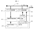
図2は本実施例における監視装置100の構成であり、ネットワーク104に接続するフレーム受信処理部201,フレーム送信処理部202,OS/ウィルス検出ソフトのアップデートデータ保存部203,接続可否判断処理部204,接続可否情報テーブル205,ARP応答フレーム生成部206からなる。なお、ARP (Address Resolution
Protocol) は、TCP/IPプロトコルにおいて、IPアドレスからMACアドレスを求めるためのプロトコルのことである。具体的には、自分のイーサーネットアドレスと自分のIPアドレス、そして通信先のIPアドレスの3つの組を、ARP要求として、LAN上へブロードキャストする。LAN上の各ノードはARP問い合わせのブロードキャストを監視しているので、自分のIPアドレスが指定されていれば、ARP応答として、パケットに自分のMACアドレスを入れて応答を返す。このARP要求と、ARP応答によって、IPアドレスからMACアドレスを得る。なお、MACアドレスとは、イーサーネットでフレームの送受信を行うための物理的なアドレスであり、世界中で同じ物理アドレスを持つことがないように、すべて異なる固有のアドレスが割り当てられている。また、
IPアドレスは、TCP/IPプロトコルを使用しているネットワーク等で、サーバやクライアント,ルータなどのノードごとに割り振られた固有のアドレスであり、通信先の機器を指定するために使われる。
FIG. 2 shows the configuration of the
Protocol) is a protocol for obtaining a MAC address from an IP address in the TCP / IP protocol. Specifically, three sets of one's own Ethernet address, one's own IP address, and the IP address of the communication destination are broadcast as ARP requests on the LAN. Since each node on the LAN monitors the broadcast of the ARP inquiry, if its own IP address is designated, it returns the response with its own MAC address in the packet as an ARP response. The MAC address is obtained from the IP address by the ARP request and the ARP response. Note that the MAC address is a physical address for transmitting and receiving frames over Ethernet, and different unique addresses are assigned so as not to have the same physical address all over the world. Also,
The IP address is a unique address assigned to each node such as a server, a client, or a router in a network using the TCP / IP protocol, and is used for designating a communication destination device.
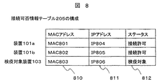
図8に接続可否情報テーブル205の構成を示す。本テーブルはネットワーク104に接続するそれぞれの装置に関するMACアドレス810,IPアドレス811,ステータス812の組からなる。ステータス812が接続許可となっている装置間の通信については、監視装置100は一切干渉しない。ステータス812が検疫対象となっている装置については、当該装置と監視装置100との間の通信のみ可能となるよう監視装置100が処理を行う。本テーブルにエントリーのない装置は接続を許可しない装置である。検疫対象装置103は外部から持ち込まれたコンピュータで、ネットワークとの接続は許可されているが、OS/ウィルス検出ソフトのアップデートが必要であるものとする。検疫対象装置103は他装置との通信のため、ARP要求フレームをブロードキャストで送信する。
FIG. 8 shows the configuration of the connectability information table 205. This table includes a set of a
図3にARP要求フレームを示す。検疫対象装置103がARP要求フレームを送信する場合、送信元MACアドレス301には検疫対象装置103のMACアドレスが、送信元IPアドレス302には検疫対象装置103のIPアドレスが入る。宛て先MACアドレス303には0が入る。宛て先IPアドレスには検疫対象装置103が通信しようとする相手装置のIPアドレスが入る。
FIG. 3 shows an ARP request frame. When the
図4に監視装置100内の接続可否判断処理部204の処理フローを示す。処理401で受信したフレームのプロトコル種別を判断し、ARP以外なら処理を終了する。処理
402で受信したARPの種別を判定し、ARP応答なら処理を終了する。処理403で受信したARP要求の送信元MACアドレスが接続可否情報テーブル205に接続許可装置として登録されているか判断する。登録済みならば処理を終了する。処理404で受信したARP要求の送信元IPアドレスを使用している接続許可装置はあるかを判断する。なければ処理405を、あれば処理406を実施する。処理405では不正装置排除用
ARP応答aをブロードキャスト送信することで、たとえば、装置101aから検疫対象装置103への通信を防ぐ。処理406では不正装置排除用ARP応答bをブロードキャスト送信する。これは検疫対象装置103がすでに他の装置に割り当てられているIPアドレスを使っているケースに対応するためである。すなわち検疫対象装置103がARP要求を送信することによって当該IPアドレス宛ての通信の宛て先が検疫対象装置103宛てに書き換えられてしまうが、不正装置排除用ARP応答bを送信することで、当該
IPアドレス宛ての通信を本来の装置宛てに修正する。処理407は不正装置排除用ARP応答cを検疫対象装置103宛てに送出することで、検疫対象装置103が通信相手としてARP要求を送信した装置のMACアドレスを監視装置100のMACアドレスで上書きすることにより、検疫対象装置からの通信を監視装置100宛てにするためである。
FIG. 4 shows a processing flow of the connection possibility
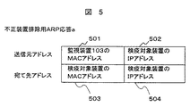
図5に不正装置排除用ARP応答aを示す。送信元MACアドレス501には監視装置100のMACアドレスが、送信元IPアドレス502には検疫対象装置のIPアドレスが、宛て先MACアドレス503には検疫対象装置のMACアドレスが、宛て先IPアドレス504には検疫対象装置のIPアドレスが入る。
FIG. 5 shows an ARP response “a” for excluding unauthorized devices. The
図6に不正装置排除用ARP応答bを示す。送信元MACアドレス601には通信相手のMACアドレスが、送信元IPアドレス602には通信相手のIPアドレスが、宛て先MACアドレス603には検疫対象装置のMACアドレスが、宛て先IPアドレス604には検疫対象装置のIPアドレスが入る。
FIG. 6 shows the ARP response b for unauthorized device exclusion. The
図7に不正装置排除用ARP応答bを示す。送信元MACアドレス701には監視装置100のMACアドレスが、送信元IPアドレス702には通信相手のIPアドレスが、宛て先MACアドレス703には検疫対象装置のMACアドレスが、宛て先IPアドレス704には検疫対象装置のIPアドレスが入る。
FIG. 7 shows the ARP response b for removing the unauthorized device. The
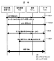
ここで、検疫対象装置103が監視装置100以外の装置、たとえば装置101aと通信する場合の動作を図4に示すフローと図15に示すチャートに従い詳細に説明する。ここでは検疫対象装置103は他の装置とは重複しないIPアドレスを持つものとする。装置101aとの通信を開始する前に、検疫対象装置103はARP要求1501をブロードキャスト送信する。このとき、図3に示す通信相手のIPアドレス304には装置101aのIPアドレスが設定される。
Here, the operation when the
このARP要求に対し、装置101aがARP応答1502を返す。また、ARP要求1501はブロードキャスト送信のため、監視装置100も受信する。監視装置100は図4に示すフローに従いこのフレームに対する処理を行う。すなわち、処理401はARPであるため処理402に進み、処理402は要求であるため処理403に進み、処理403では検疫対象装置103のMACアドレスは接続可否情報テーブル205上に検疫対象として登録されているため処理404に進む。
In response to this ARP request, the
処理404では検疫対象装置103のIPアドレスは他の装置では使われていないため処理405に進む。処理405にて、監視装置100は図15の1503に示す不正装置排除用ARP応答aをブロードキャスト送信する。これにより、ネットワーク104に接続する装置は検疫対象装置103のMACアドレスとして監視装置100のMACアドレスを記憶するので、検疫対象装置103宛ての通信は不可となる。
In
さらに、図4のフローに従い、監視装置100は処理407にて図15の1504に示す不正装置排除用ARP応答cを検疫対象装置103宛てに送出する。これにより、検疫対象装置103は装置101aのMACアドレスとして監視装置100のMACアドレスを記憶するため、装置101a宛ての通信は不可となる。
Further, according to the flow of FIG. 4, the
次に、検疫対象装置103が監視装置100との通信を試みる場合の動作を図4に示すフローと図16に示すチャートに従い詳細に説明する。処理405までの動作は上記で説明した動作と違いはない。続く処理407で、監視装置100は図16の1604に示す不正装置排除用ARP応答cを検疫対象装置103宛てに送出するが、この場合、検疫対象装置103は監視装置100のMACアドレスとして監視装置100のMACアドレスを記憶する。つまり、検疫対象装置103は正しく監視装置100のIPアドレスとMACアドレスの組合せを記憶するので、監視装置100への通信は可能となる。これにより、検疫対象装置103は監視装置100が有するOS/ウィルス検出ソフトのアップデートデータを自装置に転送することが可能となり、OS/ウィルス検出ソフトのアップデートを実施することができる。本アップデートが完了したことを確認した上で、接続可否情報テーブル205上の検疫対象装置103のステータスを検疫対象から接続許可に書き換える。これにより、以後は検疫対象装置103も装置101a〜101bと同等に通信することが可能となる。
Next, the operation when the
以下、実施例2について説明する。 Example 2 will be described below.
図9は本発明の実施例2の構成である。本実施例では、実施例1と異なり、監視装置
100は内部にOS/ウィルス検出ソフトのアップデートデータ保存部203を持たず、替わりにこれらのデータを保持する検疫サーバ102を設置する。検疫サーバ102の役割は、検疫対象装置103からの要求により、OS/ウィルス検出ソフトのアップデートデータを検疫対象装置103へ転送することである。
FIG. 9 shows the configuration of the second embodiment of the present invention. In the present embodiment, unlike the first embodiment, the
図10に実施例2の場合の監視装置100内の接続可否判断処理部204の処理フローを示す。なお、ここでは図4と異なる部分のみ記述してある。処理401〜処理403までは図4と同じである。処理403のあと処理1001にて受信したARP要求の送信元MACアドレスが接続可否情報テーブル205に検疫対象として登録されているかどうかを判定する。登録されていなければ、図4の処理404へと進む。登録されている場合は処理1002へと進む。処理1002では受信したARP要求の宛て先IPアドレスが検疫サーバ102かどうかを判定する。検疫サーバ102以外ならば図4の処理404へと進む。検疫サーバ102宛てならば処理405を実行する。処理405にて不正装置排除用ARP応答aをブロードキャスト送信することで、たとえば、装置101aから検疫対象装置103への通信を防ぐ。ただし、このままでは検疫サーバ102から検疫対象装置103への通信も不可となるため、続く処理1003にて検疫装置アドレス修復用ARP応答を検疫サーバ102宛てに送出する。
FIG. 10 shows a processing flow of the connection possibility
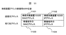
図11に検疫装置アドレス修復用ARP応答を示す。送信元MACアドレス1101には検疫対象装置103のMACアドレスを、送信元IPアドレス1102には検疫対象装置103のIPアドレスを、宛て先MACアドレス1103には修復相手のMACアドレスを、宛て先IPアドレス1104には修復相手のIPアドレスを設定し、修復相手宛てに送信する。
FIG. 11 shows an ARP response for quarantine device address restoration. The
ここで、検疫対象装置103が検疫サーバ102との通信を試みる場合の動作を図10に示すフローと図17に示すチャートに従い詳細に説明する。ここでは検疫対象装置103は他の装置とは重複しないIPアドレスを持つものとする。
Here, the operation in the case where the
検疫サーバ102との通信を開始する前に、検疫対象装置103はARP要求1701をブロードキャスト送信する。このとき、図3のARP要求フレームの通信相手のIPアドレス304には検疫サーバ102のIPアドレスが設定される。このARP要求により、検疫サーバ102はARP応答1702を送信する。また、ARP要求1701はブロードキャスト送信のため、監視装置100も受信し、図10に示すフローに従いこのフレームに対する処理を行う。ただし、処理401〜処理402は実施例1の処理と同じため説明は割愛する。
Before starting communication with the
続く処理403では検疫対象装置103のMACアドレスは接続可否情報テーブル205上に接続許可としては登録されていないため処理1001に進む。処理1001では検疫対象装置103のMACアドレスは接続可否情報テーブル205上に検疫対象として登録されているため処理1002に進む。処理1002では受信したARP要求の宛て先IPアドレスは検疫サーバ102であるため処理405に進む。処理405にて、監視装置
100は不正装置排除用ARP応答a 1703をブロードキャスト送信する。これにより、ネットワーク104に接続する装置は検疫対象装置103のMACアドレスとして監視装置100のMACアドレスを記憶するので、検疫対象装置103宛ての通信は不可となる。続く処理1003で監視装置100は検疫装置アドレス修復用ARP応答1704を検疫サーバ102宛てに送出する。このとき、宛て先MACアドレス1103には検疫サーバ102のMACアドレスが、宛て先IPアドレス1104には検疫サーバ102のIPアドレスが設定される。これにより、検疫サーバ102は検疫対象装置103のMACアドレスとして正しいMACアドレスを記憶するので、検疫サーバ102と検疫対象装置103間の通信が可能となる。よって、検疫対象装置103は検疫サーバ102が有するOS/ウィルス検出ソフトのアップデートデータを自装置に転送することが可能となり、OS/ウィルス検出ソフトのアップデートを実施することができる。これに続く動作は実施例1と同様である。
In the
以下、実施例3について説明する。 Example 3 will be described below.
図12は本発明の実施例3の構成である。本実施例では、実施例2とは異なり、検疫サーバ102はルータ106を介した別ネットワーク105に接続される。ルータ106はこれを通過するIPパケットに対し条件によりフィルタリングする機能を有するものとする。フィルタリング機能そのものは従来から存在する一般的な技術である。
FIG. 12 shows the configuration of the third embodiment of the present invention. In this embodiment, unlike the second embodiment, the
図13にルータ106のフィルタリング設定テーブルの例を示す。フィルタリング設定テーブル1301は、条件となる送信元IPアドレス1302、および、宛て先IPアドレス1303と、その条件を満たすIPパケットに対するアクション1304からなる。本実施例では、ネットワーク104から別ネットワーク105へ向けてルータ106を通過するIPパケットに対し本フィルタを適用する。その設定値は、送信元IPアドレスには検疫対象装置103のIPアドレスを設定する。検疫対象装置が複数ある場合は検疫対象装置103a〜103cのように複数のエントリを作成する。宛て先IPアドレスには検疫サーバ102以外を条件として設定する。アクションは廃棄を設定する。
FIG. 13 shows an example of the filtering setting table of the
また、本実施例では、検疫対象装置のデフォルト・ゲートウェイとしてルータ106のネットワーク104側IPアドレスを設定する。
In this embodiment, the IP address on the
図14に実施例3の監視装置100内の接続可否判断処理部204の処理フローを示す。なお、ここでは図10と異なる部分のみ記述してある。処理401〜処理1001までは図10と同じである。処理1001のあと、処理1402では受信したARP要求の宛て先IPアドレスがルータ106かどうかを判定する。ルータ106以外ならば図4の処理404へと進む。ルータ106宛てならば処理405を実行する。処理405にて不正装置排除用ARP応答をブロードキャスト送信することで、たとえば、装置101aから検疫対象装置103への通信を防ぐ。ただし、このままではルータ106から検疫対象装置103への通信も不可となるため、続く処理1403にて検疫装置アドレス修復用ARP応答をルータ106宛てに送出する。
FIG. 14 illustrates a processing flow of the connection possibility
ここで、検疫対象装置103が検疫サーバ102との通信を試みる場合の動作を図14に示すフローと図18に示すチャートに従い詳細に説明する。ここでは検疫対象装置103は他の装置とは重複しないIPアドレスを持つものとする。検疫サーバ102との通信を開始する前に、検疫対象装置103はARP要求1801をブロードキャスト送信する。このとき、図3のARP要求フレームの通信相手のIPアドレス304には検疫対象装置のデフォルト・ゲートウェイとして設定されたルータ106のIPアドレスが設定される。このARP要求により、ルータ106はARP応答1802を送信する。また、ARP要求1801はブロードキャスト送信のため、監視装置100も受信し、図14に示すフローに従いこのフレームに対する処理を行う。ただし、処理401〜処理1001は実施例2の処理と同じため説明は割愛する。続く処理1402では受信したARP要求の宛て先IPアドレスはルータ106であるため処理405に進む。
Here, the operation when the
処理405にて、監視装置100は示す不正装置排除用ARP応答a 1803をブロードキャスト送信する。これにより、ネットワーク104に接続する装置は検疫対象装置103のMACアドレスとして監視装置100のMACアドレスを記憶するので、検疫対象装置103宛ての通信は不可となる。続く処理1403で監視装置100は検疫装置アドレス修復用ARP応答1804をルータ106宛てに送信する。このとき、宛て先MACアドレス1103にはルータ106のMACアドレスが、宛て先IPアドレス1104にはルータ106のIPアドレスが設定される。これにより、ルータ106は検疫対象装置103のMACアドレスとして正しいMACアドレスを記憶するので、ルータ106と検疫対象装置103間の通信が可能となる。検疫対象装置103から検疫サーバ102宛てのIPパケットがルータ106を通る際、フィルタリング設定テーブル1301と比較される。この例では、送信元IPアドレスが検疫対象装置103、宛て先IPアドレスが検疫サーバであるので、IPパケットはルータ106を通り、別ネットワーク105へ、さらに検疫サーバ102に到達することができる。よって、検疫対象装置103は検疫サーバ102が有するOS/ウィルス検出ソフトのアップデートデータを自装置に転送することが可能となり、OS/ウィルス検出ソフトのアップデートを実施することができる。これに続く動作は実施例2と同様である。
In
次に、検疫対象装置103が別ネットワーク105に接続する検疫サーバ102以外の装置と通信する場合の動作を詳細に説明する。この場合も、前記の検疫対象装置103と検疫サーバ102間の通信同様、ネットワーク104内での検疫対象装置103の通信相手はルータ106のため、たとえ宛て先が検疫サーバ102以外の装置であったとしても、監視装置100は検疫対象装置103とルータ106間の通信を許可する。しかし、ルータ106のフィルタリングテーブル1301との比較において、宛て先IPアドレスが検疫サーバ102以外であるためIPパケットは破棄される。よって、検疫対象装置103が別ネットワーク105に接続する検疫サーバ102以外の装置との通信は不可となる。
Next, the operation when the
本実施例によれば、検疫ネットワーク機能をサポートする専用のスイッチングハブは不要であり、また、一般的なリピータ・ハブを用いても検疫ネットワークを構成できるので、既存のネットワークのハードウェア構成を変更する必要がない。また、DHCP環境においても固定IPアドレス環境においても同様に動作するので、既存ネットワーク環境を変更する必要がない。さらに、すべての端末に対するパーソナル・ファイアウォールなどの専用ソフトウェアのインストールも不要であり、より簡便に検疫ネットワークを実現することができる。 According to this embodiment, a dedicated switching hub that supports the quarantine network function is not required, and a quarantine network can be configured using a general repeater hub, so the hardware configuration of the existing network is changed. There is no need to do. Further, since the same operation is performed in the DHCP environment and the fixed IP address environment, it is not necessary to change the existing network environment. Furthermore, it is not necessary to install dedicated software such as a personal firewall for all terminals, and a quarantine network can be realized more easily.
100…監視装置、102…検疫サーバ、103…検疫対象装置、104…監視装置や検疫対象装置が接続するネットワーク、105…ルータを介した別ネットワーク、106…ルータ、201…フレーム受信処理部、202…フレーム送信処理部、203…OS/ウィルスソフトのアップデートデータ保存部、204…接続可否判断処理部、205…接続可否情報テーブル、206…ARP応答フレーム生成部。
DESCRIPTION OF
Claims (13)
When a frame is transmitted from a quarantine target node, the monitoring node does not interfere with communication between the quarantine target node and a node storing information on the quarantine, and the network addresses of other nodes and higher layers than the network. A network communication method for transmitting a frame so that a combination of corresponding addresses is not included.
Priority Applications (3)
| Application Number | Priority Date | Filing Date | Title |
|---|---|---|---|
| JP2005178697A JP2006352719A (en) | 2005-06-20 | 2005-06-20 | Apparatus, method for monitoring network, network system, network monitoring method and network communication method |
| TW095118494A TW200705887A (en) | 2005-06-20 | 2006-05-24 | Apparatus, method for monitoring network, network system, network monitoring method and network communication method |
| CN200610094656XA CN1905495B (en) | 2005-06-20 | 2006-06-20 | Network monitoring device, network monitoring method, network system and network communication method |
Applications Claiming Priority (1)
| Application Number | Priority Date | Filing Date | Title |
|---|---|---|---|
| JP2005178697A JP2006352719A (en) | 2005-06-20 | 2005-06-20 | Apparatus, method for monitoring network, network system, network monitoring method and network communication method |
Publications (1)
| Publication Number | Publication Date |
|---|---|
| JP2006352719A true JP2006352719A (en) | 2006-12-28 |
Family
ID=37648040
Family Applications (1)
| Application Number | Title | Priority Date | Filing Date |
|---|---|---|---|
| JP2005178697A Pending JP2006352719A (en) | 2005-06-20 | 2005-06-20 | Apparatus, method for monitoring network, network system, network monitoring method and network communication method |
Country Status (3)
| Country | Link |
|---|---|
| JP (1) | JP2006352719A (en) |
| CN (1) | CN1905495B (en) |
| TW (1) | TW200705887A (en) |
Cited By (5)
| Publication number | Priority date | Publication date | Assignee | Title |
|---|---|---|---|---|
| JP2009059224A (en) * | 2007-08-31 | 2009-03-19 | Toshiba Corp | Server apparatus and control method thereof |
| JP2009100226A (en) * | 2007-10-16 | 2009-05-07 | Toshiba Corp | Communication guidance device, communication control server device, and program |
| JP2011130016A (en) * | 2009-12-15 | 2011-06-30 | Ntt Communications Kk | Access control system, access control method, and program |
| JP2011205560A (en) * | 2010-03-26 | 2011-10-13 | Nec Corp | Unauthorized connection preventing apparatus and program |
| JP2011217016A (en) * | 2010-03-31 | 2011-10-27 | Nec Corp | Unauthorized connection prevention apparatus and program |
Families Citing this family (2)
| Publication number | Priority date | Publication date | Assignee | Title |
|---|---|---|---|---|
| JP5245837B2 (en) | 2009-01-06 | 2013-07-24 | 富士ゼロックス株式会社 | Terminal device, relay device, and program |
| TWI474668B (en) * | 2012-11-26 | 2015-02-21 | Method for distinguishing and blocking off network node |
Citations (3)
| Publication number | Priority date | Publication date | Assignee | Title |
|---|---|---|---|---|
| JP2001016260A (en) * | 1999-06-30 | 2001-01-19 | Mitsubishi Electric Corp | Data communication system |
| JP2002084306A (en) * | 2000-06-29 | 2002-03-22 | Hitachi Ltd | Packet communication apparatus and network system |
| JP2004185498A (en) * | 2002-12-05 | 2004-07-02 | Matsushita Electric Ind Co Ltd | Access control unit |
Family Cites Families (1)
| Publication number | Priority date | Publication date | Assignee | Title |
|---|---|---|---|---|
| CN1232072C (en) * | 2002-05-10 | 2005-12-14 | 华为技术有限公司 | Communication method for sharing one subnet section of protocol between network by multiple virtual local networks |
-
2005
- 2005-06-20 JP JP2005178697A patent/JP2006352719A/en active Pending
-
2006
- 2006-05-24 TW TW095118494A patent/TW200705887A/en not_active IP Right Cessation
- 2006-06-20 CN CN200610094656XA patent/CN1905495B/en not_active Expired - Fee Related
Patent Citations (3)
| Publication number | Priority date | Publication date | Assignee | Title |
|---|---|---|---|---|
| JP2001016260A (en) * | 1999-06-30 | 2001-01-19 | Mitsubishi Electric Corp | Data communication system |
| JP2002084306A (en) * | 2000-06-29 | 2002-03-22 | Hitachi Ltd | Packet communication apparatus and network system |
| JP2004185498A (en) * | 2002-12-05 | 2004-07-02 | Matsushita Electric Ind Co Ltd | Access control unit |
Non-Patent Citations (1)
| Title |
|---|
| CSND200401409004, 実森仁志・榊原康, ""内部崩壊"する社内ネット 5つのシステム化で食い止めろ", 日経システム構築 2004年3月号, 20040226, No.131, pp.98−109, JP, 日経BP社 * |
Cited By (5)
| Publication number | Priority date | Publication date | Assignee | Title |
|---|---|---|---|---|
| JP2009059224A (en) * | 2007-08-31 | 2009-03-19 | Toshiba Corp | Server apparatus and control method thereof |
| JP2009100226A (en) * | 2007-10-16 | 2009-05-07 | Toshiba Corp | Communication guidance device, communication control server device, and program |
| JP2011130016A (en) * | 2009-12-15 | 2011-06-30 | Ntt Communications Kk | Access control system, access control method, and program |
| JP2011205560A (en) * | 2010-03-26 | 2011-10-13 | Nec Corp | Unauthorized connection preventing apparatus and program |
| JP2011217016A (en) * | 2010-03-31 | 2011-10-27 | Nec Corp | Unauthorized connection prevention apparatus and program |
Also Published As
| Publication number | Publication date |
|---|---|
| TW200705887A (en) | 2007-02-01 |
| CN1905495A (en) | 2007-01-31 |
| CN1905495B (en) | 2011-12-21 |
| TWI315139B (en) | 2009-09-21 |
Similar Documents
| Publication | Publication Date | Title |
|---|---|---|
| JP4664143B2 (en) | Packet transfer apparatus, communication network, and packet transfer method | |
| US7870603B2 (en) | Method and apparatus for automatic filter generation and maintenance | |
| JP5662133B2 (en) | Method and system for resolving conflict between IPSEC and IPV6 neighbor requests | |
| JP2006262141A (en) | Ip address applying method, vlan changing device, vlan changing system and quarantine processing system | |
| JP4487150B2 (en) | Communication apparatus, firewall control method, and firewall control program | |
| US8646033B2 (en) | Packet relay apparatus | |
| WO2005036831A1 (en) | Frame relay device | |
| US9686279B2 (en) | Method and system for providing GPS location embedded in an IPv6 address using neighbor discovery | |
| US20200036682A1 (en) | Communication apparatus and communication system | |
| JP4920878B2 (en) | Authentication system, network line concentrator, authentication method used therefor, and program thereof | |
| JP2006352719A (en) | Apparatus, method for monitoring network, network system, network monitoring method and network communication method | |
| US8601271B2 (en) | Method and system for power management using ICMPV6 options | |
| JP2008271242A (en) | Network monitor, program for monitoring network, and network monitor system | |
| JP4895793B2 (en) | Network monitoring apparatus and network monitoring method | |
| JP4750750B2 (en) | Packet transfer system and packet transfer method | |
| WO2017219777A1 (en) | Packet processing method and device | |
| US20170289099A1 (en) | Method and Device for Managing Internet Protocol Version 6 Address, and Terminal | |
| JP3616571B2 (en) | Address resolution method for Internet relay connection | |
| JP4408831B2 (en) | Network system and communication control method thereof | |
| JP5413940B2 (en) | Thin client network, thin client, unauthorized connection prevention device, operation method thereof, and recording medium | |
| JP2005136629A (en) | Network system | |
| JP2011124774A (en) | Network monitoring device, and network monitoring method | |
| JP2006287704A (en) | Switching hub | |
| JP2012199758A (en) | Quarantine management device, quarantine system, quarantine management method, and program | |
| JP2022054640A (en) | Network controller and program |
Legal Events
| Date | Code | Title | Description |
|---|---|---|---|
| A621 | Written request for application examination |
Free format text: JAPANESE INTERMEDIATE CODE: A621 Effective date: 20080124 |
|
| A977 | Report on retrieval |
Free format text: JAPANESE INTERMEDIATE CODE: A971007 Effective date: 20100524 |
|
| A131 | Notification of reasons for refusal |
Free format text: JAPANESE INTERMEDIATE CODE: A131 Effective date: 20100615 |
|
| A521 | Written amendment |
Free format text: JAPANESE INTERMEDIATE CODE: A523 Effective date: 20100810 |
|
| A02 | Decision of refusal |
Free format text: JAPANESE INTERMEDIATE CODE: A02 Effective date: 20100914 |