JP2006347630A - Closing strip for sheet or bag, and sheet or bag obtained using it - Google Patents
Closing strip for sheet or bag, and sheet or bag obtained using it Download PDFInfo
- Publication number
- JP2006347630A JP2006347630A JP2006128443A JP2006128443A JP2006347630A JP 2006347630 A JP2006347630 A JP 2006347630A JP 2006128443 A JP2006128443 A JP 2006128443A JP 2006128443 A JP2006128443 A JP 2006128443A JP 2006347630 A JP2006347630 A JP 2006347630A
- Authority
- JP
- Japan
- Prior art keywords
- assembly according
- assembly
- strip
- cut
- fastening
- Prior art date
- Legal status (The legal status is an assumption and is not a legal conclusion. Google has not performed a legal analysis and makes no representation as to the accuracy of the status listed.)
- Pending
Links
Images


Classifications
-
- B—PERFORMING OPERATIONS; TRANSPORTING
- B65—CONVEYING; PACKING; STORING; HANDLING THIN OR FILAMENTARY MATERIAL
- B65D—CONTAINERS FOR STORAGE OR TRANSPORT OF ARTICLES OR MATERIALS, e.g. BAGS, BARRELS, BOTTLES, BOXES, CANS, CARTONS, CRATES, DRUMS, JARS, TANKS, HOPPERS, FORWARDING CONTAINERS; ACCESSORIES, CLOSURES, OR FITTINGS THEREFOR; PACKAGING ELEMENTS; PACKAGES
- B65D33/00—Details of, or accessories for, sacks or bags
- B65D33/16—End- or aperture-closing arrangements or devices
- B65D33/25—Riveting; Dovetailing; Screwing; using press buttons or slide fasteners
- B65D33/2508—Riveting; Dovetailing; Screwing; using press buttons or slide fasteners using slide fasteners with interlocking members having a substantially uniform section throughout the length of the fastener; Sliders therefor
- B65D33/2541—Riveting; Dovetailing; Screwing; using press buttons or slide fasteners using slide fasteners with interlocking members having a substantially uniform section throughout the length of the fastener; Sliders therefor characterised by the slide fastener, e.g. adapted to interlock with a sheet between the interlocking members having sections of particular shape
-
- Y—GENERAL TAGGING OF NEW TECHNOLOGICAL DEVELOPMENTS; GENERAL TAGGING OF CROSS-SECTIONAL TECHNOLOGIES SPANNING OVER SEVERAL SECTIONS OF THE IPC; TECHNICAL SUBJECTS COVERED BY FORMER USPC CROSS-REFERENCE ART COLLECTIONS [XRACs] AND DIGESTS
- Y10—TECHNICAL SUBJECTS COVERED BY FORMER USPC
- Y10T—TECHNICAL SUBJECTS COVERED BY FORMER US CLASSIFICATION
- Y10T24/00—Buckles, buttons, clasps, etc.
- Y10T24/25—Zipper or required component thereof
- Y10T24/2532—Zipper or required component thereof having interlocking surface with continuous cross section
- Y10T24/2534—Opposed interlocking surface having dissimilar cross section
Abstract
Description
本発明は、締結又は閉鎖アッセンブリが取り付けられたシート又は袋の分野に関する。 The present invention relates to the field of seats or bags with fastening or closure assemblies attached.
随意に連続して何回でも開閉できるようにその口部にアッセンブリが取り付けられた袋として、例えば日常用途(あくまでも一例でありこれに限定されるものではない)で用いられるバッグや小さな袋のようなものが多数知られている。 As a bag with an assembly attached to its mouth so that it can be opened and closed any number of times continuously, for example, a bag used for daily use (not limited to this example) or a small bag Many things are known.
このような閉鎖アッセンブリとしては特に、袋の口部にて互いに対向する相補的な雄型又は雌型の要素をそれぞれ担持する二つの支持ウェブを備えたものが知られている。機能的に同等の閉鎖アッセンブリとしては、袋の口部にて互いに対向するように位置付けられたウェブ上のフックであって、互いに引っかけることにより両者を固定するものも知られている。 Such closure assemblies are known in particular with two support webs each carrying complementary male or female elements facing each other at the mouth of the bag. As a functionally equivalent closing assembly, there is also known a hook on the web positioned so as to face each other at the mouth of the bag, and the two are fixed by being hooked to each other.
他の分野、特に商品陳列や包装用材料のような分野では、締結(ファスナ)アッセンブリが取り付けられたシートして、他のシート又は関連する支持体の上に設けられた相補的な締結アッセンブリないし手段と協働するように設計されたものが知られている。 In other fields, particularly in fields such as merchandise display and packaging materials, a sheet with a fastening assembly attached thereto and a complementary fastening assembly provided on the other sheet or associated support. Those designed to cooperate with the means are known.
出願人は、特定の状況において、従来の締結又は閉鎖アッセンブリが十分な満足感を与えるものでないことを見出した。 Applicants have found that in certain circumstances, conventional fastening or closure assemblies do not provide sufficient satisfaction.
このことは特に、ポリオレフィン、主としてポリエチレン又はポリプロピレンからなる締結又は閉鎖アッセンブリに当てはまる。押出成形がなされた後で、かつ、シート又は袋を作り上げるためにフィルムに固定される前の時点においては、このようなアッセンブリは一般に、保管用の円形のリールに巻き取られている。残念なことに、このような用途で用いられるポリマーは、変形状態に関して弾性記憶(elastic memory)を持っており、時が経つと、各種の相を経て、異なった種類の結晶の形態に再結晶化する。 This is particularly true for fastening or closure assemblies made of polyolefins, primarily polyethylene or polypropylene. Such assemblies are typically wound on a circular reel for storage at a point after extrusion and before being secured to the film to make up a sheet or bag. Unfortunately, the polymers used in such applications have elastic memory with respect to the deformation state and, over time, recrystallize into different types of crystals through various phases. Turn into.
このことは、高いレベルの内部応力をもたらすこととなり、以上のようにして円形のリールに保管されているアッセンブリに対して、ある種のゆがみやねじれが引き起こされる。 This results in a high level of internal stress, which causes some kind of distortion and twist on the assembly stored on the circular reel as described above.
このような湾曲は、締結又は閉鎖アッセンブリをフィルム(シート又は袋を構成することとなるもの)の上に固定するプロセスを実施する際に、非常に厄介なものとなる。アッセンブリのこのようなゆがみやねじれのために、締結又は閉鎖アッセンブリがリール上の保管状態から巻き出された後に正確に直線状に保たれることを保証することが非常に困難であることが理解されるであろう。その結果、使用状態において、このような相補的な締結又は閉鎖アッセンブリを正しい位置に配置することがしばしば困難となり、従って、袋用の適切な閉鎖具や満足のいくシートアッセンブリを得ることが困難となる。また、締結又は閉鎖アッセンブリがフィルムの進行方向を横切って延びる方向に搬送される際には特に、アッセンブリを固定する前に、袋又はシートを作り上げるためのフィルム上にアッセンブリがくるようにアッセンブリを案内することがしばしば必要となる。この場合、締結又は閉鎖アッセンブリが好ましくない形でゆがんでいると、それらがガイドから逃げてしまうことが判明した。 Such curvature becomes very cumbersome when performing the process of securing the fastening or closing assembly onto the film (which will constitute a sheet or bag). It is understood that due to such warping and twisting of the assembly, it is very difficult to ensure that the fastening or closing assembly is kept in a straight line after being unwound from storage on the reel. Will be done. As a result, in use, it is often difficult to place such complementary fastening or closure assemblies in the correct position, thus making it difficult to obtain a suitable closure for a bag and a satisfactory seat assembly. Become. Also, especially when the fastening or closing assembly is transported in a direction extending across the direction of travel of the film, the assembly is guided so that the assembly is on the film for making up the bag or sheet prior to securing the assembly. It is often necessary to do. In this case, it has been found that if the fastening or closure assembly is distorted in an undesirable manner, they will escape from the guide.
各種の解決手段が既に提案されており、その一つは特に、このような閉鎖アッセンブリに対して、保管中に与えられたのとは逆の方向へのねじれを与えることにより、閉鎖アッセンブリの記憶効果を取り除く、というものである。この点については、特に特許文献1を参照されたい。
しかしながら、このような解決手段は十分に満足できるものではない。 However, such a solution is not fully satisfactory.
本発明の目的は、このような状況を改良することにある。 The object of the present invention is to improve such a situation.
このような目的のため、本発明は、シート又は包装用の袋の口部に取り付けられる締結又は閉鎖アッセンブリを提供する。この締結又は閉鎖アッセンブリは、支持ウェブと、この支持ウェブにより担持された締結又は閉鎖要素とにより形成された、少なくとも一つの締結又は閉鎖ストリップを備えている。このような締結又は閉鎖アッセンブリは、ストリップの支持ウェブの幅方向の一部を占める、連続的に配置された切り口を有し、これらの切り口は、締結又は閉鎖要素の外側に位置するとともに、アッセンブリの長さ方向に亘って配置され、アッセンブリのゆがみや湾曲、ねじれの影響を抑えるように構成されていることを特徴とする。 To this end, the present invention provides a fastening or closure assembly that is attached to the mouth of a sheet or packaging bag. The fastening or closure assembly comprises at least one fastening or closure strip formed by a support web and a fastening or closure element carried by the support web. Such fastening or closing assemblies have continuously arranged cuts that occupy a part of the width direction of the support web of the strip, these cuts being located outside the fastening or closing elements and the assembly. It is arranged over the length direction, and is configured to suppress the influence of distortion, bending and twisting of the assembly.
本出願人は、締結又は閉鎖アッセンブリにおいて、上述したような切り口を、支持ウェブのうち締結又は閉鎖要素の外側の全体に亘って形成することにより、上述したようなゆがみや湾曲、ねじれが除去される、ということを見出した。 Applicants have found that in a fastening or closing assembly, the above-described cuts are formed over the entire outside of the fastening or closing element of the support web to eliminate the above-mentioned distortion, curvature and twist. I found out.
このようにしてアッセンブリに施される切り口の領域は、応力を緩和させ、また少なくとも、応力が伝達されることを防止することができる。これにより、上述したような従来技術の分野においてアッセンブリ上で見つけられる、ゆがみ等が除去される。 In this way, the cut area applied to the assembly can relieve stress and at least prevent stress from being transmitted. This eliminates distortions and the like found on the assembly in the prior art field as described above.
本発明に係る非限定的な実施形態において、上述した連続的に配置される切り口は、前記アッセンブリを支持する各々のウェブの縁の一つ(すなわち狭い縁)に対して開口している。しかしながら、変形例において、連続的に配置される切り口が、前記アッセンブリを支持する各々のウェブの中間の領域(すなわち二つの側縁の間の領域)に亘って、側縁に対して開口することなく、形成されていてもよい。 In a non-limiting embodiment according to the present invention, the continuously arranged cuts described above are open to one of the edges (ie, the narrow edge) of each web that supports the assembly. However, in a variant, the continuously arranged cuts open to the side edges over the middle area of each web supporting the assembly (ie the area between the two side edges). Alternatively, it may be formed.
本発明の別の有利な特徴によれば、連続的に配置される切り口は、袋のピッチで形成されているとよい。しかしながら、変形例としては、上述したような袋を形成するフィルム上にストリップを固定する固定手段が、切り口の近傍において前記アッセンブリと前記フィルムとの間の良好な接触を保証する限り、連続的に配置された切り口が、袋のピッチと非常に異なったピッチで形成されていてもよい。 According to another advantageous feature of the invention, the continuously arranged cuts may be formed with a bag pitch. However, as a variant, as long as the fixing means for fixing the strip on the film forming the bag as described above ensures good contact between the assembly and the film in the vicinity of the cut, The arranged cut ends may be formed at a pitch very different from the pitch of the bag.
本発明はまた、上述したような締結又は閉鎖アッセンブリを用いて得られたシート又は袋を提供する。 The present invention also provides a sheet or bag obtained using a fastening or closure assembly as described above.
本発明の他の特徴、目的及び利点は、非限定的な例として与えられた添付図面を参照しながら以下の詳細な説明を読むことにより理解されるであろう。 Other features, objects and advantages of the present invention will be understood upon reading the following detailed description with reference to the accompanying drawings, given by way of non-limiting example.
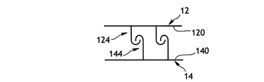
添付の図1は、包装用の袋の口部やシートに取り付けられるのに適した、本発明に係る締結又は閉鎖アッセンブリ10を示している。締結又は閉鎖アッセンブリ10は、二つの相補的なストリップ12、14により構成されており、これらのストリップ12、14には、支持ウェブ120、140に担持された、例えば相補的な雄型又は雌型の要素122、142、又は相補的なフック124、144が設けられている。
FIG. 1 of the accompanying drawings shows a fastening or
添付の図1から分かるように、本発明によれば、二つのストリップ12、14にはそれぞれ、ウェブ120、140のうちファスナ(締結)要素124、144の外側に切り口13、15が設けられている。これらの切り口13、15は袋と同一のピッチpで形成されているとよい。すなわち、二つの切り口13、15の間の距離p(ストリップ12、14に沿った距離)は、この例では、ストリップが固定されることとなる袋の口部の幅に等しい。しかしながら、変形例においては、上述したとおり、上述したような袋を形成するフィルム上にストリップを固定する固定手段が、切り口の近傍においてストリップ12、14とフィルムとの間の良好な接触を保証する限り(すなわち、固定手段が、ストリップ12、14がこれらの位置で引き離されるのを避けるように作用する限り)、連続的に配置された切り口13、15が、袋のピッチと非常に異なったピッチで形成されていてもよい。
As can be seen from the attached FIG. 1, according to the present invention, the two
図1に示す例では、切り口13、15はその輪郭が矩形状をなしている。しかしながら、このような構成は本質的なものではない。
In the example shown in FIG. 1, the
また、図1及び図2に示す構成では、切り口13、15は全て、ストリップ12、14の同一の縁に対して開口している。これらの切り口は、この縁と、ファスナ要素124、144に隣接する領域との間に亘って延びており、ファスナ要素124、144の下方には延びていない。
Further, in the configuration shown in FIGS. 1 and 2, the
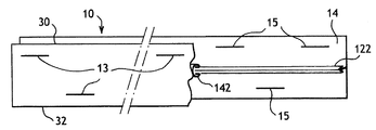
しかしながら、これは一例であり、図8には変形例の構成が示されている。図8において、切り口13、15は、ストリップのウェブの中間の領域に形成されている。すなわち、切り口13、15は、ストリップの二つの側縁30、32の間の領域に形成されており、これらの縁のいずれに対しても開口しておらず、ファスナ要素122、142の下方にも延びていない。
However, this is an example, and FIG. 8 shows a configuration of a modified example. In FIG. 8,
非限定的な例についてのものであるが、図1に示す例において、切り口13、15はそれらの高さhよりも大きな幅l(図ではeに相当)を持っている。
As for a non-limiting example, in the example shown in FIG. 1, the
添付の図2は、本発明に係る閉鎖アッセンブリの変形例を示している。この変形例は、ウェブ120、140に形成された切り口13、15が、その幅において非常に狭く、かつ、ストリップ12、14の縁に対して垂直に延びる狭い切欠き(ノッチ)に相当している、という点で、図1に示す第1の実施形態と異なっている。それが適切であるならば、図2に示す切欠き13、15は、何ら材料を除去することなく形成される、単なる切り込みのようなものとして構成されていてもよい。
The attached FIG. 2 shows a variant of the closure assembly according to the invention. This variant corresponds to a narrow notch in which the
添付の図3は、既存の閉鎖ストリップの例を示しており、この例において、ストリップ12、14はそれぞれ、ウェブ120、140を備えている。ウェブ120、140のうちの一方は雄型の要素122を担持し、他方は相補的な雌型の要素142を担持する。このような閉鎖ストリップは当業者に良く知られたものであるので、ここでは、単純に実例のみを示し、より詳細な説明はしない。
The attached FIG. 3 shows an example of an existing closure strip, in which the
図4は、閉鎖ストリップの別の例を示しており、この例において、二つのストリップ12、14はそれぞれ、符号124、144が付された相補的なフックの形態の要素を担持するウェブ120、140を備えている。この例においても、このような閉鎖アッセンブリは当業者に良く知られたものであるので、単純に実例のみを示し、より詳細な説明はしない。
FIG. 4 shows another example of a closure strip, in which two
図5及び図6は、図3及び図4にそれぞれ類似した二つの変形例を示しており、これらの例において、ウェブ120はファスナ要素122、142の一方の側のみに延びている。このような変形例もまた、当業者に良く知られたものであるので、より詳細な説明はしない。
FIGS. 5 and 6 show two variations similar to FIGS. 3 and 4, respectively, in which the
最後に、図7においては、上述した閉鎖アッセンブリに取り付けられるのに適したスライダーの基本構造の断面が示されている。スライダーとしてのカーソル20は、二つの側壁24、26と一つの中央低壁28とを担持する底壁22を備えている。低壁28及び側壁24、26は、それらの間に二つの非平行な通路27、29を画成している。通路27、29は、スライダーの一方の軸方向端部へ向けて収束している。通路27、29は、ストリップ12、14のそれぞれを受け入れるように設計されている。当業者であれば従って、スライダー20が閉鎖ストリップの一方の軸方向端部へ向けて移動する際に、それらが切り離され、その結果として袋が開く、ということが容易に理解されるであろう。これに対し、スライダーが閉鎖ストリップの第二の端部へ向けて移動した際には、それらが一緒になるように移動し、その結果として袋が閉まる。
Finally, in FIG. 7, a cross-section of the basic structure of the slider suitable for being attached to the closure assembly described above is shown. The
本発明に係る切り口13、15を有する閉鎖ストリップ12、14、及びまた(必要であれば)スライダー20は、包装用の袋やシートを作るのに適した任意の種類のフィルム、特に(それに限定されるものではないが)プラスチック材料や複合材料からなるフィルムに関連付けられる。同様に、締結又は閉鎖ストリップ12、14は、任意の適切な手段、好ましくは熱シーリングによりフィルムに固定されてもよい。
The closure strips 12, 14 with
本発明においては、切り口13、15の高さhは、好ましくは、閉鎖ストリップ12、14の高さh0に対して1/3から1/10の範囲にあるとよい。
In the present invention, the height h of the
当然に、本発明は、上述した特定の実施形態に限定されるものではなく、本発明の精神の範囲内にある任意の変形例に及ぶものである。 Of course, the present invention is not limited to the specific embodiments described above, but extends to any variation that is within the spirit of the invention.
図1ないし図8に示す実施形態において、切り口13、15は閉鎖ストリップの縁30、32に対して垂直に延びている。
In the embodiment shown in FIGS. 1 to 8, the
図9は、切り口13、15が縁30、32に対して斜めになっている、変形例の構成を示している。
FIG. 9 shows a modified configuration in which the cut edges 13 and 15 are inclined with respect to the
より詳細には、図9において、切り口13、15は閉鎖ストリップの縁30の一つに対して開口している。図9に示す切り口の斜めの配置はまた、上述したような、切り口が閉鎖ストリップのいずれの縁に対しても開口しておらず、かつ、縁の間にて延びるような場合(図8に模式的に示す場合)にも適用することができる。
More particularly, in FIG. 9, the
好ましくは、本発明において、図9に示す斜めの切り口13、15は、ストリップの縁30に対して約30°〜60°の角度αで傾斜している。
Preferably, in the present invention, the oblique cuts 13, 15 shown in FIG. 9 are inclined at an angle α of about 30 ° to 60 ° with respect to the
より詳細には、図9に示す閉鎖ストリップは、次のような態様で、図9にて矢印Dで示す方向に移動するように構成されている。すなわち、静止状態でかつ閉鎖ストリップが移動するにつれて相対的に移動するガイド又は支持体は、初期の段階では、閉鎖ストリップの内側に位置する切り口13、15の端部130に係合し、最終的には、縁30に対して開口する切り口の自由端部132に係合する。その結果、閉鎖ストリップは、上述したようなガイド又は支持体を位置付ける際に、鋭角的でない鈍角的な前縁のみを提供することとなり、閉鎖ストリップとそれに関連するガイド又は支持体との間で引っ掛かりないし食い込みが生じる恐れを回避する。
More specifically, the closing strip shown in FIG. 9 is configured to move in the direction indicated by arrow D in FIG. 9 in the following manner. That is, a guide or support that is stationary and moves relatively as the closure strip moves, initially engages the
図9に示す切り口の斜めの配置は従って、袋を作るためのフィルム上に留め付けられるべくガイド内で閉鎖ストリップが移動するような場合に特に有利である。 The diagonal arrangement of the cuts shown in FIG. 9 is therefore particularly advantageous when the closure strip moves within the guide to be fastened on the film for making the bag.
図9に示す変形例において、切り口13、15は平行な縁を有しており、適切であれば、上述したように、何ら材料を除去することなく形成されていてもよい。
In the variation shown in FIG. 9, the
図10は、切り口13、15が、互いに平行でない縁134、135、154、155を提供するような、変形例を示している。切り口13、15は、それらの開口側の縁が閉鎖ストリップの縁30の開口部へ向くことで、V字型の形状をなしている。図10は、縁30に垂直な平面に関して対称的である切り口13、15を示している。しかしながら、このような配置は本質的なものではなく、切り口13、15は、縁30に垂直な平面に対して非対称的であってもよい。
FIG. 10 shows a variation in which the
切り口13、15は、閉鎖ストリップの縁30に対して30°〜60°の範囲にある角度で各々傾斜した直線的な縁134、135、154、155により画成されている。このような配置は、閉鎖ストリップが、静止状態にある支持体又はガイドに対して、引っ掛かりや食い込みといった何らのリスクもなく、いずれの方向にも移動することができる、という点で有利である。
The
図11は、切り口13、15が縁30、32に対して略平行であるような、他の変形例の構成を示している。図11において、同一のストリップ内にある切り口13、15は全て一列に並んでいる。
FIG. 11 shows a configuration of another modified example in which the cut edges 13 and 15 are substantially parallel to the
図12は、切り口13、15がストリップの縁30、32に対して略平行でありながら、それらの全てが一列には並んでいない、他の変形例の構成を示している。
FIG. 12 shows another variation of the configuration in which the
10 締結又は閉鎖アッセンブリ
12、14 締結又は閉鎖ストリップ
13、15 切り口
20 スライダー(カーソル)
22 底壁
24、26 側壁
27、29 通路
28 中央低壁
30、32 側縁
120、140 支持ウェブ
122、142 ファスナ要素
124、144 フック
130、132 端部
134、135、154、155 側縁
10 Fastening or closing
22
Claims (29)
前記ストリップの前記支持ウェブ(120、140)の幅方向の一部を占める、連続的に配置された切り口(13、15)を有し、これらの切り口(13、15)は、前記締結又は閉鎖要素(124、144)の外側に位置するとともに、前記アッセンブリの長さ方向に亘って配置され、前記アッセンブリのゆがみや湾曲、ねじれの影響を抑えるように構成されていることを特徴とする、締結又は閉鎖アッセンブリ。 A fastening or closure assembly attached to the mouth of a sheet or packaging bag, comprising a support web (120, 140) and a fastening or closure element (124, 144) carried by the support web (120, 140) In a fastening or closing assembly comprising at least one fastening or closing strip (12, 14) formed by
Having continuously arranged cuts (13, 15) occupying a part of the width direction of the support web (120, 140) of the strip, these cuts (13, 15) being fastened or closed Fastening, characterized in that it is located outside the elements (124, 144) and is arranged over the length of the assembly to limit the effects of distortion, bending and twisting of the assembly Or a closed assembly.
Applications Claiming Priority (1)
| Application Number | Priority Date | Filing Date | Title |
|---|---|---|---|
| FR0506151A FR2881113B1 (en) | 2005-01-25 | 2005-06-17 | CLOSURE PROFILES FOR SACHET OR SHEET AND SACHET OBTAINED |
Publications (1)
| Publication Number | Publication Date |
|---|---|
| JP2006347630A true JP2006347630A (en) | 2006-12-28 |
Family
ID=37571898
Family Applications (1)
| Application Number | Title | Priority Date | Filing Date |
|---|---|---|---|
| JP2006128443A Pending JP2006347630A (en) | 2005-06-17 | 2006-05-02 | Closing strip for sheet or bag, and sheet or bag obtained using it |
Country Status (3)
| Country | Link |
|---|---|
| US (1) | US7604407B2 (en) |
| JP (1) | JP2006347630A (en) |
| BR (1) | BRPI0601662A (en) |
Families Citing this family (3)
| Publication number | Priority date | Publication date | Assignee | Title |
|---|---|---|---|---|
| US20090129708A1 (en) * | 2005-09-13 | 2009-05-21 | Juichi Kasai | Plastic zipper having preventing function against unfairly unsealing, and the manufacturing method and manufacturing appartus thereof |
| US7681732B2 (en) | 2008-01-11 | 2010-03-23 | Cryovac, Inc. | Laminated lidstock |
| US7781859B2 (en) * | 2008-03-24 | 2010-08-24 | Taiwan Semiconductor Manufacturing Company, Ltd. | Schottky diode structures having deep wells for improving breakdown voltages |
Citations (2)
| Publication number | Priority date | Publication date | Assignee | Title |
|---|---|---|---|---|
| US5722128A (en) * | 1996-11-04 | 1998-03-03 | Dow Brands Inc. | Fastener assembly with slider providing tactile and/or audible feedback |
| JP2001270012A (en) * | 1999-12-02 | 2001-10-02 | Reynolds Consumer Prod Inc | Method for manufacturing reclosable package having slider device |
Family Cites Families (5)
| Publication number | Priority date | Publication date | Assignee | Title |
|---|---|---|---|---|
| US4246288A (en) * | 1979-08-09 | 1981-01-20 | W. R. Grace & Co. | Reclosable package |
| US4655862A (en) * | 1984-01-30 | 1987-04-07 | Minigrip, Incorporated | Method of and means for making reclosable bags and method therefor |
| US5063639A (en) * | 1990-02-23 | 1991-11-12 | Zip-Pak Incorporated | Zippered closure for packages |
| US6955465B2 (en) * | 2002-04-15 | 2005-10-18 | Illinois Tool Works Inc. | Powder-resistant flexible zipper for reclosable packaging |
| US20060171610A1 (en) * | 2005-01-31 | 2006-08-03 | Buchman James E | Internal gripping slider and method |
-
2006
- 2006-04-28 BR BRPI0601662-6A patent/BRPI0601662A/en not_active Application Discontinuation
- 2006-04-28 US US11/413,351 patent/US7604407B2/en active Active
- 2006-05-02 JP JP2006128443A patent/JP2006347630A/en active Pending
Patent Citations (2)
| Publication number | Priority date | Publication date | Assignee | Title |
|---|---|---|---|---|
| US5722128A (en) * | 1996-11-04 | 1998-03-03 | Dow Brands Inc. | Fastener assembly with slider providing tactile and/or audible feedback |
| JP2001270012A (en) * | 1999-12-02 | 2001-10-02 | Reynolds Consumer Prod Inc | Method for manufacturing reclosable package having slider device |
Also Published As
| Publication number | Publication date |
|---|---|
| US20060282997A1 (en) | 2006-12-21 |
| BRPI0601662A (en) | 2007-02-13 |
| US7604407B2 (en) | 2009-10-20 |
Similar Documents
| Publication | Publication Date | Title |
|---|---|---|
| US9102423B2 (en) | Flip-lock instant closure mechanism and method | |
| US20060159372A1 (en) | Zipper for transverse direction front panel pouch | |
| KR20180091106A (en) | Roll of flexible glass and method for rolling | |
| JP2006347630A (en) | Closing strip for sheet or bag, and sheet or bag obtained using it | |
| JP2018000919A (en) | Surface bonding fastener | |
| US8955774B2 (en) | Water-drip hose | |
| US10011397B2 (en) | Enhancements to spaced multi-rib closure | |
| US20090017172A1 (en) | Reclosable animal feed container | |
| JP2000342081A (en) | Restraining member for film-fixing material | |
| EP1683730B1 (en) | Bag zipper closures | |
| EP3725182A1 (en) | Hair holding tool and method for manufacturing same | |
| JP6236581B1 (en) | Wind nail corrector | |
| CN106617519A (en) | Zipper tooth tape and zipper tape and zipper using zipper tooth tape | |
| JP5219673B2 (en) | Chain terminal | |
| JP3841765B2 (en) | Retractable screen device | |
| JP6211997B2 (en) | Folding container | |
| JPH0676839B2 (en) | Synthetic resin pipe | |
| JP6541977B2 (en) | Rolled-in container box and wound-in container | |
| ITTO20100587A1 (en) | PRINTER WITH RETRACTABLE LID | |
| JP7258689B2 (en) | screen device | |
| US6282757B1 (en) | Flexible closure | |
| FR2881112A1 (en) | Hooking or fastening assembly for e.g. pouch package, has hooking or fastening section formed of voile and hooking and fastening unit carried by sheet, where sequential cuts cover part of width of sheet on outer side of unit | |
| JP5992140B2 (en) | Sealing sheet for flanged containers | |
| JP3057360U (en) | Fishing mount package mount | |
| JP2007513021A (en) | Pouch closure assembly, resulting pouch, and manufacturing method and apparatus |
Legal Events
| Date | Code | Title | Description |
|---|---|---|---|
| A621 | Written request for application examination |
Free format text: JAPANESE INTERMEDIATE CODE: A621 Effective date: 20090507 |
|
| A131 | Notification of reasons for refusal |
Free format text: JAPANESE INTERMEDIATE CODE: A131 Effective date: 20111101 |
|
| A601 | Written request for extension of time |
Free format text: JAPANESE INTERMEDIATE CODE: A601 Effective date: 20120201 |
|
| A602 | Written permission of extension of time |
Free format text: JAPANESE INTERMEDIATE CODE: A602 Effective date: 20120206 |
|
| A521 | Written amendment |
Free format text: JAPANESE INTERMEDIATE CODE: A523 Effective date: 20120222 |
|
| A02 | Decision of refusal |
Free format text: JAPANESE INTERMEDIATE CODE: A02 Effective date: 20120731 |