JP2006347265A - Vehicular impact absorbing member - Google Patents
Vehicular impact absorbing member Download PDFInfo
- Publication number
- JP2006347265A JP2006347265A JP2005173716A JP2005173716A JP2006347265A JP 2006347265 A JP2006347265 A JP 2006347265A JP 2005173716 A JP2005173716 A JP 2005173716A JP 2005173716 A JP2005173716 A JP 2005173716A JP 2006347265 A JP2006347265 A JP 2006347265A
- Authority
- JP
- Japan
- Prior art keywords
- absorbing member
- crash box
- load
- impact absorbing
- characteristic
- Prior art date
- Legal status (The legal status is an assumption and is not a legal conclusion. Google has not performed a legal analysis and makes no representation as to the accuracy of the status listed.)
- Pending
Links
Images


Abstract
Description
本発明は、衝突荷重が入力される荷重入力部と衝突荷重が伝達される荷重伝達部との間に介在されて軸方向に圧縮変形することにより衝突時のエネルギーを吸収する車両の衝撃吸収部材に関する。 The present invention relates to a shock absorbing member for a vehicle, which is interposed between a load input portion to which a collision load is input and a load transmission portion to which the collision load is transmitted and absorbs energy at the time of collision by compressing and deforming in an axial direction. About.
従来から、フロントサイドメンバの前端部とフロントバンパリインフォースメントとの間に衝撃吸収部材としてのクラッシュボックスを設定することが行われている。 Conventionally, a crash box as an impact absorbing member has been set between a front end portion of a front side member and a front bumper reinforcement.
この種のクラッシュボックスは、筒状のクラッシュボックス本体部と、クラッシュボックス本体部の後端部に固定されてボディーへの取付部とされるボディー側取付ブラケットと、クラッシュボックス本体部の前端部に固定されてフロントバンパリインフォースメントへの取付部とされるバンパリインフォースメント側取付ブラケットの三部品によって構成されていることが多い。 This type of crash box has a cylindrical crash box main body, a body side mounting bracket that is fixed to the rear end of the crash box main body and is used as a mounting portion to the body, and a front end of the crash box main body. It is often configured by three parts of a bumper reinforcement side mounting bracket that is fixed and used as a mounting portion to the front bumper reinforcement.
しかし、クラッシュボックスを三部品で構成すると、部品点数が多くなり、組付工数も増えることから、前後どちらかの取付ブラケットをクラッシュボックス本体部に一体形成することも行われている。更に部品点数を削減するべく、鋼板を深絞り成形することによりクラッシュボックスを一部品で構成したものもある(下記特許文献1、2参照)。
However, if the crash box is composed of three parts, the number of parts increases and the number of assembling steps also increases. Therefore, either the front or rear mounting bracket is integrally formed on the crash box main body. Further, in order to further reduce the number of parts, there is also one in which a crash box is configured by one part by deep drawing a steel plate (see
これらの特許文献に開示された構造について簡単に説明すると、このクラッシュボックスでは、鋼板の深絞り成形によって全体が断面ハット形状に形成されている。閉止端となるクラッシュボックスの底部(前端部)にはウエルドナットが予め固着されており、ボルト締結によりフロントバンパリインフォースメントに固定されるようになっている。また、開放端となるクラッシュボックスの後端部にはフランジ部が一体に形成されており、かかるフランジ部がフロントサイドメンバの前端部にボルト締結により固定されるようになっている。 Briefly explaining the structures disclosed in these patent documents, the entire crash box is formed into a cross-sectional hat shape by deep drawing of a steel plate. A weld nut is fixed in advance to the bottom (front end) of the crash box serving as a closed end, and is fixed to the front bumper reinforcement by bolt fastening. Further, a flange portion is integrally formed at the rear end portion of the crash box serving as an open end, and the flange portion is fixed to the front end portion of the front side member by bolt fastening.
さらに、上記クラッシュボックスでは、クラッシュボックス本体部とフランジ部との間に折り返し部が設定されており、かかる折り返し部をクラッシュボックスの前端部内へ嵌合させて取付状態とし、前面衝突時にはクラッシュボックス本体部の後端部が順次折り返し部の一部とされながら、フロントサイドメンバの前端部の内方へ押し込まれるようになっている。
しかしながら、上記のようなフランジ付き軸圧縮部材では、フランジ部近傍になるほど軸圧縮部材の断面の拘束力が増大する。このため、仮に軸圧縮部材の縦断面形状が長手方向の全域で同一であったとしても、圧縮部位がフランジ部近傍となる圧縮後半では耐力が増大してしまう。その結果、F‐S特性が理想である矩形特性(即ち、圧縮全域において耐力が一定である特性)にならず、圧縮後半で荷重が増大するという問題がある。 However, in the shaft compression member with a flange as described above, the restraining force of the cross section of the shaft compression member increases as the position near the flange portion. For this reason, even if the longitudinal cross-sectional shape of the axial compression member is the same in the entire region in the longitudinal direction, the proof stress increases in the latter half of the compression in which the compression portion is in the vicinity of the flange portion. As a result, the FS characteristic is not an ideal rectangular characteristic (that is, a characteristic in which the proof stress is constant over the entire compression range), and there is a problem that the load increases in the latter half of the compression.
また、軸圧縮後半の軸圧縮部材耐力が増大することにより、軸圧縮後半の耐力が軸圧縮部材の後端側にあるボディー耐力を上回ってしまい、潰れ残りが発生する。その結果、軸圧縮部材のエネルギー吸収効率が低下するという問題がある。 Further, since the yield strength of the shaft compression member in the latter half of the shaft compression increases, the yield strength in the latter half of the shaft compression exceeds the body strength on the rear end side of the shaft compression member, and a crushing residue is generated. As a result, there exists a problem that the energy absorption efficiency of a shaft compression member falls.
本発明は上記事実を考慮し、F‐S特性を理想的な特性である矩形状の特性に近づけることができる車両の衝撃吸収部材を得ることが目的である。 An object of the present invention is to obtain a shock absorbing member for a vehicle that can bring the FS characteristic closer to a rectangular characteristic that is an ideal characteristic in consideration of the above facts.
請求項1記載の本発明に係る車両の衝撃吸収部材は、衝突荷重が入力される荷重入力部と衝突荷重が伝達される荷重伝達部との間に介在されて軸方向に圧縮変形することにより衝突時のエネルギーを吸収する車両の衝撃吸収部材であって、前記衝撃吸収部材は、衝突荷重の入力時に軸方向に圧縮変形する本体部と、当該本体部に一体的に設けられると共に荷重伝達部への取付用に供されるフランジ部と、を含む車体骨格部材として構成されており、前記本体部において軸圧縮後半に変形する断面拘束力の強いフランジ部近傍の断面を部分的に脆弱化した、ことを特徴としている。 The impact absorbing member for a vehicle according to the first aspect of the present invention is interposed between a load input portion to which a collision load is input and a load transmission portion to which the collision load is transmitted, and is compressed and deformed in the axial direction. A shock absorbing member for a vehicle that absorbs energy at the time of a collision, wherein the shock absorbing member is integrally provided with the main body portion that is compressively deformed in the axial direction when a collision load is input, and the load transmitting portion. It is configured as a vehicle body skeleton member including a flange portion provided for attachment to the body, and the main body portion partially weakens the cross section near the flange portion having a strong cross-sectional binding force that deforms in the latter half of the axial compression. It is characterized by that.
請求項2記載の本発明に係る車両の衝撃吸収部材は、請求項1記載の発明において、前記衝撃吸収部材の本体部は鍛造成形により形成されている、ことを特徴としている。 According to a second aspect of the present invention, there is provided a shock absorbing member for a vehicle according to the first aspect of the present invention, wherein the main body of the shock absorbing member is formed by forging.
請求項1記載の本発明によれば、衝突時になると、衝突荷重は荷重入力部に入力される。入力された衝突荷重は、衝撃吸収部材を介して荷重伝達部へ伝達される。この際に、衝撃吸収部材の本体部が軸方向に圧縮されて変形することにより、衝突時のエネルギーが吸収される。 According to the first aspect of the present invention, when a collision occurs, the collision load is input to the load input unit. The input collision load is transmitted to the load transmission unit via the impact absorbing member. At this time, the main body portion of the impact absorbing member is compressed and deformed in the axial direction, so that energy at the time of collision is absorbed.
ここで、本発明では、衝撃吸収部材の本体部に荷重伝達部への取付用に供されるフランジ部が一体的に設けられているため、本体部において軸圧縮後半に変形するフランジ部に近い部分ほど断面拘束力が強くなる。従って、本体部におけるフランジ部近傍の部位が潰れ難くなるが、本発明では、本体部における断面拘束力が強くなる部位を部分的に脆弱化させたので、軸圧縮後半での耐力を適度に低下させ、潰れ残りを低減する(潰れ率を向上させる)ことができる。 Here, in this invention, since the flange part provided for attachment to a load transmission part is integrally provided in the main-body part of the impact-absorbing member, it is close to the flange part which deform | transforms into the latter half of axial compression in a main-body part. The cross-section restraining force becomes stronger as the portion becomes larger. Therefore, although the part near the flange part in the main body part is difficult to be crushed, in the present invention, the part where the cross-sectional restraining force in the main body part becomes strong is partially weakened, so the yield strength in the latter half of the axial compression is moderately reduced. The crushing residue can be reduced (the crushing rate can be improved).
請求項2記載の本発明によれば、衝撃吸収部材の本体部は鍛造成形によって形成されているため、材料投入量を減らしたり、プレス能力を意図的に低下させる等することにより、脆弱部を成形の過程で同時に作ることができる。つまり、脆弱部を設定する後加工が不要となるため、生産性が向上される。 According to the second aspect of the present invention, since the main body portion of the impact absorbing member is formed by forging, the fragile portion can be reduced by reducing the material input amount or deliberately reducing the press capacity. It can be made simultaneously in the molding process. That is, post-processing for setting the fragile portion is unnecessary, and thus productivity is improved.
また、材料投入量を減らしたり、プレス能力を下げることができるという利点は、衝撃吸収部材を鍛造成形で製作し易くなるという生産上の利点をもたらすことにもなる。 In addition, the advantage that the amount of material input can be reduced and the pressing ability can be reduced also brings a production advantage that the impact absorbing member can be easily manufactured by forging.
以上説明したように、請求項1記載の車両の衝撃吸収部材は、衝突荷重の入力時に軸方向に圧縮変形する本体部と、当該本体部に一体的に設けられると共に荷重伝達部への取付用に供されるフランジ部と、を含む車体骨格部材として構成されており、本体部において軸圧縮後半に変形する断面拘束力の強いフランジ部近傍の断面を部分的に脆弱化したので、軸圧縮後半での耐力を適度に低下させて潰れ残りを低減する(潰れ率を向上させる)ことができ、その結果、F‐S特性を理想的な特性である矩形状の特性に近づけることができるという優れた効果を有する。 As described above, the impact absorbing member for a vehicle according to claim 1 is provided with a main body portion that is compressively deformed in the axial direction when a collision load is input, and is provided integrally with the main body portion and is attached to the load transmitting portion. And a flange portion provided to the body, and the cross section in the vicinity of the flange portion having a strong cross-sectional binding force that deforms in the latter half of the axial compression in the main body portion is partially weakened. It is possible to reduce the crushed residue (improve the crush rate) by moderately reducing the yield strength at the end, and as a result, it is possible to bring the FS characteristics closer to the ideal rectangular characteristics It has the effect.
請求項2記載の本発明に係る車両の衝撃吸収部材は、請求項1記載の発明において、衝撃吸収部材の本体部を鍛造成形によって形成したので、脆弱部を成形の過程で同時に作ることができ、その結果、生産性の向上及び歩留まりの向上を図ることができるという優れた効果を有する。 The impact absorbing member for a vehicle according to the second aspect of the present invention is the invention according to the first aspect, wherein the body portion of the impact absorbing member is formed by forging, so that the fragile portion can be simultaneously formed in the molding process. As a result, it has an excellent effect that productivity and yield can be improved.
以下、図1〜図6を用いて、本発明に係る車両の衝撃吸収部材の一実施形態について説明する。なお、これらの図において適宜示される矢印FRは車両前方側を示しており、矢印UPは車両上方側を示しており、矢印INは車両幅方向内側を示しており、矢印OUTは車両幅方向外側を示している。 Hereinafter, an embodiment of an impact absorbing member for a vehicle according to the present invention will be described with reference to FIGS. It should be noted that an arrow FR appropriately shown in these drawings indicates a vehicle front side, an arrow UP indicates a vehicle upper side, an arrow IN indicates a vehicle width direction inner side, and an arrow OUT indicates a vehicle width direction outer side. Is shown.
図6には、本実施形態に係る衝撃吸収部材としてのクラッシュボックス10が採用された車体前部の平面図が示されている。この図に示されるように、車体の前端部には、平面視で略コ字状に形成された荷重入力部としての長尺状のフロントバンパリインフォースメント12が車両幅方向を長手方向して配置されている。このフロントバンパリインフォースメント12は高強度部材であり、その前面側には図示しないフロントバンパカバーが取り付けられている。
FIG. 6 is a plan view of the front portion of the vehicle body in which the
一方、前輪14が配置されるフロントホイールハウス16の内側には、長尺状に形成された荷重伝達部としての高強度のフロントサイドメンバ18が車両前後方向を長手方向として配置されている。フロントサイドメンバ18の後端部は、フロントクロスメンバ20の前面に結合されている。また、フロントサイドメンバ18の前端部は、フロントバンパリインフォースメント12に対して所定距離だけ車両後方側へ離間した位置(オフセットした位置)に配置されている。そして、フロントサイドメンバ18の前端部とフロントバンパリインフォースメント12の後端面との間に、長尺状のクラッシュボックス10が介在されている。なお、クラッシュボックス10は、フロントサイドメンバ18に対して車両前後方向に連続的に配置されている。
On the other hand, inside the
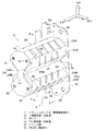
図1には、上記クラッシュボックス10の全体斜視図が示されている。また、図2〜図5には当該クラッシュボックス10の適宜断面図が示されている。
FIG. 1 is an overall perspective view of the
これらの図に示されるように、本実施形態のクラッシュボックス10は、上下二個の上側筒状部22及び下側筒状部24が軸直角方向(車両上下方向)に並列的に配置された筒状部の複合体として構成されている。図2及び図3に示されるように、上側筒状部22及び下側筒状部24は各々正八角形に形成されており、底壁と頂壁を共有することで全体としては高いエネルギー吸収性能を発揮する略8の字形状に形成されている。
As shown in these drawings, in the
また、上側筒状部22の左右の上部壁22A及び側部壁22C並びに下側筒状部24の左右の下部壁24A及び側部壁24Cには、圧縮座屈起点を特定するためのビード(脆弱部)26が所定の間隔で形成されている。なお、上部壁22Aに形成されたビード26と側部壁22Cに形成されたビード26とは互い違いに配置されている。同様に、下部壁24Cに形成されたビード26と側部壁24Cに形成されたビード26とは互い違いに配置されている。
Further, the left and right
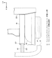
上記クラッシュボックス10の軸方向の一端部(前端部)は閉止されており、フロントバンパリインフォースメント12へ結合される底部28とされている。なお、底部28の先端面(前端面)は、フロントバンパリインフォースメント12の湾曲形状に合わせて所定角度の傾斜面とされている(図5参照)。一方、クラッシュボックス10の軸方向の他端部(後端部)は開放されており、フロントサイドメンバ18の前端部へ結合される矩形平板状のフランジ部30が周囲に一体に形成されている。フランジ部30の四隅には、ボルト挿通孔32が形成されている。なお、フランジ部30の板厚は、フロントサイドメンバ18の前端部への結合剛性を確保するべく、上側筒状部22及び下側筒状部24の板厚よりも厚く設定されている。
One end portion (front end portion) of the
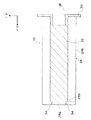
上述したクラッシュボックス10の底部28は、略8の字形状に形成された縦長の厚肉部28Aと、この厚肉部28Aの高さ方向中間部の左右両側を抉るように形成された一対の薄肉部28Bと、によって構成されている。
The
薄肉部28Bは、上側筒状部22の下部壁22Bと、下側筒状部24の上部壁24Bと、上側筒状部22及び下側筒状部24の中リブ(共有壁)23の三枚の壁が交差する部分を包囲した範囲に設定されている。一方、厚肉部28Aは、クラッシュボックス10の8の字状の外形形状から左右一対の薄肉部28Bを除いた範囲に設定されている。厚肉部28Aと薄肉部28Bとの間には段差34が形成されており、この段差34の高さは衝突初期のピーク荷重が発生するストロークに対応する所定高さ(数ミリ程度)に設定されている。
The thin-walled portion 28B includes three parts: a
さらに、厚肉部28Aの上下四箇所(上側筒状部22の中間両サイド二箇所と下側筒状部24の中間両サイド二箇所)には、フロントバンパリインフォースメント12への取付部である取付孔36が形成されている。取付孔36の内周面には雌ねじが形成されており、フロントバンパリインフォースメント12側から図示しないボルトが螺合されるようになっている。なお、クラッシュボックス10のフロントバンパリインフォースメント12側への締結方向及びフロントサイドメンバ18の前端部側への締結方向は、いずれも車両前後方向とされている。
Furthermore, the upper and lower four portions of the
ここで、図1及び図3〜図5に示されるように、上述したクラッシュボックス10の上側筒状部22と下側筒状部24とを隔成する中リブ23のフランジ部30の近傍(中リブ23の後端部)には、平面視で矩形状の脆弱部としての切欠部38が形成されている。この切欠部38が形成されたことにより、本体部である上側筒状部22及び下側筒状部24のフランジ部30の近傍部位が脆弱化されている。
Here, as shown in FIG. 1 and FIGS. 3 to 5, in the vicinity of the
さらに、上記構成のクラッシュボックス10は一部品によって構成されており、アルミニウム合金を鍛造成形することにより製作されている。概略的には、クラッシュボックス10は、前方押出し工法と後方押出し工法の二工程を活用した(組み合わせた)アルミニウム合金の鍛造によって製造されている。
Further, the
(作用・効果)
次に、本実施形態の作用並びに効果について説明する。
(Action / Effect)
Next, the operation and effect of this embodiment will be described.
本実施形態に係るクラッシュボックス10は、フロントバンパリインフォースメント12とフロントサイドメンバ18の前端部との間に組付けられる。そして、この車両が正面衝突すると、その際の衝突荷重はフロントバンパリインフォースメント12に入力される。入力された衝突荷重は、クラッシュボックス10を介してフロントサイドメンバ18へ伝達される。この際、クラッシュボックス10の上側筒状部22及び下側筒状部24が軸方向に圧縮されて各ビード26を起点として蛇腹状に順次変形(圧壊)することにより、所定のエネルギー吸収がなされる。
The
ここで、本実施形態に係るクラッシュボックス10では、上側筒状部22及び下側筒状部24の後端部に矩形平板状のフランジ部30を一体形成し、かかるフランジ部30を荷重伝達部であるフロントサイドメンバ20の前端部に取り付けたので、上側筒状部22及び下側筒状部24において軸圧縮後半に変形するフランジ部30に近い部分ほど断面拘束力が強くなる。従って、上側筒状部22及び下側筒状部24におけるフランジ部30の近傍の部位が潰れ難くなるが、本実施形態に係るクラッシュボックス10では、上側筒状部22及び下側筒状部24における断面拘束力が強くなる中リブ23の後端部に切欠部38を設けたので、軸圧縮後半での耐力を適度に低下させ、潰れ残りを低減する(潰れ率を向上させる)ことができる。その結果、本実施形態によれば、軸圧縮後半でのエネルギー吸収量が増加し、F‐S特性を理想的な特性である矩形状の特性に近づけることができる。
Here, in the
また、本実施形態では、クラッシュボックス10を鍛造成形によって形成したので、材料投入量を減らしたり、プレス能力を意図的に低下させる等することにより、切欠部38を成形の過程で同時に作ることができる。つまり、切欠部38を設定する後加工が不要となるため、生産性が向上される。さらに、材料投入量を減らしたり、プレス能力を下げることができるという利点は、クラッシュボックス10を鍛造成形で製作し易くなるという生産上の利点をもたらすことにもなる。その結果、本実施形態によれば、生産性の向上及び歩留まりの向上を図ることができる。
In the present embodiment, since the
〔実施形態の補足説明〕
なお、上述した本実施形態では、車両の衝撃吸収部材としてクラッシュボックス10を例にして説明したが、これに限らず、衝突時に軸圧縮荷重を受けて荷重入力側の端部から順次圧縮塑性変形していき、軸圧縮後半での断面拘束力が強くなる車体骨格部材(軸圧縮部材)であればすべて適用可能である。例えば、クラッシュボックスを設定せずに、フロントサイドメンバの前端部を直接軸圧縮塑性変形させる場合に本発明を適用してもよい。
[Supplementary explanation of the embodiment]
In the above-described embodiment, the
また、上述した本実施形態では、脆弱部として切欠部38を設定したが、これに限らず、軸圧縮後半での荷重増加を抑制することができる構成であればよく、例えば、薄肉部を設定する構成を採ってもよい。
Moreover, in this embodiment mentioned above, although the
さらに、上述した本実施形態では、中リブ23の後端部に切欠部38を設定したが、断面拘束力を増大させる要素にはアーク溶接やスポット溶接等による溶接部もあるので、かかる溶接部が軸圧縮後半に相当する位置に設定されている場合には、溶接部近傍に切欠部38等の脆弱部を設定すると同様の効果が得られる。
Further, in the above-described embodiment, the
また、上述した本実施形態では、アルミニウム合金の鍛造成形によってクラッシュボックス10を製作したが、これに限らず、押し出し成形によってクラッシュボックスを製作してもよい。この場合、切欠部(脆弱部)の設定は、後工程として切削加工によりなされる。
Moreover, in this embodiment mentioned above, although the
さらに、上述した本実施形態では、クラッシュボックス10の材質をアルミニウム合金材としたが、これに限らず、鉄、カーボン、樹脂、グラスファイバ等、種々の材料を適用することが可能である。
Further, in the present embodiment described above, the
また、上述した本実施形態では、クラッシュボックス10の本体部を軸圧壊性能が優れる上側筒状部22及び下側筒状部24から成る略8の字状に形成したが、これに限らず、「日」の字状等に形成してもよい。また、筒状部も二本に限らず、三本以上でもよい。
Moreover, in this embodiment mentioned above, although the main-body part of the
10 クラッシュボックス(衝撃吸収部材)
12 フロントバンパリインフォースメント(荷重入力部)
18 フロントサイドメンバ(荷重伝達部)
22 上側筒状部(本体部)
23 中リブ
24 下側筒状部(本体部)
30 フランジ部
38 切欠部(脆弱部)
10 Crash box (shock absorbing member)
12 Front bumper reinforcement (load input section)
18 Front side member (load transmission part)
22 Upper cylindrical part (main part)
23
30
Claims (2)
前記衝撃吸収部材は、衝突荷重の入力時に軸方向に圧縮変形する本体部と、当該本体部に一体的に設けられると共に荷重伝達部への取付用に供されるフランジ部と、を含む車体骨格部材として構成されており、
前記本体部において軸圧縮後半に変形する断面拘束力の強いフランジ部近傍の断面を部分的に脆弱化した、
ことを特徴とする車両の衝撃吸収部材。 An impact absorbing member for a vehicle that absorbs energy at the time of collision by being compressed and deformed in an axial direction interposed between a load input portion to which a collision load is input and a load transmission portion to which the collision load is transmitted,
The shock absorbing member includes a body portion that compresses and deforms in the axial direction when a collision load is input, and a flange portion that is provided integrally with the body portion and is used for attachment to the load transmission portion. Configured as a member,
In the main body part, the cross section in the vicinity of the flange part having a strong cross-sectional binding force that deforms in the latter half of the axial compression is partially weakened.
A shock absorbing member for a vehicle characterized by the above.
ことを特徴とする請求項1記載の車両の衝撃吸収部材。 The body portion of the impact absorbing member is formed by forging,
The impact absorbing member for a vehicle according to claim 1.
Priority Applications (1)
| Application Number | Priority Date | Filing Date | Title |
|---|---|---|---|
| JP2005173716A JP2006347265A (en) | 2005-06-14 | 2005-06-14 | Vehicular impact absorbing member |
Applications Claiming Priority (1)
| Application Number | Priority Date | Filing Date | Title |
|---|---|---|---|
| JP2005173716A JP2006347265A (en) | 2005-06-14 | 2005-06-14 | Vehicular impact absorbing member |
Publications (1)
| Publication Number | Publication Date |
|---|---|
| JP2006347265A true JP2006347265A (en) | 2006-12-28 |
Family
ID=37643568
Family Applications (1)
| Application Number | Title | Priority Date | Filing Date |
|---|---|---|---|
| JP2005173716A Pending JP2006347265A (en) | 2005-06-14 | 2005-06-14 | Vehicular impact absorbing member |
Country Status (1)
| Country | Link |
|---|---|
| JP (1) | JP2006347265A (en) |
Cited By (18)
| Publication number | Priority date | Publication date | Assignee | Title |
|---|---|---|---|---|
| JP2008296716A (en) * | 2007-05-30 | 2008-12-11 | Kobe Steel Ltd | Energy absorbing member |
| JP2009096225A (en) * | 2007-10-12 | 2009-05-07 | Kobe Steel Ltd | Energy absorbing member |
| JP2009154587A (en) * | 2007-12-25 | 2009-07-16 | Toyota Motor Corp | Shock absorbing structure |
| JP2009168115A (en) * | 2008-01-15 | 2009-07-30 | Toyota Motor Corp | Impact absorbing member |
| JP2010018047A (en) * | 2008-07-08 | 2010-01-28 | Kobe Steel Ltd | Bumper system of vehicle |
| WO2010038598A1 (en) * | 2008-10-02 | 2010-04-08 | 本田技研工業株式会社 | Structure for vehicle body front portion |
| JP2010083448A (en) * | 2008-10-02 | 2010-04-15 | Honda Motor Co Ltd | Vehicle front body structure |
| JP2011126412A (en) * | 2009-12-17 | 2011-06-30 | Aisin Keikinzoku Co Ltd | Impact absorption member for vehicle |
| US7980607B2 (en) | 2008-07-23 | 2011-07-19 | Toyotomi Kiko Co., Ltd. | Impact absorbing member |
| JP2014004973A (en) * | 2012-06-27 | 2014-01-16 | Kojima Press Industry Co Ltd | Crash box for vehicle and bumper device for vehicle and impact absorption structure for vehicle |
| JP2014088145A (en) * | 2012-10-31 | 2014-05-15 | Toyota Industries Corp | Attachment structure of assist grip |
| JP2016200233A (en) * | 2015-04-13 | 2016-12-01 | トヨタ車体株式会社 | Shock absorption member |
| CN106184087A (en) * | 2016-07-29 | 2016-12-07 | 奇瑞汽车股份有限公司 | A kind of automobile front protecting crossbeam assembly |
| EP3173293A1 (en) * | 2015-11-27 | 2017-05-31 | Ford Global Technologies, LLC | A structural member |
| GB2547196A (en) * | 2016-02-09 | 2017-08-16 | Gordon Murray Design Ltd | Impact energy absorbing structure |
| WO2017163502A1 (en) * | 2016-03-25 | 2017-09-28 | アイシン精機株式会社 | Crash box and manufacturing method therefor |
| JP2018089774A (en) * | 2016-11-30 | 2018-06-14 | トヨタ車体株式会社 | Vehicle member |
| CN108593311A (en) * | 2018-06-19 | 2018-09-28 | 中国汽车技术研究中心有限公司 | A kind of children's seat trolley side collision experimental rig and test method |
Citations (4)
| Publication number | Priority date | Publication date | Assignee | Title |
|---|---|---|---|---|
| JP2002188673A (en) * | 2000-12-25 | 2002-07-05 | Aisin Seiki Co Ltd | Joint structure of impact transmission member and impact absorption member and bumper |
| JP2003312401A (en) * | 2002-04-19 | 2003-11-06 | Aisin Seiki Co Ltd | Bumper device |
| JP2003312400A (en) * | 2002-04-19 | 2003-11-06 | Aisin Seiki Co Ltd | Bumper device |
| JP2005001462A (en) * | 2003-06-10 | 2005-01-06 | Toyota Motor Corp | Shock absorbing member for vehicle |
-
2005
- 2005-06-14 JP JP2005173716A patent/JP2006347265A/en active Pending
Patent Citations (4)
| Publication number | Priority date | Publication date | Assignee | Title |
|---|---|---|---|---|
| JP2002188673A (en) * | 2000-12-25 | 2002-07-05 | Aisin Seiki Co Ltd | Joint structure of impact transmission member and impact absorption member and bumper |
| JP2003312401A (en) * | 2002-04-19 | 2003-11-06 | Aisin Seiki Co Ltd | Bumper device |
| JP2003312400A (en) * | 2002-04-19 | 2003-11-06 | Aisin Seiki Co Ltd | Bumper device |
| JP2005001462A (en) * | 2003-06-10 | 2005-01-06 | Toyota Motor Corp | Shock absorbing member for vehicle |
Cited By (25)
| Publication number | Priority date | Publication date | Assignee | Title |
|---|---|---|---|---|
| JP2008296716A (en) * | 2007-05-30 | 2008-12-11 | Kobe Steel Ltd | Energy absorbing member |
| JP2009096225A (en) * | 2007-10-12 | 2009-05-07 | Kobe Steel Ltd | Energy absorbing member |
| JP2009154587A (en) * | 2007-12-25 | 2009-07-16 | Toyota Motor Corp | Shock absorbing structure |
| JP2009168115A (en) * | 2008-01-15 | 2009-07-30 | Toyota Motor Corp | Impact absorbing member |
| JP2010018047A (en) * | 2008-07-08 | 2010-01-28 | Kobe Steel Ltd | Bumper system of vehicle |
| US7980607B2 (en) | 2008-07-23 | 2011-07-19 | Toyotomi Kiko Co., Ltd. | Impact absorbing member |
| WO2010038598A1 (en) * | 2008-10-02 | 2010-04-08 | 本田技研工業株式会社 | Structure for vehicle body front portion |
| JP2010083448A (en) * | 2008-10-02 | 2010-04-15 | Honda Motor Co Ltd | Vehicle front body structure |
| US8256831B2 (en) | 2008-10-02 | 2012-09-04 | Honda Motor Co., Ltd. | Structure for vehicle body front portion |
| CN102137787B (en) * | 2008-10-02 | 2013-06-12 | 本田技研工业株式会社 | Structure for vehicle body front portion |
| JP2011126412A (en) * | 2009-12-17 | 2011-06-30 | Aisin Keikinzoku Co Ltd | Impact absorption member for vehicle |
| JP2014004973A (en) * | 2012-06-27 | 2014-01-16 | Kojima Press Industry Co Ltd | Crash box for vehicle and bumper device for vehicle and impact absorption structure for vehicle |
| JP2014088145A (en) * | 2012-10-31 | 2014-05-15 | Toyota Industries Corp | Attachment structure of assist grip |
| US8931818B2 (en) | 2012-10-31 | 2015-01-13 | Kabushiki Kaisha Toyota Jidoshokki | Mounting structure of assist grip |
| JP2016200233A (en) * | 2015-04-13 | 2016-12-01 | トヨタ車体株式会社 | Shock absorption member |
| EP3173293A1 (en) * | 2015-11-27 | 2017-05-31 | Ford Global Technologies, LLC | A structural member |
| US9834160B2 (en) | 2015-11-27 | 2017-12-05 | Ford Global Technologies, Llc | Structural member |
| GB2547196A (en) * | 2016-02-09 | 2017-08-16 | Gordon Murray Design Ltd | Impact energy absorbing structure |
| WO2017163502A1 (en) * | 2016-03-25 | 2017-09-28 | アイシン精機株式会社 | Crash box and manufacturing method therefor |
| US10661741B2 (en) | 2016-03-25 | 2020-05-26 | Aisin Seiki Kabushiki Kaisha | Crash box and manufacturing method of the same |
| CN106184087A (en) * | 2016-07-29 | 2016-12-07 | 奇瑞汽车股份有限公司 | A kind of automobile front protecting crossbeam assembly |
| CN106184087B (en) * | 2016-07-29 | 2018-10-26 | 奇瑞汽车股份有限公司 | A kind of automobile front protecting crossbeam assembly |
| JP2018089774A (en) * | 2016-11-30 | 2018-06-14 | トヨタ車体株式会社 | Vehicle member |
| US11052849B2 (en) | 2016-11-30 | 2021-07-06 | Toyota Shatai Kabushiki Kaisha | Vehicle member |
| CN108593311A (en) * | 2018-06-19 | 2018-09-28 | 中国汽车技术研究中心有限公司 | A kind of children's seat trolley side collision experimental rig and test method |
Similar Documents
| Publication | Publication Date | Title |
|---|---|---|
| JP2006347265A (en) | Vehicular impact absorbing member | |
| JP5078597B2 (en) | Shock absorption structure | |
| JP5587696B2 (en) | Vehicle shock absorber and vehicle bumper device | |
| JP4365232B2 (en) | Shock absorber for vehicle | |
| JP5862555B2 (en) | Auto body structure | |
| JP4973180B2 (en) | Method for manufacturing shock absorbing member | |
| WO2017111105A1 (en) | Energy absorbing member | |
| JP2006347262A (en) | Reinforcing structure of mounting portion to load transmitting portion of vehicular impact absorbing member | |
| CN111479725A (en) | Impact absorbing structure for vehicle | |
| WO2013183587A1 (en) | Vehicle frame member structure with excellent impact resistance performance | |
| WO2018088100A1 (en) | Impact absorption structure for vehicles | |
| JP2006290224A (en) | Vehicle body front part structure | |
| JP2006062561A (en) | Impact absorbing structure of vehicle | |
| JP6254448B2 (en) | Bumper beam for vehicles | |
| JP4045846B2 (en) | Impact energy absorbing member | |
| WO2018088101A1 (en) | Impact absorption structure for vehicles | |
| JP2008094309A (en) | Shock absorbing structure for vehicle frame | |
| WO2020085381A1 (en) | Automobile frame member and electric vehicle | |
| JP4285293B2 (en) | Shock absorption structure at the front of the vehicle | |
| JP7085517B2 (en) | Body front structure | |
| JP5038061B2 (en) | Bumper device for vehicle | |
| KR20070055014A (en) | Front impact absorption means of vehicle | |
| JP4759871B2 (en) | Impact energy absorbing member | |
| WO2014097765A1 (en) | Automobile body structure | |
| JP3241702B2 (en) | Energy absorbing structure for vehicles |
Legal Events
| Date | Code | Title | Description |
|---|---|---|---|
| A521 | Written amendment |
Effective date: 20080611 Free format text: JAPANESE INTERMEDIATE CODE: A821 |
|
| A621 | Written request for application examination |
Effective date: 20080611 Free format text: JAPANESE INTERMEDIATE CODE: A621 |
|
| A711 | Notification of change in applicant |
Free format text: JAPANESE INTERMEDIATE CODE: A711 Effective date: 20080611 |
|
| RD04 | Notification of resignation of power of attorney |
Effective date: 20080619 Free format text: JAPANESE INTERMEDIATE CODE: A7424 |
|
| A521 | Written amendment |
Effective date: 20080611 Free format text: JAPANESE INTERMEDIATE CODE: A821 |
|
| A521 | Written amendment |
Free format text: JAPANESE INTERMEDIATE CODE: A523 Effective date: 20080801 |
|
| A977 | Report on retrieval |
Free format text: JAPANESE INTERMEDIATE CODE: A971007 Effective date: 20100722 |
|
| A131 | Notification of reasons for refusal |
Free format text: JAPANESE INTERMEDIATE CODE: A131 Effective date: 20110203 |
|
| A521 | Written amendment |
Free format text: JAPANESE INTERMEDIATE CODE: A523 Effective date: 20110329 |
|
| A02 | Decision of refusal |
Effective date: 20110420 Free format text: JAPANESE INTERMEDIATE CODE: A02 |