JP2006331445A - Image processing apparatus and image processing method - Google Patents
Image processing apparatus and image processing method Download PDFInfo
- Publication number
- JP2006331445A JP2006331445A JP2006197923A JP2006197923A JP2006331445A JP 2006331445 A JP2006331445 A JP 2006331445A JP 2006197923 A JP2006197923 A JP 2006197923A JP 2006197923 A JP2006197923 A JP 2006197923A JP 2006331445 A JP2006331445 A JP 2006331445A
- Authority
- JP
- Japan
- Prior art keywords
- image
- pixel
- value
- pixel value
- conversion
- Prior art date
- Legal status (The legal status is an assumption and is not a legal conclusion. Google has not performed a legal analysis and makes no representation as to the accuracy of the status listed.)
- Granted
Links
- 238000012545 processing Methods 0.000 title claims abstract description 226
- 238000003672 processing method Methods 0.000 title abstract description 41
- 238000006243 chemical reaction Methods 0.000 claims abstract description 358
- 230000002093 peripheral effect Effects 0.000 claims description 79
- 238000004364 calculation method Methods 0.000 claims description 57
- 238000012937 correction Methods 0.000 claims description 50
- 238000000605 extraction Methods 0.000 claims description 44
- 230000008878 coupling Effects 0.000 claims description 35
- 238000010168 coupling process Methods 0.000 claims description 35
- 238000005859 coupling reaction Methods 0.000 claims description 35
- 238000009826 distribution Methods 0.000 claims description 24
- 238000009795 derivation Methods 0.000 claims description 17
- 230000002441 reversible effect Effects 0.000 claims description 12
- 239000000203 mixture Substances 0.000 claims description 11
- 238000003786 synthesis reaction Methods 0.000 claims description 11
- 230000015572 biosynthetic process Effects 0.000 claims description 10
- 239000002131 composite material Substances 0.000 claims description 8
- 230000003247 decreasing effect Effects 0.000 claims description 3
- 230000002194 synthesizing effect Effects 0.000 abstract description 20
- 238000000034 method Methods 0.000 description 144
- 239000013598 vector Substances 0.000 description 105
- 230000008569 process Effects 0.000 description 64
- 230000000007 visual effect Effects 0.000 description 64
- 238000010586 diagram Methods 0.000 description 46
- 238000011156 evaluation Methods 0.000 description 42
- 238000004422 calculation algorithm Methods 0.000 description 32
- 230000002068 genetic effect Effects 0.000 description 32
- 230000000694 effects Effects 0.000 description 31
- 230000006870 function Effects 0.000 description 31
- 239000003086 colorant Substances 0.000 description 21
- 230000006798 recombination Effects 0.000 description 18
- 238000005215 recombination Methods 0.000 description 17
- 230000035772 mutation Effects 0.000 description 11
- 210000000349 chromosome Anatomy 0.000 description 10
- 230000006872 improvement Effects 0.000 description 10
- 238000005457 optimization Methods 0.000 description 10
- 230000008901 benefit Effects 0.000 description 9
- 239000000284 extract Substances 0.000 description 8
- 230000004438 eyesight Effects 0.000 description 7
- 238000010187 selection method Methods 0.000 description 6
- 230000008859 change Effects 0.000 description 5
- 238000007796 conventional method Methods 0.000 description 5
- 238000005516 engineering process Methods 0.000 description 4
- 230000009466 transformation Effects 0.000 description 4
- 230000029777 axis specification Effects 0.000 description 3
- 238000003384 imaging method Methods 0.000 description 3
- 230000009467 reduction Effects 0.000 description 3
- 230000002829 reductive effect Effects 0.000 description 3
- 241000282412 Homo Species 0.000 description 2
- 238000009825 accumulation Methods 0.000 description 2
- 238000013459 approach Methods 0.000 description 2
- 210000001726 chromosome structure Anatomy 0.000 description 2
- 230000006835 compression Effects 0.000 description 2
- 238000007906 compression Methods 0.000 description 2
- 239000000470 constituent Substances 0.000 description 2
- 238000001914 filtration Methods 0.000 description 2
- 108090000623 proteins and genes Proteins 0.000 description 2
- 238000013139 quantization Methods 0.000 description 2
- 230000000717 retained effect Effects 0.000 description 2
- 208000019901 Anxiety disease Diseases 0.000 description 1
- 206010044565 Tremor Diseases 0.000 description 1
- 230000036506 anxiety Effects 0.000 description 1
- 238000013528 artificial neural network Methods 0.000 description 1
- 230000001174 ascending effect Effects 0.000 description 1
- 238000005282 brightening Methods 0.000 description 1
- 230000002759 chromosomal effect Effects 0.000 description 1
- 230000004456 color vision Effects 0.000 description 1
- 230000000295 complement effect Effects 0.000 description 1
- 230000001186 cumulative effect Effects 0.000 description 1
- 238000013461 design Methods 0.000 description 1
- 230000005484 gravity Effects 0.000 description 1
- 238000005286 illumination Methods 0.000 description 1
- 230000000670 limiting effect Effects 0.000 description 1
- 238000010801 machine learning Methods 0.000 description 1
- 238000004519 manufacturing process Methods 0.000 description 1
- 238000010606 normalization Methods 0.000 description 1
- 230000008447 perception Effects 0.000 description 1
- 230000005043 peripheral vision Effects 0.000 description 1
- 230000001737 promoting effect Effects 0.000 description 1
- 230000008707 rearrangement Effects 0.000 description 1
- 238000009738 saturating Methods 0.000 description 1
- 238000010186 staining Methods 0.000 description 1
- 230000001131 transforming effect Effects 0.000 description 1
- 238000013519 translation Methods 0.000 description 1
Images


Abstract
Description
本発明は、カメラ等で得られたカラー画像信号のコントラストや色を自動的に調整して、所望のコントラストや色調を持つ画像を得ることができる画像処理装置及び画像処理方法に関するものである。 The present invention relates to an image processing apparatus and an image processing method capable of automatically adjusting the contrast and color of a color image signal obtained by a camera or the like to obtain an image having a desired contrast and color tone.
ディジタルカメラで撮影されたカラー画像は、撮像素子であるCCD素子で得られたアナログ値におけるノイズ割合を表すSNレベルやアナログ値をディジタル値に変換する際の変換精度等の影響で、実際に撮影された自然画像の持つ画素濃度のダイナミックレンジよりも狭いレンジに制限されるため、影がかかった細部での情報が損失する現象が発生する傾向がある。特に画像内に明るい領域と暗い領域が混在するようなサンプルを撮影しようとした場合にその傾向は大きい。その改善として、ディジタル画像の輝度等の範囲をより輝度の高い画像部分からより輝度の低い画像部分までに拡げるように、コントラスト強調を行う手法がまず考えられる。そのコントラスト強調の従来手法としては、原画像を構成する全画素の輝度値の分布状態を示すヒストグラムを作成し、ヒストグラムの累積曲線を輝度変換曲線として原画像中の画素の輝度値を新な輝度値に変換し、画像のコントラストを強調するヒストグラム均等化手法がある。この手法は、原画像全領域の画素の輝度を同一の輝度変換曲線で新たな輝度に変換するために、部分的にはかえってコントラストが低下してしまう部分が生じることがある。このため、画像全体にわたってコントラスト強調を行いたい場合には、その領域に合ったコントラスト強調処理を行う必要がある。 A color image taken with a digital camera is actually taken due to the influence of the SN level representing the noise ratio in the analog value obtained by the CCD element, which is an image sensor, and the conversion accuracy when the analog value is converted into a digital value. Since the natural image is limited to a range narrower than the dynamic range of the pixel density, there is a tendency that information in a shadowed detail is lost. This tendency is particularly significant when trying to photograph a sample in which a bright area and a dark area are mixed in the image. As an improvement, first, a method of performing contrast enhancement so as to expand the range of the brightness of the digital image from an image portion with higher brightness to an image portion with lower brightness can be considered. As a conventional method of contrast enhancement, a histogram showing the distribution of the luminance values of all the pixels that make up the original image is created, and the luminance value of the pixels in the original image is set to a new luminance using the histogram's cumulative curve as the luminance conversion curve. There is a histogram equalization technique that converts to a value and enhances the contrast of the image. In this method, since the luminance of the pixels in the entire original image region is converted to a new luminance using the same luminance conversion curve, a portion where contrast is lowered may occur. For this reason, when it is desired to perform contrast enhancement over the entire image, it is necessary to perform contrast enhancement processing suitable for the region.
この手法のさらなる改善として、画像を複数の矩形領域に分割し、各々の領域毎に上記ヒストグラム均等化手法を適用する局所的ヒストグラム均等化手法も多く提案されており(例えば特開2000−285230号公報参照、文献1)、その構成図は図28のようになる。 As a further improvement of this technique, many local histogram equalization techniques that divide an image into a plurality of rectangular areas and apply the histogram equalization technique for each area have been proposed (for example, Japanese Patent Laid-Open No. 2000-285230). Refer to the publication, reference 1), and its configuration diagram is as shown in FIG.
図28は文献1における画像処理装置を示すブロック図である。 FIG. 28 is a block diagram showing an image processing apparatus in Literature-1.
図28はコントラスト強調部を表したものであり、画像を矩形に分割する画像データ分割手段281、矩形ごとにヒストグラムを作成するヒストグラム作成手段282、矩形ごとにコントラストの伸張を行うコントラスト伸張手段283よりなる。しかし、この手法を用いた場合、コントラストが強調されすぎる矩形領域が発生したり、隣接する矩形領域間の境界でコントラストが不連続になる可能性があるなどの問題点が指摘されている。
FIG. 28 shows a contrast emphasizing unit, which includes an image
一方、ヒストグラムを利用しないで、このような問題の解決策として、フィールドごとにディジタルカメラのシャッタ時間や絞りを変えて、明るい部分と暗い部分を別々に撮像し、得られた各々の情報を1枚の画像に合成して中間調濃度を実現することで、実際に撮影された自然画像の持つ画素濃度のダイナミックレンジに近づける手法も提案されている。その例として、特開平6−141229号公報(文献2)に参照されている例があり、その装置の構成図は図29のようになる。 On the other hand, as a solution to such a problem without using the histogram, the bright time and the dark portion are separately imaged by changing the shutter time and aperture of the digital camera for each field, and each information obtained is 1 A method has also been proposed in which a halftone density is realized by synthesizing with a single image so as to approach the dynamic range of the pixel density of an actually captured natural image. As an example, there is an example referred to in Japanese Patent Application Laid-Open No. 6-141229 (Document 2), and the configuration diagram of the apparatus is as shown in FIG.
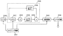
図29は文献2における撮像装置を示すブロック図である。
FIG. 29 is a block diagram showing an imaging apparatus in
図29において、290は被写体の光電効果を行う撮像素子(CCD)、291は画像信号を記録するメモリ、292は信号レベルを常数倍する乗算手段、293,298は画像信号のレベルに応じて重みを付加するレベル重み手段、294は信号を加算する加算手段、295は画像信号の速度を変換する速度変換手段、296は画像信号のレベルを圧縮するレベル圧縮手段、297は各ブロックのタイミングを制御するタイミング制御手段である。この装置は、撮像素子における電荷蓄積期間の異なる2枚以上の画像の信号レベルに応じて重み付け合成を行い、得られた合成画像出力を標準テレビ信号の速度に変換するとともに、テレビ信号での基準レベルに圧縮するテレビ撮像装置に関するものであるため、速度変換手段、レベル圧縮手段等を有する。そのため、ディジタルカメラに当てはめる場合、速度変換手段やレベル圧縮手段は必要な構成要素ではない。しかし、この装置のように複数の電荷蓄積期間で得られた画像合成による手法の場合、合成された画像におけるコントラストの不連続性は生じにくいが、最低2枚の画像を続けて取るため、原理的に同じ画像を取ることができない。そのため、これらの画像を合成した場合、シャッタ速度にも影響されるが合成画像の細部がぼけたりずれたりする画像が作成される可能性がある。また、明るい部分を撮影する際の濃度レンジと暗い部分を撮影する際の濃度レンジで画像内の持つ濃度レンジ全域をカバーできていない場合、その2つの中間濃度レンジで不連続性が生じる危険もある。
In FIG. 29,
ところで、このような影のかかった領域での細部及び色を人間が観察した場合、人間の視覚は上記のような問題を発生させることなく、画像の持つ広い濃度のダイナミクスや色を知覚することができる。このような人間の視覚を中心とした中央視野/周辺視野レティネックスの概念は、Edwin Land(エドウィン・ランド)により(「An Alternativ Technique for the Computation of the Designator in the Retinex Theory of Color Vision」National Academy of Science、第84巻、pp.3078からpp.3080(1986))の中で紹介されている。この中では、人間の視覚のレティネックスの概念では、中央視野が2から4基礎単位分の直径を持ち、周辺視野が中央視野の約200から250倍の直径を有する逆2乗関数で記述されている。そして、中央視野、周辺視野各々の視野内での信号強度の空間的平均が知覚される強度に関係するとして定義されている。これらの原理に従い、上記のような暗部における色と明度表現を改善する手法が近年提案されている。この例は国際公開番号W097/45809(日本では特表2000−511315号公表、文献3)で記述されている。 By the way, when humans observe details and colors in such shadowed areas, human vision can perceive wide-range dynamics and colors of images without causing the above problems. Can do. The concept of central vision / peripheral vision Retinex centered on human vision is described by Edwin Land ("An Alternative Technology for the Design of the Designer in the Retinax Theorem Theorem Theorem Theorem Theorem Theorem Theorem in the Rethenology Theorem." of Science, vol. 84, pp. 3078 to pp. 3080 (1986)). In this, the Retinex concept of human vision is described by an inverse square function with a central visual field having a diameter of 2 to 4 basic units and a peripheral visual field having a diameter approximately 200 to 250 times the central visual field. ing. Then, the spatial average of the signal intensity in each of the central visual field and the peripheral visual field is defined as related to the perceived intensity. In recent years, a technique for improving the color and lightness expression in the dark part as described above has been proposed in accordance with these principles. This example is described in International Publication No. W097 / 45809 (published in Japanese translation table 2000-511315, Document 3).
図30は文献3におけるディジタル画像改善方法の説明図である。なお、ここではグレースケール画像を例に説明するが、カラー画像に対しても拡張することができる。画像の(i,j)における画素値I(i,j)は、プロセッサ301及びフィルタ302によって調整され、フィルタリング処理が行われる。画素ごとに、プロセッサ301は、(数1)のような調整画素値I’(i,j)を算出する。
FIG. 30 is an explanatory diagram of the digital image improvement method in
![]()
![]()
ここで、F(i,j)は周辺視野を表す周辺視野関数であり、「*」は畳み込み演算処理を示す。そして、F(i,j)が(数2)の条件を満足するように正規化係数Kが決定されており、これにより(数1)の第2項は、周辺視野における画素値の平均値に相当する。 Here, F (i, j) is a peripheral visual field function representing the peripheral visual field, and “*” indicates a convolution calculation process. Then, the normalization coefficient K is determined so that F (i, j) satisfies the condition of (Equation 2), whereby the second term of (Equation 1) is the average value of the pixel values in the peripheral visual field. It corresponds to.
![]()
![]()
つまり、(数1)は大きな領域における画素値平均値に対する各画素の画素値の比率を対数変換したものに相当する。周辺視野関数F(i,j)は、人間の視覚モデルとの対応から対象画素に近づくほど寄与する割合が高いように設計されており、(数3)のようなガウス関数が適用される。 That is, (Equation 1) corresponds to a logarithmic conversion of the ratio of the pixel value of each pixel to the average pixel value in a large area. The peripheral visual field function F (i, j) is designed so that the contribution ratio increases as it approaches the target pixel from the correspondence with the human visual model, and a Gaussian function like (Equation 3) is applied.
ここでcは各画素値I(i,j)の調整画素値I’(i,j)をコントロールするための定数である。 Here, c is a constant for controlling the adjusted pixel value I ′ (i, j) of each pixel value I (i, j).
以上のように、文献3のディジタル画像改善方法では、周辺視野での平均画素値に対する対象画素値を調整された画素値I’(i,j)として算出し、この値に対して、ディスプレイ303によって使用されるレティネックス出力R(i,j)を生成するためのフィルタ処理が302により行われる。302はI’(i,j)を対数領域からディスプレイ303で扱われるR(i,j)の画素値領域へ変換するものであり、処理の簡便化のために全ての画素に対して同一のオフセット及び利得変換関数を適用する処理が用いられる。
As described above, in the digital image improvement method of
しかしながら、この手法の場合、周辺視野関数を制御するcによる影響を大きく受ける。例えば、このcが大きな値になると対象画素に寄与する周辺視野が大きくなることで、大きな影における色の補償のみが可能となるが、一方、このcが小さい値の場合、対象画素近傍のみが影響を与えることとなり、小さな影領域での改善のみが見受けられる。このように扱う画像内の画素値のダイナミックスレンジに応じて適切なcを考慮する必要があり画像依存性の問題が挙げられる。その改善として、複数の周辺視野領域を設ける手法も同じ特許内に提案されているが、いくつ周辺視野領域を用意するかが明確になっておらず、改善精度を向上されるために大きな周辺領域から小さい周辺領域を多く用意することにより、処理時間が膨大になってしまうという問題点がある。 However, this method is greatly affected by c that controls the peripheral visual field function. For example, if this c is a large value, the peripheral visual field contributing to the target pixel is increased, so that only color compensation in a large shadow is possible. On the other hand, if this c is a small value, only the vicinity of the target pixel is detected. Only an improvement in small shadow areas can be seen. Appropriate c must be taken into account according to the dynamic range of pixel values in the image to be handled in this way, and there is a problem of image dependency. As an improvement, a method for providing a plurality of peripheral visual field areas has been proposed in the same patent. Therefore, there is a problem that the processing time becomes enormous by preparing many small peripheral areas.
次に、フィルタ302では、ディスプレイ303で使用される実際の画素値に変換する処理が行われているが、この方法ではどの画像に対しても同一のオフセット及び利得変換関数処理をするように設定されており、この最適なオフセット及び利得変換関数の設定には経験的知見を要する点も問題として挙げられる。さらに、複数の定数cにより設定される最大の周辺視野内で画素値変動が非常に小さい場合、調整された画素値I’(i,j)は複数領域を用意してもI(i,j)に関係なく1.0近傍になる。このような場合、画素値変動の小さい対象画素でのI’(i,j)はその入力画像全体におけるI’(i,j)の平均近傍に位置する場合が多く、フィルタ302におけるオフセット及び利得変換関数如何に問わず、実際の画素値における中央付近に向かいやすい傾向がある。特にハイライト輝度をもつ一様に広い画像領域では、調整後の輝度が下がる方向に調整されやすく視覚的に悪化する問題がある。
Next, in the
一方、画像処理として色調整処理を用いた場合、従来の色調整処理では、予め色変換テーブル内に変換前の色と変換後の色を定義する手法が用いられたが、例えばディジタルカメラで取られた画像をよりきれいにしたいような欲求の場合、変換前の色は入力画像を見るまで判明しないことが多く、予め一律に決めることができず、自動的に色調整を行うことができないという問題点がある。この改善として、入力画像において色のヒストグラムをとり、その上位色を色変換テーブル内の変換後の色で変換する手法も考えられるが、単純に色のヒストグラムを取りだけでは変換後の色バランスが崩れる可能性が大きかった。
このように、従来のヒストグラムに基づくコントラスト強調処理技術は、特定の部分のコントラストが強調されすぎたり、局所的に隣接する矩形領域境界で不連続性を示すことがあるという問題点を有していた。また、複数の絞り条件等で撮像された複数画像を合成した場合、原理的には同じ被写体を撮像することができず、合成画像細部のぼけや色ずれを生じる可能性があるという問題点を有していた。さらに、従来の人間の視覚モデルをもとにしたコントラスト調整技術では、人間の周辺視野を規定するための定数や最終的に扱うための実際の画素値に変換する際のフィルタ処理の設計に経験的知識を多く含むという問題点を有していた。そのうえ、特にハイライト輝度をもつ一様に広い画像領域では、調整後の輝度が下がる方向に調整されやすく視覚的に悪化するという問題点を有していた。 As described above, the conventional contrast enhancement processing technique based on the histogram has a problem in that the contrast of a specific portion is excessively emphasized or discontinuity may be shown at a locally adjacent rectangular region boundary. It was. In addition, when a plurality of images captured under a plurality of aperture conditions are combined, in principle, the same subject cannot be captured, and there is a possibility that the composite image details may be blurred or color misalignment may occur. Had. Furthermore, with contrast adjustment technology based on the conventional human visual model, we have experience in designing filter processing when converting to constants for defining the peripheral visual field of humans and actual pixel values for final handling. Had the problem of including a lot of technical knowledge. In addition, particularly in a uniformly wide image area having highlight luminance, there is a problem that the luminance after adjustment is easily adjusted in a decreasing direction and visually deteriorates.
この画像処理装置および画像処理方法では、撮像された明暗部を持つ画像のみを用いて簡易に撮像画像のコントラストを調整することができ、入力画像に対する依存性と変換後の色バランスの崩れを無くすことができることが要求されている。 In this image processing apparatus and image processing method, it is possible to easily adjust the contrast of the captured image using only the captured image having a bright and dark part, and to eliminate the dependence on the input image and the collapse of the color balance after conversion. It is required to be able to.
本発明は、この要求を満たすため、撮像された明暗部を持つ画像のみを用いて簡易に撮像画像のコントラストを調整することができ、また入力画像に対する依存性と変換後の色バランスの崩れを無くすことができる画像処理装置、および、撮像された明暗部を持つ画像のみを用いて簡易に撮像画像のコントラストを調整し、また入力画像に対する依存性と変換後の色バランスの崩れを無くすための画像処理方法を提供することを目的とする。 In order to satisfy this requirement, the present invention can easily adjust the contrast of the captured image using only the captured image having a bright and dark part, and also eliminates dependency on the input image and collapse of the color balance after conversion. An image processing device that can be eliminated, and the contrast of the captured image can be easily adjusted using only the captured image having a bright and dark portion, and the dependency on the input image and the collapse of the color balance after conversion are eliminated. An object is to provide an image processing method.
画像データに対しコントラスト調整を行う画像処理装置において、処理対象画素の画素値と前記処理対象画素の周辺領域に含まれる複数の画素の画素値とを取得する手段と、前記処理対象画素の画素値と前記周辺領域に含まれる複数の画素の画素値又はその変換値との比較に基づいて前記処理対象画素の画素値を変更し出力するコントラスト調整手段と、出力された個々の画素値より画像データを生成する手段と、を備え、前記コントラスト調整手段は、前記周辺領域に含まれる複数の画素が一様に略同じ画素値を示す場合は、前記処理対象画素に対して前記コントラスト調整を行なわずに前記処理対象画素の画素値を出力すること、ことを特徴とする。 In an image processing apparatus that performs contrast adjustment on image data, means for obtaining a pixel value of a processing target pixel and pixel values of a plurality of pixels included in a peripheral region of the processing target pixel, and a pixel value of the processing target pixel And a contrast adjusting means for changing and outputting the pixel value of the pixel to be processed based on a comparison between the pixel values of the plurality of pixels included in the peripheral region or a converted value thereof, and image data from the output individual pixel values And the contrast adjusting means does not perform the contrast adjustment on the processing target pixel when a plurality of pixels included in the peripheral region uniformly show substantially the same pixel value. And outputting a pixel value of the pixel to be processed.
この構成により大きな領域で一律な入力画像のハイライト部(白)やブラック部を処理対象外として除去することで、前述のようにそのような領域でのコントラスト調整画像に発生しやすい輝度レベルの大きな変動を抑えることができる。 With this configuration, the highlight (white) and black portions of the input image that are uniform in a large area are removed from the processing target, so that the brightness level that is likely to occur in the contrast-adjusted image in such an area as described above. Large fluctuations can be suppressed.
なお、これ以降で、画素位置(i,j)の単位には全て画素単位が用いられることする。また、各実施例(実施の形態)におけるステップは、ハードウェアで構成してもソフトウェアで構成してもよい。 In the following, pixel units are all used as the unit of pixel position (i, j). Further, the steps in the respective examples (embodiments) may be configured by hardware or software.
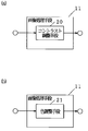
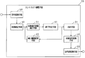
図1は本発明の実施例(実施の形態)1による画像処理装置の基本構成を示すブロック図である。また、図2(a)は図1の画像処理手段を示すブロック図、図3は図2(a)のコントラスト調整手段を示すブロック図、図10は図1の画像合成手段を示すブロック図、図11は人間の視覚を模式的に示す説明図である。 FIG. 1 is a block diagram showing a basic configuration of an image processing apparatus according to an embodiment (embodiment) 1 of the present invention. 2A is a block diagram showing the image processing means in FIG. 1, FIG. 3 is a block diagram showing the contrast adjusting means in FIG. 2A, and FIG. 10 is a block diagram showing the image synthesizing means in FIG. FIG. 11 is an explanatory diagram schematically showing human vision.
図1において、viはアナログ入力画像であり、voは最終的に出力される出力画像、vは後述の画像処理手段11で得られた処理後の画像である。10はCCD素子等の撮像素子からのアナログ画像信号viをディジタル画像データに変換する画像入力手段、11は画像入力手段10で得られたディジタル画像データに所望の画像処理を行う画像処理手段、12は画像入力手段からのディジタル画像データと画像処理手段11で得られた処理済みディジタル画像データvとを合成する画像合成手段、13は画像合成手段12で得られた合成ディジタル画像データを最終処理後の画像(アナログ画像信号)として所望のデバイス(プリンタ、ディスプレイ等)へ出力するための画像出力手段である。なお、本実施例(実施の形態)では、画像処理手段11における画像処理は、図2(a)で示すように、入力画像のコントラスト調整処理を行うコントラスト調整手段20で表されるものとする。その際、コントラスト調整手段は図3のような構成になる、図3において、30は対象画素Pij(i,j)におけるカラー3成分値VPij(r(i,j),g(i,j),b(i,j))からPijの広さcの周囲画素との比較によりコントラスト調整量VRPij(Rr(i,j),Rg(i,j),Rb(i,j))を算出する補正情報導出手段、31は補正情報導出手段30で得られたコントラスト調整量VRPijから、有効となる範囲を限定し抽出する抽出手段、32は抽出手段31で選択されたコントラスト調整量VRPijを実際の画素Pijにおける調整後の画素値VPdij(rd(i,j),gd(i,j),bd(i,j))に変換する画素値変換手段である。また、画像合成手段12は、図10に示されるように、入力画像1内の輝度をもとに入力画像viとコントラスト調整手段20で得られた調整後の画像vとのどちらを優先するかを決める選択基準値判定手段100と、選択基準値判定手段100の結果をもとに、入力画像viとコントラスト調整手段20で得られた調整後の画像vとに掛かる結合係数ws(S=1,3;ここで1は入力画像viに掛かる結合係数であり、3は調整後の画像vに掛かる結合係数を示す)を決定する結合係数導出手段101と、結合係数導出手段101で得られた結合係数w0、w1を使って、入力画像viとコントラスト調整手段で得られた調整後の画像vとの加重平均画像を生成する加重平均合成手段102より構成される。
In FIG. 1, vi is an analog input image, vo is an output image that is finally output, and v is a processed image obtained by an
以上のように構成された画像処理装置の動作についてその動作を説明する。 The operation of the image processing apparatus configured as described above will be described.
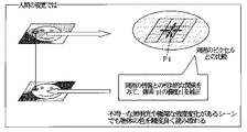
画像入力手段10を介して、画像処理手段11に、カラー画像viがディジタル入力される。画像入力手段10では、カラー画像の場合、通常レッドr、グリーンg、ブルーbの成分データが画像入力手段10の精度で(8ビットならば0から255の値で)得られる。画像入力手段10では、この値を0.0から1.0の値に正規化する。次に、ディジタル入力画像に対して、入力画像の暗部におけるコントラストを改善するためのコントラスト調整処理がコントラスト調整手段20で行われる。コントラスト調整手段20では後述の図12のように行われる。人間の視覚では、図11に模式的に示されるように、対象画素Pijに対して知覚された画素値のみでPijの画素情報(色、コントラストなど)を認知するのではなく、対象画素Pijの画素値をその周囲にある画素の情報との相対的な関係により調整することで、Pijの画素情報を知覚している。これは、従来の技術で説明したように、Edwin Landにより紹介されたレティネックス概念と呼ばれるものであり、このような知覚により一部だけ別の照明を受けているような不均一な照明光や極端に画素値の強度変化があるようなシーンでも、物体の色を精度よく認知することができる。本実施例(実施の形態)でも、この概念を利用することで影のような暗部における色や細部情報を明確にする。
The color image vi is digitally input to the
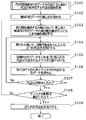
図12は、本実施例(実施の形態)による画像処理装置のコントラスト調整手段20における動作を示すフローチャートである。 FIG. 12 is a flowchart showing the operation of the contrast adjusting means 20 of the image processing apparatus according to the present embodiment (embodiment).
図12において、まず、補正情報導出手段30は、入力画像内における画素Pijの各成分の最大値Vmax(rx,gx,bx)と最小値Vmin(rn,gn,bn)を算出する(S1)。これは、出力画像voにおける最小画素値と最大画素値が入力画像viと大きく異なった場合、両者の画像の違和感が大きくなることをできるだけ抑えるために、出力画像voの画素値の最小画素値と最大画素値を入力画像viの最小画素値と最大画素値に合わせるための処理である。次に、対象画素Pijの画素値VPijをLandにおける中心視野と見なし、その周囲にc画素の矩形領域に属する領域を周辺視野と見なす。そして、補正情報導出手段30は、周辺視野における画素値の加重平均画素値VAPij(Ar(i,j),Ag(i,j),Ab(i,j))を求めるとともに(S2)、このVAPijとVPijの間の相対的関係につながるコントラスト調整量VRPij(Rr(i,j),Rg(i,j),Rb(i,j))を算出する(S3)。このVAPijとして、従来の技術のように(数1)の2項におけるc画素の周辺視野内における画素値VPij(r(i,j),g(i,j),b(i,j))と(数2)、(数3)のようにガウス関数で定義された周辺視野関数F(x,y)の畳み込み積分値で定義することも可能であり、加重平均画素値VAPijも(数1)を画素値を構成する3成分独立に定義することも可能である。しかし、本実施例(実施の形態)では、処理の簡単化と高速化を考慮して、(数4)のようにVAPijはc画素の周辺視野内における画素値VPij(r(i,j),g(i,j),b(i,j))の平均値を定義した。そして、コントラスト調整量VRPij(Rr(i,j),Rg(i,j),Rb(i,j))も(数1)のように対数変換値の差分を用いるのではなく(数5)のように各成分ごとの画素値VPijの加重平均画素値VAPijに対する比を定義することとした。
In FIG. 12, first, the correction
補正情報導出手段30は、以上のような対象画素Pijに対するコントラスト調整量VRPijを入力画像内の全ての画像に対して行う(S4)。その後、抽出手段31は、コントラスト調整量VRPijの成分ごとの平均値VaR(aRr,aRg,aRb)と標準偏差量VdR(dRr,dRg,dRb)を求め(S5)、その値を使ってコントラスト調整量VRPijより抽出される際の最小値eminと最大値emaxを導出する(S6)。この導出としても多くの方法があるが、ここでは、emaxの候補としてaRr+α×dRr、aRg+α×dRg、aRb+α×dRbを求め、この3値の内の最大値をemaxとする。そして、eminの候補としてaRr−β×dRr、aRg−β×dRg、aRb−β×dRbを求め、この3値の内の最小値をeminとする。こうすることで、抽出されたコントラスト調整量VRPijの各成分のバランスが崩れないように、必要とする領域を抽出することとした。次に、画素値変換手段32は、このemaxとeminを使って、コントラスト調整量VRPij(Rr(i,j),Rg(i,j),Rb(i,j))の各成分は0.0から1.0の範囲内の値に変換され(S7)、変換値を入力画像のVmax(rx,gx,bx)と最小値Vmin(rn,gn,bn)内に抑える処理を行う(S8)。こうして得られたコントラスト調整量VRPijを対象画素Pijにおけるコントラスト調整の画素値と見なされ、コントラスト調整処理が終了する(S9)。終了か否かの判定は画素値変換手段32が行う。
The correction
このような一連の処理により、周辺視野内での加重平均画素値に対する対象画素値の比の分布で中心付近部分のみは取り出され、中心からの変動量は強調されるとともに、中心付近から大きく外れた比の値を持つ画素のコントラスト調整量VRPijは1.0もしくは0.0になりやすくなる。そのため、中心視野である対象画素Pijとその周辺視野における画素との差が少しでもある領域はその差が強調されやすくなりコントラスト強調が行われ、影内の細部や入力機器のレンジ不足で埋もれてしまった色情報を強調して表現することができるようになる。本実施例(実施の形態)の場合、各画素におけるコントラスト調整量の導出が従来のレティネックス概念による手法よりも簡易な形で構成されている。そして、従来のレティネックス概念による手法では、各画素におけるコントラスト調整量から実際の画素値成分へ変換する際のフィルタ処理(オフセット、利得変換関数)の設定が経験的知識を要することが問題とされていたが、本実施例(実施の形態)ではその必要がないことが利点として挙げられる。一方、周辺視野内での加重平均画素値に対する対象画素値の比の分布で中心付近部分のみを抽出し、その前後の領域を0.0もしくは1.0で飽和させることにより、このコントラスト調整処理で得られた処理後の画像voは全体的に輝度レベルが中心付近に集まる問題が生じる可能性がある。この問題及び、従来の技術で説明した非常に大きな領域で一律な色を持つハイライト部での輝度レベルの低下を改善するために、本実施例(実施の形態)では、入力画像viとこの処理後の画像voを適応的に合成することで、入力画像viが本来持つ輝度レベルの低減や上昇を抑えることとしたのである。 By such a series of processing, only the portion near the center is extracted in the distribution of the ratio of the target pixel value to the weighted average pixel value in the peripheral visual field, the amount of variation from the center is emphasized, and the deviation from the center is greatly deviated. The contrast adjustment amount VRPij of the pixel having the ratio value is likely to be 1.0 or 0.0. For this reason, the region where the difference between the target pixel Pij as the central visual field and the pixels in the peripheral visual field is slightly enhanced, the difference is easily enhanced, and contrast enhancement is performed, and the details in the shadow and the range of the input device are insufficient. It becomes possible to emphasize and express the color information. In the case of the present embodiment (embodiment), the derivation of the contrast adjustment amount in each pixel is configured in a simpler form than the conventional method based on the Retinex concept. In the conventional method based on the Retinex concept, the setting of the filter processing (offset, gain conversion function) when converting the contrast adjustment amount in each pixel into the actual pixel value component requires an empirical knowledge. However, in the present embodiment (embodiment), it is mentioned as an advantage that it is not necessary. On the other hand, this contrast adjustment process is performed by extracting only the vicinity of the center in the distribution of the ratio of the target pixel value to the weighted average pixel value in the peripheral visual field, and saturating the area before and after that at 0.0 or 1.0. There is a possibility that the image vo after processing obtained in (1) may have a problem that the luminance level collects near the center as a whole. In this embodiment (embodiment), in order to improve this problem and the reduction of the luminance level in the highlight portion having a uniform color in a very large area described in the prior art, the input image vi and this By adaptively synthesizing the processed image vo, the reduction or increase in the luminance level inherent in the input image vi is suppressed.
画像合成手段12における画像合成処理では、このコントラスト調整処理での処理後画像vと入力画像viを受けて図13で示されているように処理が実行される。
In the image synthesizing process in the
図13は本発明の実施例(実施の形態)1による画像処理装置の画像合成手段12の動作を示すフローチャートである。
FIG. 13 is a flowchart showing the operation of the image synthesizing means 12 of the image processing apparatus according to
ここでは、まず、選択基準値判定手段100は、入力画像における各画素Pijの輝度y(i,j)を計算する(S11)。そして、予め用意されたしきい値Th_hとTh_lを各画素輝度y(i,j)と比較する(S12)。その際、Th_l>y(i,j)またはy(i,j)>Th_hの場合は、選択基準値判定手段100は、さらにPijのcの矩形の周辺視野領域における平均輝度Ay(i,j)を求める(S13)。そして、y(i,j)が|Ay(i,j)−y(i,j)|<Th_len(S14)を満足する場合には、対象画素Pijにおける入力画像viにおける画素値VPij(r(i,j),g(i,j),b(i,j))を処理済画像voの画素Pijの値であるVWPij(WRr(i,j),WRg(i,j),WRb(i,j))に置き換える処理を行う(S15)。この処理は、従来の技術で説明したように、周辺視野領域cより大きな領域で変動が非常に小さい場合でのPijにおけるコントラスト調整量は1.0近傍に集中しやすいことを考慮した処理であり、この処理により大きな領域で一律な入力画像のハイライト部(白)やブラック部を処理対象外として除去することで、前述のようにそのような領域でのコントラスト調整画像に発生しやすい輝度レベルの大きな変動を抑えることを目的とする。
Here, first, the selection reference
次に上記条件に属さないような場合は、結合係数導出手段101は、入力画像viのPijにおける輝度値y(i,j)と処理済画像vの対応する画素での輝度値yd(i,j)を比較し(S16)、その両者間の誤差の絶対値len=|y(i,j)−yd(i,j)|を用意されたw3決定関数に入力することで、処理済画像vの占める結合係数w3を決定する(S17)。そして入力画像viの占める結合係数w1はw1=1.0−w3より決定する。このw3決定関数も一律に決まらないが、ここでは簡易目的のため、(数6)のようなしきい値関数g(X)を使用する。
Next, in the case where the above condition is not satisfied, the coupling
そして、加重平均合成手段102は、このw1とw3を使って、Pijにおける入力画像viの画素値VPijと処理済画像vの画素値VRPijの加重平均画素値VWPij(WRr(i,j),WRg(i,j),WRb(i,j))を求め(S17)、画像vの対応する画素位置に埋め込む(S18)。このような一連の判定、加重平均処理を全画素に対して行うことで(S19)、最終的に画像出力手段13で出力される出力画像voを生成するのである。 The weighted average combining means 102 uses the w1 and w3 to calculate the weighted average pixel value VWPij (WRr (i, j), WRg) of the pixel value VPij of the input image vi and the pixel value VRPij of the processed image v using Pij. (I, j), WRb (i, j)) is obtained (S17) and embedded in the corresponding pixel position of the image v (S18). By performing such a series of determination and weighted average processing for all the pixels (S19), an output image vo that is finally output by the image output means 13 is generated.
以上のような構成や処理を行うことで本実施例(実施の形態)による画像処理装置は、従来の技術の問題点を解決するとともにその利点を生かすことで、簡易かつ高精度に入力画像のコントラスト調整を行うことができる。 By performing the configuration and processing as described above, the image processing apparatus according to the present embodiment (embodiment) solves the problems of the conventional technology and takes advantage of the advantages of the input image easily and accurately. Contrast adjustment can be performed.
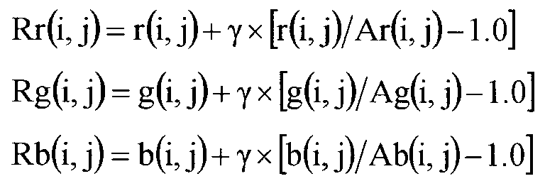
なお、コントラスト調整量VRPij(Rr(i,j),Rg(i,j),Rb(i,j))の定義は一律ではなく、例えば(数7)のように、各成分ごとの画素値VPijの加重平均画素値VAPijに対する比から1.0を減算した値に予め設定された正定数γを乗算した値を入力画像の画素値VPij(r(i,j),g(i,j),b(i,j))に加算した値を改めてコントラスト調整量VRPij(Rr(i,j),Rg(i,j),Rb(i,j))として定義することも可能である。 Note that the definition of the contrast adjustment amount VRPij (Rr (i, j), Rg (i, j), Rb (i, j)) is not uniform. For example, as in (Equation 7), the pixel value for each component The value obtained by subtracting 1.0 from the ratio of VPij to the weighted average pixel value VAPij multiplied by a preset positive constant γ is the pixel value VPij (r (i, j), g (i, j)) of the input image. , B (i, j)) can be redefined as the contrast adjustment amount VRPij (Rr (i, j), Rg (i, j), Rb (i, j)).
こうすることで、従来の技術でも問題とした、c画素の周辺視野内で画素値変動が非常に小さい場合にコントラスト調整量VRPij(Rr(i,j),Rg(i,j),Rb(i,j))の各成分はVPij(r(i,j),g(i,j),b(i,j))に関係なく1.0近傍になってしまうことを避けることができるという利点があるが、設定されたγによる依存性があることに注意する必要がある。また、これらの処理は、本実施例(実施の形態)による画像処理方法に従い、コンピュータ等に使用される中央演算処理装置(CPU)及びディジタルシグナルプロセッサ(DSP)等を使ったソフトウェア処理でも同様に実現することができる。 By doing so, the contrast adjustment amounts VRPij (Rr (i, j), Rg (i, j), Rb () when the pixel value variation is very small in the peripheral visual field of the c pixel, which is a problem in the conventional technique, i, j)) each component of VPij (r (i, j), g (i, j), b (i, j)) can be avoided from being in the vicinity of 1.0. Although there is an advantage, it should be noted that there is a dependency due to the set γ. These processes are also performed by software processing using a central processing unit (CPU) and a digital signal processor (DSP) used in a computer or the like according to the image processing method according to the present embodiment (embodiment). Can be realized.
本発明の実施例(実施の形態)2による画像処理装置の基本構成は実施例(実施の形態)1と同様、図1の構成であり、また画像処理手段11も図2(a)のようにコントラスト調整手段20になる。その際、コントラスト調整手段20は図4のような構成になる。 The basic configuration of the image processing apparatus according to the embodiment (embodiment) 2 of the present invention is the configuration of FIG. 1 as in the embodiment (embodiment) 1, and the image processing means 11 is also as shown in FIG. Thus, the contrast adjusting means 20 is obtained. At that time, the contrast adjusting means 20 is configured as shown in FIG.
図4において、補正情報導出手段30、抽出手段31、画素値変換手段32は図3と同様のものなので、同一符号を付し、説明は省略する。40は補正情報導出(対象画素のコントラスト調整量算出)を行う際の初期条件を設定する初期設定手段である。初期設定手段40は、主に中央視野である対象画素Pijと比較する周辺視野部の大きさcに初期周辺領域サイズc0を設定する処理を行う。また、41は予め用意された複数の周辺視野領域すべてでコントラスト調整量が算出されたかどうかを判定する終了判定条件、42は終了判定条件41で終了判定と見なされなかった場合に現在処理している周辺視野領域の大きさcを次の候補に変更する補正範囲変更手段である。なお、画像合成手段12は実施例(実施の形態)1と同様に図10のように構成されている。
In FIG. 4, the correction information deriving means 30, the extracting
以上のように構成された画像処理装置について、その動作を図10、図14、図15を用いて説明する。図14は周辺視野領域を模式的に示す説明図、図15はコントラスト調整手段20における動作を示すフローチャートである。 The operation of the image processing apparatus configured as described above will be described with reference to FIG. 10, FIG. 14, and FIG. FIG. 14 is an explanatory diagram schematically showing the peripheral visual field region, and FIG.
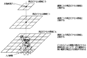
画像入力手段10を介して、画像処理手段11に、カラー画像viがディジタル入力される。画像入力手段10では、カラー画像の場合、通常レッドr、グリーンg、ブルーbの成分データが画像入力手段10の精度で(8ビットならば0から255の値で)得られる。画像入力手段10では、この値を0.0から1.0の値に正規化する。次に、ディジタル入力画像に対して、入力画像の暗部におけるコントラストを改善するためのコントラスト調整処理がコントラスト調整手段20で行われる。コントラスト調整手段20では図15のように行われる。本実施例(実施の形態)の特徴は、実施例(実施の形態)1に対して、図14で模式的に示されるように、複数用意された周辺視野領域でのコントラスト調整を行うことで、画像内に存在する暗部(影)の大きさによる影響を低減するようにした点である。
The color image vi is digitally input to the
次に、コントラスト調整手段20について、その動作を図15を用いて説明する。
Next, the operation of the
図15において、まず、初期設定手段40は、入力画像内における画素Pijの各成分の最大値Vmax(rx,gx,bx)と最小値Vmin(rn,gn,bn)を算出する(S21)。次に、対象画素Pijの画素値VPijをLandにおける中心視野と見なし、その周囲にc画素の矩形領域に属する領域を周辺視野と見なす。その際、初期設定手段40で、まずc=c0というように、予め用意された複数の周辺視野領域サイズck(k=0,1,・・・,Cnum−1)内でc0を周辺視野領域として設定する。この場合、ckは最小サイズ領域から昇順に用意しても構わないし、最大サイズから降順に用意しても構わないが、サイズの変更方向をそろえた方がよい。ここでは最大サイズから降順に用意されているとして、順に周辺視野領域を小さいくしながら、入力画像における細部改善を行うこととする。次に、補正情報導出手段30では、現在設定されているc=ckの矩形域の周辺視野に対して、周辺視野における画素値の加重平均画素値VAPij_k(Ar_k(i,j),Ag_k(i,j),Ab_k(i,j))が算出される(S22)。そして、すべてのckで補正情報導出手段30での画素Pij周辺視野における加重平均画素値計算が終了したかどうかの判定を終了判定手段41で行う(S23)。終了していないと判定された場合には補正情報範囲変更手段42へ処理が移り、現在設定されている周辺視野領域cをつぎの候補に変更し、再び補正情報導出手段30での加重平均画素値算出が行われる。一方、終了判定手段41で終了判定された場合には、補正情報導出手段30は、各周辺視野領域ckに対するPijの加重平均画素値VAPij_k(Ar_k(i,j),Ag_k(i,j),Ab_k(i,j))の重み付き平均値を求め、その値をPijの全加重平均画素値VAPij(Ar(i,j),Ag(i,j),Ab(i,j))と設定する(S24)。その際、周辺視野領域ckの大きさに応じた重み付けを各ckによるPijの加重平均画素値に付加することが考えられるが、ここでは簡易化のために、各ckによる加重平均画素値VAPij_kの平均画素値をPijの全加重平均画素値として採用する。そして、補正情報導出手段30は、Pijにおける各成分ごとの画素値VPijの全加重平均画素値VAPijに対する比をコントラスト調整量VRPij(Rr(i,j),Rg(i,j),Rb(i,j))として算出する(S25)。
In FIG. 15, first, the initial setting means 40 calculates the maximum value Vmax (rx, gx, bx) and the minimum value Vmin (rn, gn, bn) of each component of the pixel Pij in the input image (S21). Next, the pixel value VPij of the target pixel Pij is regarded as a central visual field in Land, and a region belonging to a rectangular region of c pixels around it is regarded as a peripheral visual field. At that time, the initial setting means 40 first sets c0 as the peripheral visual field area within a plurality of peripheral visual field area sizes ck (k = 0, 1,..., Cnum−1) prepared in advance, such as c = c0. Set as. In this case, ck may be prepared in ascending order from the minimum size area, or may be prepared in descending order from the maximum size, but it is better to align the direction of size change. Here, assuming that the images are prepared in descending order from the maximum size, it is assumed that the detail improvement in the input image is performed while the peripheral visual field region is sequentially reduced. Next, in the correction
これ以降の処理は実施例(実施の形態)1と同様に、まず、コントラスト調整量VRPijより抽出される際の最小値eminと最大値emaxを導出する(S26、S27、S28)。次に、このemaxとeminを使って、コントラスト調整量VRPij(Rr(i,j),Rg(i,j),Rb(i,j))の各成分を0.0から1.0の範囲内の値に変換し(S29)、変換値を入力画像のVmax(rx,gx,bx)と最小値Vmin(rn,gn,bn)内に抑える(S30)。こうして得られたコントラスト調整量VRPijを対象画素Pijにおけるコントラスト調整の画素値と見なして(S30)、コントラスト調整処理が終了する(S30a)。 In the subsequent processing, as in Example (Embodiment) 1, first, a minimum value emin and a maximum value emax are derived when extracted from the contrast adjustment amount VRPij (S26, S27, S28). Next, using emax and emin, each component of the contrast adjustment amount VRPij (Rr (i, j), Rg (i, j), Rb (i, j)) is in the range of 0.0 to 1.0. (S29), and the converted value is suppressed to Vmax (rx, gx, bx) and the minimum value Vmin (rn, gn, bn) of the input image (S30). The contrast adjustment amount VRPij obtained in this way is regarded as the pixel value for contrast adjustment in the target pixel Pij (S30), and the contrast adjustment processing is ended (S30a).
また、画像合成処理部も実施例(実施の形態)1と同様に、入力画像1のPijにおける輝度値y(i,j)と処理済画像3の対応する画素での輝度値yd(i,j)より得られた結合係数w1とw3を使って、Pijにおける入力画像viの画素値VPijと処理済画像vの画素値VRPijの加重平均画素値VWPij(WRr(i,j),WRg(i,j),WRb(i,j))が求められ、処理済み画像vの対応する画素位置Pijに埋め込まれる。このような処理が全画素に対して行うことで、最終的に画像出力手段13で出力される出力画像voが生成される。
Similarly to the embodiment (embodiment) 1, the image composition processing unit also uses the luminance value y (i, j) in Pij of the
以上のような構成や処理を行うことで本実施例(実施の形態)である画像処理装置は、実施例(実施の形態)1による画像処理装置の特徴を生かしながら、入力画像における画素値のダイナミックレンジや影のような暗部サイズにあまり影響されることなく、自動的に入力画像のコントラスト調整を行うことができ、画像のコントラスト調整の効率化につながる。なお、これらの処理は、本実施例(実施の形態)による画像処理方法に従い、コンピュータ等に使用される中央演算処理装置(CPU)及びディジタルシグナルプロセッサ(DSP)等を使ったソフトウェア処理でも同様に実現することができる。 By performing the configuration and processing as described above, the image processing apparatus according to the present embodiment (embodiment) takes advantage of the characteristics of the image processing apparatus according to the embodiment (embodiment) 1 and changes the pixel values in the input image. The contrast of the input image can be automatically adjusted without being greatly affected by the size of the dark part such as the dynamic range and shadow, which leads to the efficiency of the image contrast adjustment. These processes are also performed by software processing using a central processing unit (CPU) and a digital signal processor (DSP) used in a computer or the like according to the image processing method according to the present embodiment (embodiment). Can be realized.
本発明の実施例(実施の形態)3による画像処理装置の基本構成は実施例(実施の形態)1と同様、図1の構成である。また、画像処理手段11も図2(a)のようにコントラスト調整手段20が採用されている。その際、コントラスト調整手段20は図5のような構成になる。図5は本実施例(実施の形態)による画像処理装置を構成するコントラスト調整手段20を示すブロック図である。 The basic configuration of the image processing apparatus according to the embodiment (embodiment) 3 of the present invention is the same as that of the embodiment (embodiment) 1 as shown in FIG. The image processing means 11 also employs contrast adjustment means 20 as shown in FIG. At that time, the contrast adjusting means 20 is configured as shown in FIG. FIG. 5 is a block diagram showing the contrast adjusting means 20 constituting the image processing apparatus according to the present embodiment (embodiment).
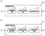
図5において、31は図3と同様の抽出手段、50は入力画像vi内の画素値をコントラスト調整時の対象とする信号(対象信号)へ変換する信号変換手段、51は信号変換手段50で得られた対象信号に対して、対象画素Pijのコントラスト調整量を求める対象補正情報導出手段、52は抽出手段31で抽出されたコントラスト調整量に基づいて、信号変換手段50で得られた対象信号を実際の対象信号(調整済みの対象信号)に変換する対象信号変換手段、53は対象信号変換手段52で得られた調整済みの対象信号と信号変換手段50で得られたそれ以外の信号(対象信号)とにより調整済みの対象信号の実際の画素値への逆変換処理を行う信号逆変換手段である。 In FIG. 5, 31 is extraction means similar to FIG. 3, 50 is signal conversion means for converting the pixel value in the input image vi into a signal (target signal) to be subjected to contrast adjustment, and 51 is signal conversion means 50. Target correction information deriving means for obtaining the contrast adjustment amount of the target pixel Pij with respect to the obtained target signal, 52 is a target signal obtained by the signal conversion means 50 based on the contrast adjustment amount extracted by the extraction means 31 Is converted into an actual target signal (adjusted target signal), 53 is an adjusted target signal obtained by the target signal conversion means 52 and other signals obtained by the signal conversion means 50 ( Signal reverse conversion means for performing reverse conversion processing of the target signal adjusted with the target signal) to the actual pixel value.
本実施例(実施の形態)の特徴は、カラー画像の画素Pijにおける画素値VPij(r(i,j),g(i,j),b(i,j))を他の複数信号に変換し、その内の1つの信号に対して実施例(実施の形態)1と同様にコントラスト調整量を算出し、最後に調整された対象信号のコントラスト調整量と入力画像viより変換時にそのまま保持された他の信号とから信号変換手段50で行われた変換処理の逆変換処理を行うことで、図1における処理済画像の画素Pijにおける画素値を求める点である。ここで、信号変換手段50において、Pijの画素値VPij(r(i,j),g(i,j),b(i,j))から例えば明度L(i,j)と色相a*(i,j),b*(i,j)に変換し、この明度L(i,j)をコントラスト調整時の対象信号にする。そして、他の色相信号を入力画像のまま保持することで、本実施例(実施の形態)では、明度のレベルを制御しながら、入力画像における色情報をそのまま保持することができるため、コントラスト調整手段20で得られた処理済み画像vの色バランスは入力画像をそのまま再現することが出来るとともに、対象補正情報導出手段51での周辺視野領域と対象画素での比較処理量を軽減することができる。
A feature of the present embodiment (embodiment) is that the pixel value VPij (r (i, j), g (i, j), b (i, j)) in the pixel Pij of the color image is converted into other plural signals. Then, the contrast adjustment amount is calculated for one of the signals in the same manner as in the first embodiment (embodiment), and is maintained as it is at the time of conversion from the contrast adjustment amount of the last adjusted target signal and the input image vi. The pixel value in the pixel Pij of the processed image in FIG. 1 is obtained by performing an inverse conversion process of the conversion process performed by the
以上のように構成された画像処理装置について、その動作を図16を用いて説明する。図16は図5のコントラスト調整手段20の動作を示すフローチャートである。 The operation of the image processing apparatus configured as described above will be described with reference to FIG. FIG. 16 is a flowchart showing the operation of the contrast adjusting means 20 of FIG.
図16において、まず、入力画像1の画素PijにおけるVPij(r(i,j),g(i,j),b(i,j))をLa*b*空間における信号VPLij(L(i,j),a*(i,j),b*(i,j))に信号変換手段50で変換するとともに、Pijにおける変換値信号の内、色相a*(i,j)とb*(i,j)を保持する(S31)。これ以降、対象補正情報導出手段51から対象信号変換手段52までの処理は明度L(i,j)を対象信号として処理が行われる。なお、L(i,j)は0.0から1.0に正規化されているものとする。これにより、入力画像viの持つ色情報のバランスを処理済み画像vでも精度よく保持することができると考えられる。対象補正情報導出手段51は、入力画像の画素Pijの明度L(i,j)の最大値Lxと最小値Lnを算出する(S32)。次に、対象画素Pijの周辺視野における明度L(i,j)の加重平均明度AL(i,j)を求めるとともに(S33)、L(i,j)とAL(i,j)に対する比を明度のコントラスト調整量RL(i,j)として算出する(S34)。以上のような対象画素Pijに対する明度のコントラスト調整量RL(i,j)の算出が入力画像内の全ての画素に対して対象補正情報導出手段51で行われる。抽出手段31では、明度のコントラスト調整量RL(i,j)の平均値aRLと標準偏差量dRLを求め(S36)、その値により明度のコントラスト調整量RL(i,j)より抽出される際の最小値eminと最大値emaxを決定する(S37)。対象信号変換手段52は、このemaxとeminを使って、明度のコントラスト調整量RL(i,j)を0.0から1.0の範囲内の値に変換し(S38)、その変換値を入力画像の最大値Lxと最小値Ln内に抑える処理を行う(S39)。信号逆変換手段53では、こうして得られた明度のコントラスト調整量RL(i,j)を対象画素Pijにおける明度のコントラスト調整値と見なすとともに、保持されていた色相a*(i,j)とb*(i,j)を使って、処理済み画像vの画素Pijにおける画素値VRPij(Rr(i,j),Rg(i,j),Rb(i,j))を信号変換手段50で用いた信号変換の逆変換により求めることで(S40)、コントラスト調整済み画像vを生成する(S40a)。なお、信号逆変換手段53において明度のコントラスト調整量RL(i,j)は0.0から1.0の範囲の値に変換されているため、1度色相a*(i,j)とb*(i,j)と合わせて逆変換する際の信号レベルに戻すことも必要になる。
In FIG. 16, first, VPij (r (i, j), g (i, j), b (i, j)) in the pixel Pij of the
このような一連の処理を取ることで、本実施例(実施の形態)である画像処理装置は、従来や実施例(実施の形態)1、2のようにカラー画像で3画素独立にコントラスト調整した場合に比べて、入力画像内の画素の持つ色バランスを保持しやすくなり、調整により得られた画像における影のような暗部での色の安定性をより保つことができる。さらに、対象補正情報導出手段51における対象画素と周辺視野内の画素との相対的比較で算出されるコントラスト調整量は、従来の技術や実施例(実施の形態)1、2では3成分独立に算出する必要があったのに対し、明度1成分ですむため、大幅な処理時間の短縮化につながる。また、これらの処理は、実施例(実施の形態)3による画像処理方法に従い、コンピュータ等に使用される中央演算処理装置(CPU)及びディジタルシグナルプロセッサ(DSP)等を使ったソフトウェア処理でも同様に実現することができる。 By taking such a series of processes, the image processing apparatus according to the present embodiment (embodiment) can adjust contrast independently for three pixels in a color image as in the prior art and embodiments (embodiments) 1 and 2. Compared to the case, it becomes easier to maintain the color balance of the pixels in the input image, and the stability of the color in a dark part such as a shadow in the image obtained by the adjustment can be further maintained. Further, the contrast adjustment amount calculated by the relative comparison between the target pixel in the target correction information deriving means 51 and the pixel in the peripheral visual field is independent of the three components in the conventional technique and the embodiments (embodiments) 1 and 2. Although it was necessary to calculate, only one component of brightness is required, leading to a significant reduction in processing time. These processes are also performed by software processing using a central processing unit (CPU) and a digital signal processor (DSP) used in a computer or the like according to the image processing method according to the third embodiment (embodiment). Can be realized.
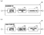
本発明の実施例(実施の形態)4による画像処理装置の基本構成は実施例(実施の形態)1と同様、図1の構成である。また、画像処理手段11も図2(a)のようにコントラスト調整手段20が採用されている。その際、コントラスト調整手段20は図6のような構成になる。 The basic configuration of the image processing apparatus according to the embodiment (embodiment) 4 of the present invention is the same as that of the embodiment (embodiment) 1 as shown in FIG. The image processing means 11 also employs contrast adjustment means 20 as shown in FIG. At that time, the contrast adjusting means 20 is configured as shown in FIG.
図6は本実施例(実施の形態)による画像処理装置を構成するコントラスト調整手段20を示すブロック図である。図6において、信号変換手段50、補記設定手段40、対象補正情報導出手段51、補正範囲変更手段42、終了判定手段41、抽出手段31、対象信号変換手段52、信号逆変換手段53は図3〜図5と同様のものなので、同一符号を付し、説明は省略する。図6より明らかのように、実施例(実施の形態)2における複数の周辺視野を持つコントラスト調整処理に、実施例(実施の形態)3におけるコントラスト調整手段におけるコントラスト調整処理を対象信号のみに限定した工夫を加えたものである。 FIG. 6 is a block diagram showing the contrast adjusting means 20 constituting the image processing apparatus according to the present embodiment (embodiment). In FIG. 6, the signal conversion means 50, the supplementary note setting means 40, the target correction information derivation means 51, the correction range change means 42, the end determination means 41, the extraction means 31, the target signal conversion means 52, and the signal reverse conversion means 53 are shown in FIG. Since it is the same as that shown in FIG. As apparent from FIG. 6, the contrast adjustment processing in the contrast adjustment means in Example (Embodiment) 3 is limited to the target signal only in contrast adjustment processing having a plurality of peripheral visual fields in Example (Embodiment) 2. It is something that has been added.
図6のコントラスト調整手段20について、その動作を図17を用いて説明する。図17は図6のコントラスト調整手段20の動作を示すフローチャートである。
The operation of the
図17において、まず、画像入力手段10で入力された入力画像viの画素PijにおけるVPij(r(i,j),g(i,j),b(i,j))は信号変換手段50でLa*b*空間における信号VPLij(L(i,j),a*(i,j),b*(i,j))に変換され、Pijにおける変換値信号の内、色相a*(i,j)とb*(i,j)が保持され、L(i,j)は0.0から1.0に正規化される(S41)。対象補正情報導出手段51は、入力画像の画素Pijの明度L(i,j)の最大値Lxと最小値Lnを算出する(S42)。次に、対象補正情報導出手段51は、この明度L(i,j)を対象信号として、実施例(実施の形態)2と同様に、複数の周辺視野領域ck(k=0,1,・・・,Cnum−1)の加重平均明度AL_k(i,j)を求める(S43)。そして、終了判定手段41が、所定の周辺視野領域全部に対する加重平均明度の算出が終了したと判定した時点で(S44)、対象補正情報導出手段51は、それらの重みつき平均値が全加重平均明度AL(i,j)とされ(S45)、その値に対するL(i,j)の比を明度のコントラスト調整量RL(i,j)として算出する(S46)。終了判定手段41が全画素終了と判定すると(S47)、抽出手段31では、明度のコントラスト調整量RL(i,j)の平均値aRLと標準偏差量dRLが求められ(S48)、その値により決定された明度のコントラスト調整量RL(i,j)の最小値eminと最大値emaxを使って、明度のコントラスト調整量RL(i,j)は0.0から1.0の範囲内の値に変換される(S49、S50)。その変換値は、入力画像の最大値Lxと最小値Ln内に抑えられ、信号逆変換手段53では、こうして得られた明度のコントラスト調整量RL(i,j)を対象画素Pijにおける明度のコントラスト調整値と見なすとともに(S51)、保持されていた色相a*(i,j)とb*(i,j)を使って、処理済み画像3の画素Pijにおける画素値VRPij(Rr(i,j),Rg(i,j),Rb(i,j))を求めることで(S52)、コントラスト調整済み画像vを生成する(S53)。
In FIG. 17, first, VPij (r (i, j), g (i, j), b (i, j)) in the pixel Pij of the input image vi inputted by the image input means 10 is obtained by the signal conversion means 50. It is converted into a signal VPLij (L (i, j), a * (i, j), b * (i, j)) in the La * b * space, and the hue a * (i, j) and b * (i, j) are retained, and L (i, j) is normalized from 0.0 to 1.0 (S41). The target correction
以上のように本実施例(実施の形態)による画像処理装置は、実施例(実施の形態)3で対象画素値とその周辺領域における平均画素値との比較により算出したコントラスト調整量を複数の周辺領域でのコントラスト調整量の加重平均値に拡張したものであり、実施例(実施の形態)2の特徴である周辺視野領域を予め決定する必要がない利点と、実施例(実施の形態)3のように画素の持つ色バランスを保持しやすくなり、調整により得られた画像における影のような暗部での色の安定性をより保つことができる。また、処理の簡易化につながり処理時間の短縮化も可能となる利点を持つ。 As described above, the image processing apparatus according to the present embodiment (embodiment) uses a plurality of contrast adjustment amounts calculated by comparing the target pixel value with the average pixel value in the surrounding area in the embodiment (embodiment) 3. This is an extension to the weighted average value of the contrast adjustment amount in the peripheral area, and there is an advantage that it is not necessary to predetermine the peripheral visual field area, which is a feature of the embodiment (embodiment) 2, and the embodiment (embodiment). As shown in FIG. 3, the color balance of the pixels can be easily maintained, and the color stability in a dark portion such as a shadow in the image obtained by the adjustment can be further maintained. In addition, there is an advantage that processing is simplified and processing time can be shortened.
さらに、これらの処理は、実施例(実施の形態)4であるカラー画像処理方法に従い、コンピュータ等に使用される中央演算処理装置(CPU)及びディジタルシグナルプロセッサ(DSP)等を使ったソフトウェア処理でも同様に実現することができる。 Further, these processes are performed by software processing using a central processing unit (CPU) and a digital signal processor (DSP) used in a computer or the like according to the color image processing method according to the fourth embodiment (embodiment). It can be realized similarly.
本発明の実施例(実施の形態)5による画像処理装置の基本構成は実施例(実施の形態)1と同様、図1の構成である。また、画像処理手段11も図2(a)のようにコントラスト調整手段20が採用され、さらにコントラスト調整手段20は図3のような構成になる。本実施例(実施の形態)が実施例(実施の形態)1と異なる点は、図3におけるコントラスト調整手段20内の画素値変換手段32が図7(a)のように構成されていることである。 The basic configuration of an image processing apparatus according to Example (Embodiment) 5 of the present invention is the same as that of Example (Embodiment) 1 as shown in FIG. Further, the image processing means 11 employs the contrast adjusting means 20 as shown in FIG. 2A, and the contrast adjusting means 20 has a configuration as shown in FIG. This embodiment (embodiment) is different from embodiment (embodiment) 1 in that the pixel value conversion means 32 in the contrast adjustment means 20 in FIG. 3 is configured as shown in FIG. It is.
図7(a)は、本実施例(実施の形態)による画素値変換手段32を示すブロック図である。図7(a)に示されるように、画素値変換手段32は、入力画像vi内の平均輝度を算出する平均輝度算出手段70と、平均輝度算出手段70で得られた平均輝度をもとに、抽出手段31で得られたコントラスト調整量を実際の画素値に変換する際の変換方式を選択する変換方式分類手段71と、変換方式分類手段71で得られた変換方式に従い、抽出手段31で得られたコントラスト調整量を実際の画素の持つ画素値に変換する画素値推定手段72とを構成要素として持つ。本実施例(実施の形態)の特徴は、実施例(実施の形態)1に、入力画像の輝度をもとに、周辺視野内の画素との相対的比較で得られた値を実際の画素値に変換する際の変換方式を選択するものである。
FIG. 7A is a block diagram showing the pixel value conversion means 32 according to the present embodiment (embodiment). As shown in FIG. 7A, the pixel
図3におけるコントラスト調整手段20において、画素値変換手段32以外の処理の流れは実施例(実施の形態)1と同様に、入力画像内の画素Pijにおいて、その画素値をc画素の周辺視野領域における加重平均画素値で除することで、まずコントラスト調整量を求める。そして、このコントラスト調整量から、有効となる領域が、コントラスト調整量を構成する各成分のヒストグラム分布をもとに抽出され、各成分ともに0.0から1.0内の値に変換される。この後で図12のステップS8のかわりに画素値変換手段32における画素値変換処理が実行されるのであるが、その処理は、図18のようになる。
In the
次に、図7(a)の画素値変換手段32について、その動作を図18を用いて説明する。図18は図7(a)の画素値変換手段32の動作を示すフローチャートである。 Next, the operation of the pixel value conversion means 32 in FIG. 7A will be described with reference to FIG. FIG. 18 is a flowchart showing the operation of the pixel value conversion means 32 in FIG.
図18において、まず、平均輝度算出手段70は、入力画像内の画素Pijの輝度y(i,j)を計算し、その輝度平均ave_yを求める(S61)。次に、変換方式分類手段71は、このave_yの値でコントラスト調整量が実際の画素値に変換される方式を選択する。その場合、多くの手法が考えられるが、ここでは低輝度しきい値Th_lowと高輝度しきい値Th_highを設け、(数8)のようにコントラスト調整量を実際の画素値成分に変換する際の変換関数gg(x)を選択することとした(S62〜S66)。
In FIG. 18, first, the average luminance calculating means 70 calculates the luminance y (i, j) of the pixel Pij in the input image and obtains the average luminance ave_y (S61). Next, the conversion
なお、(数8)でk_l,g_l,g_n,k_h,g_hは予め設定された定数であり、Xは変換される前のコントラスト調整量の対象成分値を示す。これは、処理前の入力画像における平均輝度をもとに、その重点すべき部分を決めるものである。例えば、入力画像全体が低い輝度の場合、全体が急激に明るくなるよりも低輝度部分をできるだけ残す方が立体感の観点からも印象がよい。また、入力画像全体が高い輝度の場合、高輝度部分に対する人間の注目度は高く、その部分をできるだけ保持することも必要である。そして、自然画像のように中間輝度を持つ場合は、中心より低い輝度部分をやや暗くし、中心より高い輝度をやや明るくする手法がプリンタ出力等の時の入出力値のガンマ変換で行われる。ここでの処理はこれらの知見に従ったものであり、このような知見に沿う変換方式であれば、ここで示す方式に一律に決まるものではなく同様に使用することができると思われる。最後に、画素値推定手段72が変換方式分類手段71で選択された変換関数を使って、抽出手段31で抽出されたコントラスト調整量VRPij(Rr(i,j),Rg(i,j),Rb(i,j))の各成分の変換値VRPoij(Rro(i,j),Rgo(i,j),Rbo(i,j))を求める(S67、S68)。これを、入力画像内における画素Pijの各成分の最大値Vmax(rx,gx,bx)と最小値Vmin(rn,gn,bn)内に抑え、処理済み画像vの画素Pijにおける調整済み画素値として設定することで処理済画像vを得るのである(S69、S70)。この画像vと入力画像viの加重平均画像を画像合成手段12が求め、これが最終的に出力される出力画像voとなる。
In
以上のように実施例(実施の形態)5による画像処理装置は、実施例(実施の形態)1の画素値変換手段32において、周囲画素との比較で得られたコントラスト調整量から有効と思われる領域を抽出した後に、入力画像における平均輝度をもとに、抽出されたコントラスト調整量を変換する変換方式を選択し適用する画素値推定手段72を設けたものである。こうすることで、入力画像内の輝度分布に応じて適切な画素値変換を選択することが可能となり、より調整後の画像におけるコントラスト調整を高めることが可能となる。
As described above, the image processing apparatus according to Example (Embodiment) 5 seems to be effective from the contrast adjustment amount obtained by comparison with surrounding pixels in the pixel
なお、この実施例(実施の形態)ではコントラスト調整手段として実施例(実施の形態)1で説明した図3の構成の場合で説明したが、図4のように複数の周辺視野領域を持つ実施例(実施の形態)2で用いられたコントラスト調整手段に本実施例(実施の形態)における画素値変換手段を組み合わせることも可能である。さらに、これらの処理は、実施例(実施の形態)5による画像処理方法に従い、コンピュータ等に使用される中央演算処理装置(CPU)及びディジタルシグナルプロセッサ(DSP)等を使ったソフトウェア処理でも同様に実現することができる。 In this embodiment (embodiment), the contrast adjusting means is described in the case of the configuration of FIG. 3 described in embodiment (embodiment) 1. However, as shown in FIG. It is also possible to combine the pixel value conversion means in this example (embodiment) with the contrast adjustment means used in Example (embodiment) 2. Further, these processes are also performed by software processing using a central processing unit (CPU) and a digital signal processor (DSP) used in a computer or the like according to the image processing method according to the embodiment (embodiment) 5. Can be realized.
本発明の実施例(実施の形態)6による画像処理装置の基本構成は実施例(実施の形態)1と同様、図1の構成である。画像処理手段11として設定されたコントラスト調整手段は図5のような構成になる。実施例(実施の形態)6が実施例(実施の形態)3と異なる点は、図5におけるコントラスト調整手段20内の対象信号変換手段52が図7(b)のように構成されていることである。 The basic configuration of an image processing apparatus according to Example (Embodiment) 6 of the present invention is the same as that of Example (Embodiment) 1 as shown in FIG. The contrast adjusting means set as the image processing means 11 has a configuration as shown in FIG. The difference between Example (Embodiment) 6 and Example (Embodiment) 3 is that target signal conversion means 52 in contrast adjustment means 20 in FIG. 5 is configured as shown in FIG. 7B. It is.
図7(b)は、図5の対象信号変換手段52を示すブロック図である。 FIG. 7B is a block diagram showing the target signal conversion means 52 of FIG.
図7(b)に示されるように、対象信号変換手段52は、入力画像vi内の平対象信号の平均値を算出する平均対象信号算出手段73と、平均対象信号算出手段73で得られた対象信号の平均値をもとに、抽出手段31で得られた対象信号のコントラスト調整量を実際の対象信号値に変換する際の変換方式を選択する変換方式分類手段71と、変換方式分類手段71で得られた変換方式に従い、抽出手段31で得られた対象信号のコントラスト調整量を実際の対象信号値に変換する対象信号推定手段74とを構成要素として持つ。この実施例(実施の形態)の特徴は、実施例(実施の形態)3に、入力画像の対象信号をもとに、周辺視野内の対象信号との相対的比較で得られた値を実際の対象信号値に変換する際の変換方式を選択するものである。
As shown in FIG. 7B, the target
本実施例(実施の形態)におけるコントラスト調整処理の流れは、実施例(実施の形態)3を表す図16とほぼ同じように処理される。実施例(実施の形態)3と比べると図16のステップS40のかわりに図7(b)の対象信号変換手段74の処理が付加されていることが異なる。この図7(b)における対象信号変換手段74での処理は、実施例(実施の形態)5で用いられた図7(a)の画素値変換手段32での処理を対象信号である明度に対して行うように変更したものが行われる。つまり、図18で示された実施例(実施の形態)5の画素値変換処理に対して、本実施例(実施の形態)では対象信号に対してのみ変換関数が適用される点と、抽出手段31で抽出されたコントラスト調整量の変換方式の選択に実施例(実施の形態)5では入力画像の平均輝度を用いたが、本実施例(実施の形態)では信号変換手段50で入力画像より得られた明度、色相のうちで対象信号とされた明度の平均値が用いられている点が異なる。このように対象信号の平均値が抽出手段31で抽出されたコントラスト調整量の変換方式の選択に使用されている理由として、元々実施例(実施の形態)3では、コントラスト調整量の算出は信号変換手段50で得られた明度に対してのみ行われ、対象信号変換手段52を介して得られた調整後の画素(i,j)の明度RL(i,j)と信号変換手段50で得られた色相を逆変換することで所望のコントラスト調整済み画像vを得ているため、処理の簡易化の点から、そして明度が輝度と同じような意味を持つ点が挙げられる。
The flow of contrast adjustment processing in the present embodiment (embodiment) is processed in substantially the same manner as in FIG. 16 representing the embodiment (embodiment) 3. Compared to Example (Embodiment) 3, the processing of the target signal conversion means 74 of FIG. 7B is added instead of step S40 of FIG. The processing in the target signal conversion means 74 in FIG. 7B is performed by changing the processing in the pixel value conversion means 32 in FIG. 7A used in the embodiment (embodiment) 5 to the lightness that is the target signal. What has been changed to be performed on is performed. That is, in contrast to the pixel value conversion processing of Example 5 (Embodiment) 5 shown in FIG. 18, the conversion function is applied only to the target signal in this Example (Embodiment), and extraction is performed. In the embodiment (embodiment) 5, the average luminance of the input image is used to select the conversion method of the contrast adjustment amount extracted by the
このような本実施例(実施の形態)による画像処理装置は、実施例(実施の形態)3の対象信号変換手段50において、周囲画素との比較で得られた明度のコントラスト調整量から有効と思われる領域を抽出した後に、入力画像における平均明度をもとに、抽出された対象信号のコントラスト調整量を変換する変換方式を選択し適用するものである。よって、本実施例(実施の形態)は実施例(実施の形態)3のように画素の色安定を高めるとともに、実施例(実施の形態)5におけるコントラストのより高精度化を進めるためのものである。 Such an image processing apparatus according to the present embodiment (embodiment) is effective from the contrast adjustment amount of brightness obtained by comparison with surrounding pixels in the target signal conversion means 50 of the embodiment (embodiment) 3. After extracting a possible region, a conversion method for converting the contrast adjustment amount of the extracted target signal is selected and applied based on the average brightness in the input image. Therefore, the present embodiment (embodiment) is for improving the color stability of the pixel as in the embodiment (embodiment) 3 and further improving the accuracy of the contrast in the embodiment (embodiment) 5. It is.
なお、本実施例(実施の形態)では、コントラスト調整手段20として実施例(実施の形態)3で説明した図5の構成の場合で説明したが、図6のように複数の周辺視野領域を持つ実施例(実施の形態)4で用いられたコントラスト調整手段20に本実施例(実施の形態)における対象信号変換手段52を組み合わせることも可能である。さらに、これらの処理は、本実施例(実施の形態)による画像処理方法に従い、コンピュータ等に使用される中央演算処理装置(CPU)及びディジタルシグナルプロセッサ(DSP)等を使ったソフトウェア処理でも同様に実現することができる。 In the present embodiment (embodiment), the contrast adjusting means 20 has been described in the case of the configuration of FIG. 5 described in the embodiment (embodiment) 3. However, as shown in FIG. It is also possible to combine the target signal conversion means 52 in the present embodiment (embodiment) with the contrast adjustment means 20 used in the embodiment 4 (embodiment). Further, these processes are also performed by software processing using a central processing unit (CPU) and a digital signal processor (DSP) used in a computer or the like according to the image processing method according to the present embodiment (embodiment). Can be realized.
本発明の実施例(実施の形態)7による基本的構成は実施例(実施の形態)1と同様、図1の構成である。画像処理手段11であるコントラスト調整手段20は図3のような構成になる。図3のようにコントラスト調整手段21は補正情報導出手段30、抽出手段31、画素値変換手段32より構成されている。
The basic configuration according to the embodiment (embodiment) 7 of the present invention is the configuration shown in FIG. The contrast adjusting means 20 which is the image processing means 11 has a configuration as shown in FIG. As shown in FIG. 3, the contrast adjusting unit 21 includes a correction
図8(a)は画像変換手段32を示すブロック図である。画像変換手段32は図8(a)のように、入力画像vi内のコントラスト情報を表す輝度エッジ強度を算出する基準強度算出手段80と、抽出手段31で得られたコントラスト調整量を実際の画素値に変換する際の変換曲線を遺伝的アルゴリズムで推定する変換曲線推定手段81と、変換曲線推定手段81で推定された画素値の変換曲線をもとに、抽出手段31で得られたコントラスト調整量を実際の画素値に変換する画素値推定手段72とを構成要素として持つ。
FIG. 8A is a block diagram showing the image conversion means 32. As shown in FIG. 8A, the image conversion means 32 uses the reference intensity calculation means 80 for calculating the luminance edge intensity representing the contrast information in the input image vi, and the contrast adjustment amount obtained by the extraction means 31 as the actual pixel. A conversion curve estimation means 81 for estimating a conversion curve at the time of conversion into a value by a genetic algorithm, and a contrast adjustment obtained by the extraction means 31 based on the conversion curve of the pixel value estimated by the conversion curve estimation means 81 A pixel
図9(a)は、遺伝的アルゴリズム推定のために用意された変換曲線推定手段81を示すブロック図である。図9(a)のように、変換曲線推定手段81は、推定を行う際に必要な初期条件および複数の変換曲線を示す染色体集合を用意する初期候補設定手段90と、各染色体より得られる変換曲線をもとに実際の画素値を求める画素値変換候補算出手段91と、画素値変換候補算出手段91で得られた各染色からの画素値を使って各染色体で生成される画像の輝度エッジ強度と入力画像より得られた輝度エッジ強度より、各変換曲線の評価値を算出する評価値算出手段92と、評価値算出手段92で得られた評価値より各染色体の適合度を計算する適合度計算手段93と、適合度計算手段93で得られた各染色体集合の選択的淘汰、交叉や突然変異の組替え操作を行い次の染色体集団を生成する組替え操作手段94と、変換曲線の最適化推定が終了したかどうかの判定を行い、終了した時点には最適な変換曲線を次の画素値推定手段72に渡す推定終了判定手段95とを構成要素として持つ。
FIG. 9A is a block diagram showing a conversion curve estimation means 81 prepared for genetic algorithm estimation. As shown in FIG. 9A, the conversion curve estimation means 81 includes initial candidate setting means 90 for preparing a chromosome set indicating a plurality of conversion curves and initial conditions necessary for estimation, and conversion obtained from each chromosome. A pixel value conversion
本実施例(実施の形態)の特徴は、実施例(実施の形態)1で得られた周辺視野内の対象信号との相対的比較で得られた値を実際の画素値に変換する際に、遺伝的アルゴリズムを使ってコントラスト調整量で得られた画像のエッジ部分をさらにシャープにするような工夫を加えたものであり、実施例(実施の形態)5が入力画像の平均輝度で予め用意された複数の変換方式(変換関数)より選択するようにしたのに比べ、より適切な変換関数を自動的に推定することができるため、予め平均輝度を分類する際の条件設定や複数の変換関数を選定する必要がなく、入力画像に対する依存性が非常に小さいという利点を持つ。 The feature of the present embodiment (embodiment) is that the value obtained by relative comparison with the target signal in the peripheral visual field obtained in embodiment (embodiment) 1 is converted into an actual pixel value. The image is obtained by further improving the sharpness of the edge portion of the image obtained using the genetic algorithm with the contrast adjustment amount. Example 5 is prepared in advance with the average luminance of the input image. Compared to selecting from a plurality of conversion methods (conversion functions), it is possible to automatically estimate a more appropriate conversion function, so it is possible to set conditions for classifying the average luminance in advance and multiple conversions There is no need to select a function, and there is an advantage that the dependence on the input image is very small.
本実施例(実施の形態)における処理の流れにおいて、画像入力手段10、画像合成手段12、画像出力手段13については実施例(実施の形態)1と同様であるので省略する。 In the flow of processing in the present embodiment (embodiment), the image input means 10, the image composition means 12, and the image output means 13 are the same as those in the embodiment (embodiment) 1 and will not be described.
図19は、画像処理手段11であるコントラスト調整手段20での処理の流れを示すフローチャートであり、図20は、コントラスト調整処理における変換曲線推定手段81の処理の流れを示すフローチャートである。これらの図に従い、本実施例(実施の形態)におけるコントラスト調整処理を示す。
FIG. 19 is a flowchart showing a process flow in the
図19において、まず、補正情報算出手段30は、入力画像内における画素Pijの各成分の最大値Vmax(rx,gx,bx)と最小値Vmin(rn,gn,bn)を算出する(S71)。次に、対象画素Pijの画素値VPijをLandにおける中心視野と見なし、その周囲にc画素の矩形領域に属する領域を周辺視野と見なす。そして、補正情報算出手段30は、周辺視野における画素値の加重平均画素値VAPij(Ar(i,j),Ag(i,j),Ab(i,j))を求めるとともに(S72)、このVAPijとVPijの間の相対的関係につながるコントラスト調整量VRPij(Rr(i,j),Rg(i,j),Rb(i,j))を算出する(S73)。このVAPijとして、実施例(実施の形態)1と同様に従来の技術のように、c画素の周辺視野内における画素値Vpij(r(i,j),g(i,j),b(i,j))の平均値を定義し、コントラスト調整量VRPij(Rr(i,j),Rg(i,j),Rb(i,j))も(数5)のように各成分ごとの画素値VPijの加重平均画素値VAPijに対する比を定義することとした。 In FIG. 19, first, the correction information calculation means 30 calculates the maximum value Vmax (rx, gx, bx) and the minimum value Vmin (rn, gn, bn) of each component of the pixel Pij in the input image (S71). . Next, the pixel value VPij of the target pixel Pij is regarded as a central visual field in Land, and a region belonging to a rectangular region of c pixels around it is regarded as a peripheral visual field. Then, the correction information calculation means 30 obtains a weighted average pixel value VAPij (Ar (i, j), Ag (i, j), Ab (i, j)) of the pixel value in the peripheral visual field (S72). A contrast adjustment amount VRPij (Rr (i, j), Rg (i, j), Rb (i, j)) that leads to a relative relationship between VAPij and VPij is calculated (S73). As VAPij, as in the prior art (embodiment) 1, as in the prior art, pixel values Vpij (r (i, j), g (i, j), b (i , J)), and the contrast adjustment amount VRPij (Rr (i, j), Rg (i, j), Rb (i, j)) is a pixel for each component as shown in (Equation 5). The ratio of the value VPij to the weighted average pixel value VAPij is defined.
以上のような対象画素Pijに対するコントラスト調整量VRPijの算出を入力画像内の全ての画像に対して行う(S74)。その後、抽出手段31は、コントラスト調整量VRPijの成分ごとの平均値VaR(aRr,aRg,aRb)と標準偏差量VdR(dRr,dRg,dRb)よりコントラスト調整量VRPijより抽出される際の最小値eminと最大値emaxを導出し、このemaxとeminを使って、コントラスト調整量VRPij(Rr(i,j),Rg(i,j),Rb(i,j))の各成分を0.0から1.0の範囲内の値に変換する(S75〜S77)。ここまでは実施例(実施の形態)1と同様である。この後に、抽出されたコントラスト調整量の変換曲線推定処理S78、S79が図20のように遺伝的アルゴリズムを使って行われる。
The calculation of the contrast adjustment amount VRPij for the target pixel Pij as described above is performed for all images in the input image (S74). Thereafter, the
変換曲線推定手段81は初期候補設定手段90から推定終了判定手段95で構成されており、その間における処理は、遺伝的アルゴリズムと呼ばれる最適解探索手法に局所探索能力を補った手法に該当する。遺伝的アルゴリズムについては、例えば“Genetic Algorithms in Search,Optimization and Machine Learning”(David E.Goldberg,Addison Wesley)等の文献に記載されており、大域的探索能力に優れ、最適解探索問題の対象とする評価関数の微分情報が得られなくとも、その評価値自身が得られれば、探索を行うことができ、人間の主観的評価しか判断基準のない対象問題へも適用が可能でありかつその有効性はこれまでに報告されている手法である。具体的には次のように処理が進められる。処理は、図21〜図23を用いて、ステージ毎に説明する。図21は変換曲線推定手段81における遺伝的アルゴリズムで使用される染色体構造を模式的に示す模式図であり、図22は変換曲線推定手段81におけるルーレット選択法の概要を模式的に示す模式図、図23は変換曲線推定手段81で使用されている遺伝的アルゴリズムの組替え操作処理を模式的に示す模式図である。
The conversion
{ステップS81〜ステップS83}
まず、図21におけるg0からgn−1を探索パラメータとして、そのn個のパラメータにより構成される探索ベクトルVch[A]を元として、Nch個の元からなる集合Gvを考える。この探索ベクトルVch[A]の各要素g−k[A](k=0,・・・,n−1)は、生物との関連から遺伝子と呼ばれ、探索ベクトルVch[A]は染色体と呼ばれる。遺伝的アルゴリズムを用いる際、まず最初に、この探索ベクトルの初期集合Gvを適当に作る処理を初期候補設定手段90が行う。初期候補設定手段90において、染色体の設定方法として様々な方法が考えられるが、ここでは図21のように0.0から1.0の範囲に存在する変換前のコントラスト調整量i−kに対して、その変換出力量o−kを0.0から1.0の範囲の値に変換するとして変換曲線を設定する。そして、g−k=o,k−o,k−1から得られるn個のg−kをそのままならべた実数コーディング手法を用いて探索ベクトルの染色体表記を行うこととした。g−0はg−0=o−0とする。この表記は、つまり、0.0から1.0における変換曲線をn個のデータに量子化し、各量子化で得られる値を遺伝的アルゴリズムで推定する探索パラメータとしたのである。しかし、変換曲線の探索パラメータの変換は一義的に決まるものではなく、これ以外にも可能である。また、ここで使用した染色体構造においても、各g−kを2進数表示してその2進数を並べるバイナリーコーディング手法も扱うことはできる。
{Step S81 to Step S83}
First, consider a set Gv consisting of Nch elements based on the search vector Vch [A] composed of the n parameters with g0 to gn-1 in FIG. 21 as search parameters. Each element g−k [A] (k = 0,..., N−1) of the search vector Vch [A] is called a gene because of the relationship with the organism, and the search vector Vch [A] be called. When using the genetic algorithm, first, the initial candidate setting means 90 performs a process for appropriately generating the initial set Gv of search vectors. In the initial candidate setting means 90, various methods are conceivable as chromosome setting methods. Here, for the contrast adjustment amount ik before conversion existing in the range of 0.0 to 1.0 as shown in FIG. Then, a conversion curve is set on the assumption that the converted output amount ok is converted to a value in the range of 0.0 to 1.0. Then, the chromosome notation of the search vector is performed using a real number coding method in which n pieces of g-k obtained from g-k = o, k-o, k-1 are used as they are. g-0 is assumed to be g-0 = o-0. That is, the conversion curve from 0.0 to 1.0 is quantized into n pieces of data, and the value obtained by each quantization is used as a search parameter that is estimated by a genetic algorithm. However, conversion of the search parameter for the conversion curve is not uniquely determined, and other conversion is possible. In addition, the chromosomal structure used here can also handle a binary coding method in which each gk is displayed in binary and the binary numbers are arranged.
初期候補設定手段90ではまず、一様乱数により−1から1の領域内よりランダムに実数をn個選択することで1つの初期探索ベクトルvが設定される。これを予め設定された染色体集合数Nch個用意することで初期探索ベクトル集合Gv={Vch[A]}(A=0,・・・,Nch−1)が設定される。この初期探索ベクトル集合Gvより最適解探索が開始されるのである。そして、各探索ベクトルVch[A]の評価のために、入力画像1の全画素Pijにおける輝度y(i,j)、色差u(i,j),v(i,j)を計算する。そして、この輝度より入力画像のエッジ強度Ecを求める。このEcは(数9)のように定義されているものであり、Sobelオペレータにより算出された画素Pijにおけるエッジ強度ec(i,j)の総和として定義されている。
Initial candidate setting means 90 first sets one initial search vector v by randomly selecting n real numbers from within a range of −1 to 1 using uniform random numbers. By preparing Nch number of preset chromosome sets, an initial search vector set Gv = {Vch [A]} (A = 0,..., Nch−1) is set. The optimum solution search is started from the initial search vector set Gv. Then, in order to evaluate each search vector Vch [A], the luminance y (i, j) and color differences u (i, j), v (i, j) in all the pixels Pij of the
{ステップS84}
集合Gvの各元(染色体)より得られる変換曲線を使って、各探索ベクトルVch[A]により、抽出手段で得られたコントラスト調整量VRPij(Rr(i,j),Rg(i,j),Rb(i,j))をVRPoij[A](Rro(i,j,A),Rgo(i,j,A),Rbo(i,j,A))に出力変換する。そして、この値より調整輝度値yo(i,j,A)を計算する。そして、この調整輝度より調整済み画像v候補のエッジ強度E[A]を求める。このE[A]はEcと同様に(数9)により求められる。これらの処理を画素値変換候補手段91が行う。
{Step S84}
Using the conversion curve obtained from each element (chromosome) of the set Gv, the contrast adjustment amounts VRPij (Rr (i, j), Rg (i, j) obtained by the extraction means using each search vector Vch [A]. , Rb (i, j)) is output to VRPoij [A] (Rro (i, j, A), Rgo (i, j, A), Rbo (i, j, A)). Then, the adjusted luminance value yo (i, j, A) is calculated from this value. Then, the edge intensity E [A] of the adjusted image v candidate is obtained from the adjusted luminance. This E [A] is obtained by (Equation 9) similarly to Ec. These processes are performed by the pixel value conversion candidate means 91.
{ステップS84}
前ステップで得られた各探索ベクトルVch[A]の解としての良さを予め設定された評価尺度に従って評価し、探索ベクトルVch[A]の評価結果を評価値E[A]として表す。ここで、予め設定された評価尺度のことを評価関数(fitness関数)と呼ぶ。この処理を評価値導出手段92が行う。この評価関数E[A]として多くのものが考えられるが、(数9)のように、各探索ベクトルで得られた調整済み画像v候補のエッジ強度を使用した。これは、視覚的にコントラストが良好と感じる画像は、明暗がはっきりしているだけでなく、画像のエッジ部分が鮮明であることに注目したためである。
{Step S84}
The goodness as a solution of each search vector Vch [A] obtained in the previous step is evaluated according to a preset evaluation scale, and the evaluation result of the search vector Vch [A] is expressed as an evaluation value E [A]. Here, the evaluation scale set in advance is referred to as an evaluation function (fitness function). This process is performed by the evaluation
{ステップS85、ステップS86}
適応度計算手段93では、評価値導出手段92で求められる評価値E[A]から、各探索ベクトルの適合性を見るために適合度が計算される。適合度f[A]を導出する関数として様々な関数が考えられるが、各探索ベクトルで得られた調整済み画像v候補のエッジ強度E[A]に調整済み画像v候補の各画素における輝度yo(i,j,A)の最大値yox[A]と最小値yon[A]間の距離に関する第2項を加算した値を入力画像のエッジ強度Ecで除した値を適合度f[A]として使用した。ここでφは定数である。
{Step S85, Step S86}
In the fitness calculation means 93, fitness is calculated from the evaluation value E [A] obtained by the evaluation value deriving means 92 in order to see the fitness of each search vector. Various functions are conceivable as functions for deriving the fitness f [A]. The brightness yo at each pixel of the adjusted image v candidate is added to the edge intensity E [A] of the adjusted image v candidate obtained by each search vector. A value obtained by dividing the value obtained by adding the second term relating to the distance between the maximum value yox [A] and the minimum value yon [A] of (i, j, A) by the edge strength Ec of the input image is the fitness f [A]. Used as. Here, φ is a constant.
![]()
![]()
このf[A]が大きな値ほどよい探索ベクトル、つまり変換曲線と判断される。なお、第2項は、エッジ強度の向上だけでなく、できるだけ多くの変換出力領域を持つようにしたものである。 A larger value of f [A] is determined as a better search vector, that is, a conversion curve. The second term not only improves the edge strength, but also has as many conversion output regions as possible.
{ステップS87〜ステップS90}
ステップS86により選択された探索ベクトル集合について、交叉や突然変異等の遺伝的な組み替え操作を施し、新しい探索ベクトル集合を作成する。なお、探索ベクトル集合に含まれる探索ベクトルの個体数Nchは、ここでは一定としたが、増加しても減少してもよい。この処理を組替え操作手段94が行う。ここでは、図適合度に比例する確率で探索ベクトルを選択するルーレット選択法により選択的淘汰を行う。ルーレット選択法の概要は次の通りである。
{Step S87 to Step S90}
The search vector set selected in step S86 is subjected to genetic recombination operations such as crossover and mutation to create a new search vector set. The number Nch of search vectors included in the search vector set is constant here, but may increase or decrease. This process is performed by the rearrangement operation means 94. Here, selective selection is performed by a roulette selection method in which a search vector is selected with a probability proportional to the figure matching degree. The outline of the roulette selection method is as follows.
{ルーレット選択法}
(i)集合Gvに属する探索ベクトルVch[A](A=0,・・・,Nch−1)の適合度f[A]、全探索ベクトルの適合度の総和Fを求める。
{Roulette selection method}
(I) The fitness f [A] of the search vector Vch [A] (A = 0,..., Nch−1) belonging to the set Gv and the sum F of the fitness of all search vectors are obtained.
(ii)Vch[A]が次世代の探索ベクトルを作り出す親として選ばれる選択確率h[k]を図22(a)のように決める。この確率を探索ベクトルVch[A]に割り当てるためには例えば次のような方法が考えられる。 (Ii) The selection probability h [k] that is selected as a parent for generating the next generation search vector by Vch [A] is determined as shown in FIG. In order to assign this probability to the search vector Vch [A], for example, the following method can be considered.
(iii)各探索ベクトルの選択範囲I[A]を[0,1]内の区間に図22(b)のように割り当てる。ここで、[0,1]内に一様乱数ra[A]の組RR=(ra[0],ra[1],・・・・,ra[Nch−1])を発生させる。そして図22(d)のようにRR内のra[B]に対して(数11)を満足するnum[B]=I[A]の組Num=(num[0],num[1],・・・,num[Nch−1])を求めることにより、このNumに対応するNch個の探索ベクトルの組が選択されることになる。 (Iii) The selection range I [A] of each search vector is assigned to the interval in [0, 1] as shown in FIG. Here, a set RR = (ra [0], ra [1],..., Ra [Nch-1]) of uniform random numbers ra [A] is generated in [0, 1]. Then, as shown in FIG. 22D, a set of num [B] = I [A] satisfying (Expression 11) for ra [B] in the RR Num = (num [0], num [1], .., Num [Nch-1]), a set of Nch search vectors corresponding to this Num is selected.
![]()
![]()
このようなルーレット選択法により、現在の探索ベクトル集団Gvの中の探索ベクトルVch[A]の選択を行うのである。 By such a roulette selection method, the search vector Vch [A] in the current search vector group Gv is selected.
次に、このようにして得られた新しい探索ベクトル集団Gvに対して、図23で示されるような交叉処理と突然変異処理を行う。交叉は、図23(a)に示されるように有限のシンボルで表現された探索ベクトルでの一部を他の調整ベクトルの一部と置き換えることにより新しい探索ベクトルを作り出す操作である。また、突然変異は、図23(b)に示されるようにある低い確率で探索ベクトル集合から選択された探索ベクトルの成分の一部を他のシンボルに変更する操作である。交叉処理は、現在の解ベクトルから大きく離れた位置における探索に相当し、突然変異は現在の探索ベクトル近傍における探索に相当する。この2つの処理を経て、遺伝的アルゴリズムでは新しい探索ベクトルの集合を作り出すのである。なお、この交叉、突然変異等の処理には様々な方法が提案されているが、本実施例(実施の形態)では図23のような1点交叉もしくは2点を入れ替える2点交叉処理を用いる。さらに突然変異としては、交叉処理を経て得られた新しい探索ベクトル集団Gvに対して探索ベクトルを構成する各遺伝子(g−k)を低い確率で選び出し、ランダム定数を付加することで突然変異処理を実行するのである。その際、突然変異を行う確率は、探索ベクトル集団の半分と残り半分では変動させることにより、より探索ベクトルの多様性に維持することに努めた。 Next, crossover processing and mutation processing as shown in FIG. 23 are performed on the new search vector group Gv thus obtained. Crossover is an operation of creating a new search vector by replacing a part of the search vector represented by a finite symbol with a part of another adjustment vector as shown in FIG. Further, the mutation is an operation of changing a part of the component of the search vector selected from the search vector set to another symbol with a certain low probability as shown in FIG. Crossover processing corresponds to a search at a position far away from the current solution vector, and mutation corresponds to a search in the vicinity of the current search vector. Through these two processes, the genetic algorithm creates a new set of search vectors. Various methods have been proposed for processing such as crossover and mutation. In this embodiment (embodiment), one-point crossover or two-point crossover that replaces two points as shown in FIG. 23 is used. . Further, as a mutation, a mutation is performed by selecting each gene (g−k) constituting the search vector with a low probability from the new search vector group Gv obtained through the crossover process, and adding a random constant. Do it. At that time, we tried to maintain the diversity of search vectors by changing the probability of mutation in the half and the other half of the search vector group.
これらの遺伝的アルゴリズムによる変換曲線をあらわす探索ベクトルの最適化処理の収束条件として繰り返し回数が許容繰り返し回数をこえていないかどうかを判断し、超えていない場合にはもう一度画素値変換候補算出手段91へ処理が移る。以上のような処理過程を収束条件を満足するまで繰り返し実行することにより、最適な変換曲線を構成する探索パラメータの推定を行うのである。このように、大域的に多くの候補を用意し、局所的最適解(ローカルミニマム)にトラップざれにくい交叉や突然変異等の記号的な組み替え操作を繰り返し行うことで、精度よくかつ自動的に抽出手段31で得られたコントラスト調整量を変換する最適な変換曲線を推定することが可能となる。
It is determined whether or not the number of iterations exceeds the allowable number of iterations as a convergence condition for the search vector optimization process that represents the transformation curve by these genetic algorithms. The process moves to. By repeatedly executing the above processing steps until the convergence condition is satisfied, the search parameters constituting the optimum conversion curve are estimated. In this way, a large number of candidates are prepared globally, and extracted accurately and automatically by repeatedly performing symbolic recombination operations such as crossover and mutation that are difficult to trap in the local optimal solution (local minimum). It is possible to estimate an optimal conversion curve for converting the contrast adjustment amount obtained by the
以上のようにして得られた変換曲線を用いて、画素値推定手段72が、抽出されたコントラスト調整量VRPij(Rr(i,j),Rg(i,j),Rb(i,j))をVRPoij(Rro(i,j),Rgo(i,j),Rbo(i,j))に変換するとともに、入力画像内における画素Pijの各成分の最大値Vmax(rx,gx,bx)と最小値Vmin(rn,gn,bn)内に抑える処理を行う。ここで得られたVRPoij(Rro(i,j),Rgo(i,j),Rbo(i,j))が処理済画像3の画素Pijにおける画素値として生成される。
Using the conversion curve obtained as described above, the pixel
以上のように本実施例(実施の形態)による画像処理装置は、実施例(実施の形態)1の画素値変換手段32において、周囲画素との比較で得られたコントラスト調整量より有効と思われる領域を抽出した後に、入力画像の輝度より得られるエッジ強度の総和を計算する。次に、抽出されたコントラスト調整量を変換する際の変換曲線を複数候補用意し、各変換曲線より得られた最終出力候補画像の輝度のエッジ強度総和を計算し、その値の入力画像のエッジ強度総和に対する比を評価値として最適な変換曲線を遺伝的アルゴリズムで推定する変換曲線推定手段81を設けたものである。このように、抽出されたコントラスト調整量を変換する際の変換関数を推定する際に、細部の明瞭度に関連するエッジ強度の改善度合いを評価値に設けることで、よりコントラストを高めることができるとともにエッジのシャープ化にもつながる。また、そのような最適な変換関数の推定に遺伝的アルゴリズムを用いることで、入力画像に依存せず自動的に適切な変換関数を推定することができる。
As described above, the image processing apparatus according to the present embodiment (embodiment) seems to be more effective than the contrast adjustment amount obtained by comparison with the surrounding pixels in the pixel
なお、本実施例(実施の形態)ではコントラスト調整手段20として実施例(実施の形態)1で説明した図3の構成の場合で説明したが、図4のように複数の周辺視野領域を持つ実施例(実施の形態)2で用いられたコントラスト調整手段20に本実施例(実施の形態)における画素値変換手段32を組み合わせることも可能である。また、これらの処理は、本実施例(実施の形態)による画像処理方法に従い、コンピュータ等に使用される中央演算処理装置(CPU)及びディジタルシグナルプロセッサ(DSP)等を使ったソフトウェア処理でも同様に実現することができる。 In the present embodiment (embodiment), the contrast adjusting means 20 has been described in the case of the configuration of FIG. 3 described in the embodiment (embodiment) 1. However, as shown in FIG. It is also possible to combine the pixel value converting means 32 in the present embodiment (embodiment) with the contrast adjusting means 20 used in the embodiment (embodiment) 2. These processes are also performed by software processing using a central processing unit (CPU) and a digital signal processor (DSP) used in a computer or the like according to the image processing method according to the present embodiment (embodiment). Can be realized.
本発明の実施例(実施の形態)8による基本的構成は実施例(実施の形態)1と同様、図1の構成である。画像処理手段11であるコントラスト調整手段20は図5のような構成になる。本実施例(実施の形態)が実施例(実施の形態)3と異なる点は、図5におけるコントラスト調整手段内の対象信号変換手段52が図8(b)のように構成されていることである。 The basic configuration according to the embodiment (embodiment) 8 of the present invention is the configuration shown in FIG. The contrast adjusting means 20 as the image processing means 11 has a configuration as shown in FIG. The present embodiment (embodiment) is different from the embodiment (embodiment) 3 in that the target signal converting means 52 in the contrast adjusting means in FIG. 5 is configured as shown in FIG. is there.
図8(b)は、図5の対象信号変換手段52を示すブロック図である。 FIG. 8B is a block diagram showing the target signal conversion means 52 of FIG.
図8(b)に示されるように、対象信号変換手段52は、入力画像vi内のコントラスト情報を表す対象信号のエッジ強度を算出する基準強度算出手段80と、抽出手段31で得られた対象信号のコントラスト調整量を実際の対象信号値に変換する際の対象信号変換曲線を遺伝的アルゴリズムで推定する対象信号変換曲線推定手段82と、対象信号変換曲線推定手段82で推定された対象信号の変換曲線をもとに、抽出手段31で得られた対象信号のコントラスト調整量を実際の対象信号値に変換する対象信号推定手段74とを構成要素として持つ。そして、対象信号変換曲線推定手段82は、実施例(実施の形態)7と同様に遺伝的アルゴリズムを実行するように構成されており、その構成図は図9(b)になる。対象信号変換曲線推定手段82は、初期候補設定手段90と、各変換曲線候補より得られた実際の対象信号を求める対象信号変換候補算出手段96と、対象信号変換候補算出手段96で得られた対象信号より得られる各候補のエッジ強度と入力画像の対象信号より得られたエッジ強度より、各変換曲線の評価値を算出する評価値算出手段92と、評価値算出手段92で得られた各評価値より適合度を計算する適合度計算手段93と、適合度計算手段93で得られた各候補集合の選択的淘汰、交叉や突然変異の組替え操作を行う組替え操作手段94と、変換曲線の最適化推定が終了したかどうかの判定を行い、終了した時点には最適な対象信号変換曲線を次の対象信号推定手段74に渡す推定終了判定手段95とを構成要素として持つ。
As shown in FIG. 8B, the target
本実施例(実施の形態)の特徴は、実施例(実施の形態)3で得られた周辺視野内の対象信号との相対的比較で得られた値を実際の対象信号値(明度値)に変換する際に、遺伝的アルゴリズムを使って明度値のコントラスト調整量で得られた画像のエッジ部分をさらにシャープにするような工夫を加えたものであり、実施例(実施の形態)6のように平均明度で予め用意された変換方式(変換関数)を選択するよりも汎用性が高いと考える。 The feature of this embodiment (embodiment) is that the value obtained by relative comparison with the subject signal in the peripheral visual field obtained in embodiment (embodiment) 3 is the actual subject signal value (lightness value). When converting to, the edge part of the image obtained with the contrast adjustment amount of the brightness value using a genetic algorithm is further sharpened, and in Example (Embodiment) 6 Thus, it is considered that the versatility is higher than selecting a conversion method (conversion function) prepared in advance with average brightness.
本実施例(実施の形態)における処理の流れは、画像入力手段10、画像合成手段12、画像出力手段13については実施例(実施の形態)3と同様である。画像処理手段11であるコントラスト調整手段20は図5、図8(b)のように構成されており、その処理は図19で示された実施例(実施の形態)7の処理を対象信号のみコントラスト調整を行うように変更したものとなる。その際用いられる遺伝的アルゴリズムによる対象信号変換曲線推定手段82での処理も、図20で示された実施例(実施の形態)7で各対象信号変換曲線候補の優劣を示す評価値の算出に、各変換曲線で得られる対象信号のエッジ強度を使用するように変更したものが用いられる。 The flow of processing in the present embodiment (embodiment) is the same as that in embodiment (embodiment) 3 for the image input means 10, the image composition means 12, and the image output means 13. The contrast adjusting means 20 as the image processing means 11 is configured as shown in FIG. 5 and FIG. 8B, and the processing is the same as the processing of the embodiment (embodiment) 7 shown in FIG. Changed to perform contrast adjustment. The processing in the target signal conversion curve estimation means 82 by the genetic algorithm used at that time is also used to calculate an evaluation value indicating the superiority or inferiority of each target signal conversion curve candidate in the embodiment (embodiment) 7 shown in FIG. The signal is changed so as to use the edge strength of the target signal obtained from each conversion curve.
画像入力手段10、画像合成手段12、画像出力手段13は実施例(実施の形態)1と同様の動作を行う。コントラスト調整処理ではまず、入力画像viはLa*b*空間における信号に変換されるとともに、色相が保持さら、明度は0.0から1.0に正規化される。対象補正情報導出手段51は、入力画像の明度最大値Lxと最小値Lnの算出と、対象画素Pijの周辺視野における明度L(i,j)の加重平均明度AL(i,j)の算出、そして、L(i,j)とAL(i,j)に対する比を明度のコントラスト調整量RL(i,j)として算出する。抽出手段31は、明度のコントラスト調整量RL(i,j)の平均値と標準偏差量を求め、その値により決定された明度のコントラスト調整量RL(i,j)から有効領域を抽出される際の最小値eminと最大値emaxを使って、明度のコントラスト調整量RL(i,j)を0.0から1.0の範囲内の値に変換する。その後、図8(b)で示された対象信号変換手段52へ処理が移る。まず、入力画像1内のコントラスト情報を表す明度のエッジ強度が基準強度算出手段80で算出され、抽出手段31で得られた明度のコントラスト調整量を実際の明度値に変換する際の対象信号変換曲線の推定を遺伝的アルゴリズムが行う。この推定を行う対象信号変換曲線推定手段は図9(b)のように構成され、変換曲線候補の設定、各変換曲線候補で得られる対象信号の算出、算出された各変換曲線候補の評価値の算出、各候補の適合度の算出、候補集団の組替え操作、推定終了判定を順番に行うことで最適な対象信号変換曲線を推定する。そして、得られた変換曲線を使って抽出手段31で得られた明度のコントラスト調整量を実際の明度値に変換するとともに、入力画像の明度最大値Lxと最小値Ln内に抑え、入力画像の各画素の持つ色相と調整された明度より実際の画素値を逆変換で算出することでコントラスト調整済み画像vを生成する。このようにして処理が行われる。
The image input means 10, the image composition means 12, and the image output means 13 perform the same operations as in the embodiment (embodiment) 1. In the contrast adjustment process, first, the input image vi is converted into a signal in the La * b * space, the hue is maintained, and the lightness is normalized from 0.0 to 1.0. The target correction
以上のように、本実施例(実施の形態)による画像処理装置では、実施例(実施の形態)3、4における影のような暗部での画素の色安定を高める効果を持つとともに、実施例(実施の形態)7におけるよりコントラストを高めるとともにエッジ部のシャープ化を促進する効果を持つものである。なお、本実施例(実施の形態)ではコントラスト調整手段として実施例(実施の形態)3で説明した図5の構成の場合で説明したが、図6のように複数の周辺視野領域を持つ実施例(実施の形態)4で用いられたコントラスト調整手段に本実施例(実施の形態)における対象信号変換手段52を組み合わせることも可能である。また、これらの処理は、本実施例(実施の形態)8による画像処理方法に従い、コンピュータ等に使用される中央演算処理装置(CPU)及びディジタルシグナルプロセッサ(DSP)等を使ったソフトウェア処理でも同様に実現することができる。 As described above, the image processing apparatus according to the present embodiment (embodiment) has the effect of improving the color stability of the pixel in a dark part such as a shadow in the embodiments (embodiments) 3 and 4, and the embodiment. (Embodiment) This has the effect of increasing the contrast in 7 and promoting the sharpening of the edge portion. In the present embodiment (embodiment), the contrast adjusting means has been described in the case of the configuration of FIG. 5 described in the embodiment (embodiment) 3. However, as shown in FIG. It is also possible to combine the target signal conversion means 52 in this example (embodiment) with the contrast adjustment means used in Example (embodiment) 4. These processes are also performed by software processing using a central processing unit (CPU) and a digital signal processor (DSP) used in a computer or the like according to the image processing method according to the eighth embodiment (embodiment). Can be realized.
本発明の実施例(実施の形態)9による基本的構成は実施例(実施の形態)1と同様、図1の構成である。実施例(実施の形態)1〜8とは異なり、画像処理手段11は、色調整手段21で構成されている。 The basic configuration according to Example (Embodiment) 9 of the present invention is the same as that of Example (Embodiment) 1 as shown in FIG. Unlike the examples (embodiments) 1 to 8, the image processing means 11 is composed of a color adjustment means 21.
図24は画像処理手段を構成する色調整手段21を示すブロック図である。 FIG. 24 is a block diagram showing the color adjusting means 21 constituting the image processing means.
図24のように、色調整手段21は、入力された画像を複数の小領域に分割する画像分割手段240と、画像分割手段240で得られた各小領域内の色データを代表する代表色を求める代表色抽出手段241と、予め用意された色変換後の色データを集めた色変換テーブル243と、代表色抽出手段241で得られた代表色に最も近い色を色変換テーブル243より選択する代表色変換色選択手段242と、代表色変換色選択手段242で得られた代表色とその変換色間の距離をもとに、選択された各変換色を微調整し、代表色をその微調整後の変換色に変換する色変換手段244とを構成要素として持つ。
As shown in FIG. 24, the color adjusting unit 21 divides an input image into a plurality of small regions, and representative colors representing color data in each small region obtained by the
図26は代表色抽出手段241を示すブロック図である。
FIG. 26 is a block diagram showing the representative
図26のように、代表色抽出手段241は、初期化手段260と、分割軸決定手段261と、クラスタ分割手段262と、クラスタ代表決定手段263と、収束判定手段264と、クラスタ分割終了判定手段265と、代表色出力手段266とを構成要素として持つ。
As shown in FIG. 26, the representative
このように構成された画像処理装置について、その動作を図25、図27を用いて説明する。図25は色調整手段21における色調整処理を示すフローチャートであり、図27は代表色抽出手段241での処理を示すフローチャートである。 The operation of the image processing apparatus configured as described above will be described with reference to FIGS. FIG. 25 is a flowchart showing color adjustment processing in the color adjustment means 21, and FIG. 27 is a flowchart showing processing in the representative color extraction means 241.
画像入力手段10を介して、画像処理手段11に、カラー画像viがディジタル入力されるとともに、画素値の各成分値は0.0から1.0の値に正規化される。次に、ディジタル入力画像に対して、色調整手段21で色調整処理が開始される。図25に示されるように、まず入力画像は複数の小領域CGs(s=0,・・・・,NCnum−1)(矩形領域以外でもよい)に画像分割手段240で分割される(S91)。ここで、NCnumは小領域の数を表す。 The color image vi is digitally input to the image processing means 11 via the image input means 10, and each component value of the pixel value is normalized to a value from 0.0 to 1.0. Next, color adjustment processing is started by the color adjusting means 21 for the digital input image. As shown in FIG. 25, the input image is first divided into a plurality of small regions CGs (s = 0,..., NCnum-1) (other than the rectangular region) by the image dividing unit 240 (S91). . Here, NCnum represents the number of small areas.
その後、代表色抽出手段241で、各小領域ごとに、その領域を代表するm個の代表色を求める(S101、図27)。この際、mは固定をして説明するが、対象領域内の色分布をもとに対象領域から抽出される代表色数を可変にすることも可能であり、可変にすることで色調整後の色バランスやエッジ境界でのがたつきをより低減することができる。 Thereafter, the representative color extracting means 241 obtains m representative colors representing each area for each small area (S101, FIG. 27). In this case, m is described as being fixed. However, the number of representative colors extracted from the target area based on the color distribution in the target area can be made variable. It is possible to further reduce shakiness at the color balance and edge boundary.
代表色抽出手段241の処理は図27のようになる。代表色抽手段241における処理としては、画素Pijにおける画素値VPij(r(i,j),g(i,j),b(i,j))の空間にクラスタリング手法を適用した。特に、今回は、複数の要素を持つベクトルの空間を、サンプル集団の分布状況をもとに複数のクラスタに分割するベクトル量子化(VQ)手法に属する手法で、隣合う量子化代表ベクトルを結ぶ線分の垂直2等分線としてクラスタ領域枠が設定されるk−mean手法をもとに構成した。なお、これ以外のクラスタリング手法を用いることも可能である。まず、初期化手段260が、全対象領域内の色データVPijは全て1つのクラスタに属しているもの仮定し、1つの代表色ベクトルVC1=(Cr1,Cg1,Cb1)にはCGs内全部色データの重心ベクトルを設定する(S102)。ここで、nnnは全対象色領域内の色データ数を表し、Cr1は代表色ベクトルVC1のr成分を、Cg1はg成分を、Cb1はb成分を表す。また、これ以降、対象領域内の画素Pijにおける画素値VPij(r(i,j),g(i,j),b(i,j))は、その領域内の通し番号kを使って色ベクトルVPk(rk,gk,bk)で表すこととする。
The processing of the representative
次に、分割軸決定手段261は、現時点のnn個のクラスタの中におけるクラスタjを代表する代表色ベクトルVCjとそのクラスタに属するnn−m個の色ベクトルuVPm=(urm,ugm,ubm)(m=0,・・・,nn−m−1)を構成する各要素の差分の絶対値(|urm−Crj|,|ugm−Cgj|,|ubm−Cbj|)を計算し、その総和(tr=Σ|urm−Crj|,tg=Σ|ugm−Cgj|,tb=Σ|ubm−Cbj|)を各要素ごとに計算する。そして、tr,tg,tbの内でもっとも値の大きい軸の方向に現クラスタが分割できるものとして考える(S103)。クラスタ分割手段262は、現在の代表色ベクトルVCjを中心として、分割軸決定手段261で得られた軸方向に2つの仮の代表色ベクトルdVCjとdVCj+1を設定するのである(S104)。例えば分割軸決定手段261でr軸が選ばれた場合には、ある微小正定数gammaを使ってdVCj=(Crj−gamma×tr,Cgj,Cbj)とdVCj+1=(Crj+gamma×tr,Cgj,Cbj)がクラスタ分割手段262で設定される。1個の代表色ベクトルVCjより2個の仮代表色ベクトルdVCjとdVCj+1が生成され、分割軸決定手段261とクラスタ分割手段262における処理は現時点のnn個のクラスタすべてに対して行われることから、生成されるクラスタ数は2nnとなる。なお、この方法は一意ではなくこれ以外にも可能である。次に、クラスタ代表決定手段263のクラスタ代表決定手段ではクラスタ分割手段262で新たに得られた2nn個の仮代表色ベクトルdVCiと入力色ベクトルVPk間のユークリッド距離disk[k,i](i=1,・・・,2nn)を計算し、iに対してdisk[k,i]が最小になるi=i_minにVPkが属するように振り分ける処理を行う(S105)。そして、各入力色ベクトルVPkをクラスタに振り分け得た後に、クラスタi内の入力色ベクトルの重心をそのクラスタiの代表色ベクトルVCiとする(S106)。収束判定手段264は、クラスタ代表決定手段263で得られたクラスタiの代表色ベクトルVCiとクラスタ分割手段262で得られた仮の代表色ベクトルdVCとの間のユークリッド距離をもとに、クラスタの代表色ベクトルVCiが収束したかどうかの判定を行う(S107)。収束していない場合には、クラスタ分割手段262へ処理が移り、現在の代表色ベクトルVCjを中心として261で得られた軸方向に2つに仮の代表色ベクトルdVCjとdVCj+1を再設定するのである。具体的にはdVCj=(Crj−2×gamma×tr,Cgj,Cbj)とdVCj+1=(Crj+2×gamma×tr,Cgj,Cbj)をクラスタ分割手段262で設定し、クラスタ代表決定手段263で再び得られた2nn個の仮代表色ベクトルdVCiを使って入力色ベクトルVPkを2nn個のクラスタに振り分ける処理に戻る。収束判定手段264で収束したと判定された場合には、クラスタ分割終了判定手段265でクラスタ数が所定のクラスタ分割数mを満足したかどうかの判定を行い(S108)、満足した場合には初期代表色出力手段266で最終的に得られたクラスタiの代表を代表色VCi(Cri,Cgi,Cbi)として出力する(S109、S92)。
Next, the split
以上のように、代表色抽出手段241及びそこでの処理は、VQを使って、対象とする色空間内の色データをその分布をもとに複数のクラスタに分割する処理を行う。しかし、この方法は一意でなく、VQの代わりに単純に各色における最大値や最小値から順に各クラスタ内のヒストグラムが同じになるように分割していく手法等も可能であるが、クラスタ入力データの統計的分布に従い精度よくクラスタ分割できる特徴を持つVQ手法を用いた。また、これ以外のクラスタリングとしても自己組織化ニューラルネットワーク(例えば、コホーネンの自己組織化ネットワーク)に代表される手法を使用することも可能である。さらに、ここでは各クラスタを代表する代表色ベクトルとして、分割軸決定手段261やクラスタ代表決定手段263では各クラスタに属する色ベクトルVPkの重心ベクトルを設定したが、各クラスタに属する色ベクトル自身で最適なものを選ぶことでクラスタ分割することも可能である。また、クラスタ代表決定手段263で色ベクトルVPkを各クラスタに振り分ける場合に、現時点での代表色ベクトルVCiと色ベクトルVPkの間のユークリッド距離disk[k,i]が最小なクラスタiにVPkが属するものとしたが、ユークリッド距離以外にも、代表色ベクトルVCiと色ベクトルVPkの各要素の差分絶対値の和等を用いることも可能である。
As described above, the representative
こうして得られた領域CGs(s=0,・・・・,NCnum−1)の代表色VCj[S](Crj[S],Cgj[S],Cbj[S])(j=0,・・・,m−1)は色変換手段244の色変換テーブル内の色Vtu(rtu,gtu,btu)(u=0,・・・,Tnum−1)と比較される(S93)。ここでTnumは色変換テーブル内の色データ数を示す。そして代表色VCj[S]とのユークリッド距離len[s,u,j]が最小なテーブル内の色データu=u_b[j,s]を見つけ、これを仮の変換目的色データとする。さらに、そのlen[s,u_b,j]len[s,u#b,j]をもとに色Vtu_b(rtu_b,gtu_b,btu_b)を修正する。その修正方法の一例としては、急激に色が変わらないことを考慮して、(数12)のように仮目的色を修正して代表色VCj[S]に対する変換目標色VT[s,j](rt[s,j],gt[s,j],bt[s,j])とする(S94)。ここでδは微小正定数である。 The representative colors VCj [S] (Crj [S], Cgj [S], Cbj [S]) of the region CGs (s = 0,..., NCnum-1) obtained in this way (j = 0,. .., M−1) is compared with the color Vtu (rtu, gtu, btu) (u = 0,..., Tnum−1) in the color conversion table of the color conversion means 244 (S93). Here, Tnum indicates the number of color data in the color conversion table. Then, color data u = u_b [j, s] in the table having the smallest Euclidean distance len [s, u, j] with the representative color VCj [S] is found, and this is used as temporary conversion target color data. Further, the color Vtu_b (rtu_b, gtu_b, btu_b) is corrected based on the len [s, u_b, j] len [s, u # b, j]. As an example of the correction method, considering that the color does not change suddenly, the temporary target color is corrected as shown in (Equation 12) and the conversion target color VT [s, j] with respect to the representative color VCj [S] is obtained. (Rt [s, j], gt [s, j], bt [s, j]) (S94). Here, δ is a minute positive constant.
色変換手段244では、対象領域CGs(s=0,・・・・,NCnum−1)の代表色VCj[S](j=0,・・・,m−1)を変換目的色VT[s,j](rt[s,j],gt[s,j],bt[s,j])に変更することで処理済画像vを生成する。 The color conversion means 244 converts the representative color VCj [S] (j = 0,..., M−1) of the target region CGs (s = 0,..., NCnum−1) to the conversion target color VT [s. , J] (rt [s, j], gt [s, j], bt [s, j]), the processed image v is generated.
画像合成手段12では、色調整手段21で得られた処理済画像vと入力画像viの加重平均画像を生成し、これが画像出力手段13より出力される画像voとなる。なお、画像合成手段12における処理は実施例(実施の形態)1のコントラスト調整の場合と同じ処理を用いるのでここでは省略する。
The
以上のような構成を組むことで、本実施例(実施の形態)による画像処理装置は、予め変換前と後の色の両方を定義する必要がないという利点を持つ。また、代表色を精度よく抽出すること及び元の入力画像との加重平均合成画像を生成することで、色のヒストグラムを単純に色調整に用いる手法の場合に発生する変換後の色バランスの不安定性をある程度抑えることも可能となる。なお、これらの処理は、本実施例(実施の形態)による画像処理方法に従い、コンピュータ等に使用される中央演算処理装置(CPU)及びディジタルシグナルプロセッサ(DSP)等を使ったソフトウェア処理でも同様に実現することができる。 By constructing the configuration as described above, the image processing apparatus according to the present embodiment (embodiment) has an advantage that it is not necessary to define both pre-conversion and post-conversion colors in advance. In addition, by extracting representative colors with high accuracy and generating a weighted average composite image with the original input image, anxiety about post-conversion color balance that occurs when using a color histogram simply for color adjustment. It becomes possible to suppress qualitativeity to some extent. These processes are also performed by software processing using a central processing unit (CPU) and a digital signal processor (DSP) used in a computer or the like according to the image processing method according to the present embodiment (embodiment). Can be realized.
以上説明したように本発明の第1に記載の画像処理装置によれば、入力したアナログ画像信号をディジタル画像データに変換する画像入力手段と、変換したディジタル画像データに所望の画像処理を行って処理済み画像データを生成する画像処理手段と、処理済み画像データとディジタル画像データとの合成を行って合成画像データを生成する画像合成手段と、合成画像データをアナログの合成画像信号に変換する画像出力手段とを有し、画像処理手段は、ディジタル画像データに対してコントラスト調整を行うコントラスト調整手段またはディジタル画像データに対して色調整を行う色調整手段であることにより、経験を要すること無く、入力画像に対してコントラスト調整または色調整を行うことができるので、撮像された明暗部を持つ画像のみを用いて簡易に撮像画像のコントラストを調整することができ、また入力画像に対する依存性と変換後の色バランスの崩れを無くすことができるという有利な効果が得られる。 As described above, according to the image processing apparatus of the first aspect of the present invention, the image input means for converting the input analog image signal into digital image data, and desired image processing are performed on the converted digital image data. Image processing means for generating processed image data, image combining means for combining processed image data and digital image data to generate composite image data, and an image for converting the composite image data into an analog composite image signal Output means, and the image processing means is a contrast adjusting means for adjusting contrast with respect to digital image data or a color adjusting means for adjusting color with respect to digital image data. Since contrast adjustment or color adjustment can be performed on the input image, it has a captured light and dark part. Only it is possible to adjust the contrast of the captured image easily by using an image, also advantageous effect is obtained that it is possible to eliminate collapse of the color balance after converted dependence on the input image.
第2に記載の画像処理装置によれば、第1に記載の画像処理装置において、コントラスト調整手段は、対象画素のコントラスト調整量を求める補正情報導出手段と、求めた対象画素のコントラスト調整量から有効となる範囲を限定して抽出する抽出手段と、対象画素のコントラスト調整量に基づき限定された範囲において対象画素の画素値を調整画素値に変換する画素値変換手段とを有することにより、対象画素のコントラスト調整量を求め、対象画素のコントラスト調整量に基づき限定された範囲において対象画素の画素値を調整画素値に変換するようにしたので、経験を要すること無く、入力画像に対してコントラスト調整または色調整を自動的かつ確実にに行うことができるという有利な効果が得られる。 According to the second image processing apparatus, in the image processing apparatus according to the first aspect, the contrast adjustment unit includes a correction information deriving unit that obtains the contrast adjustment amount of the target pixel, and the obtained contrast adjustment amount of the target pixel. An extraction unit that extracts a limited effective range, and a pixel value conversion unit that converts the pixel value of the target pixel into an adjustment pixel value in a limited range based on the contrast adjustment amount of the target pixel. Since the pixel contrast adjustment amount is obtained and the pixel value of the target pixel is converted into the adjustment pixel value within a limited range based on the contrast adjustment amount of the target pixel, the contrast with respect to the input image is not required without experience. An advantageous effect is obtained that adjustment or color adjustment can be performed automatically and reliably.
第3に記載の画像処理装置によれば、第1に記載の画像処理装置において、コントラスト調整手段は、対象画素のコントラスト調整量を算出する際の初期条件と画素比較範囲とを設定する初期設定手段と、画素比較範囲をもとに対象画素のコントラスト調整量を求める補正情報導出手段と、求めた対象画素のコントラスト調整量に基づくコントラスト調整処理が全ての画素比較範囲で終了したかどうかの判定を行う終了判定手段と、終了判定手段で終了判定されなかった場合には画素比較範囲を変更して補正情報導出手段へ処理を渡す補正範囲変更手段と、終了判定手段で終了判定された場合には複数の画素比較範囲より得られたコントラスト調整量から有効となる範囲を限定して抽出する抽出手段と、対象画素のコントラスト調整量に基づき限定された範囲において対象画素の画素値を調整画素値に変換する画素値変換手段とを有することにより、対象画素値とその周辺領域における平均画素値との比較により算出したコントラスト調整量を複数の周辺領域でのコントラスト調整量の加重平均値に拡張することができるので、入力画像の影響や、周辺視野領域の大きさを示す定数の設定による影響を低減させることができるという有利な効果が得られる。 According to the image processing apparatus described in the third aspect, in the image processing apparatus described in the first aspect, the contrast adjustment unit sets an initial condition and a pixel comparison range when calculating the contrast adjustment amount of the target pixel. Means for determining the contrast adjustment amount of the target pixel based on the pixel comparison range, and determining whether the contrast adjustment processing based on the calculated contrast adjustment amount of the target pixel has been completed for all the pixel comparison ranges An end determination unit that performs the process, a correction range changing unit that changes the pixel comparison range when the end determination unit does not determine the end, and a process that determines the end by the end determination unit. Is based on extraction means for extracting an effective range from contrast adjustment amounts obtained from a plurality of pixel comparison ranges and the contrast adjustment amount of the target pixel. A pixel value conversion unit that converts the pixel value of the target pixel into an adjustment pixel value in a limited range, so that a plurality of contrast adjustment amounts calculated by comparing the target pixel value with the average pixel value in the surrounding area Since it can be expanded to the weighted average value of the contrast adjustment amount in the peripheral area, there is an advantageous effect that the influence of the input image and the influence of the setting of a constant indicating the size of the peripheral visual field area can be reduced. It is done.
第4に記載の画像処理装置によれば、第1に記載の画像処理装置において、コントラスト調整手段は、入力画像内の画素値をコントラスト調整時の対象とする対象信号へ変換する信号変換手段と、信号変換手段で得られた対象信号に対して対象画素のコントラスト調整量を求める対象補正情報導出手段と、対象補正情報導出手段で得られた対象画素のコントラスト調整量から有効となる範囲を限定し抽出する抽出手段と、対象画素のコントラスト調整量に基づき限定された範囲において信号変換手段で得られた対象信号を調整対象信号に変換して調整済みの対象信号を生成する対象信号変換手段と、調整済みの対象信号と信号変換手段で得られた対象信号とにより前記入力画像内の画素値を調整画素値へ逆変換処理を行う信号逆変換手段とを有することにより、入力画像を明度、色相等の情報に一度変換し、この明度を対象信号として対象画素の明度とその周辺領域における平均明度との比較より明度のコントラスト調整量を求め、そのうちで有効と思われる明度のコントラスト調整量を抽出することができるので、この抽出された明度と入力画像より得られた色相とにより、調整後の画像の画素値を求め、得られたコントラスト調整画像と入力画像とを適切な結合係数をもとに加重平均合成することで入力画像のコントラスト調整を行うことができるという有利な効果が得られる。 According to the fourth image processing apparatus, in the first image processing apparatus, the contrast adjustment unit includes a signal conversion unit that converts a pixel value in the input image into a target signal that is a target at the time of contrast adjustment. The target correction information deriving means for obtaining the contrast adjustment amount of the target pixel with respect to the target signal obtained by the signal conversion means, and the effective range from the contrast adjustment amount of the target pixel obtained by the target correction information deriving means is limited. And extraction means for extracting and target signal conversion means for converting the target signal obtained by the signal conversion means into an adjustment target signal within a limited range based on the contrast adjustment amount of the target pixel and generating an adjusted target signal A signal reverse conversion means for performing a reverse conversion process on the pixel value in the input image to the adjusted pixel value based on the adjusted target signal and the target signal obtained by the signal conversion means. By converting the input image into information such as brightness and hue, and using this brightness as the target signal, the brightness adjustment amount of brightness is obtained by comparing the brightness of the target pixel with the average brightness in the surrounding area. Therefore, the pixel value of the image after adjustment is obtained from the extracted brightness and the hue obtained from the input image, and the obtained contrast adjusted image and the input are obtained. An advantageous effect is obtained that the contrast of the input image can be adjusted by performing weighted average composition with the image based on an appropriate coupling coefficient.
第5に記載の画像処理装置によれば、第1に記載の画像処理装置において、コントラスト調整手段は、入力画像内の画素値をコントラスト調整時の対象とする対象信号へ変換する信号変換手段と、変換した対象信号に対するコントラスト調整量を算出する際の初期条件と画素比較範囲とを設定する初期設定手段と、画素比較範囲をもとに変換した対象信号に対する各画素のコントラスト調整量を求める対象補正情報導出手段と、求めた各画素のコントラスト調整量に基づくコントラスト調整処理が全ての画素比較範囲で終了したかどうかの判定を行う終了判定手段と、終了判定手段で終了判定されなかった場合には画素比較範囲を変更して対象補正情報導出手段へ処理を渡す補正範囲変更手段と、終了判定手段で終了判定された場合には各画素のコントラスト調整量より有効となる範囲を限定して抽出する抽出手段と、各画素のコントラスト調整量に基づき限定された範囲において変換した対象信号を調整対象信号に変換して調整済みの対象信号を生成する対象信号変換手段と、調整済みの対象信号と信号変換手段で変換した対象信号とにより入力画像内の画素値を調整画素値へ逆変換処理を行う信号逆変換手段とを有することにより、対象画素値とその周辺領域における平均画素値との比較により算出したコントラスト調整量を複数の周辺領域でのコントラスト調整量の加重平均値に拡張することができるので、高精度なコントラスト調整を行うことができるという有利な効果が得られる。 According to the image processing apparatus described in the fifth aspect, in the image processing apparatus described in the first aspect, the contrast adjustment unit includes a signal conversion unit that converts a pixel value in the input image into a target signal that is a target at the time of contrast adjustment. Initial setting means for setting an initial condition and a pixel comparison range when calculating a contrast adjustment amount for the converted target signal, and an object for obtaining a contrast adjustment amount of each pixel with respect to the converted target signal based on the pixel comparison range A correction information deriving unit, an end determination unit that determines whether or not the contrast adjustment process based on the calculated contrast adjustment amount of each pixel has been completed in all pixel comparison ranges, and when the end determination unit does not determine the end Correction range changing means for changing the pixel comparison range and passing the processing to the target correction information deriving means; Extraction means for extracting the limited effective range from the contrast adjustment amount, and the target signal converted in the limited range based on the contrast adjustment amount of each pixel is converted into the adjustment target signal to obtain the adjusted target signal By having a target signal conversion means to generate, and a signal reverse conversion means for performing a reverse conversion process on the pixel value in the input image to the adjustment pixel value by the adjusted target signal and the target signal converted by the signal conversion means, Since the contrast adjustment amount calculated by comparing the target pixel value and the average pixel value in the surrounding area can be expanded to the weighted average value of the contrast adjustment amounts in a plurality of surrounding areas, high-precision contrast adjustment is performed. The advantageous effect that it can be obtained is obtained.
第6に記載の画像処理装置によれば、第2または3に記載の画像処理装置において、画素値変換手段は、入力画像内の平均輝度を算出する平均輝度算出手段と、算出した平均輝度をもとに、得られたコントラスト調整量に基づいて入力画像内の画素値を調整画素値に変換する際の変換方式を選択する変換方式分類手段と、変換方式分類手段で得られた変換方式に従い、得られたコントラスト調整量を実際の画素の持つ画素値に変換する画素値推定手段とを有することにより、周囲画素との比較で得られたコントラスト調整量から有効と思われる領域を抽出した後に、入力画像における平均輝度をもとに、抽出されたコントラスト調整量を変換する変換方式を選択して適用することができるので、容易かつ確実にコントラスト調整を行うことができるという有利な効果が得られる。
According to the image processing apparatus described in item 6, in the image processing apparatus described in
第7に記載の画像処理装置によれば、第4または5に記載の画像処理装置において、対象信号変換手段は、信号変換手段で得られた対象信号の入力画像における平均値を算出して平均対象信号を生成する平均対象信号算出手段と、生成した平均対象信号をもとに、得られた対象信号のコントラスト調整量に基づいて得られた対象信号を調整対象信号に変換する際の変換方式を選択する変換方式分類手段と、変換方式分類手段で得られた変換方式に従い、得られた対象信号のコントラスト調整量を実際の画素の対象信号値に変換する対象信号推定手段とを有することにより、周囲画素との比較で得られた対象信号(例えば明度)のコントラスト調整量から有効と思われる領域を抽出した後に、入力画像における平均対象信号値(平均明度)をもとに、抽出された対象信号のコントラスト調整量を変換する変換方式を選択して適用することができるので、容易かつ確実にコントラスト調整を行うことができるという有利な効果が得られる。
According to the image processing device described in item 7, in the image processing device described in
第8に記載の画像処理装置によれば、第2または3に記載の画像処理装置において、画素値変換手段は、入力画像内のコントラスト強度を示す基準強度値を算出する基準強度算出手段と、算出した基準強度値をもとに、得られたコントラスト調整量に基づいて入力画像内の画素値を調整画素値に変換する際の変換曲線を推定する変換曲線推定手段と、推定した変換曲線を使って、得られたコントラスト調整量を実際の画素の持つ画素値に変換する画素値推定手段とを有することにより、周囲画素との比較で得られたコントラスト調整量から有効と思われる領域を抽出した後に、入力画像の輝度より得られるエッジ強度の総和を計算することができるので、抽出されたコントラスト調整量を変換する際の変換曲線を複数候補用意して、各変換曲線より得られた最終出力候補画像の輝度のエッジ強度総和を計算し、その値の入力画像のエッジ強度総和に対する比を評価値として最適な変換曲線を遺伝的アルゴリズムで推定することができるという有利な効果が得られる。
According to the image processing apparatus described in
第9に記載の画像処理装置によれば、第4または5に記載の画像処理装置において、対象信号変換手段は、信号変換手段で得られた対象信号に対して入力画像内のコントラスト強度を示す基準強度値を算出する基準強度算出手段と、算出した基準強度値をもとに、得られた対象信号のコントラスト調整量に基づいて得られた対象信号を調整対象信号に変換する際の変換曲線を推定する対象信号変換曲線推定手段と、推定した変換曲線を使って、得られた対象信号を調整対象信号に変換する対象信号推定手段とを有することにより、周囲画素との比較で得られた対象信号(明度)コントラスト調整量から有効と思われる領域を抽出した後に、入力画像の対象信号より入力画像のエッジ強度の総和を計算することができるので、抽出された対象信号のコントラスト調整量を変換する際の変換曲線を複数候補用意して、各変換曲線より得られた最終出力候補画像の対象信号によるエッジ強度総和を計算し、その値の入力画像のエッジ強度総和に対する比を評価値として最適な変換曲線を遺伝的アルゴリズムで推定することができるという有利な効果が得られる。 According to the ninth aspect of the image processing device, in the image processing device according to the fourth or fifth aspect, the target signal conversion means indicates the contrast intensity in the input image with respect to the target signal obtained by the signal conversion means. A reference intensity calculating means for calculating a reference intensity value, and a conversion curve for converting the target signal obtained based on the contrast adjustment amount of the obtained target signal to the adjustment target signal based on the calculated reference intensity value Obtained by comparison with surrounding pixels by having a target signal conversion curve estimating means for estimating the target signal and a target signal estimating means for converting the obtained target signal into an adjustment target signal using the estimated conversion curve Target signal (brightness) After extracting a region that seems to be effective from the contrast adjustment amount, the sum of the edge intensity of the input image can be calculated from the target signal of the input image. Prepare multiple conversion curves for converting the contrast adjustment amount of the image, calculate the total edge strength of the target signal of the final output candidate image obtained from each conversion curve, and calculate the value for the total edge strength of the input image An advantageous effect is obtained that an optimal conversion curve can be estimated by a genetic algorithm using the ratio as an evaluation value.
第10に記載の画像処理装置によれば、第8に記載の画像処理装置において、変換曲線推定手段は、予め設定された固定数分の調整パラメータより構成される調整ベクトルの初期候補集団を設定する初期候補設定手段と、現時点における調整ベクトル集団内の各ベクトルを用いて、得られたコントラスト調整量に基づいて入力画像内の画素値を調整画素値に変換する画素値変換候補算出手段と、基準強度値と現時点における調整ベクトル集団内の各ベクトルとより得られた変換後の画素値を用いて各変換曲線候補によるコントラスト強度を評価する評価値算出手段と、前期評価値導出手段で得られた各候補の適合度を計算する適合度計算手段と、計算した各候補の適合度をもとに現在の候補の組替え操作を行うことで新しい調整ベクトル集合の生成を行う組替え操作手段と、調整ベクトルの最適化が終了した時点かどうかの判定を行う推定終了判定手段とを有することにより、周囲画素との比較で得られたコントラスト調整量より有効と思われる領域を抽出した後に入力画像の輝度より得られるエッジ強度の総和を計算することができるので、抽出されたコントラスト調整量を変換する際の変換曲線を複数候補用意して、各変換曲線より得られた最終出力候補画像の輝度のエッジ強度総和を計算し、その値の入力画像のエッジ強度総和に対する比を評価値として最適な変換曲線を遺伝的アルゴリズムで推定することができるという有利な効果が得られる。 According to the tenth image processing apparatus, in the image processing apparatus according to the eighth aspect, the conversion curve estimation means sets an initial candidate group of adjustment vectors composed of a predetermined number of adjustment parameters. Initial candidate setting means for performing, pixel value conversion candidate calculation means for converting the pixel value in the input image into an adjustment pixel value based on the obtained contrast adjustment amount using each vector in the adjustment vector group at the present time, Obtained by the evaluation value calculation means for evaluating the contrast intensity by each conversion curve candidate using the reference intensity value, each vector in the adjustment vector group at the present time, and the converted pixel value obtained from the conversion vector candidates, and the previous evaluation value deriving means A new adjustment vector set by performing the recombination operation of the current candidate based on the fitness calculation means for calculating the fitness of each candidate and the calculated fitness of each candidate It seems to be more effective than the contrast adjustment amount obtained by comparison with the surrounding pixels by having the recombination operation means for generating and the estimation end determination means for determining whether or not the optimization vector optimization has been completed. Since the sum of the edge strengths obtained from the brightness of the input image can be calculated after extracting the region, multiple conversion curves for converting the extracted contrast adjustment amount are prepared and obtained from each conversion curve. An advantageous effect is obtained that the sum of the edge intensity of the final output candidate image is calculated, and the optimal conversion curve can be estimated by a genetic algorithm using the ratio of the value to the sum of the edge intensity of the input image as an evaluation value. It is done.
第11に記載の画像処理装置によれば、第9に記載の画像処理装置において、対象信号変換曲線推定手段は、予め設定された固定数分の調整パラメータより構成される調整ベクトルの初期候補集団を設定する初期候補設定手段と、現時点における調整ベクトル集団内の各ベクトルを用いて、得られた対象信号のコントラスト調整量に基づいて、得られた対象信号を調整対象信号に変換する対象信号変換候補算出手段と、基準強度値と現時点における調整ベクトル集団内の各ベクトルより得られた変換後の対象信号値とを用いて、各変換曲線候補による対象信号のコントラスト強度を評価する評価値算出手段と、評価値導出手段で得られた各候補の適合度を計算する適合度計算手段と、計算した各候補の適合度をもとに現在の候補の組替え操作を行うことで新しい調整ベクトル集合の生成を行う組替え操作手段と、調整ベクトルの最適化が終了した時点かどうかの判定を行う推定終了判定手段とを有することにより、周囲画素との比較で得られた対象信号(明度)コントラスト調整量より有効と思われる領域を抽出した後に、入力画像の対象信号より入力画像のエッジ強度の総和を計算することができるので、抽出された対象信号のコントラスト調整量を変換する際の変換曲線を複数候補用意して、各変換曲線より得られた最終出力候補画像の対象信号によるエッジ強度総和を計算し、その値の入力画像のエッジ強度総和に対する比を評価値として最適な変換曲線を遺伝的アルゴリズムで推定することができるという有利な効果が得られる。 According to the eleventh image processing apparatus, in the image processing apparatus according to the ninth aspect, the target signal conversion curve estimation means includes an initial candidate group of adjustment vectors configured by a predetermined number of adjustment parameters. Target signal conversion for converting the obtained target signal into the adjustment target signal based on the contrast adjustment amount of the obtained target signal using the initial candidate setting means for setting and each vector in the adjustment vector group at the present time Candidate calculation means, evaluation value calculation means for evaluating the contrast intensity of the target signal by each conversion curve candidate using the reference intensity value and the target signal value after conversion obtained from each vector in the adjustment vector group at the present time And a fitness calculation means for calculating the fitness of each candidate obtained by the evaluation value deriving means, and a recombination operation of the current candidate based on the calculated fitness of each candidate It was obtained by comparison with surrounding pixels by having recombination operation means for generating a new adjustment vector set by performing and estimation end determination means for determining whether or not adjustment vector optimization was completed After extracting a region that seems to be effective from the target signal (brightness) contrast adjustment amount, the sum of the edge intensity of the input image can be calculated from the target signal of the input image. Prepare multiple conversion curves at the time of conversion, calculate the sum of edge strengths of the target signal of the final output candidate image obtained from each conversion curve, and use the ratio of that value to the sum of edge strengths of the input image as the evaluation value An advantageous effect is obtained that an optimal conversion curve can be estimated by a genetic algorithm.
第12に記載の画像処理装置によれば、第1に記載の画像処理装置において、色調整手段は、入力画像を複数の小領域に分割する画像分割手段と、画像分割手段で得られた各小領域内の色データを代表する代表色を求める代表色抽出手段と、予め用意された色変換後の色データを集めた色変換テーブルと、代表色抽出手段で求めた代表色に最も近い色を変換色として色変換テーブルより選択する代表色変換色選択手段と、代表色変換色選択手段で得られた代表色と変換色との間の距離をもとに、選択された各変換色を微調整し、代表色を微調整後の変換色に変換する色変換手段とを有することにより、入力画像を複数の細部領域に分割し、各領域内の色の統計的分布により代表色を選択することができるので、予め用意された色変換テーブル内の色と代表色を比較して各代表色に最近傍な変換後の色を抽出するとともに、2つの色間の距離をもとに選択された変換後の色データを微調整し、各領域における代表色をこの微調整された変換色に変換することができ、こうして得られた色調整後の画像と入力画像とを適切な結合係数をもとに加重平均合成することで入力画像の色調整を行うことができるという有利な効果が得られる。 According to the image processing apparatus of the twelfth aspect, in the image processing apparatus of the first aspect, the color adjustment unit includes an image dividing unit that divides the input image into a plurality of small regions, and each of the image obtained by the image dividing unit. Representative color extraction means for obtaining a representative color representing the color data in the small area, a color conversion table for collecting color data after color conversion prepared in advance, and a color closest to the representative color obtained by the representative color extraction means Based on the distance between the representative color obtained by the representative color conversion color selecting means and the representative color obtained by the representative color conversion color selecting means, the selected conversion color is selected as a conversion color from the color conversion table. Fine adjustment and color conversion means to convert the representative color to the converted color after fine adjustment, the input image is divided into multiple detail areas, and the representative color is selected by the statistical distribution of colors in each area Color conversion table prepared in advance Compare the representative color with the representative color, extract the converted color closest to each representative color, fine-tune the converted color data selected based on the distance between the two colors, The color of the input image can be converted into the finely converted conversion color by weighted average synthesis of the color-adjusted image thus obtained and the input image based on an appropriate coupling coefficient. An advantageous effect that adjustment can be performed is obtained.
第13に記載の画像処理装置によれば、第12に記載の画像処理装置において、代表色抽出手段は、分割された小領域内の色データに対して、逐次分割処理を行う際のスタート状態のグループを設定し、各グループに色データ全てを分類し、各グループの代表色を求める初期化手段と、分割対象グループ内に属する色データの分布をもとに、対象グループの分割時に着目する成分を決定する分割軸決定手段と、得られた着目成分に従い、対象グループを複数に分割するとともに、対象グループに属する色データを分割後に得られたグループに振り分けるクラスタ分割手段と、得られた各グループに属する色データの代表色を求めるクラスタ代表色決定手段と、代表色が収束したかどうかの判定を行い、収束していない場合には、現在の代表色をもとに再度グループ分割を行うためにクラスタ分割手段へ処理が移る収束判定手段と、収束判定手段で収束したと判定された場合には、これまでに得られた対象領域内からの代表色が所定数得られたどうかの判定を行い、得られていない場合には分割軸決定手段への処理が移るクラスタ分割終了判定手段と、クラスタ分割終了判定手段で終了したと判定された場合には、得られた所定数の代表色を出力する代表色出力手段とを有することにより、入力画像を複数の細部領域に分割し、各領域内の色の統計的分布により代表色を選択することができるので、予め用意された色変換テーブル内の色と代表色を比較して各代表色に最近傍な変換後の色を抽出するとともに、2つの色間の距離をもとに選択された変換後の色データを微調整し、各領域における代表色をこの微調整された変換色に変換することができ、こうして得られた色調整後の画像と入力画像とを適切な結合係数をもとに加重平均合成することで入力画像の色調整を行うことができるという有利な効果が得られる。 According to the image processing apparatus of the thirteenth aspect, in the image processing apparatus of the twelfth aspect, the representative color extracting means is a start state when performing sequential division processing on the color data in the divided small area Focus on initializing means to classify all color data into each group, obtain the representative color of each group, and distribution of color data belonging to the group to be divided, when dividing the target group A division axis determining means for determining the component, a cluster dividing means for dividing the target group into a plurality of groups according to the obtained target component, and distributing the color data belonging to the target group to the group obtained after the division, and each obtained The cluster representative color determining means for obtaining the representative color of the color data belonging to the group and whether or not the representative color has converged. When it is determined that the convergence determination unit and the convergence determination unit have converged, the representative color from the target region obtained so far is determined. If it is determined that the predetermined number has been obtained, if it is determined that the process has been completed by the cluster division end determination unit and the cluster division end determination unit in which the process to the division axis determination unit moves if not, By having representative color output means for outputting the predetermined number of representative colors obtained, the input image can be divided into a plurality of detailed areas, and the representative colors can be selected based on the statistical distribution of colors in each area. Therefore, the color in the color conversion table prepared in advance is compared with the representative color, and the converted color closest to each representative color is extracted, and after the conversion selected based on the distance between the two colors Fine-tune the color data of The color of the input image can be converted into the finely converted conversion color by weighted average synthesis of the color-adjusted image thus obtained and the input image based on an appropriate coupling coefficient. An advantageous effect that adjustment can be performed is obtained.
第14に記載の画像処理装置によれば、第1乃至13のいずれか1に記載の画像処理装置において、画像合成手段は、入力画像と画像処理手段で得られた調整後の画像とのどちらを優先するかを決める選択基準値判定手段と、選択基準値判定手段の決定結果に基づいて、入力画像と画像処理手段で得られた調整後の画像とに掛かる結合係数を決定する結合係数導出手段と、結合係数導出手段で決定した各画像の結合係数を使って、入力画像と画像処理手段で得られた調整後の画像との加重平均画像を生成する加重平均合成手段とを有することにより、対象画素の画素値とその周辺領域における平均画素値との比較よりコントラスト調整量を求め、そのうちで有効と思われるコントラスト調整量を抽出することができるので、そのように得られたコントラスト調整画像と入力画像とを適切な結合係数をもとに加重平均合成することで入力画像のコントラスト調整を行うことができるという有利な効果が得られる。 According to the fourteenth image processing apparatus, in the image processing apparatus according to any one of the first to thirteenth aspects, the image synthesizing means is either an input image or an adjusted image obtained by the image processing means. Selection criterion value determining means for determining whether to give priority to the image, and a coupling coefficient derivation for determining a coupling coefficient for the input image and the adjusted image obtained by the image processing means based on the determination result of the selection criterion value determination means And a weighted average combining means for generating a weighted average image of the input image and the adjusted image obtained by the image processing means using the coupling coefficient of each image determined by the coupling coefficient deriving means. The contrast adjustment amount can be obtained by comparing the pixel value of the target pixel with the average pixel value in the surrounding area, and the contrast adjustment amount that is considered to be effective can be extracted. Advantageous effect that it is possible to perform contrast adjustment of the input image by weighted-averaging-synthesis based contrast adjustment image and the input image and the appropriate coupling coefficient is obtained.
第15に記載の画像処理方法によれば、入力したアナログ画像信号をディジタル画像データに変換する画像入力ステップと、変換したディジタル画像データに所望の画像処理を行って処理済み画像データを生成する画像処理ステップと、処理済み画像データとディジタル画像データとの合成を行って合成画像データを生成する画像合成ステップと、合成画像データをアナログの合成画像信号に変換する画像出力ステップとを有し、画像処理ステップは、ディジタル画像データに対してコントラスト調整を行うコントラスト調整ステップまたはディジタル画像データに対して色調整を行う色調整ステップであることにより、経験を要すること無く、入力画像に対してコントラスト調整または色調整を行うことができるので、撮像された明暗部を持つ画像のみを用いて簡易に撮像画像のコントラストを調整することができ、また入力画像に対する依存性と変換後の色バランスの崩れを無くすことができるという有利な効果が得られる。 According to the image processing method of the fifteenth aspect, an image input step for converting the input analog image signal into digital image data, and an image for generating processed image data by performing desired image processing on the converted digital image data A processing step, an image synthesizing step for synthesizing the processed image data and the digital image data to generate synthesized image data, and an image output step for converting the synthesized image data into an analog synthesized image signal. The processing step is a contrast adjustment step for performing contrast adjustment for digital image data or a color adjustment step for performing color adjustment for digital image data. Since color adjustment can be performed, One image only can adjust the contrast of the captured image easily with, also is advantageous effect that it is possible to eliminate collapse of the color balance of the converted and dependence on an input image obtained.
第16に記載の画像処理方法によれば、第15に記載の画像処理方法において、コントラスト調整ステップは、対象画素のコントラスト調整量を求める補正情報導出ステップと、求めた対象画素のコントラスト調整量から有効となる範囲を限定して抽出する抽出ステップと、対象画素のコントラスト調整量に基づき限定された範囲において対象画素の画素値を調整画素値に変換する画素値変換ステップとを有することにより、対象画素のコントラスト調整量を求め、対象画素のコントラスト調整量に基づき限定された範囲において対象画素の画素値を調整画素値に変換するようにしたので、経験を要すること無く、入力画像に対してコントラスト調整を自動的かつ確実に行うことができるという有利な効果が得られる。 According to the sixteenth image processing method, in the image processing method according to the fifteenth aspect, the contrast adjustment step includes a correction information deriving step for obtaining the contrast adjustment amount of the target pixel, and the obtained contrast adjustment amount of the target pixel. An extraction step for extracting a limited effective range, and a pixel value conversion step for converting the pixel value of the target pixel into an adjustment pixel value in a limited range based on the contrast adjustment amount of the target pixel. Since the pixel contrast adjustment amount is obtained and the pixel value of the target pixel is converted into the adjustment pixel value within a limited range based on the contrast adjustment amount of the target pixel, the contrast with respect to the input image is not required without experience. An advantageous effect is obtained that the adjustment can be performed automatically and reliably.
第17に記載の画像処理方法によれば、第15に記載の画像処理方法において、コントラスト調整ステップは、対象画素のコントラスト調整量を算出する際の初期条件と画素比較範囲とを設定する初期設定ステップと、画素比較範囲をもとに対象画素のコントラスト調整量を求める補正情報導出ステップと、求めた対象画素のコントラスト調整量に基づくコントラスト調整処理が全ての画素比較範囲で終了したかどうかの判定を行う終了判定ステップと、終了判定ステップで終了判定されなかった場合には画素比較範囲を変更して補正情報導出ステップへ処理を渡す補正範囲変更ステップと、終了判定ステップで終了判定された場合には複数の画素比較範囲より得られたコントラスト調整量から有効となる範囲を限定して抽出する抽出ステップと、対象画素のコントラスト調整量に基づき限定された範囲において対象画素の画素値を調整画素値に変換する画素値変換ステップとを有することにより、対象画素値とその周辺領域における平均画素値との比較により算出したコントラスト調整量を複数の周辺領域でのコントラスト調整量の加重平均値に拡張することができるので、入力画像の影響や、周辺視野領域の大きさを示す定数の設定による影響を低減させることができるという有利な効果が得られる。 According to the seventeenth image processing method, in the image processing method according to the fifteenth aspect, the contrast adjustment step is an initial setting for setting an initial condition and a pixel comparison range when calculating the contrast adjustment amount of the target pixel. Step, a correction information derivation step for obtaining the contrast adjustment amount of the target pixel based on the pixel comparison range, and whether or not the contrast adjustment processing based on the obtained contrast adjustment amount of the target pixel has been completed for all the pixel comparison ranges An end determination step in which the pixel comparison range is changed and the process is passed to the correction information deriving step if the end determination step is not determined in the end determination step, and the end determination step is performed in the end determination step. Is an extraction step that extracts an effective range from the contrast adjustment amount obtained from a plurality of pixel comparison ranges. And a pixel value conversion step for converting the pixel value of the target pixel into an adjustment pixel value in a limited range based on the contrast adjustment amount of the target pixel, thereby obtaining the target pixel value and the average pixel value in the surrounding area. The contrast adjustment amount calculated by comparison can be expanded to the weighted average value of contrast adjustment amounts in multiple surrounding areas, reducing the influence of the input image and the influence of setting a constant indicating the size of the peripheral visual field area. The advantageous effect that it can be made is obtained.
第18に記載の画像処理方法によれば、第15に記載の画像処理方法において、コントラスト調整ステップは、入力画像内の画素値をコントラスト調整時の対象とする対象信号へ変換する信号変換ステップと、信号変換ステップで得られた対象信号に対して対象画素のコントラスト調整量を求める対象補正情報導出ステップと、対象補正情報導出ステップで得られた対象画素のコントラスト調整量から有効となる範囲を限定し抽出する抽出ステップと、対象画素のコントラスト調整量に基づき限定された範囲において信号変換ステップで得られた対象信号を調整対象信号に変換して調整済みの対象信号を生成する対象信号変換ステップと、調整済みの対象信号と信号変換ステップで得られた対象信号とにより前記入力画像内の画素値を調整画素値へ逆変換処理を行う信号逆変換ステップとを有することにより、入力画像を明度、色相等の情報に一度変換し、この明度を対象信号として対象画素の明度とその周辺領域における平均明度との比較より明度のコントラスト調整量を求め、そのうちで有効と思われる明度のコントラスト調整量を抽出することができるので、この抽出された明度と入力画像より得られた色相とにより、調整後の画像の画素値を求め、得られたコントラスト調整画像と入力画像とを適切な結合係数をもとに加重平均合成することで入力画像のコントラスト調整を行うことができるという有利な効果が得られる。 According to the image processing method of the eighteenth aspect, in the image processing method of the fifteenth aspect, the contrast adjustment step includes a signal conversion step of converting a pixel value in the input image into a target signal that is a target at the time of contrast adjustment; The target correction information derivation step for obtaining the contrast adjustment amount of the target pixel with respect to the target signal obtained in the signal conversion step, and the effective range from the contrast adjustment amount of the target pixel obtained in the target correction information derivation step is limited. An extraction step for extracting, and a target signal conversion step for generating an adjusted target signal by converting the target signal obtained in the signal conversion step into an adjustment target signal in a limited range based on the contrast adjustment amount of the target pixel; The pixel value in the input image is adjusted using the adjusted target signal and the target signal obtained in the signal conversion step. A signal inverse conversion step for performing an inverse conversion process to a value, thereby converting the input image into information such as brightness and hue, and using the brightness as a target signal, the brightness of the target pixel and the average brightness in the surrounding area Since the contrast adjustment amount of lightness can be obtained from the comparison, and the contrast adjustment amount of lightness that seems to be effective among them can be extracted, the image of the image after adjustment is determined based on the extracted lightness and the hue obtained from the input image. An advantageous effect is obtained that the contrast of the input image can be adjusted by obtaining the pixel value and performing the weighted average synthesis of the obtained contrast adjusted image and the input image based on an appropriate coupling coefficient.
第19に記載の画像処理方法によれば、第15に記載の画像処理方法において、コントラスト調整ステップは、入力画像内の画素値をコントラスト調整時の対象とする対象信号へ変換する信号変換ステップと、変換した対象信号に対するコントラスト調整量を算出する際の初期条件と画素比較範囲とを設定する初期設定ステップと、画素比較範囲をもとに変換した対象信号に対する各画素のコントラスト調整量を求める対象補正情報導出ステップと、求めた各画素のコントラスト調整量に基づくコントラスト調整処理が全ての画素比較範囲で終了したかどうかの判定を行う終了判定ステップと、終了判定ステップで終了判定されなかった場合には画素比較範囲を変更して対象補正情報導出ステップへ処理を渡す補正範囲変更ステップと、終了判定ステップで終了判定された場合には各画素のコントラスト調整量より有効となる範囲を限定して抽出する抽出ステップと、各画素のコントラスト調整量に基づき限定された範囲において変換した対象信号を調整対象信号に変換して調整済みの対象信号を生成する対象信号変換ステップと、調整済みの対象信号と信号変換ステップで変換した対象信号とにより入力画像内の画素値を調整画素値へ逆変換処理を行う信号逆変換ステップとを有することにより、対象画素値とその周辺領域における平均画素値との比較により算出したコントラスト調整量を複数の周辺領域でのコントラスト調整量の加重平均値に拡張することができるので、高精度なコントラスト調整を行うことができるという有利な効果が得られる。 According to the nineteenth image processing method, in the image processing method according to the fifteenth aspect, the contrast adjustment step includes: a signal conversion step of converting a pixel value in the input image into a target signal that is a target at the time of contrast adjustment; An initial setting step for setting an initial condition and a pixel comparison range when calculating a contrast adjustment amount for the converted target signal, and a target for obtaining a contrast adjustment amount of each pixel for the converted target signal based on the pixel comparison range When the correction information deriving step, the end determination step for determining whether or not the contrast adjustment processing based on the calculated contrast adjustment amount of each pixel is completed in all pixel comparison ranges, and the end determination step are not completed. Ends the correction range change step that changes the pixel comparison range and passes the processing to the target correction information derivation step. When it is determined that the process is completed in the fixed step, an extraction step for extracting the limited effective range from the contrast adjustment amount of each pixel and an adjustment of the target signal converted in the limited range based on the contrast adjustment amount of each pixel A target signal conversion step that converts the target signal to generate an adjusted target signal, and a pixel value in the input image is inversely converted into an adjusted pixel value by the adjusted target signal and the target signal converted in the signal conversion step. And a signal inverse conversion step for performing the contrast expansion of the contrast adjustment amount calculated by comparing the target pixel value and the average pixel value in the surrounding area to the weighted average value of the contrast adjustment amounts in the plurality of surrounding areas. Therefore, an advantageous effect that high-precision contrast adjustment can be performed is obtained.
第20に記載の画像処理方法によれば、第16または17に記載の画像処理方法において、画素値変換ステップは、入力画像内の平均輝度を算出する平均輝度算出ステップと、算出した平均輝度をもとに、得られたコントラスト調整量に基づいて入力画像内の画素値を調整画素値に変換する際の変換方式を選択する変換方式分類ステップと、変換方式分類ステップで得られた変換方式に従い、得られたコントラスト調整量を実際の画素の持つ画素値に変換する画素値推定ステップとを有することにより、周囲画素との比較で得られたコントラスト調整量から有効と思われる領域を抽出した後に、入力画像における平均輝度をもとに、抽出されたコントラスト調整量を変換する変換方式を選択して適用することができるので、容易かつ確実にコントラスト調整を行うことができるという有利な効果が得られる。 According to the twentieth image processing method, in the image processing method according to the sixteenth or seventeenth aspect, the pixel value conversion step includes an average luminance calculation step for calculating an average luminance in the input image, and the calculated average luminance. Based on the conversion method obtained in the conversion method classification step and the conversion method classification step for selecting the conversion method for converting the pixel value in the input image into the adjustment pixel value based on the obtained contrast adjustment amount. A pixel value estimation step for converting the obtained contrast adjustment amount into a pixel value of an actual pixel, and after extracting a region that seems to be effective from the contrast adjustment amount obtained by comparison with surrounding pixels Since a conversion method for converting the extracted contrast adjustment amount can be selected and applied based on the average luminance in the input image, it can be easily and reliably copied. Advantageous effect that it is possible to perform trust adjustment is obtained.
第21に記載の画像処理方法によれば、第18または19に記載の画像処理方法において、対象信号変換ステップは、信号変換ステップで得られた対象信号の入力画像における平均値を算出して平均対象信号を生成する平均対象信号算出ステップと、生成した平均対象信号をもとに、得られた対象信号のコントラスト調整量に基づいて得られた対象信号を調整対象信号に変換する際の変換方式を選択する変換方式分類ステップと、変換方式分類ステップで得られた変換方式に従い、得られた対象信号のコントラスト調整量を実際の画素の対象信号値に変換する対象信号推定ステップとを有することにより、周囲画素との比較で得られた対象信号(例えば明度)のコントラスト調整量から有効と思われる領域を抽出した後に、入力画像における平均対象信号値(平均明度)をもとに、抽出された対象信号のコントラスト調整量を変換する変換方式を選択して適用することができるので、容易かつ確実にコントラスト調整を行うことができるという有利な効果が得られる。 According to the image processing method of the twenty-first aspect, in the image processing method of the eighteenth or nineteenth aspect, the target signal conversion step calculates an average value by calculating an average value in the input image of the target signal obtained in the signal conversion step. Average target signal calculation step for generating the target signal, and a conversion method for converting the target signal obtained based on the contrast adjustment amount of the obtained target signal into the adjustment target signal based on the generated average target signal And a target signal estimation step for converting the contrast adjustment amount of the obtained target signal into a target signal value of an actual pixel according to the conversion method obtained in the conversion method classification step. After extracting a region that seems to be effective from the contrast adjustment amount of the target signal (for example, brightness) obtained by comparison with surrounding pixels, Since it is possible to select and apply a conversion method for converting the contrast adjustment amount of the extracted target signal based on the average target signal value (average brightness), it is possible to easily and reliably perform the contrast adjustment. An advantageous effect is obtained.
第22に記載の画像処理方法によれば、第16または17に記載の画像処理方法において、画素値変換ステップは、入力画像内のコントラスト強度を示す基準強度値を算出する基準強度算出ステップと、算出した基準強度値をもとに、得られたコントラスト調整量に基づいて入力画像内の画素値を調整画素値に変換する際の変換曲線を推定する変換曲線推定ステップと、推定した変換曲線を使って、得られたコントラスト調整量を実際の画素の持つ画素値に変換する画素値推定ステップとを有することにより、周囲画素との比較で得られたコントラスト調整量から有効と思われる領域を抽出した後に、入力画像の輝度より得られるエッジ強度の総和を計算することができるので、抽出されたコントラスト調整量を変換する際の変換曲線を複数候補用意して、各変換曲線より得られた最終出力候補画像の輝度のエッジ強度総和を計算し、その値の入力画像のエッジ強度総和に対する比を評価値として最適な変換曲線を遺伝的アルゴリズムで推定することができるという有利な効果が得られる。
According to the image processing method described in Item 22, in the image processing method described in
第23に記載の画像処理方法によれば、第18または19に記載の画像処理方法において、対象信号変換ステップは、信号変換ステップで得られた対象信号に対して入力画像内のコントラスト強度を示す基準強度値を算出する基準強度算出ステップと、算出した基準強度値をもとに、得られた対象信号のコントラスト調整量に基づいて得られた対象信号を調整対象信号に変換する際の変換曲線を推定する対象信号変換曲線推定ステップと、推定した変換曲線を使って、得られた対象信号を調整対象信号に変換する対象信号推定ステップとを有することにより、周囲画素との比較で得られた対象信号(明度)コントラスト調整量から有効と思われる領域を抽出した後に、入力画像の対象信号より入力画像のエッジ強度の総和を計算することができるので、抽出された対象信号のコントラスト調整量を変換する際の変換曲線を複数候補用意して、各変換曲線より得られた最終出力候補画像の対象信号によるエッジ強度総和を計算し、その値の入力画像のエッジ強度総和に対する比を評価値として最適な変換曲線を遺伝的アルゴリズムで推定することができるという有利な効果が得られる。 According to the 23rd image processing method, in the 18th or 19th image processing method, the target signal conversion step indicates the contrast intensity in the input image with respect to the target signal obtained in the signal conversion step. A reference intensity calculation step for calculating a reference intensity value, and a conversion curve for converting the target signal obtained based on the contrast adjustment amount of the obtained target signal to the adjustment target signal based on the calculated reference intensity value Obtained by comparison with surrounding pixels by having a target signal conversion curve estimation step for estimating the target signal and a target signal estimation step for converting the obtained target signal into an adjustment target signal using the estimated conversion curve After extracting a region that seems to be effective from the target signal (brightness) contrast adjustment amount, the sum of the edge strength of the input image can be calculated from the target signal of the input image. Therefore, a plurality of conversion curves for converting the contrast adjustment amount of the extracted target signal are prepared, and the sum of edge strengths by the target signal of the final output candidate image obtained from each conversion curve is calculated, and the value An advantageous effect is obtained that an optimal conversion curve can be estimated by a genetic algorithm using the ratio of the input image to the sum of edge strengths as an evaluation value.
第24に記載の画像処理方法によれば、第22に記載の画像処理方法において、変換曲線推定ステップは、予め設定された固定数分の調整パラメータより構成される調整ベクトルの初期候補集団を設定する初期候補設定ステップと、現時点における調整ベクトル集団内の各ベクトルを用いて、得られたコントラスト調整量に基づいて入力画像内の画素値を調整画素値に変換する画素値変換候補算出ステップと、基準強度値と現時点における調整ベクトル集団内の各ベクトルとより得られた変換後の画素値を用いて各変換曲線候補によるコントラスト強度を評価する評価値算出ステップと、前期評価値導出ステップで得られた各候補の適合度を計算する適合度計算ステップと、計算した各候補の適合度をもとに現在の候補の組替え操作を行うことで新しい調整ベクトル集合の生成を行う組替え操作ステップと、調整ベクトルの最適化が終了した時点かどうかの判定を行う推定終了判定ステップとを有することにより、周囲画素との比較で得られたコントラスト調整量より有効と思われる領域を抽出した後に入力画像の輝度より得られるエッジ強度の総和を計算することができるので、抽出されたコントラスト調整量を変換する際の変換曲線を複数候補用意して、各変換曲線より得られた最終出力候補画像の輝度のエッジ強度総和を計算し、その値の入力画像のエッジ強度総和に対する比を評価値として最適な変換曲線を遺伝的アルゴリズムで推定することができるという有利な効果が得られる。
According to the image processing method described in
第25に記載の画像処理方法によれば、第23に記載の画像処理方法において、対象信号変換曲線推定ステップは、予め設定された固定数分の調整パラメータより構成される調整ベクトルの初期候補集団を設定する初期候補設定ステップと、現時点における調整ベクトル集団内の各ベクトルを用いて、得られた対象信号のコントラスト調整量に基づいて、得られた対象信号を調整対象信号に変換する対象信号変換候補算出ステップと、基準強度値と現時点における調整ベクトル集団内の各ベクトルより得られた変換後の対象信号値とを用いて、各変換曲線候補による対象信号のコントラスト強度を評価する評価値算出ステップと、評価値導出ステップで得られた各候補の適合度を計算する適合度計算ステップと、計算した各候補の適合度をもとに現在の候補の組替え操作を行うことで新しい調整ベクトル集合の生成を行う組替え操作ステップと、調整ベクトルの最適化が終了した時点かどうかの判定を行う推定終了判定ステップとを有することにより、周囲画素との比較で得られた対象信号(明度)コントラスト調整量より有効と思われる領域を抽出した後に、入力画像の対象信号より入力画像のエッジ強度の総和を計算することができるので、抽出された対象信号のコントラスト調整量を変換する際の変換曲線を複数候補用意して、各変換曲線より得られた最終出力候補画像の対象信号によるエッジ強度総和を計算し、その値の入力画像のエッジ強度総和に対する比を評価値として最適な変換曲線を遺伝的アルゴリズムで推定することができるという有利な効果が得られる。 According to the image processing method described in Item 25, in the image processing method described in Item 23, the target signal conversion curve estimation step includes an initial candidate group of adjustment vectors composed of a preset number of adjustment parameters. Target signal conversion for converting the obtained target signal to the adjustment target signal based on the contrast adjustment amount of the obtained target signal using each vector in the adjustment vector group at the current time Candidate calculation step and evaluation value calculation step for evaluating the contrast intensity of the target signal by each conversion curve candidate using the reference intensity value and the target signal value after conversion obtained from each vector in the adjustment vector group at the present time And a fitness calculation step for calculating the fitness of each candidate obtained in the evaluation value deriving step, and the fitness of each candidate calculated. A recombination operation step of generating a new adjustment vector set by performing a recombination operation of the current candidate, and an estimation end determination step of determining whether or not the adjustment vector optimization has been completed. After extracting a region that seems to be effective from the target signal (brightness) contrast adjustment amount obtained by comparison with the pixel, the sum of the edge intensity of the input image can be calculated from the target signal of the input image. Prepare multiple candidate conversion curves for converting the contrast adjustment amount of the target signal, calculate the sum of the edge strengths of the target signal of the final output candidate image obtained from each conversion curve, and the edge of the input image of that value An advantageous effect is obtained that an optimal conversion curve can be estimated by a genetic algorithm using the ratio to the sum of the strengths as an evaluation value.
第26に記載の画像処理方法によれば、第15に記載の画像処理方法において、色調整ステップは、入力画像を複数の小領域に分割する画像分割ステップと、画像分割ステップで得られた各小領域内の色データを代表する代表色を求める代表色抽出ステップと、予め用意された色変換後の色データを集めた色変換テーブルと、代表色抽出ステップで求めた代表色に最も近い色を変換色として色変換テーブルより選択する代表色変換色選択ステップと、代表色変換色選択ステップで得られた代表色と変換色との間の距離をもとに、選択された各変換色を微調整し、代表色を微調整後の変換色に変換する色変換ステップとを有することにより、入力画像を複数の細部領域に分割し、各領域内の色の統計的分布により代表色を選択することができるので、予め用意された色変換テーブル内の色と代表色を比較して各代表色に最近傍な変換後の色を抽出するとともに、2つの色間の距離をもとに選択された変換後の色データを微調整し、各領域における代表色をこの微調整された変換色に変換することができ、こうして得られた色調整後の画像と入力画像とを適切な結合係数をもとに加重平均合成することで入力画像の色調整を行うことができるという有利な効果が得られる。 According to the twenty-sixth image processing method, in the fifteenth image processing method, the color adjustment step includes an image division step for dividing the input image into a plurality of small regions, and each of the image division steps obtained in the image division step. A representative color extraction step for obtaining a representative color representing the color data in the small area, a color conversion table for collecting color data after color conversion prepared in advance, and a color closest to the representative color obtained in the representative color extraction step Each conversion color selected based on the distance between the representative color and the conversion color obtained in the representative color conversion color selection step and the representative color conversion color selection step. Fine adjustment and color conversion step to convert the representative color to the converted color after fine adjustment, the input image is divided into multiple detail areas, and the representative color is selected by the statistical distribution of colors in each area can do Then, after comparing the color in the color conversion table prepared in advance with the representative color and extracting the converted color closest to each representative color, and after the conversion selected based on the distance between the two colors The color data can be fine-tuned and the representative colors in each area can be converted to the fine-tuned conversion color. The color-adjusted image thus obtained and the input image are used based on an appropriate coupling coefficient. An advantageous effect that the color adjustment of the input image can be performed by performing the weighted average composition is obtained.
第27に記載の画像処理方法によれば、第26に記載の画像処理方法において、代表色抽出ステップは、分割された小領域内の色データに対して、逐次分割処理を行う際のスタート状態のグループを設定し、各グループに色データ全てを分類し、各グループの代表色を求める初期化ステップと、分割対象グループ内に属する色データの分布をもとに、対象グループの分割時に着目する成分を決定する分割軸決定ステップと、得られた着目成分に従い、対象グループを複数に分割するとともに、対象グループに属する色データを分割後に得られたグループに振り分けるクラスタ分割ステップと、得られた各グループに属する色データの代表色を求めるクラスタ代表色決定ステップと、代表色が収束したかどうかの判定を行い、収束していない場合には、現在の代表色をもとに再度グループ分割を行うためにクラスタ分割ステップへ処理が移る収束判定ステップと、収束判定ステップで収束したと判定された場合には、これまでに得られた対象領域内からの代表色が所定数得られたどうかの判定を行い、得られていない場合には分割軸決定ステップへの処理が移るクラスタ分割終了判定ステップと、クラスタ分割終了判定ステップで終了したと判定された場合には、得られた所定数の代表色を出力する代表色出力ステップとを有することにより、入力画像を複数の細部領域に分割し、各領域内の色の統計的分布により代表色を選択することができるので、予め用意された色変換テーブル内の色と代表色を比較して各代表色に最近傍な変換後の色を抽出するとともに、2つの色間の距離をもとに選択された変換後の色データを微調整し、各領域における代表色をこの微調整された変換色に変換することができ、こうして得られた色調整後の画像と入力画像とを適切な結合係数をもとに加重平均合成することで入力画像の色調整を行うことができるという有利な効果が得られる。 According to the image processing method described in Item 27, in the image processing method described in Item 26, the representative color extraction step is a start state when performing sequential division processing on the color data in the divided small region. Focus on the division of the target group based on the initialization step of classifying all the color data into each group, obtaining the representative color of each group, and the distribution of the color data belonging to the division target group A division axis determination step for determining components, a cluster division step for dividing the target group into a plurality of groups according to the obtained component of interest, and distributing the color data belonging to the target group to the groups obtained after the division, and each obtained The cluster representative color determination step for obtaining the representative color of the color data belonging to the group and whether the representative color has converged. In the convergence determination step in which the process moves to the cluster division step in order to perform group division again based on the current representative color, and when it is determined that the convergence is determined in the convergence determination step, the values obtained so far are obtained. It is determined whether or not a predetermined number of representative colors from the target area have been obtained. If not, the process is terminated at the cluster division end determination step and the cluster division end determination step. The input image is divided into a plurality of detail areas, and a statistical distribution of colors in each area is provided. Since the representative color can be selected, the color in the color conversion table prepared in advance is compared with the representative color, and the converted color closest to each representative color is extracted, and the distance between the two colors is set. The color data after conversion selected in (1) and (2) can be finely adjusted, and the representative color in each area can be converted into this finely adjusted conversion color. An advantageous effect is obtained that color adjustment of an input image can be performed by performing weighted average synthesis based on a simple coupling coefficient.
第28に記載の画像処理方法によれば、第15乃至27のいずれか1に記載の画像処理方法において、画像合成ステップは、入力画像と画像処理ステップで得られた調整後の画像とのどちらを優先するかを決める選択基準値判定ステップと、選択基準値判定ステップの決定結果に基づいて、入力画像と画像処理ステップで得られた調整後の画像とに掛かる結合係数を決定する結合係数導出ステップと、結合係数導出ステップで決定した各画像の結合係数を使って、入力画像と画像処理ステップで得られた調整後の画像との加重平均画像を生成する加重平均合成ステップとを有することにより、対象画素の画素値とその周辺領域における平均画素値との比較よりコントラスト調整量を求め、そのうちで有効と思われるコントラスト調整量を抽出することができるので、そのように得られたコントラスト調整画像と入力画像とを適切な結合係数をもとに加重平均合成することで入力画像のコントラスト調整を行うことができるという有利な効果が得られる。 According to the twenty-eighth image processing method, in the image processing method according to any one of the fifteenth to twenty-seventh aspects, the image synthesizing step includes either the input image or the adjusted image obtained in the image processing step. Selection criterion value determining step for determining whether to give priority to the image, and a coupling coefficient derivation for determining a coupling coefficient for the input image and the adjusted image obtained in the image processing step based on the determination result of the selection criterion value determination step And a weighted average synthesis step for generating a weighted average image of the input image and the adjusted image obtained in the image processing step using the coupling coefficient of each image determined in the coupling coefficient derivation step. Find the contrast adjustment amount by comparing the pixel value of the target pixel with the average pixel value in the surrounding area, and extract the contrast adjustment amount that seems to be effective Therefore, it is possible to adjust the contrast of the input image by performing the weighted average synthesis of the contrast adjustment image and the input image obtained as described above based on an appropriate coupling coefficient. It is done.
10 画像入力手段
11 画像処理手段
12 画像合成手段
13 画像出力手段
20 コントラスト調整手段
21 色調整手段
30 補正情報導出手段
31 抽出手段
32 画素値変換手段
40 初期設定手段
41 終了判定手段
42 補正範囲変更手段
50 信号変換手段
51 対象補正情報導出手段
52 対象信号変換手段
53 信号逆変換手段
70 平均輝度算出手段
71 変換方式分類手段
72 画素値推定手段
73 平均対象信号算出手段
74 対象信号推定手段
80 基準強度算出手段
81 変換曲線推定手段
82 対象信号変換曲線推定手段
90 初期候補設定手段
91 画素値変換候補算出手段
92 評価値導出手段
93 適合度計算手段
94 組み替え操作手段
95 推定終了判定手段
100 選択基準値判定手段
101 結合係数導出手段
102 加重平均合成手段
240 画像分割手段
241 代表色抽出手段
242 代表色変換色選択手段
243 色変換テーブル
244 色変換手段
260 初期化手段
261 分割軸決定手段
262 クラスタ分割手段
263 クラスタ代表決定手段
264 収束判定手段
265 クラスタ分割終了判定手段
266 代表色出力手段
DESCRIPTION OF
Claims (13)
処理対象画素の画素値と前記処理対象画素の周辺領域に含まれる複数の画素の画素値とを取得する手段と、
前記処理対象画素の画素値と前記周辺領域に含まれる複数の画素の画素値又はその変換値との比較に基づいて前記処理対象画素の画素値を変更し出力するコントラスト調整手段と、
出力された個々の画素値より画像データを生成する手段と、を備え、
前記コントラスト調整手段は、前記周辺領域に含まれる複数の画素が一様に同じ画素値を示す場合、前記処理対象画素に対して前記コントラスト調整を行なわずに前記処理対象画素の画素値を出力すること、
ことを特徴とする画像処理装置。 In an image processing apparatus that performs contrast adjustment on image data,
Means for obtaining a pixel value of a processing target pixel and pixel values of a plurality of pixels included in a peripheral region of the processing target pixel;
Contrast adjusting means for changing and outputting the pixel value of the processing target pixel based on a comparison between a pixel value of the processing target pixel and a pixel value of a plurality of pixels included in the peripheral region or a converted value thereof;
Means for generating image data from the output individual pixel values,
The contrast adjusting unit outputs the pixel value of the processing target pixel without performing the contrast adjustment on the processing target pixel when a plurality of pixels included in the peripheral region uniformly show the same pixel value. thing,
An image processing apparatus.
請求項1記載の画像処理装置。 The case where the same pixel value is uniformly shown is a case where the pixels included in the peripheral region are uniformly white or black.
The image processing apparatus according to claim 1.
前記黒色を示す場合は、前記周辺領域内の画素値が所定のしきい値よりも低い画素値を持つ場合を示す
請求項2に記載の画像処理装置。 In the case of showing the white color, the pixel value in the peripheral region has a pixel value higher than a predetermined threshold value,
The image processing apparatus according to claim 2, wherein the black color indicates a case where a pixel value in the peripheral region has a pixel value lower than a predetermined threshold value.
前記黒色を示す場合は、前記周辺領域内の画素値がその取りうる最小値よりも所定の値だけ上昇したしきい値よりも低い画素値を持つ場合を示す
請求項2に記載の画像処理装置。 In the case of indicating the white color, the pixel value in the peripheral region has a pixel value higher than a threshold value that is decreased by a predetermined value from the maximum value that can be taken,
3. The image processing device according to claim 2, wherein the black color indicates a case where a pixel value in the peripheral region has a pixel value lower than a threshold value that is increased by a predetermined value from a minimum value that can be taken. .
処理対象画素と前記処理対象画素の周辺に位置する周辺領域に含まれる複数の画素の画素値とを取得し、
取得された処理対象画素と前記周辺領域に含まれる前記複数の画素の画素値または画素値を変換して得られる情報量との比較に基づいて前記処理対象画素のコントラスト調整量を決定し、
そのコントラスト調整量に基づいて前記処理対象の画素値を調整し、
前記周辺領域内に含まれる画素が一様に同じ傾向の色を持つ場合には、コントラスト調整量を所定の範囲内に抑えるコントラスト調整手段と、
得られた調整後の画像データを所定の形式で出力する画像出力手段とを備えることを特徴とする画像処理装置。 In an image processing apparatus that performs contrast adjustment of image data,
Obtaining a pixel to be processed and pixel values of a plurality of pixels included in a peripheral region located around the pixel to be processed;
Determining a contrast adjustment amount of the processing target pixel based on a comparison between the acquired processing target pixel and a pixel value of the plurality of pixels included in the peripheral region or an information amount obtained by converting the pixel value;
Adjust the pixel value to be processed based on the contrast adjustment amount,
Contrast adjustment means for keeping the contrast adjustment amount within a predetermined range when the pixels included in the peripheral area have the same uniform color,
An image processing apparatus comprising: image output means for outputting the obtained adjusted image data in a predetermined format.
前記基準色とは、予め設定された処理対象に応じて用意された色情報の値であることを特徴とする請求項5に記載の画像処理装置。 In the contrast adjusting means, when the pixels included in the peripheral area have the same uniform color, the color information obtained from the pixel values in the peripheral area is centered on a preset reference color. Represents a case that falls within the prescribed range.
The image processing apparatus according to claim 5, wherein the reference color is a value of color information prepared according to a preset processing target.
前記基準色とは、予め設定された処理領域内の画素値より得られた色情報の分布より決定された値であることを特徴とする請求項5に記載の画像処理装置。 In the contrast adjusting means, when the pixels included in the peripheral area have the same uniform color, the color information obtained from the pixel values in the peripheral area is centered on a preset reference color. Represents a case that falls within the prescribed range.
The image processing apparatus according to claim 5, wherein the reference color is a value determined from a distribution of color information obtained from pixel values in a preset processing region.
所定領域内に含まれる対象画素の前記コントラスト調整量分布から有効となる範囲を限定して抽出する抽出手段と、
前記抽出された範囲内に含まれるコントラスト調整量を所定の画素値範囲になるように、各対象画素のコントラスト調整量を調整後の画素値に変換する画素値変換手段と、前記画素値変換手段で得られた画像データと入力された画像データの合成画像データにより構成されることを特徴とする請求項1から請求項4のいずれか1項に記載の画像処理装置。 The contrast adjustment unit is configured to adjust a contrast adjustment amount of the target pixel based on a difference / ratio between a pixel value of the target pixel and an information amount representing pixel characteristics in the peripheral region, or a value obtained by predetermined conversion to the value. Correction information deriving means for obtaining
Extraction means for extracting a limited effective range from the contrast adjustment amount distribution of the target pixel included in the predetermined region;
Pixel value conversion means for converting the contrast adjustment amount of each target pixel into an adjusted pixel value so that the contrast adjustment amount included in the extracted range falls within a predetermined pixel value range; and the pixel value conversion means 5. The image processing apparatus according to claim 1, wherein the image processing apparatus is composed of composite image data of the image data obtained in step 1 and the input image data.
前記算出された基準強度値をもとに、各対象画素に対して得られたコントラスト調整量を所定の画素値範囲になるように変換する画素値変換関数の曲線形状を推定する変換曲線推定手段と、
前記推定した変換曲線を使って、各対象画素のコントラスト調整量を実際の画素値に変換する画素値推定手段より構成されることを特徴とする請求項7に記載の画像処理装置。 The pixel value conversion means includes a reference intensity calculation means for calculating a reference intensity value obtained from a contrast adjustment amount distribution, a contrast intensity distribution, or a pixel value distribution within a predetermined region including the target pixel,
Conversion curve estimation means for estimating a curve shape of a pixel value conversion function for converting a contrast adjustment amount obtained for each target pixel so as to fall within a predetermined pixel value range based on the calculated reference intensity value When,
The image processing apparatus according to claim 7, further comprising: a pixel value estimating unit that converts the contrast adjustment amount of each target pixel into an actual pixel value using the estimated conversion curve.
対象画素のコントラスト調整対象信号とその対象信号に感知る所定領域内の画素特徴を表す情報量との差・比またはその値に所定の変換をして得られた値をもとに対象画素のコントラスト調整量を求める補正情報導出手段と、
所定領域内に含まれる対象画素の前記コントラスト調整量分布から有効となる範囲を限定して抽出する抽出手段と、
前記抽出された範囲内に含まれるコントラスト調整量を所定の対象信号範囲になるように、各対象画素のコントラスト調整量を調整後の対象信号値に変換する対象信号変換手段と、
前記対象信号変換手段で得られた対象信号データと入力された対象信号データの合成画像データを生成する画像合成手段と、
前記画像合成済みの対象信号と前記信号変換手段で得られた対象信号を用いて調整後の画素値へ逆変換する信号逆変換手段
より構成されることを特徴とする請求項1から請求項4のいずれかに記載の画像処理装置。 The contrast adjusting means is a signal converting means for converting a pixel value in the input image into a target signal to be subjected to contrast adjustment;
Based on the difference / ratio between the signal for contrast adjustment of the target pixel and the amount of information representing the pixel feature in the predetermined area perceived by the target signal, or the value obtained by predetermined conversion to the value, Correction information deriving means for obtaining a contrast adjustment amount;
Extraction means for extracting a limited effective range from the contrast adjustment amount distribution of the target pixel included in the predetermined region;
Target signal conversion means for converting the contrast adjustment amount of each target pixel into an adjusted target signal value so that the contrast adjustment amount included in the extracted range falls within a predetermined target signal range;
Image synthesis means for generating composite image data of the target signal data obtained by the target signal conversion means and the input target signal data;
5. The apparatus according to claim 1, further comprising: a signal reverse conversion unit that performs reverse conversion to an adjusted pixel value using the target signal that has undergone image synthesis and the target signal obtained by the signal conversion unit. An image processing apparatus according to any one of the above.
前記算出された基準強度値をもとに、各対象画素に対して得られたコントラスト調整量を所定の対象信号値範囲になるように変換する対象信号値変換関数の曲線形状を推定する対象信号変換曲線推定手段と、
前記推定した変換曲線を使って、各対象画素のコントラスト調整量を調整後の対象信号値に変換する対象信号値推定手段より構成されることを特徴とする請求項10に記載の画像処理装置。 The target signal conversion means includes a reference intensity calculation means for calculating a reference intensity value obtained from a contrast adjustment amount distribution, a contrast intensity distribution, or a target signal distribution in a predetermined area including the target pixel, and
A target signal for estimating a curve shape of a target signal value conversion function for converting the contrast adjustment amount obtained for each target pixel so as to fall within a predetermined target signal value range based on the calculated reference intensity value A conversion curve estimation means;
The image processing apparatus according to claim 10, further comprising target signal value estimation means for converting a contrast adjustment amount of each target pixel into an adjusted target signal value using the estimated conversion curve.
前記選択基準値判定手段の結果に基づいて、入力画素値にかかる結合係数と調整後画像の画素値にかかる結合係数を決定する結合係数導出手段と、
前記結合係数導出手段で決定した2つの結合係数を使って、入力画像の画素値と画像処理手段で得られた調整後の画像の画素値との加重平均値を求め、合成画像の対象画素の画素値と見なす加重平均合成手段より
構成されることを特徴とする請求項8または10に記載の画像処理装置。 The image composition means includes a selection reference value determination means for determining which of the pixel value of the input image and the pixel value of the adjusted image obtained by the contrast adjustment means is prioritized;
A coupling coefficient deriving unit that determines a coupling coefficient according to the input pixel value and a coupling coefficient according to the pixel value of the adjusted image based on the result of the selection reference value determination unit;
Using the two coupling coefficients determined by the coupling coefficient deriving unit, a weighted average value of the pixel value of the input image and the pixel value of the adjusted image obtained by the image processing unit is obtained, and the target pixel of the composite image is calculated. The image processing apparatus according to claim 8, wherein the image processing apparatus includes weighted average combining means that regards a pixel value.
Priority Applications (1)
| Application Number | Priority Date | Filing Date | Title |
|---|---|---|---|
| JP2006197923A JP4635975B2 (en) | 2006-07-20 | 2006-07-20 | Image processing apparatus and image processing method |
Applications Claiming Priority (1)
| Application Number | Priority Date | Filing Date | Title |
|---|---|---|---|
| JP2006197923A JP4635975B2 (en) | 2006-07-20 | 2006-07-20 | Image processing apparatus and image processing method |
Related Parent Applications (1)
| Application Number | Title | Priority Date | Filing Date |
|---|---|---|---|
| JP2002033658A Division JP3870796B2 (en) | 2002-02-12 | 2002-02-12 | Image processing apparatus and image processing method |
Related Child Applications (1)
| Application Number | Title | Priority Date | Filing Date |
|---|---|---|---|
| JP2010052881A Division JP2010166597A (en) | 2010-03-10 | 2010-03-10 | Image processing apparatus and image processing method |
Publications (3)
| Publication Number | Publication Date |
|---|---|
| JP2006331445A true JP2006331445A (en) | 2006-12-07 |
| JP2006331445A5 JP2006331445A5 (en) | 2008-05-08 |
| JP4635975B2 JP4635975B2 (en) | 2011-02-23 |
Family
ID=37553005
Family Applications (1)
| Application Number | Title | Priority Date | Filing Date |
|---|---|---|---|
| JP2006197923A Expired - Fee Related JP4635975B2 (en) | 2006-07-20 | 2006-07-20 | Image processing apparatus and image processing method |
Country Status (1)
| Country | Link |
|---|---|
| JP (1) | JP4635975B2 (en) |
Cited By (6)
| Publication number | Priority date | Publication date | Assignee | Title |
|---|---|---|---|---|
| JP2008165496A (en) * | 2006-12-28 | 2008-07-17 | Toyota Central R&D Labs Inc | Image normalization device, object detection device, object detection system and program |
| JP2009038794A (en) * | 2007-07-06 | 2009-02-19 | Panasonic Corp | Image processor, image processing method, image processing system, program, recording medium, and integrated circuit |
| JP2010211639A (en) * | 2009-03-11 | 2010-09-24 | Canon Inc | Image processing method, image processor and program |
| WO2011030383A1 (en) * | 2009-09-10 | 2011-03-17 | 株式会社 東芝 | Image processing device |
| JP2016152423A (en) * | 2015-02-16 | 2016-08-22 | 富士ゼロックス株式会社 | Image processing apparatus and image processing program |
| JP2017022652A (en) * | 2015-07-14 | 2017-01-26 | 富士ゼロックス株式会社 | Image processing device and image processing program |
Citations (12)
| Publication number | Priority date | Publication date | Assignee | Title |
|---|---|---|---|---|
| JPH04507314A (en) * | 1989-07-31 | 1992-12-17 | ソフトイメージ インコーポレイテッド | Image digital signal conversion device and method |
| JPH07245709A (en) * | 1994-01-14 | 1995-09-19 | Ricoh Co Ltd | Method and device for processing picture signal |
| JPH07274004A (en) * | 1994-03-29 | 1995-10-20 | Dainippon Screen Mfg Co Ltd | Sharpness emphasizing device for picture |
| JPH0832827A (en) * | 1994-07-13 | 1996-02-02 | Toppan Printing Co Ltd | Gradation correction divice for digital image |
| JPH08107519A (en) * | 1994-10-06 | 1996-04-23 | Matsushita Electric Ind Co Ltd | Image pickup device |
| JPH0935056A (en) * | 1995-07-24 | 1997-02-07 | Olympus Optical Co Ltd | Image processor |
| JPH10198802A (en) * | 1996-11-13 | 1998-07-31 | Seiko Epson Corp | Image processor, image processing method, and medium recording image processing program |
| JPH10232206A (en) * | 1997-02-19 | 1998-09-02 | Hitachi Ltd | Method and device for detecting metal surface discontinuity |
| JPH11213149A (en) * | 1998-01-23 | 1999-08-06 | Sharp Corp | Device and method for processing image |
| JP2000050042A (en) * | 1998-07-27 | 2000-02-18 | Chuo Electronics Co Ltd | Method and device for correcting definition of image |
| JP2001223941A (en) * | 1999-12-01 | 2001-08-17 | Ricoh Co Ltd | Image pickup device and image pickup method |
| JP2002010090A (en) * | 2000-06-23 | 2002-01-11 | Ricoh Co Ltd | Image processing method, image processor and recording medium |
-
2006
- 2006-07-20 JP JP2006197923A patent/JP4635975B2/en not_active Expired - Fee Related
Patent Citations (12)
| Publication number | Priority date | Publication date | Assignee | Title |
|---|---|---|---|---|
| JPH04507314A (en) * | 1989-07-31 | 1992-12-17 | ソフトイメージ インコーポレイテッド | Image digital signal conversion device and method |
| JPH07245709A (en) * | 1994-01-14 | 1995-09-19 | Ricoh Co Ltd | Method and device for processing picture signal |
| JPH07274004A (en) * | 1994-03-29 | 1995-10-20 | Dainippon Screen Mfg Co Ltd | Sharpness emphasizing device for picture |
| JPH0832827A (en) * | 1994-07-13 | 1996-02-02 | Toppan Printing Co Ltd | Gradation correction divice for digital image |
| JPH08107519A (en) * | 1994-10-06 | 1996-04-23 | Matsushita Electric Ind Co Ltd | Image pickup device |
| JPH0935056A (en) * | 1995-07-24 | 1997-02-07 | Olympus Optical Co Ltd | Image processor |
| JPH10198802A (en) * | 1996-11-13 | 1998-07-31 | Seiko Epson Corp | Image processor, image processing method, and medium recording image processing program |
| JPH10232206A (en) * | 1997-02-19 | 1998-09-02 | Hitachi Ltd | Method and device for detecting metal surface discontinuity |
| JPH11213149A (en) * | 1998-01-23 | 1999-08-06 | Sharp Corp | Device and method for processing image |
| JP2000050042A (en) * | 1998-07-27 | 2000-02-18 | Chuo Electronics Co Ltd | Method and device for correcting definition of image |
| JP2001223941A (en) * | 1999-12-01 | 2001-08-17 | Ricoh Co Ltd | Image pickup device and image pickup method |
| JP2002010090A (en) * | 2000-06-23 | 2002-01-11 | Ricoh Co Ltd | Image processing method, image processor and recording medium |
Cited By (6)
| Publication number | Priority date | Publication date | Assignee | Title |
|---|---|---|---|---|
| JP2008165496A (en) * | 2006-12-28 | 2008-07-17 | Toyota Central R&D Labs Inc | Image normalization device, object detection device, object detection system and program |
| JP2009038794A (en) * | 2007-07-06 | 2009-02-19 | Panasonic Corp | Image processor, image processing method, image processing system, program, recording medium, and integrated circuit |
| JP2010211639A (en) * | 2009-03-11 | 2010-09-24 | Canon Inc | Image processing method, image processor and program |
| WO2011030383A1 (en) * | 2009-09-10 | 2011-03-17 | 株式会社 東芝 | Image processing device |
| JP2016152423A (en) * | 2015-02-16 | 2016-08-22 | 富士ゼロックス株式会社 | Image processing apparatus and image processing program |
| JP2017022652A (en) * | 2015-07-14 | 2017-01-26 | 富士ゼロックス株式会社 | Image processing device and image processing program |
Also Published As
| Publication number | Publication date |
|---|---|
| JP4635975B2 (en) | 2011-02-23 |
Similar Documents
| Publication | Publication Date | Title |
|---|---|---|
| US8494303B2 (en) | Image processing apparatus and image processing method for adaptively processing an image using an enhanced image and pixel values of an original image | |
| US7889250B2 (en) | Image-acquisition apparatus | |
| JP4894595B2 (en) | Image processing apparatus and method, and program | |
| US8131098B2 (en) | Image processing device, image processing method, image processing system, program, storage medium, and integrated circuit | |
| US7755670B2 (en) | Tone-conversion device for image, program, electronic camera, and tone-conversion method | |
| JP4635975B2 (en) | Image processing apparatus and image processing method | |
| JP4021261B2 (en) | Image processing device | |
| US10580122B2 (en) | Method and system for image enhancement | |
| JP3870796B2 (en) | Image processing apparatus and image processing method | |
| JP2010130150A (en) | Gray level correction apparatus and imaging apparatus | |
| JP2005130484A (en) | Gradation correction apparatus and gradation correction program | |
| WO2020107308A1 (en) | Low-light-level image rapid enhancement method and apparatus based on retinex | |
| JP4013699B2 (en) | Image processing apparatus and image processing method | |
| CN111147924B (en) | Video enhancement processing method and system | |
| JP4742068B2 (en) | Image processing method, image processing system, and image processing program | |
| JP4664938B2 (en) | Image processing apparatus, image processing method, and program | |
| JP4719559B2 (en) | Image quality improving apparatus and program | |
| CN105631812B (en) | Control method and control device for color enhancement of display image | |
| CN114494471A (en) | Image contrast enhancement method and system | |
| JP4539674B2 (en) | Image processing apparatus, image processing method, and processor used for image processing | |
| JP2010166597A (en) | Image processing apparatus and image processing method | |
| JP2005094452A (en) | Method, system, and program for processing image | |
| JP2003110855A (en) | Image processor, image processing method, and medium recording image processing control program | |
| Qian et al. | A new technique to reproduced High-Dynamic-Range images for Low-Dynamic-Range display | |
| JP2003091723A (en) | Image processor, image processing method and medium with image processing control program recorded thereon |
Legal Events
| Date | Code | Title | Description |
|---|---|---|---|
| A521 | Request for written amendment filed |
Free format text: JAPANESE INTERMEDIATE CODE: A523 Effective date: 20080325 |
|
| A977 | Report on retrieval |
Free format text: JAPANESE INTERMEDIATE CODE: A971007 Effective date: 20090709 |
|
| A131 | Notification of reasons for refusal |
Free format text: JAPANESE INTERMEDIATE CODE: A131 Effective date: 20090714 |
|
| RD01 | Notification of change of attorney |
Free format text: JAPANESE INTERMEDIATE CODE: A7421 Effective date: 20091127 |
|
| A02 | Decision of refusal |
Free format text: JAPANESE INTERMEDIATE CODE: A02 Effective date: 20100105 |
|
| A521 | Request for written amendment filed |
Free format text: JAPANESE INTERMEDIATE CODE: A523 Effective date: 20100310 |
|
| A911 | Transfer to examiner for re-examination before appeal (zenchi) |
Free format text: JAPANESE INTERMEDIATE CODE: A911 Effective date: 20100413 |
|
| A131 | Notification of reasons for refusal |
Free format text: JAPANESE INTERMEDIATE CODE: A131 Effective date: 20100518 |
|
| A521 | Request for written amendment filed |
Free format text: JAPANESE INTERMEDIATE CODE: A523 Effective date: 20100629 |
|
| A131 | Notification of reasons for refusal |
Free format text: JAPANESE INTERMEDIATE CODE: A131 Effective date: 20100803 |
|
| A521 | Request for written amendment filed |
Free format text: JAPANESE INTERMEDIATE CODE: A523 Effective date: 20100906 |
|
| TRDD | Decision of grant or rejection written | ||
| A01 | Written decision to grant a patent or to grant a registration (utility model) |
Free format text: JAPANESE INTERMEDIATE CODE: A01 Effective date: 20101026 |
|
| A01 | Written decision to grant a patent or to grant a registration (utility model) |
Free format text: JAPANESE INTERMEDIATE CODE: A01 |
|
| A61 | First payment of annual fees (during grant procedure) |
Free format text: JAPANESE INTERMEDIATE CODE: A61 Effective date: 20101108 |
|
| FPAY | Renewal fee payment (event date is renewal date of database) |
Free format text: PAYMENT UNTIL: 20131203 Year of fee payment: 3 |
|
| R151 | Written notification of patent or utility model registration |
Ref document number: 4635975 Country of ref document: JP Free format text: JAPANESE INTERMEDIATE CODE: R151 |
|
| FPAY | Renewal fee payment (event date is renewal date of database) |
Free format text: PAYMENT UNTIL: 20131203 Year of fee payment: 3 |
|
| S111 | Request for change of ownership or part of ownership |
Free format text: JAPANESE INTERMEDIATE CODE: R313113 |
|
| R350 | Written notification of registration of transfer |
Free format text: JAPANESE INTERMEDIATE CODE: R350 |
|
| LAPS | Cancellation because of no payment of annual fees |