JP2006317841A - Image forming apparatus and copying apparatus - Google Patents
Image forming apparatus and copying apparatus Download PDFInfo
- Publication number
- JP2006317841A JP2006317841A JP2005142418A JP2005142418A JP2006317841A JP 2006317841 A JP2006317841 A JP 2006317841A JP 2005142418 A JP2005142418 A JP 2005142418A JP 2005142418 A JP2005142418 A JP 2005142418A JP 2006317841 A JP2006317841 A JP 2006317841A
- Authority
- JP
- Japan
- Prior art keywords
- toner
- image forming
- image
- forming apparatus
- developing device
- Prior art date
- Legal status (The legal status is an assumption and is not a legal conclusion. Google has not performed a legal analysis and makes no representation as to the accuracy of the status listed.)
- Pending
Links
Images
Landscapes
- Dry Development In Electrophotography (AREA)
- Electrophotography Configuration And Component (AREA)
Abstract
【課題】 現像器の取出時の、トナーボトル128/現像器103間のトナー漏れ防止。トナー搬送管体148にトナーを残さず確実に現像器に送る。
【解決手段】 トナーボトル;それが送出したトナーを現像器103に導くトナー搬送路148;そのトナーを現像器に送給する搬送手段(スクリュー,エアー搬送および又は振動搬送);および、トナーボトルからトナーをトナー搬送路に送出して現像器に供給するトナー供給後、トナーボトルからのトナーの送出は停止してトナー搬送路の残留トナーを排除するために搬送手段を駆動する搬送制御手段517;を備える電子写真プロセスの画像形成装置。トナー搬送路の残留トナーセンサ155がトナーなしを検出するまで搬送手段を駆動。残留トナー排除行程を終えるまで、現像器カートリッジを取り出し不可にロック。
【選択図】 図6
PROBLEM TO BE SOLVED: To prevent toner leakage between a toner bottle 128 and a developing device 103 when a developing device is taken out. The toner is reliably sent to the developing device without leaving toner in the toner conveying tube 148.
A toner bottle; a toner conveyance path 148 that guides the toner delivered to the developing device 103; a conveyance means (screw, air conveyance and / or vibration conveyance) for feeding the toner to the developing device; and from the toner bottle After supplying the toner to the toner conveyance path and supplying it to the developing device, the conveyance control means 517 for driving the conveyance means to stop the toner supply from the toner bottle and eliminate the residual toner in the toner conveyance path; An image forming apparatus for an electrophotographic process. The conveying means is driven until the residual toner sensor 155 in the toner conveying path detects the absence of toner. The developer cartridge is locked so that it cannot be removed until the remaining toner removal process is completed.
[Selection] Figure 6
Description
本発明は、感光体に画像光を投射して静電潜像を形成し静電潜像を現像器によってトナー像に現像しトナー像を直接又は中間転写体を介して間接に用紙に転写する、電子写真プロセスの画像形成を行なう画像形成装置に関する。この画像形成装置は、プリンタ,複写装置およびファクシミリ装置に使用することができる。 In the present invention, an electrostatic latent image is formed by projecting image light onto a photosensitive member, the electrostatic latent image is developed into a toner image by a developing device, and the toner image is transferred directly or indirectly to a sheet via an intermediate transfer member. The present invention relates to an image forming apparatus that performs image formation in an electrophotographic process. This image forming apparatus can be used for a printer, a copying machine, and a facsimile machine.
特許文献1に記載の画像形成装置は、トナーバンクに複数の、螺旋溝付きのトナーボトルを横置きで装備して、各トナーボトルから順次に、該ボトルを軸心を中心に回転駆動することによりトナーを横送りしてボトルから送出し、ボトルを出てホッパに落下したトナーを、スクリューポンプおよびエアーポンプを含む搬送手段によって上送りして現像器に搬送する。感光体に残留したトナーはクリーナで回収してパイプ内のエアー搬送で現像器に戻される。特許文献2には、縦置きのトナー収納容器の下端のトナー取り出し口から出るトナーをエアーで現像器に搬送するトナー供給装置が記載されている。
In the image forming apparatus described in
電子写真プロセスの画像形成を行なう画像形成装置の現像器は、単体の現像カートリッジとして、又は、感光体,帯電手段,転写手段およびクリーニング手段のうちの1つ又は2以上とともに1つのプロセスカートリッジとして、画像形成装置本体に対して着脱可である。現像器にはかなりの量のトナーが収納されているので、トナーを消費するたびにカートリッジを交換するタイプの比較的小型のプリンタがある。しかし、長期にカートリッジ交換を不要にする為に、たとえば大量の高速印刷に適した複写機では、トナー収納容器(トナーボトル)を装備して、該トナー収納容器から現像器にトナーを補充する(例えば特許文献1)。 A developing device of an image forming apparatus that performs image formation of an electrophotographic process is a single developing cartridge or a process cartridge together with one or more of a photosensitive member, a charging unit, a transfer unit, and a cleaning unit. It can be attached to and detached from the image forming apparatus main body. Since a considerable amount of toner is stored in the developing device, there is a relatively small printer of a type in which the cartridge is replaced whenever the toner is consumed. However, in order to eliminate the need for cartridge replacement over a long period of time, for example, a copying machine suitable for large-scale high-speed printing is equipped with a toner container (toner bottle), and toner is replenished from the toner container to the developing device ( For example, Patent Document 1).
トナー収納容器から、着脱可能な現像器にトナーを補充するタイプの画像形成装置の場合、トナー収納容器から出たトナーを現像器に搬送するトナー搬送手段があり、それには搬送パイプ,チューブなどの搬送管体と、エアーポンプ又はコンベアスクリューとが組み合わされて用いられるが、現像器を画像形成装置本体から取り外すとき、搬送管体の出口部分に残留トナーがあると、現像器の取り外しによって残留トナーが機内にこぼれて汚損してしまうことがある。特に、搬送管体の、現像器に対するトナー出口部分が、上から下に延びる下向きの場合に、比較的に多量の残留トナーがこぼれる可能性がある。 In the case of an image forming apparatus of a type that replenishes toner from a toner storage container to a detachable developing device, there is toner transporting means for transporting the toner that has come out of the toner storage container to the developing device, such as a transport pipe, tube, etc. The transport tube is used in combination with an air pump or a conveyor screw. When the developer is removed from the image forming apparatus main body, if there is residual toner at the exit of the transport tube, the residual toner is removed by removing the developer. May spill into the plane and become fouled. In particular, a relatively large amount of residual toner may be spilled when the toner outlet portion of the conveyance tube body with respect to the developing unit faces downward.
本発明は、現像器の取り出しが行なわれたときに画像形成装置内部でのトナー漏れを防ぐことを第1の目的とし、トナー搬送管体にトナーを残さず確実に現像器に送り込むことを第2の目的とする。 The first object of the present invention is to prevent toner leakage inside the image forming apparatus when the developing device is taken out, and to reliably feed the toner into the developing device without leaving toner in the toner conveying tube. The purpose of 2.
(1)感光体(101)に画像光を投射して静電潜像を形成し静電潜像を現像器(103)によってトナー像に現像しトナー像を直接又は中間転写体(107)を介して間接に用紙に転写する、電子写真プロセスの画像形成を行なう画像形成装置(100)において、
トナー収納容器(128);
該トナー収納容器から出たトナーを前記現像器(103)に導くトナー搬送路(148);
該トナー搬送路のトナーを前記現像器に送給する搬送手段(149-151/157-159/160-162);および、
前記トナー収納容器からトナーをトナー搬送路に送出して現像器に供給するトナー供給後、トナー収納容器からのトナーの送出は停止して前記トナー搬送路の残留トナーを排除するために前記搬送手段を駆動する搬送制御手段(517);
を備えることを特徴とする、画像形成装置。
(1) Image light is projected onto the photosensitive member (101) to form an electrostatic latent image, and the electrostatic latent image is developed into a toner image by a developing device (103), and the toner image is directly or intermediately transferred to the intermediate transfer member (107). In an image forming apparatus (100) that performs image formation in an electrophotographic process, which is indirectly transferred to paper via
Toner container (128);
A toner conveyance path (148) for guiding the toner discharged from the toner container to the developing unit (103);
Conveying means (149-151 / 157-159 / 160-162) for feeding toner in the toner conveying path to the developing device; and
After the toner is supplied from the toner container to the toner conveying path and supplied to the developing device, the conveying means is used to stop the toner from the toner container and to remove the residual toner in the toner conveying path. Transport control means (517) for driving
An image forming apparatus comprising:
なお、理解を容易にするために括弧内には、図面に示し後述する対応要素の記号を、例示として参考までに付記した。以下も同様である。 In addition, in order to make an understanding easy, the symbol of the corresponding element which is shown in the drawing and will be described later is added in parentheses for reference. The same applies to the following.
これによれば、トナー収納容器から現像器にトナーを補充する度に、トナー収納容器からのトナーの送出は停止して搬送手段が駆動され、トナー搬送路の残留トナーが現像器に送り込まれる。これにより、現像器を機外に取り出すとき、トナー搬送路からトナーがこぼれることがなくなる。 According to this, every time toner is replenished from the toner storage container to the developing device, the delivery of the toner from the toner storage container is stopped, the transport means is driven, and the residual toner in the toner transport path is sent to the developing device. This prevents toner from spilling from the toner transport path when the developing device is taken out of the apparatus.
(2)前記トナー搬送路(148)は管体であり;前記搬送手段は、該管体内の搬送スクリュー(149)および該搬送スクリューを回転駆動する手段(150,151)を有するスクリューコンベア(149-151)を含む;上記(1)に記載の画像形成装置。 (2) The toner conveying path (148) is a tube; the conveying means is a screw conveyor (149-151) having a conveying screw (149) in the tube and means (150, 151) for rotationally driving the conveying screw. The image forming apparatus according to (1) above.
(2a)前記搬送制御手段(517)は、前記トナー収納容器(128)からトナーをトナー搬送路(148)に送出して現像器(103)に供給するトナー供給の間前記搬送手段(149-151)を駆動し、トナー収納容器からのトナーの送出を停止した後も、前記トナー搬送路の残留トナーを排除するために継続して前記搬送手段を駆動する;上記(1)又は(2)に記載の画像形成装置。 (2a) The transport control means (517) sends the toner from the toner storage container (128) to the toner transport path (148) and supplies it to the developing device (103) during the toner supply (149- 151) is driven to stop the delivery of the toner from the toner container, and the conveying means is continuously driven to remove the residual toner in the toner conveying path; (1) or (2) The image forming apparatus described in 1.
(2b)前記トナー収納容器(128)からトナーをトナー搬送路(148)に送出するトナー送出手段(141,152,153);を更に備える、上記(1)乃至(2a)に記載の画像形成装置。 (2b) The image forming apparatus according to any one of (1) to (2a), further including: a toner sending unit (141, 152, 153) that sends toner from the toner container (128) to a toner conveyance path (148).
(2c)前記搬送制御手段(517)は、前記トナー収納容器(128)からトナーをトナー搬送路(148)に送出して現像器(103)に供給するトナー供給の間前記トナー送出手段(141,152,153)および搬送手段(149-151)を駆動する;上記(2b)に記載の画像形成装置。 (2c) The conveyance control means (517) sends the toner from the toner storage container (128) to the toner conveyance path (148) and supplies it to the developing device (103) while supplying the toner (141, 152, 153). And the conveying means (149-151); the image forming apparatus according to (2b) above.
(3)前記トナー搬送路(148)は管体であり;前記搬送手段は、該管体に送気する気体供給手段(157-159)を含む;上記(1)に記載の画像形成装置。気体例えばエアーを用いて、トナー搬送路内のトナーを現像器に送り出すことで、確実に搬送路内のトナーを排出することができる。 (3) The image forming apparatus according to (1), wherein the toner conveyance path (148) is a tube; and the conveyance unit includes a gas supply unit (157-159) for supplying air to the tube. By using gas such as air, the toner in the toner conveyance path is sent out to the developing device, so that the toner in the conveyance path can be reliably discharged.
(3a)前記トナー収納容器(128)からトナーをトナー搬送路(148)に送出するトナー送出手段(141,152,153);を更に備え、前記搬送制御手段(517)は、前記トナー送出手段(141,152,153)を駆動して前記トナー収納容器(128)からトナーをトナー搬送路(148)に送出し、そしてトナー送出手段(141,152,153)の駆動を停止してから、前記トナー搬送路の残留トナーを排除するために前記気体供給手段(157-159)を駆動する;上記(3)に記載の画像形成装置。 (3a) toner delivery means (141, 152, 153) for delivering toner from the toner storage container (128) to the toner conveyance path (148); and the conveyance control means (517) includes the toner delivery means (141, 152, 153). To drive the toner from the toner container (128) to the toner conveyance path (148) and stop driving the toner delivery means (141, 152, 153), and then remove the residual toner in the toner conveyance path The gas supply unit (157-159) is driven; The image forming apparatus according to (3) above.
(3b)画像形成装置は更に、前記トナー収納容器(128)からトナーをトナー搬送路(148)に送出するトナー送出手段(141,152,153);を備え、前記搬送手段は更に、前記トナー搬送路(148)に送気する気体供給手段(157-159)を含み;前記搬送制御手段(517)は、前記トナー送出手段(141,152,153)および前記スクリューコンベア(149-151)を駆動して前記トナー収納容器(128)のトナーを現像器(103)に供給し、そしてトナー送出手段(141,152,153)の駆動を停止してから、前記トナー搬送路の残留トナーを排除するために前記スクリューコンベア(149-151)の駆動を継続し前記気体供給手段(157-159)を駆動する;上記(2)に記載の画像形成装置。 (3b) The image forming apparatus further includes toner delivery means (141, 152, 153) for delivering toner from the toner storage container (128) to the toner conveyance path (148), and the conveyance means further includes the toner conveyance path (148). Gas supply means (157-159) for supplying air to the toner storage container; the transfer control means (517) drives the toner delivery means (141, 152, 153) and the screw conveyor (149-151) to drive the toner storage container ( 128) is supplied to the developing device (103), and after the driving of the toner delivery means (141, 152, 153) is stopped, the screw conveyor (149-151) The image forming apparatus according to (2), wherein driving is continued and the gas supply means (157-159) is driven.
(4)前記搬送手段は、前記トナー搬送路(148)に振動を与える加振手段(160-162)を含む;請求項1,2又は3に記載の画像形成装置。トナー搬送路に振動を与えて内部のトナー溜まりを防止して、確実に搬送路内のトナーを排出することができる。 (4) The image forming apparatus according to (1), (2), or (3), wherein the transport unit includes a vibration unit (160-162) that applies vibration to the toner transport path (148). By vibrating the toner conveyance path to prevent toner accumulation inside, it is possible to reliably discharge the toner in the conveyance path.
(4a)前記トナー収納容器(128)からトナーをトナー搬送路(148)に送出するトナー送出手段(141,152,153);を更に備え、前記搬送制御手段(517)は、前記トナー送出手段(141,152,153)を駆動して前記トナー収納容器(128)からトナーをトナー搬送路(148)に送出し、そしてトナー送出手段(141,152,153)の駆動を停止して後、前記トナー搬送路の残留トナーを排除するために前記加振手段(160-162)を駆動する;上記(4)に記載の画像形成装置。 (4a) toner delivery means (141, 152, 153) for delivering toner from the toner storage container (128) to the toner conveyance path (148); and the conveyance control means (517) includes the toner delivery means (141, 152, 153). To drive the toner from the toner container (128) to the toner conveyance path (148) and stop driving the toner delivery means (141, 152, 153), and then remove the residual toner in the toner conveyance path The image forming apparatus according to (4), wherein the excitation unit (160-162) is driven.
(4b)画像形成装置は更に、前記トナー収納容器(128)からトナーをトナー搬送路(148)に送出するトナー送出手段(141,152,153);を備え、前記搬送手段は更に、前記トナー搬送路(148)に振動を与える加振手段(160-162)を含み;前記搬送制御手段(517)は、前記トナー送出手段(141,152,153)および前記スクリューコンベア(149-151)を駆動して前記トナー収納容器(128)のトナーを現像器(103)に供給し、そしてトナー送出手段(141,152,153)の駆動を停止した後、前記トナー搬送路の残留トナーを排除するために前記スクリューコンベア(149-151)および前記加振手段(160-162)を駆動する;上記(2)に記載の画像形成装置。 (4b) The image forming apparatus further includes toner sending means (141, 152, 153) for sending toner from the toner storage container (128) to the toner transport path (148), and the transport means further includes the toner transport path (148). ); The conveyance control means (517) drives the toner delivery means (141, 152, 153) and the screw conveyor (149-151) to drive the toner container ( 128) is supplied to the developing device (103), and after the drive of the toner delivery means (141, 152, 153) is stopped, the screw conveyor (149-151) and the above-mentioned The image forming apparatus according to (2), wherein the vibration unit (160-162) is driven.
(5)前記現像器(103)は画像形成装置本体に対して着脱可であって;画像形成装置は前記現像器を取外し不可に拘止しかつ拘止を解除するロック手段;を備え、前記搬送制御手段(517)は、前記トナー収納容器からトナーをトナー搬送路に送出して現像器に供給するトナー供給を開始し前記トナー搬送路の残留トナーを排除するための制御行程を終了するまでは前記ロック手段にて現像器を拘止する;上記(1)乃至(4)のいずれか1つに記載の画像形成装置。トナー排出動作の完了前は、現像器の取り出しを行なえないことにより、装置内にトナー落下させないことが可能となる。 (5) The developing device (103) is detachable from the main body of the image forming apparatus, and the image forming device includes a locking unit that holds the developing device unremovably and releases the detention. The conveyance control means (517) starts supplying the toner from the toner storage container to the toner conveyance path and supplies it to the developing device until the control process for removing the residual toner in the toner conveyance path is completed. The image forming apparatus according to any one of (1) to (4) above, wherein the developing unit is held by the locking unit. Before the toner discharge operation is completed, the developer cannot be taken out, so that it is possible to prevent the toner from dropping into the apparatus.
(6)前記搬送制御手段(517)は、前記現像器の拘止の間現像器の取り出し不可を報知する;請求項5に記載の画像形成装置。取り出し不可であることを報知することにより、ユーザーに認識させることができ、不用意な現像器取り出しを行なわせないようにすることができる。 (6) The image forming apparatus according to (5), wherein the conveyance control unit (517) notifies that the developing device cannot be removed while the developing device is restrained. By notifying that it cannot be taken out, it is possible to make the user recognize and prevent the developer from being taken out unintentionally.
(7)画像形成装置は、前記トナー搬送路の残留トナーを検出するセンサ(155);を更に備える、上記(1)乃至(6)のいずれか1つに記載の画像形成装置。搬送路内のトナーをセンサ(155)で検知して、搬送動作の制御を行なうことにより、搬送路内のトナーを確実に排出することができる。 (7) The image forming apparatus according to any one of (1) to (6), further including a sensor (155) that detects residual toner in the toner conveyance path. By detecting the toner in the transport path with the sensor (155) and controlling the transport operation, the toner in the transport path can be reliably discharged.
(7a)前記搬送制御手段(517)は、前記トナー収納容器からのトナーの送出は停止して前記トナー搬送路の残留トナーを排除するために前記搬送手段を駆動した後、前記センサが残留トナーなしを検知後に前記搬送手段の駆動を停止する;上記(7)に記載の画像形成装置。 (7a) The conveyance control means (517) stops the delivery of the toner from the toner storage container and drives the conveyance means to eliminate the residual toner in the toner conveyance path, and then the sensor detects the residual toner. The image forming apparatus according to (7), wherein driving of the conveying unit is stopped after detecting the absence.
(8)前記現像器(103)は、前記電子写真プロセスの画像形成を行なう画像形成装置の、感光体,帯電手段,転写手段およびクリーニング手段のうちの少なくとも1つのプロセス手段を装備する、画像形成装置本体に対して着脱可のプロセスカートリッジに装備した;上記(1)乃至(7)のいずれか1つに記載の画像形成装置。プロセスカートリッジを使用した装置で上記の制御を行なうことにより、メンテナンス時の装置の汚染を防止することができる。 (8) The developing device (103) includes at least one process means of a photoconductor, a charging means, a transfer means, and a cleaning means of an image forming apparatus that performs image formation of the electrophotographic process. The image forming apparatus according to any one of (1) to (7), wherein the image forming apparatus is mounted on a process cartridge that is detachable from the apparatus main body. By performing the above control with an apparatus using a process cartridge, contamination of the apparatus during maintenance can be prevented.
(9)上記(1)乃至(8)のいずれか1つに記載の画像形成装置(100);および、
原稿の画像を読み取り画像データを生成する画像読取装置(300);を備え、
前記画像形成装置(100)は、該画像読取装置(300)が生成した画像データを、画像形成に適合する画像データに変換する画像データ処理手段(IPP)を含む;
複写装置。
(9) The image forming apparatus (100) according to any one of (1) to (8) above;
An image reading device (300) for reading an image of a document and generating image data;
The image forming apparatus (100) includes image data processing means (IPP) for converting image data generated by the image reading apparatus (300) into image data suitable for image formation;
Copy machine.
(10)更に、通信手段(504-506);ならびに、情報メモリ(521,503)を持ち前記画像読み取り装置(300)が生成した画像データを該情報メモリに蓄積し、蓄積した画像データを前記通信手段を介して外部に送信し、外部から前記通信手段が受信した情報を前記情報メモリに蓄積しそして前記画像形成装置(100)で用紙上に画像形成するシステムコントローラ(501);を備える、上記(9)に記載の複写装置。 (10) Further, communication means (504-506); and image data generated by the image reading device (300) having an information memory (521, 503) is stored in the information memory, and the stored image data is stored in the communication means. A system controller (501) that transmits information to the outside via the communication unit, stores information received by the communication unit from the outside in the information memory, and forms an image on a sheet with the image forming apparatus (100). The copying apparatus according to 9).
本発明の他の目的および特徴は、図面を参照した以下の実施例の説明より明らかになろう。 Other objects and features of the present invention will become apparent from the following description of embodiments with reference to the drawings.
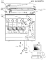
図1に、本発明の一実施例の複合機能フルカラーデジタル複写機MF1の機構概要を示す。このフルカラー複写機は、大略で、自動原稿送り装置(ADF)200と、操作ボード10と、カラースキャナ300と、カラープリンタ100の各ユニットで構成されている。機内のシステムコントローラ501(図5)には、パソコンPCが接続したLAN(Local Area Network)が接続されている。また、機内のファクシミリコントローラFCU(図5)は、交換機PBXおよび公衆通信網PNを介して、ファクシミリ通信をすることが出来る。
FIG. 1 shows an outline of the mechanism of a multi-function full-color digital copying machine MF1 according to an embodiment of the present invention. This full-color copying machine is roughly constituted by units of an automatic document feeder (ADF) 200, an
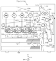
図2に、複合機能複写機MF1のカラープリンタ100の機構を示す。この実施例のカラープリンタ100は、レーザプリンタである。このレーザプリンタ100は、黒(ブラック:Bk),シアン(C),マゼンダ(M)およびイエロー(Y)の各色の画像を形成するための4組のトナー像形成ユニットBk,C,MおよびYが、第1転写ベルト107の移動方向(図中の左から右方向y)に沿ってこの順に配置されている。即ち、4連ドラム方式のフルカラー画像形成装置である。これらのトナー像形成ユニットBk,C,MおよびYはそれぞれ個別の、プリンタ本体に対して着脱可能なプロセスカートリッジである。
FIG. 2 shows the mechanism of the
プロセス動作位置に装着された各カートリッジを引き出し(取り外し)不可に拘束するための各ロック機構がある。各ロック機構は、拘止爪があるロックレバーおよび該ロックレバーを拘止位置と解除位置に駆動する電気モータ(156:イエローカートリッジ用)で構成され、各カートリッジには、ロックレバーの拘止爪が係合するロック穴がある。各カートリッジの現像器(103:イエロー現像用)にトナーボトル(128:イエロートナー)のトナーを補充する間はカートリッジの取り出し(引き出し)ができないように、ロック機構によってカートリッジがロックされる。 There are lock mechanisms for restraining each cartridge mounted at the process operation position from being pulled out (removable). Each lock mechanism includes a lock lever with a detent pawl and an electric motor (156: for yellow cartridge) that drives the lock lever to a detent position and a release position. Each cartridge has a detent pawl for the lock lever. There is a lock hole to engage. The cartridge is locked by the locking mechanism so that the cartridge cannot be taken out (drawn) while the toner bottle (128: yellow toner) is replenished to the developing device (103: yellow developing) of each cartridge.
イエロートナー像形成ユニットYの、回転可能に支持され矢印方向に回転する感光体101の外周部には、除電装置105,クリーニング装置104,帯電装置102および現像器103が配備されている。帯電装置102と現像器103の間には、露光装置106から発せられる光情報の入るスペースが確保されている。トナー像形成ユニットは4組(Bk,C,M,Y)あるが、それぞれ周囲に設けられる画像形成用の部品構成は同じである。現像器103が扱う色材(トナー)の色が異なる。感光体101(4個)は直径が30から100mm程度のアルミニュム円筒表面に、光導電性物質である有機半導体の層を設けた感光体である。その一部が、第1転写ベルト107に接している。ベルト状の感光体も採用可能である。
A neutralizing
第1転写ベルト107は矢印方向に移動可能に、回転するローラ108,109および110間に支持、張架されていて、裏側(ループの内側)には、第1転写手段111が感光体101の近傍に配備されている。ベルトループの外側に、第1転写ベルト用のクリーニング装置112が配備されている。第1転写ベルト107より転写した後にその表面に残留する不要のトナーを拭い去る。
The
露光装置106は公知のレーザ方式で、フルカラー画像形成に対応した光情報を、一様に帯電された感光体表面に潜像として照射する。LEDアレイと結像手段から成る露光装置も採用できる。第1転写ベルト107は、基体の厚みが50μm乃至600μmの樹脂フィルムあるいはゴムを基体にしたベルトで、感光体101からトナーを転写可能とする抵抗値を備える。
The
図2上で、第1転写ベルト107の右方には、第2転写ベルト113が配備されている。第2転写ベルト113は矢印方向に移動可能に、回転ローラ114,115および116間に支持、張架されていて、裏側(ループの内側)には、第2転写手段117が配備されている。ベルトループの外側に、第2転写ベルト用のクリーニング装置118、チャージャ119、などが配備されている。クリーニング装置118は、用紙にトナーを転写した後、残留する不要のトナーを拭い去る。
In FIG. 2, a
第2転写手段117,ローラ116、第1転写ベルト107を支持するローラ108により、第1転写ベルト107と第2転写ベルト113は接触し、あらかじめ定められた転写ニップを形成する。第2転写ベルト113は、基体の厚みが50μm乃至600μmの樹脂フィルムあるいはゴムを基体にしたベルトで、第1転写ベルト107からトナーを転写可能とする抵抗値を備えるベルトである。
The
記録媒体である用紙120は、図の下方の給紙カセット121,122に収納されており、最上の用紙が給紙ローラ131又は132で1枚づつ、複数の用紙ガイドを経てレジストローラ133に搬送される。第2転写ベルト113の上方に、定着器123、排紙ガイド124、排紙ローラ125、排紙スタック126が配備されている。
第1転写ベルト107の上方で、排紙スタック126の下方には、トナーボトル128を着脱(交換)できる補給基枠127がある。ブラック,シアン,マゼンタおよびイエローの4色それぞれのトナーを収納した、各色トナーボトル(128:イエロー)が補給基枠127のボトル装着口に挿入されている。各ボトルのトナーが、各現像装置(103:イエロー)に適宜補給される。
Above the
本体の一部のフレーム129は、開閉支軸130を中心として、回動開放が可能な構造にしてあるので、記録媒体の搬送路は大きく開き、ジャムした記録媒体(用紙)の処理を容易にしている。
The
ここで両面印刷のときの各部の動作を説明する。まず感光体101による、作像が行われる。すなわち、露光装置106の作動により、不図示のLD光源からの光は、不図示の光学部品を経て、帯電装置102で一様に帯電された感光体101のうち、作像ユニットaの感光体上に至り、書き込み情報(色に応じた情報)に対応した潜像を形成する。感光体101上の潜像は現像器103で現像され、トナーによる顕像が感光体101の表面に形成され保持される。このトナー像は、第1転写手段111により、感光体101と同期して移動する第1転写ベルト107の表面に転写される。感光体101の表面は、残存するトナーがクリーニング装置104でクリーニングされ、除電装置105で除電され次の作像サイクルに備える。
Here, the operation of each unit during duplex printing will be described. First, image formation is performed by the
第1転写ベルト107は、表面に転写されたトナー像を坦持し、矢印の方向に移動する。作像ユニットbの感光体101に、別の色に対応する潜像が書き込まれ、対応する色のトナーで現像され顕像となる。この像は、すでに第1転写ベルト107に乗っている前の色の顕像に重ねられ、最終的に4色重ねられる。なお、単色黒のみを形成する場合もある。
The
このとき同期して第2転写ベルト113は矢印方向に移動していて、第2転写手段117の作用で、第2転写ベルト113の表面に第1転写ベルト107表面に作られた画像が転写される。いわゆるタンデム形式である4個の作像ユニットa〜dの各感光体101上で画像が形成されながら、第1,第2転写ベルト107,113が移動し、作像が進められるので、その時間が短縮できる。
At this time, the
第1転写ベルト107が、所定のところまで移動すると、用紙の別の面に作成されるべきトナー画像が、前述したような工程で再度感光体101により作像され、給紙が開始される。給紙ローラ131又は132が反時計方向に回転すると、給紙カセット121又は122内の最上部にある用紙120が引き出され、レジストローラ133に搬送される。
When the
レジストローラ133を経て、第1転写ベルト107と第2転写ベルト113の間に送られる用紙の片側の面に、第1転写ベルト107表面のトナー像が、第2転写手段117により転写される。更に記録媒体は上方に搬送され、第2転写ベルト113表面のトナー像が、チャージャ119により用紙のもう一方の面に転写される。転写に際して、用紙は画像の位置が正規のものとなるよう、タイミングがとられて搬送される。
The toner image on the surface of the
本実施例では、感光体101に作像されるトナーの極性はマイナスである。第1転写手段111にプラスの電荷を与えることで、感光体101に作像されたトナーは第1転写ベルト107に転写される。第2転写手段117にプラスの電荷を与えることで、第1転写ベルト107に転写されたトナーは、第2転写ベルト113に転写される。用紙を第1,第2転写ベルト107,113間に送り込み、第2転写手段117にプラスの電荷を与えることで、第1転写ベルト107に転写されたトナーが用紙の片側の面に転写され、また、第2転写ベルト113に転写されたトナーは、転写チャージャ119からプラス極性の電荷与えることで、第2転写ベルト113表面のマイナス極性のトナーは吸引されて、用紙の他の面に転写される。
In this embodiment, the polarity of the toner imaged on the
上記のステップで両面にトナー像が転写された用紙は、定着器123に送られ、用紙上のトナー像(両面)が一度に溶融、定着され、ガイド124を経て排紙ローラ125により本体フレーム上部の排紙スタック126に排出される。
The paper on which the toner images are transferred on both sides in the above steps is sent to the
図2のように、排紙部124〜126を構成した場合、両面画像のうち後から用紙に転写される面(頁)、すなわち第1転写ベルト7から用紙に直接転写される面が下面となって、排紙スタック126に載置されるから、頁揃えをしておくには2頁目の画像を先に作成し、第2転写ベルト113にそのトナー像を保持し、1頁目の画像を第1転写ベルト107から用紙に直接転写する。
As shown in FIG. 2, when the
第1転写ベルト107から直接に用紙に転写される画像は、感光体表面で正像にし、第2転写ベルト113から用紙に転写されるトナー像は、感光体表面で逆像(鏡像)になるよう露光される。このような頁揃えのための作像順、ならびに、正、逆像(鏡像)に切り換える画像処理も、IMACによるメモリMEMに対する画像データの読書き制御によって行っている。
The image directly transferred from the
第2転写ベルト113から用紙に転写した後、ブラシローラ,回収ローラ,ブレード等を備えたクリーニング装置118が、第2転写ベルト113に残留する不要のトナーや紙粉を除去する。
After the transfer from the
図2ではクリーニング装置118のブラシローラが第2転写ベルト113の表面から離れた状態にある。支点118aを中心として揺動可能で、第2転写ベルト113の表面に接離可能な構造になっている。用紙に転写する以前で、第2転写ベルト113がトナー像を担持しているとき離し、クリーニングが必要のとき、図で反時計方向に揺動し接触させる。除去された不要トナーはトナー収納部134に集められる。
In FIG. 2, the brush roller of the cleaning device 118 is away from the surface of the
以上が、「両面転写モード」を設定した両面印刷モードの作像プロセスである。両面印刷の場合には、常にこの作像プロセスで印刷が行われる。片面印刷の場合には、「第2転写ベルト113による片面転写モード」と「第1転写ベルト107による片面転写モード」の2つがあり、前者の第2転写ベルト113を用いる片面転写モードを設定した場合には、第1転写ベルト107に4色重ね(又は単色黒)で形成された顕像が第2転写ベルト113に転写され、そして用紙の片面に転写される。用紙の他面には画像転写はない。この場合、排紙スタック126に排出された印刷済用紙の上面に印刷画面がある。
The image forming process in the duplex printing mode in which the “duplex transfer mode” is set has been described above. In the case of duplex printing, printing is always performed by this image forming process. In the case of single-sided printing, there are two types of “single-sided transfer mode by the
後者の第1転写ベルト107を用いる片面転写モードを設定した場合には、第1転写ベルト107に4色重ね(又は単色黒)で形成された顕像が、第2転写ベルト113には転写されずに、用紙の片面に転写される。用紙の他面には画像転写はない。この場合は、排紙スタック126に排出された印刷済用紙の下面に印刷画面がある。
When the single-side transfer mode using the latter
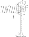
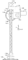
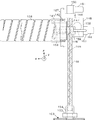
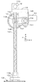
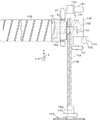
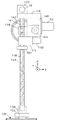
図3および図4に、図2に示す補給基枠127に装備した、イエロートナーボトル128からイエロー現像器103にトナーを補給するイエロートナー補給機構を示す。他の、ブラック,シアンおよびマゼンタトナーボトルのそれぞれから、ブラック,シアンおよびマゼンタ現像器にトナーを補給する各色トナー補給機構の構成および機能も、イエロートナー補給機構と同一である。図3はトナーボトル128の側面を見た拡大図である。図4は図2の紙面の裏側から表側を見た拡大図であって、図3に示すトナー補給機構の右側面図である。
3 and 4 show a yellow toner replenishment mechanism equipped in the
トナーボトル128は、側壁面にトナー送り出し用の螺旋溝が形成されておりこれが、トナー内部では螺旋突条となっている。この螺旋溝は、トナー出口近くの小径部にも連続しており、該小径部がトナー出口に連なる箇所で出口壁面と同径になるようにねじって絞った形状になっている。この形状により、図3に示す水平姿勢でトナーボトル128をその中心軸を中心に廻すと、内部のトナーが螺旋突条によってボトルの出口に向けて押され、出口近くのトナーから出て行く。トナーボトル128の外壁には、リング状の歯車141の内壁面の溝に係合する突起が形成されている。
The
補給基枠127には、ベアリング142で回転自在に支持された外段差つきのリング状の歯車141がある。その係合溝にボトルの突起を嵌め合わせてトナーボトル128を歯車141の内空間に差し込むと、トナーボトル128のトナー出口(ボトル口部)が、歯車141の中心位置に固定配置された受け口部材146の、水平x方向に延びる受け穴に嵌まり込む。リング状の歯車141には駆動ギア153が噛み合っており、この駆動ギア153は減速機145の出力軸に結合している。減速機145の入力軸には、電気モータ152(補給モータ)の入力軸が連結されている。電気モータ152が回転すると、リング状の歯車141が回転し、この歯車141に係合したトナーボトル128が、その中心軸を中心に回転し、ボトル128内のトナーが、受け口部材146の受け穴に出て行く。前記減速機145のフレームは、補給基枠127に固定された機構ベース144に固定されている。受け口部材146は、減速機145のフレームで固定支持されている。
The
受け口部材146の、ボトル128の口部が嵌まり込む、水平x方向に延びる受け穴は深く、該受け穴を垂直z方向に貫通するパイプ穴が開いており、そこにスクリューコンベアのパイプ147および148(トナー搬送路)の下端および上端が嵌まり込んでいる。パイプ147および148を、トナー搬送用のスクリュー149が貫通している。スクリュー149の軸端は、機構ベース144に装着した減速器150の出力軸に連結されている。減速器150の入力軸には電気モータ151(搬送モータ)の回転軸が連結されている。電気モータ151が回転すると、スクリュー149が回転して、ボトル128から受け口部材146内の受け穴に出たトナーを、パイプ148に掻き込んで下方に搬送する。
A receiving hole extending in the horizontal x direction into which the mouth portion of the
パイプ148の下端には、小距離を上下摺動し得る、透光性のセンサブロック154が装着されており、該ブロック154に、該ブロック154の内部残留トナーを検出するトナーセンサ155が装着されている。センサ155は、この実施例では、透過型の光センサである。センサブロック154の下端面は、現像器103のトナー補充口に少し嵌まり込む形状となっている。センサブロック154は、パイプ148に対して上下z方向に摺動できるので、現像器103の脱着のときには、現像器103の移動にともなって現像器103のトナー補充口から外れて上方に移動し、あるいは下方に移動してトナー補充口に僅かに嵌まり込む。
A light-transmitting
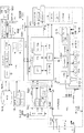
図5に、図1に示す複合機能複写機MF1の電装系統のシステム構成を示す。電装システムは、画像形成装置の全体制御を行うシステムコントローラ501、コントローラ501に接続された、画像形成装置の操作ボード10、画像データを記憶するHDD503、アナログ回線を使用して外部との通信を行う通信コントロール装置インターフェースボード504、LANインターフェースボード505、汎用PICバスに接続された、FAXのコントロールユニット506、IEEE1394ボード、無線LANボード、USBボード等507と、PCIバスでコントローラに接続されたエンジン制御510、エンジン制御510に接続された、画像形成装置のI/Oを制御するI/Oボード513、及び、コピー原稿(画像)を読込むスキャナーボード(SBU:Sensor Board Unit)511、及び画像データが表わす画像光を感光体ドラム上に投射する(光書込みする)LDB(レーザダイオードボード)512等で構成される。
FIG. 5 shows a system configuration of the electrical system of the multifunction copying machine MF1 shown in FIG. The electrical system communicates with the outside using a
原稿を光学的に読み取る読取ユニット300は、原稿に対する原稿照明光源の走査を行い、CCD520に原稿像を結像する。原稿像すなわち原稿に対する光照射の反射光をCCD520で光電変換してR,G,B画像信号を生成する。
A
通信コントロール装置インターフェイスボード504は、装置に不具合が発生した場合に外部の遠隔地診断装置に即時に通報し、故障個所の内容,状況等をサービスマンが認識し早急に修理することを可能としている。また、それ以外に装置の使用状況等の発信にも使用されている。 The communication control device interface board 504 immediately notifies an external remote diagnosis device when a failure occurs in the device, and allows a serviceman to recognize the content and situation of the failure part and repair it immediately. . In addition, it is also used for sending out the usage status of the device.
図5に示すCCD520は、3ラインカラーCCDであり、EVENch(偶数画素チャンネル)/ODDch(奇数画素チャンネル)のR、G、B画像信号を生成し、SBUボードのアナログASIC(Application Specific IC)に入力する。SBUボード511にはアナログASIC及び,CCD、アナログASICの駆動タイミングを発生する回路を備えている。CCD520の出力は、アナログASIC内部のサンプルホールド回路により、サンプルホールドされその後、A/D変換され、R、G、Bの画像データに変換し、且つシェーディング補正し、そして出力I/F(インターフェイス)520で画像データバスを介して画像データ処理器IPP(Image Processing Processor;以下では単にIPPと記述)に送出する。
The
IPPは画像処理をおこなうプログラマブルな演算処理手段であり、分離生成(画像が文字領域か写真領域かの判定:像域分離),地肌除去,スキャナガンマ変換,フィルタ,色補正,変倍,画像加工,プリンタガンマ変換および階調処理を行う。SBUからIPPに転送された画像データは、IPPにて光学系およびデジタル信号への量子化に伴う信号劣化(スキャナ系の信号劣化)を補正され、フレームメモリ521に書き込まれる。
IPP is a programmable arithmetic processing means that performs image processing, separation generation (determination of whether an image is a character area or a photographic area: image area separation), background removal, scanner gamma conversion, filter, color correction, scaling, and image processing. , Perform printer gamma conversion and gradation processing. The image data transferred from the SBU to the IPP is corrected by the IPP for signal deterioration due to quantization of the optical system and the digital signal (signal deterioration of the scanner system) and written in the
システムコントローラ501には、CPU及びシステムコントローラボードの制御を行うROM、CPUが使用する作業用メモリであるRAM,リチウム電池を内臓し、SRAMのバックアップと時計を内臓したNV−RAM及び、システムコントローラボードのシステバス制御、フレームメモリ制御、FIFO等のCPU周辺を制御するASIC及びそのインターフェース回路等が搭載されている。
The
システムコントローラ501は、スキャナアプリケーション,ファクシミリアプリケーション,プリンタアプリケーションおよびコピーアプリケーション等の複数アプリケーションの機能を有し、システム全体の制御を行う。操作ボード10の入力を解読して本システムの設定とその状態内容を操作ボードの表示部に表示する。
A
PCIバスには多くのユニットが接続されており、画像データバス/制御コマンドバスで、画像データと制御コマンドが時分割で転送される。 Many units are connected to the PCI bus, and image data and control commands are transferred in a time-sharing manner by the image data bus / control command bus.
通信コントロール装置インターフェースボード504は、通信コントロール装置と、コントローラ501との通信インターフェースボードである。コントローラ501との通信は、全二重非同期シリアル通信で接続されている。通信コントロール装置522とは、RS−485インターフェース規格により、マルチドロップ接続されている。遠隔の管理システムとの通信は、この通信コントローラ装置インターフェースボード504を経由して実施される。
The communication control device interface board 504 is a communication interface board between the communication control device and the
LANインターフェースボード505は、社内LANに接続されている。社内LANとコントローラ501との通信インターフェースボードであり、PHYチップを搭載している。LANインターフェースボード505とコントローラ501とは、PHYチップI/F及びI2CバスI/Fの標準的な通信インターフェースで接続されている。外部機器との通信はこのLANインターフェースボード505を経由して実施される。
The
HDD503は、システムのアプリケーションプログラムならびにプリンタ、作像プロセス機器の機器付勢情報を格納するアプリケーションデータベース、ならびに、読取り画像や書込み画像のイメージデータ、すなわち画像データ、ならびにドキュメントデータを蓄える画像データベースとして用いられる。物理インターフェース、電気的インターフェース共に、ATA/ATAPI−4に準拠したインターフェースでコントローラに接続されている。
The
操作ボード10には、CPU及びROM,RAM、LCD及びキー入力を制御するASIC(LCDC)が搭載されている。ROMには操作ボード10の入力読込み、及び表示出力を制御する、操作ボード10の制御プログラムが書き込まれている。RAMは、CPUで使用する作業用メモリである。システムコントローラ501との通信により、パネルを操作して使用者がシステム設定の入力を行う入力と、使用者にシステムの設定内容,状態を表示する、表示および入力の制御を行っている。
The
システムコントローラ501のワークメモリから出力されたブラック(Bk)、シアン(C)、マデンタ(M)、イエロー(Y)の各色の書き込み信号は、LDB(Laser Diode control Board)のBk,C,M,YのLD(Laser Diode)書き込み回路に入力される。LD書き込み回路でLD電流制御(変調制御)が行われ、各LDに出力される。
The black (Bk), cyan (C), magenta (M), and yellow (Y) write signals output from the work memory of the
エンジン制御510は、画像形成の作像作成制御を主として行い、CPU517及び、画像処理を行うIPP、複写およびプリントアウトを制御するため必要なプログラムを内蔵したROM、その制御に必要なRAM、及びNV−RAMを搭載している。NV−RAMにはSRAMと、電源OFFを検知して、EEPROMにストアするメモリを搭載している。また、他の制御を行なうCPUとの信号の送受信を行なう、シリアルインターフェースも備えているI/O ASICは、エンジン制御ボードが実装された、近くのI/O(カウンター、ファン、ソレノイド、モータ等)を制御するASICである。I/O制御ボード513とエンジン制御ボード510とは同期シリアルインターフェース接続されている。
The
I/O制御ボード513には、サブCPUを搭載しており、Pセンサ、Tセンサ等のアナログ制御,用紙センサの検出信号を参照するジャム検出,用紙搬送制御も含む画像形成装置のI/O制御を行っている。インターフェース回路515は、各種センサ,アクチュエータ(モータ、クラッチ、ソレノイド)とのインターフェース回路である。
The I /
電源装置PSU514は、画像形成装置を制御する電源を供給するユニットである。メインSWのオン(閉)により、商用電源が供給される。その商用電源からAC制御回路540に商用ACが供給され、AC制御回路540により整流、平滑化のように制御されたAC制御出力を用いて、第1電源装置PSU(1) 514は各制御基板に必要なDC電圧を供給する。電源装置PSUにより生成される定電圧を用いて各制御部のCPUが動作している。
The power
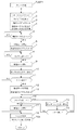
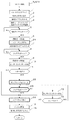
図6に、エンジン制御510のCPU517が実行するトナー補給制御の中の、Y(イエロー)トナー補給制御TySP1の内容を示す。このYトナー補給制御TySP1は、YプロセスカートリッジのY現像器103のトナー濃度が設定値以下に低下したときに実行するものである。同様に、他の、Bk,CおよびMプロセスカートリッジのBk,CおよびM現像器のトナー濃度が設定値以下に低下したときにも、それぞれBk,CおよびMトナー補給制御を行うが、これらの内容も、図6に示し次に説明するYトナー補給制御TySP1の内容と同様である。
FIG. 6 shows the contents of the Y (yellow) toner supply control TySP1 in the toner supply control executed by the
Yトナー補給制御TySP1に進むと、エンジン制御510のCPU517は、Yプロセスカートリッジをロックする(ステップ1)。すなわち、ロック機構の電気モータ156(図2)を正転駆動して、ロックレバーの拘止爪をYプロセスカートリッジのロック穴に嵌め込む。なお、以下においては、括弧内には、ステップという語を省略して、ステップNo.数字のみを記す。
When the process proceeds to the Y toner supply control TySP1, the
そしてCPU517は、操作ボード10のディスプレイに「プロセスカートリッジ引き出し不可」を表示し(2)、Ts時限の補給タイマTsをスタートして(3)、トナー補給モータ152およびトナー搬送モータ151の正転駆動を開始する(4)。そして補給タイマTsのタイムオーバ(Tsの経過)を待つ(5)。トナー補給モータ152の正転により、トナーボトル128がその中心軸を中心に回転し、これによりボトル128内のトナーが、受け口部材146のトナー受け穴に送り出される。トナー搬送モータ151の正転により、コンベアスクリュー149が回転して、トナー受け穴に送り出されたトナーを、YプロセスカートリッジのY現像器103に搬送する。
Then, the
補給タイマTsがタイムオーバするとCPU517は、補給モータ152の回転を止めて(6)、Tc時限の搬送継続タイマTcをスタートして(7)、搬送モータ151の回転は継続する。これにより、トナーボトル128の回転が停止してボトル128からのトナーの送給は停止するが、コンベアスクリューが回転を継続するので、パイプ148内にあるトナーの、現像器103への搬送が継続する。Tc時限は、受け口部材146のトナーを現像器103に搬送するに必要な時間に更に余裕代を加えた、パイプ148のトナーを現像器103に送り込むに十分な時間である。
When the replenishment timer Ts expires, the
搬送継続タイマTcがタイムオーバするとCPU517は、搬送モータ151の回転を止めて(8,9)、センサ155がトナーを検出しているか判定して(10)、トナーを検出していないと、ロックを解除する(11,18)。すなわちロック機構の電気モータ156を逆転駆動して拘止爪をYプロセスカートリッジのロック穴から外す。これによりYプロセスカートリッジの取り出しが可能になる。そして、操作ボード10の「プロセスカートリッジ引き出し不可」表示を消去する(18a)。
When the conveyance continuation timer Tc expires, the
ステップ10でセンサ155がトナーを検出していたときは、搬送モータ151を再度回転駆動し(12)、搬送継続タイマTcを再スタートして(13)、センサ155がトナーを検出しているか監視して(15)、センサ155がトナーを検出しなくなると、搬送モータ151を止めて(16,17)、Yプロセスカートリッジのロックを解除して(18)、操作ボード10の「プロセスカートリッジ引き出し不可」表示を消去する(18a)。
If the
センサ155がトナーを検出している間に搬送継続タイマTcがタイムオーバすると、そこで搬送モータ151を止めて(16,17)、Yプロセスカートリッジのロックを解除して(18)、操作ボード10の「プロセスカートリッジ引き出し不可」表示を消去する(18a)。
When the transport continuation timer Tc expires while the
第2実施例のハードウエアおよび機能は、図1〜図6に示した上述の第1実施例のものと、大部分が同じであるが、トナー補給機構およびトナー補給制御に少々の変更がある。図7および図8に、第2実施例のトナー補給機構を示す。このトナー補給機構は、第1実施例のトナー補給機構に、電気モータ158(ポンプモータ)で駆動するエアーポンプ157を付加してその吐出エアーを、受け口部材146のトナー受け穴に送給する。他のハードウエアは上述の第1実施例と同様である。
The hardware and functions of the second embodiment are mostly the same as those of the first embodiment shown in FIGS. 1 to 6, but there are some changes in the toner supply mechanism and toner supply control. . 7 and 8 show the toner supply mechanism of the second embodiment. This toner replenishing mechanism adds an
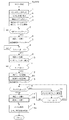
図9に、第2実施例のCPU517のYトナー補給制御TySP2を示す。第2実施例では、ボトル128からトナーを送り出すための補給モータ152を停止すると(6)、搬送モータ151の駆動は継続してポンプモータ158の駆動を開始する(21)。そして時限Tcが経過すると搬送モータ151を停止し(9)、ポンプモータ158の駆動は継続して、センサ155がトナーを検出しているか判定して(10)、トナーを検出していたときは、Tp時限のポンプタイマTpをスタートして(22)、センサ155がトナーを検出しているか監視して(15)、センサ155がトナーを検出しなくなると、ポンプモータ158を止めて(16,24)、Yプロセスカートリッジのロックを解除して(18)、操作ボード10の「プロセスカートリッジ引き出し不可」表示を消去する(18a)。
FIG. 9 shows the Y toner supply control TySP2 of the
センサ155がトナーを検出している間にポンプタイマTpがタイムオーバすると、そこでポンプモータ158を止めて(23,24)、Yプロセスカートリッジのロックを解除して(18)、操作ボード10の「プロセスカートリッジ引き出し不可」表示を消去する(18a)。その他の機能は、第1実施例と同様である。
When the pump timer Tp expires while the
第3実施例のハードウエアおよび機能も、図1〜図6に示した上述の第1実施例のものと、大部分が同じであるが、トナー補給機構およびトナー補給制御に少々の変更がある。図10および図11に、第3実施例のトナー補給機構を示す。このトナー補給機構は、第1実施例のトナー補給機構に、加振器を付加したものである。本実施例の加振器は、減速機160,その出力軸に結合した加振用の偏心ローラ161および減速機160の入力軸に連結した電気モータ(振動モータ)で構成される。偏心ローラ161は、楕円形状であり、その回転により、パイプ148に間断接触することでパイプ148を振動させる。他のハードウエアは上述の第1実施例と同様である。
The hardware and functions of the third embodiment are also largely the same as those of the first embodiment shown in FIGS. 1 to 6, but there are some changes in the toner supply mechanism and toner supply control. . 10 and 11 show the toner supply mechanism of the third embodiment. This toner supply mechanism is obtained by adding a vibrator to the toner supply mechanism of the first embodiment. The vibration exciter of the present embodiment includes a
図12に、第3実施例のCPU517のYトナー補給制御TySP3を示す。第3実施例では、搬送継続タイマTcのタイムオーバを待って搬送モータ151を止めて(9)、センサ155がトナーを検出しているか判定して(10)、トナーを検出していたときは、搬送モータ151を再度駆動し(12)、振動モータ162の駆動を開始し(31)、搬送継続タイマTcを再スタートする(13)。センサ155がトナーを検出しているか監視して(15)、センサ155がトナーを検出しなくなると、搬送モータ151を止めて(16,17)、振動モータ162も止めて(32)、Yプロセスカートリッジのロックを解除して(18)、操作ボード10の「プロセスカートリッジ引き出し不可」表示を消去する(18a)。
FIG. 12 shows the Y toner supply control TySP3 of the
センサ155がトナーを検出している間に搬送継続タイマTcがタイムオーバすると、そこで搬送モータ151を止めて(16,17)、振動モータ162も止めて(32)、Yプロセスカートリッジのロックを解除して(18)、操作ボード10の「プロセスカートリッジ引き出し不可」表示を消去する(18a)。その他の機能は、第1実施例と同様である。
When the conveyance continuation timer Tc expires while the
−その他−
パイプ148が垂直姿勢であるので、第1実施例の、コンベアスクリュー149,減速機150および電気モータ151を、第2実施例のエアー搬送機構に変更した態様でも本発明を実施することができる。また、第1実施例の、コンベアスクリュー149,減速機150および電気モータ151を、第3実施例の加振搬送機構に変更した態様でも本発明を実施することができる。さらには、第1実施例の、コンベアスクリュー149,減速機150および電気モータ151を、第2実施例のエアー搬送機構と第3実施例の加振搬送機構の組み合わせに変更した態様でも本発明を実施することができる。また、第2実施例に、第3実施例の加振搬送機構を組み込んだ態様でも良い。
-Others-
Since the
10:操作ボード
100:カラープリンタ
101:感光体
102:帯電ローラ
103:現像器
104:クリーナ
105:除電ランプ
106:光書込みユニット
108,111,117:転写ローラ
107,113:転写ベルト
121,122:給紙トレイ
123:定着ユニット
126:排紙スタック
127:補給基枠
128:トナーボトル
133:レジストローラ
141:リング状の歯車
142:ベアリング
144:機構ベース
145:減速機
146:受け口部材146
147:パイプ
148:トナー搬送パイプ
149:コンベアスクリュー
150:減速機
151:電気モータ(搬送モータ)
152:電気モータ(補給モータ)
153:駆動ギア
154:透光性のセンサブロック
155:トナーセンサ
156:ロック機構の電気モータ
157:エアーポンプ
158:電気モータ(ポンプモータ)
159:送気チューブ
160:減速機
161:偏心ローラ
162:電気モータ(加振モータ)
200:自動原稿供給装置
300:カラー原稿スキャナ
PC:パソコン
PBX:交換器
PN:通信回線
SBU:センサ・ボードユニット
IPP:画像データ処理器
10: Operation board 100: Color printer 101: Photoconductor 102: Charge roller 103: Developer 104: Cleaner 105: Static elimination lamp 106:
147: Pipe 148: Toner conveying pipe 149: Conveyor screw 150: Reducer 151: Electric motor (conveying motor)
152: Electric motor (supply motor)
153: drive gear 154: translucent sensor block 155: toner sensor 156:
159: Air supply tube 160: Reducer 161: Eccentric roller 162: Electric motor (vibration motor)
200: automatic document feeder 300: color document scanner PC: personal computer PBX: exchange PN: communication line SBU: sensor board unit IPP: image data processor
Claims (9)
トナー収納容器;
該トナー収納容器から出たトナーを前記現像器に導くトナー搬送路;
該トナー搬送路のトナーを前記現像器に送給する搬送手段;および、
前記トナー収納容器からトナーをトナー搬送路に送出して現像器に供給するトナー供給後、トナー収納容器からのトナーの送出は停止して前記トナー搬送路の残留トナーを排除するために前記搬送手段を駆動する搬送制御手段;
を備えることを特徴とする、画像形成装置。 An electrophotographic process in which image light is projected onto a photosensitive member to form an electrostatic latent image, the electrostatic latent image is developed into a toner image by a developing device, and the toner image is transferred directly or indirectly to a sheet via an intermediate transfer member. In an image forming apparatus that performs image formation of
Toner storage container;
A toner transport path for guiding the toner from the toner storage container to the developer;
Conveying means for feeding toner in the toner conveying path to the developing device; and
After the toner is supplied from the toner container to the toner conveying path and supplied to the developing device, the conveying means is used to stop the toner from the toner container and to remove the residual toner in the toner conveying path. Transport control means for driving
An image forming apparatus comprising:
原稿の画像を読み取り画像データを生成する画像読取装置;を備え、
前記画像形成装置は、該画像読取装置が生成した画像データを、画像形成に適合する画像データに変換する画像データ処理手段を含む;
複写装置。
The image forming apparatus according to claim 1; and
An image reading device that reads an image of a document and generates image data;
The image forming apparatus includes image data processing means for converting image data generated by the image reading apparatus into image data suitable for image formation;
Copy machine.
Priority Applications (1)
| Application Number | Priority Date | Filing Date | Title |
|---|---|---|---|
| JP2005142418A JP2006317841A (en) | 2005-05-16 | 2005-05-16 | Image forming apparatus and copying apparatus |
Applications Claiming Priority (1)
| Application Number | Priority Date | Filing Date | Title |
|---|---|---|---|
| JP2005142418A JP2006317841A (en) | 2005-05-16 | 2005-05-16 | Image forming apparatus and copying apparatus |
Publications (1)
| Publication Number | Publication Date |
|---|---|
| JP2006317841A true JP2006317841A (en) | 2006-11-24 |
Family
ID=37538553
Family Applications (1)
| Application Number | Title | Priority Date | Filing Date |
|---|---|---|---|
| JP2005142418A Pending JP2006317841A (en) | 2005-05-16 | 2005-05-16 | Image forming apparatus and copying apparatus |
Country Status (1)
| Country | Link |
|---|---|
| JP (1) | JP2006317841A (en) |
Cited By (2)
| Publication number | Priority date | Publication date | Assignee | Title |
|---|---|---|---|---|
| JP2011008142A (en) * | 2009-06-29 | 2011-01-13 | Canon Inc | Image forming apparatus and method thereof |
| JP2012047985A (en) * | 2010-08-26 | 2012-03-08 | Kyocera Mita Corp | Image forming apparatus |
-
2005
- 2005-05-16 JP JP2005142418A patent/JP2006317841A/en active Pending
Cited By (3)
| Publication number | Priority date | Publication date | Assignee | Title |
|---|---|---|---|---|
| JP2011008142A (en) * | 2009-06-29 | 2011-01-13 | Canon Inc | Image forming apparatus and method thereof |
| JP2012047985A (en) * | 2010-08-26 | 2012-03-08 | Kyocera Mita Corp | Image forming apparatus |
| US8611789B2 (en) | 2010-08-26 | 2013-12-17 | Kyocera Document Solutions, Inc. | Image forming apparatus including demountable developing unit |
Similar Documents
| Publication | Publication Date | Title |
|---|---|---|
| JP5267012B2 (en) | Waste toner collecting container, cleaning unit, and image forming apparatus | |
| US7817934B2 (en) | Image forming apparatus with power saving sleep mode | |
| JP5262470B2 (en) | Method and apparatus for detecting and repairing connection abnormality of process cartridge and image forming apparatus | |
| JP3501964B2 (en) | Image output processing device | |
| JP5181490B2 (en) | Developing device and image forming apparatus | |
| US7853179B2 (en) | Method and apparatus for regulating toner amount in developing chamber of image forming apparatus | |
| JP4250918B2 (en) | Image forming apparatus and method | |
| JP4955963B2 (en) | Image forming apparatus | |
| JP4176698B2 (en) | Waste developer recovery device and image forming apparatus having the same | |
| JP2006317841A (en) | Image forming apparatus and copying apparatus | |
| JP2012053085A (en) | Image forming apparatus | |
| JP3700473B2 (en) | Toner cartridge replacement detection device and image forming apparatus using the same | |
| JP5066396B2 (en) | PRINT PROCESSING DEVICE, MULTIFUNCTION IMAGE FORMING DEVICE, AND SINGLE FUNCTION IMAGE FORMING DEVICE | |
| JP2012133095A (en) | Image forming system | |
| JP2008203511A (en) | Image forming apparatus | |
| JP4211302B2 (en) | Image forming apparatus | |
| JP5755112B2 (en) | Image forming apparatus | |
| JP5097605B2 (en) | Image forming apparatus and waste developer collecting apparatus | |
| JP5173169B2 (en) | Image forming apparatus | |
| JP2009048112A (en) | Method for controlling conveyance of waste toner for image forming apparatus and image forming apparatus | |
| JP2007193189A (en) | Image forming apparatus | |
| JP2007235852A (en) | Image reading device | |
| JP2005164728A (en) | Image forming apparatus | |
| JP2016133785A (en) | Toner supply device and image forming apparatus | |
| JP2010230908A (en) | Image forming apparatus |