JP2006304473A - Vehicle component drive control circuit and manufacturing method therefor - Google Patents
Vehicle component drive control circuit and manufacturing method therefor Download PDFInfo
- Publication number
- JP2006304473A JP2006304473A JP2005121983A JP2005121983A JP2006304473A JP 2006304473 A JP2006304473 A JP 2006304473A JP 2005121983 A JP2005121983 A JP 2005121983A JP 2005121983 A JP2005121983 A JP 2005121983A JP 2006304473 A JP2006304473 A JP 2006304473A
- Authority
- JP
- Japan
- Prior art keywords
- vehicle
- storage memory
- vehicle component
- frequency
- control circuit
- Prior art date
- Legal status (The legal status is an assumption and is not a legal conclusion. Google has not performed a legal analysis and makes no representation as to the accuracy of the status listed.)
- Pending
Links
Images


Landscapes
- Control Of Electric Motors In General (AREA)
- Steering Control In Accordance With Driving Conditions (AREA)
- Power Steering Mechanism (AREA)
Abstract
Description
本発明は、車両に搭載された電気機器への駆動電流をPWM制御する車両部品駆動制御回路及びその製造方法に関する。 The present invention relates to a vehicle component drive control circuit that performs PWM control of a drive current to an electric device mounted on a vehicle, and a manufacturing method thereof.
従来、この種の車両部品駆動制御回路として、車両に搭載されたアクチュエータのロック解除用ソレノイドへの励磁電流(駆動電流)をPWM制御するものが知られている(例えば、特許文献1参照)。
しかしながら、上記した従来の車両部品駆動制御回路では、PWM制御に用いられる矩形パルスと同じ周波数の異音が発生するという問題が生じていた。 However, the above-described conventional vehicle component drive control circuit has a problem that an abnormal noise having the same frequency as that of the rectangular pulse used for the PWM control is generated.
本発明は、上記事情に鑑みてなされたもので、PWM制御に起因した騒音を低減することが可能な車両部品駆動制御回路及びその製造方法の提供を目的とする。 The present invention has been made in view of the above circumstances, and an object thereof is to provide a vehicle component drive control circuit capable of reducing noise caused by PWM control and a manufacturing method thereof.
上記目的を達成するためになされた請求項1の発明に係る車両部品駆動制御回路は、車両に搭載された電気機器への駆動電流をPWM制御する車両部品駆動制御回路において、車両部品駆動制御回路に実装された状態でデータを書き込み可能なパラメータ記憶メモリを設け、パラメータ記憶メモリに車両又は車両構成部品の共振周波数から外れた特定周波数を記憶し、そのパラメータ記憶メモリから取得した特定周波数で矩形パルスを生成してPWM制御を行うように構成したところに特徴を有する。 In order to achieve the above object, a vehicle component drive control circuit according to the invention of claim 1 is a vehicle component drive control circuit that performs PWM control of a drive current to an electric device mounted on a vehicle. Is provided with a parameter storage memory in which data can be written, and a specific frequency deviating from the resonance frequency of the vehicle or vehicle component is stored in the parameter storage memory, and a rectangular pulse is acquired at the specific frequency acquired from the parameter storage memory. This is characterized in that it is configured to generate PWM and perform PWM control.
請求項2の発明に係る車両部品駆動制御回路は、車両に搭載された電気機器への駆動電流をPWM制御する車両部品駆動制御回路において、複数種類の周波数とそれらを識別するための識別子とをセットにして記憶した選択肢記憶メモリと、車両部品駆動制御回路に実装された状態でデータを書き込み可能なパラメータ記憶メモリとを設け、複数種類の周波数のうち車両又は車両構成部品の共振周波数から外れた周波数の識別子をパラメータ記憶メモリに記憶し、パラメータ記憶メモリから識別子を取得すると共にその識別子に対応した周波数を選択肢記憶メモリから取得し、その周波数で矩形パルスを生成してPWM制御を行うように構成したところに特徴を有する。 A vehicle component drive control circuit according to a second aspect of the present invention is a vehicle component drive control circuit that performs PWM control of a drive current to an electric device mounted on a vehicle, and includes a plurality of types of frequencies and an identifier for identifying them. A choice storage memory stored as a set and a parameter storage memory in which data can be written while being mounted on the vehicle component drive control circuit are provided, and out of the resonance frequency of the vehicle or vehicle component among a plurality of types of frequencies The frequency identifier is stored in the parameter storage memory, the identifier is acquired from the parameter storage memory, the frequency corresponding to the identifier is acquired from the option storage memory, and a rectangular pulse is generated at the frequency to perform PWM control. It has the characteristics in that place.
請求項3の発明に係る車両部品駆動制御回路の製造方法は、車両又は車両構成部品の共振周波数から外れた特定周波数をパラメータ記憶メモリに記憶しておき、そのパラメータ記憶メモリから取得した特定周波数で矩形パルスを生成して、車両に搭載された電気機器への駆動電流をPWM制御する車両部品駆動制御回路の製造方法において、パラメータ記憶メモリを車両部品駆動制御回路に実装された状態でデータを書き込み可能な構成としておき、車両毎又は車両構成部品毎の共振周波数を計測する共振周波数計測工程と、車両毎又は車両構成部品毎に共振周波数から外れた特定周波数を決定する特定周波数決定工程と、特定周波数決定工程で決定された特定周波数をパラメータ記憶メモリに書き込むデータ書き込み工程とを行うところに特徴を有する。 According to a third aspect of the present invention, there is provided a vehicle component drive control circuit manufacturing method in which a specific frequency deviating from a resonance frequency of a vehicle or a vehicle component is stored in a parameter storage memory, and the specific frequency obtained from the parameter storage memory is stored. In a manufacturing method of a vehicle component drive control circuit that generates a rectangular pulse and performs PWM control of a drive current to an electric device mounted on the vehicle, data is written while the parameter storage memory is mounted on the vehicle component drive control circuit. Resonance frequency measurement step for measuring the resonance frequency for each vehicle or each vehicle component, a specific frequency determination step for determining a specific frequency deviating from the resonance frequency for each vehicle or each vehicle component, and specifying In the data writing process of writing the specific frequency determined in the frequency determination process to the parameter storage memory With a butterfly.
請求項4の発明に係る車両部品駆動制御回路の製造方法は、複数種類の周波数とそれらを識別するための識別子とをセットにして選択肢記憶メモリに記憶すると共に、所定の識別子をパラメータ記憶メモリに記憶しておき、パラメータ記憶メモリから識別子を取得すると共にその識別子に対応した周波数を選択肢記憶メモリから取得し、その周波数で矩形パルスを生成して、車両に搭載された電気機器への駆動電流をPWM制御する車両部品駆動制御回路の製造方法において、パラメータ記憶メモリを車両部品駆動制御回路に実装された状態でデータを書き込み可能な構成としておき、車両毎又は車両構成部品毎の共振周波数を計測する共振周波数計測工程と、選択肢記憶メモリに記憶された複数種類の周波数のうち、各車両毎又は各車両構成部品毎にそれらの共振周波数から外れた周波数の識別子を決定する識別子決定工程と、識別子決定工程で決定された識別子をパラメータ記憶メモリに書き込むデータ書き込み工程とを行うところに特徴を有する。 According to a fourth aspect of the present invention, there is provided a method of manufacturing a vehicle component drive control circuit, wherein a plurality of types of frequencies and identifiers for identifying them are set and stored in a choice storage memory, and a predetermined identifier is stored in a parameter storage memory. And storing an identifier from the parameter storage memory and obtaining a frequency corresponding to the identifier from the option storage memory, generating a rectangular pulse at the frequency, and generating a drive current to an electric device mounted on the vehicle. In a manufacturing method of a vehicle component drive control circuit that performs PWM control, a parameter storage memory is configured so that data can be written in a state where the parameter storage memory is mounted on the vehicle component drive control circuit, and a resonance frequency for each vehicle or each vehicle component is measured. Of the plurality of types of frequencies stored in the resonance frequency measurement step and the option storage memory, each vehicle or each vehicle structure Having an identifier determination step of determining an identifier of a frequency that deviates from their resonant frequency for each component, the characterized in that performing the data writing step of writing the identifier determined by the identifier determination process in the parameter storage memory.
[請求項1の発明]
請求項1の構成によれば、車両又は車両構成部品の共振周波数から外れた特定周波数の矩形パルスを用いてPWM制御を行うので車両内の共鳴が防がれ、PWM制御に起因した騒音を低減することができる。ここで、パラメータ記憶メモリは車両部品駆動制御回路に実装された状態でデータを書き込み可能な構成になっているので、出荷検査により特定周波数を決定して、その場で特定周波数をパラメータ記憶メモリに書き込むことができる。これにより、特定周波数のデータROMを別途製作してから実装する場合に比べて作業効率が向上する。
[Invention of Claim 1]
According to the configuration of the first aspect, PWM control is performed using a rectangular pulse having a specific frequency that deviates from the resonance frequency of the vehicle or vehicle components, so that resonance in the vehicle is prevented and noise caused by PWM control is reduced. can do. Here, since the parameter storage memory is configured to be able to write data while being mounted on the vehicle component drive control circuit, the specific frequency is determined by the shipping inspection, and the specific frequency is immediately stored in the parameter storage memory. Can write. As a result, the working efficiency is improved as compared with a case where a data ROM having a specific frequency is separately manufactured and then mounted.
[請求項2の発明]
請求項2の構成によれば、複数種類の周波数のうち車両又は車両構成部品の共振周波数から外れた周波数を、パラメータ記憶メモリに記憶された識別子に基づいて取得し、その周波数で矩形パルスを生成してPWM制御を行う。これにより、車両又は車両構成部品の共振周波数から外れた周波数の矩形パルスを用いてPWM制御を行うことができ、車両内の共鳴が防がれ、PWM制御に起因した騒音を低減することができる。ここで、パラメータ記憶メモリは車両部品駆動制御回路に実装された状態でデータを書き込み可能な構成になっているので、出荷検査により共鳴を防ぐための周波数に係る識別子を決定して、その場で識別子をパラメータ記憶メモリに書き込むことができる。これにより、識別子を記憶したデータROMを別途製作してから実装する場合に比べて作業効率が向上する。
[Invention of claim 2]
According to the configuration of claim 2, a frequency deviating from the resonance frequency of the vehicle or the vehicle component among a plurality of types of frequencies is acquired based on the identifier stored in the parameter storage memory, and a rectangular pulse is generated at that frequency. Then, PWM control is performed. As a result, PWM control can be performed using a rectangular pulse having a frequency that deviates from the resonance frequency of the vehicle or vehicle component, resonance in the vehicle can be prevented, and noise resulting from PWM control can be reduced. . Here, since the parameter storage memory is configured to be able to write data in a state where it is mounted on the vehicle component drive control circuit, an identifier relating to a frequency for preventing resonance is determined by a shipping inspection, The identifier can be written to the parameter storage memory. Thereby, the working efficiency is improved as compared with the case where the data ROM storing the identifier is separately manufactured and then mounted.
[請求項3の発明]
請求項3の構成によれば、各車両毎又は各車両構成部品毎の共振周波数を計測し、それら共振周波数から外した特定周波数を決定しておく。そして、各車両又は各車両構成部品に応じた特定周波数を、車両部品駆動制御回路に実装されたパラメータ記憶メモリに書き込む。このように本発明の製造方法によれば、出荷検査により特定周波数を決定して、その場で特定周波数をパラメータ記憶メモリに書き込むので、特定周波数のデータROMを別途製作してから実装する場合に比べて作業効率が向上する。そして、このようにして製造された車両部品駆動制御回路によれば、車両又は車両構成部品の共振周波数から外れた特定周波数の矩形パルスを用いてPWM制御を行うので車両内の共鳴が防がれ、PWM制御に起因した騒音を低減することができる。
[Invention of claim 3]
According to the configuration of the third aspect, the resonance frequency for each vehicle or each vehicle component is measured, and the specific frequency excluded from these resonance frequencies is determined. And the specific frequency according to each vehicle or each vehicle component is written in the parameter storage memory mounted in the vehicle component drive control circuit. As described above, according to the manufacturing method of the present invention, the specific frequency is determined by the shipping inspection, and the specific frequency is written in the parameter storage memory on the spot. Therefore, when the data ROM having the specific frequency is separately manufactured and then mounted. Compared with work efficiency. According to the vehicle component drive control circuit manufactured as described above, PWM control is performed using a rectangular pulse having a specific frequency that deviates from the resonance frequency of the vehicle or vehicle component, thereby preventing resonance in the vehicle. , Noise caused by PWM control can be reduced.
[請求項4の発明]
請求項4の構成によれば、複数種類の周波数とそれらを識別するための識別子とをセットにして記憶した選択肢記憶メモリを車両部品駆動制御回路に設けておき、各車両毎の共振周波数を計測して、選択肢記憶メモリに記憶された複数種類の周波数のうち共振周波数から外れた特定周波数の識別子を決定しておく。そして、その識別子を、車両部品駆動制御回路に実装されたパラメータ記憶メモリに書き込む。このように本発明の製造方法によれば、出荷検査により所定の周波数を決定して、その場で周波数に対応した識別子をパラメータ記憶メモリに書き込むので、識別子を記憶したデータROMを別途製作してから実装する場合に比べて作業効率が向上する。そして、このようにして製造された車両部品駆動制御回路によれば、車両又は車両構成部品の共振周波数から外れた特定周波数の矩形パルスを用いてPWM制御を行うので車両内の共鳴が防がれ、PWM制御に起因した騒音を低減することができる。
[Invention of claim 4]
According to the fourth aspect of the present invention, the vehicle component drive control circuit is provided with the option storage memory storing a plurality of types of frequencies and identifiers for identifying them as a set, and the resonance frequency for each vehicle is measured. Then, an identifier of a specific frequency that is out of the resonance frequency among the plurality of types of frequencies stored in the option storage memory is determined. And the identifier is written in the parameter storage memory mounted in the vehicle component drive control circuit. As described above, according to the manufacturing method of the present invention, a predetermined frequency is determined by shipping inspection, and an identifier corresponding to the frequency is written in the parameter storage memory on the spot. Therefore, a data ROM storing the identifier is separately manufactured. Work efficiency is improved compared to the case of mounting from above. According to the vehicle component drive control circuit manufactured as described above, PWM control is performed using a rectangular pulse having a specific frequency that deviates from the resonance frequency of the vehicle or vehicle component, thereby preventing resonance in the vehicle. , Noise caused by PWM control can be reduced.
[第1実施形態]
以下、本発明に係る一実施形態を図1〜図6に基づいて説明する。図1に示した車両10のうち1対の転舵輪11,11の間には、ラック12が差し渡されている。ラック12はラックケース12Cにて覆われ、そのラックケース12Cが車両本体14に固定されている。そして、ラック12がラックケース12C内を直動して転舵輪11,11が転舵する。
[First Embodiment]
DESCRIPTION OF EXEMPLARY EMBODIMENTS Hereinafter, an embodiment according to the invention will be described with reference to FIGS. A
ラック12の長手方向の途中部分には、ステアリングシャフト16の下端部に装着されたピニオン15が噛合している。また、ステアリングシャフト16の上端部は、アクチュエータ18を介してハンドル17に連結されている。
A
図2に示すように、アクチュエータ18は、その下端側に差動式の減速機20を備えると共に、上端側に減速機20を駆動するためのモータ25を備えている。減速機20は、入力回転軸21と出力回転軸22とを同軸上に配置して備えている。そして、入力回転軸21にモータ25のロータ26が連結され、出力回転軸22にステアリングシャフト16が連結されている。また、モータ25のステータ27が減速機20の本体部23と共にアッシスリーブ19に固定されている。
As shown in FIG. 2, the
アッシスリーブ19の上端部には、連結ハウジング30が固定され、その連結ハウジング30がモータ25の上方を覆っている。また、ハンドル17の中心から延びたハンドル連結軸17Jは、連結ハウジング30に固定されている。これにより、ハンドル17を操舵した際にモータ25のロータ26が回転しなければ、ステアリングシャフト16がハンドル17と一体回転し、ロータ26が回転すれば、ハンドル17に対してステアリングシャフト16が相対回転する。即ち、モータ25のロータ26を回転させることで、ハンドル17の操舵角に対するステアリングシャフト16の回転角を変更することができる。また、ロータ26が回転したときには、その回転が減速機20によって減速されてステアリングシャフト16に伝達される。
A
連結ハウジング30の上部には、円環状のケーブルケース31が組み付けられ、その内部にはモータ25及び後述するソレノイド46(図3参照。本発明に係る「電気機器」に相当する)に給電を行うためのスパイラルケーブル34が収容されている。
An
モータ25の上面には、ロータ26に備えた回転シャフト26Sが突出している。そして、その回転シャフト26Sにロックホルダ40が一体回転可能に固定されている。図3に示すように、ロックホルダ40はリング状をなし、その周面には複数の凹凸係合部40Aが形成されている。そして、モータ25の上端面にはロックホルダ40の凹凸係合部40Aに係合してロータ26を回り止めするためのロックアーム41が設けられている。
A rotating
ロックアーム41は、モータ25の上端面から起立した支柱42に回動可能に軸支されている。詳細には、支柱42は、ロックアーム41の一端寄り位置を貫通しており、ロックアーム41のうち支柱42の貫通部分から比較的長く延びた側の先端には、ロックホルダ40に向けて係止突部41Aが突出している。
The
また、ロックアーム41には、トーションバネ44が取り付けられている。トーションバネ44はコイルバネ構造をなし、そのコイルバネを構成するバネ線材の一端が支柱42の端面に係止され、他端がロックアーム41に係止している。このトーションバネ44の弾発力によりロックアーム41は、ロック位置に付勢されている。そして、ロックアーム41がこのロック位置に位置した状態(図3に示した状態)で、係止突部41Aがロックホルダ40の凹凸係合部40Aに係合し、ロータ26が回り止めされる。
A
トーションバネ44の弾発力に抗してロックアーム41をロック解除位置に移動するために、直動駆動源45がモータ25の上面に設けられている。直動駆動源45は、ソレノイド46の励磁によりプランジャ47を直動させる構成になっている。そして、プランジャ47の先端部が、ロックアーム41のうち支柱42の外側に延びた側の端部に連結されている。そして、ソレノイド46を励磁した場合には、プランジャ47がソレノイド46の中空部の奥側に引き込まれるように直動する。これにより、ロックアーム41が図3における反時計回り方向に回動する。この結果、ロックアーム41がロック解除位置に至り、係止突部41Aと凹凸係合部40Aとの係合が解除されて、ロータ26が回転可能な状態になる。一方、ソレノイド46の励磁を停止した際には、プランジャ47はソレノイド46内を自由に直動可能になり、前記したトーションバネ44の弾発力によって、ロックアーム41と共にプランジャ47が元の位置(ロック位置)に戻される。
A
ソレノイド46の励磁及びモータ25の駆動は、ECU60(図1参照。ECUは、Electric Control Unitの略である)によって行われる。ECU60は、本発明に係る「車両部品駆動制御回路」に相当し、前記スパイラルケーブル34を介してソレノイド46及びモータ25の巻線に接続されている。また、ECU60は、図1に示すように、CPU63、ROM64、RAM65、EEPROM80(本発明に係る「パラメータ記憶メモリ」に相当する)、モータ駆動回路66、ソレノイド励磁回路67とを備えている。さらに、ECU60には、操舵角センサ61が検出したハンドル17の操舵角と、車速センサ62が検出した車速と、イグニッションスイッチ70のオンオフ信号とが取り込まれている。ここで、ハンドル17の車両本体14に対する操舵角θ1と、ステアリングシャフト16の車両本体14に対する回転角θ2との比を操舵伝達比R(=θ2/θ1)とすると、ECU60は、その操舵伝達比Rを車速に応じて変更する。
Excitation of the
具体的には、ECU60に備えたROM64には、車速と操舵伝達比Rとを対応させたマップ(図示せず)が記憶されている。そして、車速センサ62の検出結果とこのマップに基づいて操舵伝達比Rを決定する。次いで、操舵角センサ61にて検出したハンドル17の操舵角θ1と操舵伝達比Rとからステアリングシャフト16の目標の回転角θ3を演算し、ステアリングシャフト16の実際の回転角θ2を目標の回転角θ3に一致させるためにモータ駆動回路66からスパイラルケーブル34を通してモータ25に駆動電流を流し、ロータ26を回転させる。
Specifically, the ROM 64 provided in the
なお、マップには、車速が大きくなるに従って操舵伝達比Rが小さくなるように設定されている。これにより、低速域では、僅かなハンドル操作で転舵輪11,11を切ることができるようになり、旋回性が向上する。それとは逆に高速域では、所謂、急ハンドルが規制され、安定した走行が可能になる。
The map is set so that the steering transmission ratio R decreases as the vehicle speed increases. As a result, in the low speed range, the steered
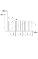
ソレノイド励磁回路67は、図4に示すように、前記したソレノイド46に、直流電源69及びスイッチ素子68を直列接続してなる。そして、ECU60に備えたCPU63が、図示しないロック解除プログラムを実行することでスイッチ素子68をスイッチングし、ロックアーム41を回動させるための駆動電流をソレノイド46に流す。このとき、ECU60は、PWM制御により駆動電流を制御する。そして、EEPROM80には、PWM制御に用いる矩形パルスPの周波数fが記憶されるようになっている。即ち、ECU60に備えたCPU63が、前記ロック解除プログラムを実行すると、CPU63は、EEPROM80から周波数fのデータを取得し、図5に示すように、その周波数fで矩形パルスPを生成する。そして、各矩形パルスPの幅を適宜変更することで駆動電流Iを制御する。より具体的には、ロック解除プログラムを実行すると、図6(B)に示すようにEEPROM80に記憶されたデータが、CPU63の記憶領域におけるタイマレジスタ60Aに格納され、ロック解除プログラムに備えたパルス演算処理60Bが、タイマレジスタ60Aに格納されたデータを周波数fとして取得し、その周波数fで所定幅の矩形パルスPを生成する。
As shown in FIG. 4, the
ところで、ソレノイド46は上記の如く励磁されると、PWM制御で用いた矩形パルスPと同じ周波数fの音源となり得る。そして、ソレノイド46が発する音が車両10の共振周波数と一致すると、音が増幅されて車内に響く。これに対し、矩形パルスPの周波数を高周波に設定するとソレノイド46が高温になり得る。このため、例えば矩形パルスPの周波数は0.3〜1.5[kHz]の範囲に制約される。また、ステアリングシャフト16、ラック12、ラックケース12Cを含む操舵系アッシ(本発明に係る「車両構成部品」に相当する)の組み付け誤差により、それら操舵系アッシ毎にソレノイド46と共振する周波数が異なる。
By the way, when the
これら事情に鑑み、本実施形態では、操舵系アッシが完成したら、図6(A)に示すようにその出荷検査時に、検査装置81をEEPROM80に接続し、周波数を順次変更してEEPROM80に書き込み、ロック解除プログラムを実行してソレノイド46を励磁し、音量を計測する。そして、各周波数毎に共鳴音量を比較して、各操舵系アッシ毎の共振周波数を特定する(本発明に係る「共振周波数計測工程」に相当する)。
In view of these circumstances, in this embodiment, when the steering system assembly is completed, as shown in FIG. 6A, at the time of shipping inspection, the
次いで、操舵系アッシの共振周波数から外れた特定周波数f1を決定する(本発明に係る「特定周波数決定工程」に相当する)。具体的には、共振周波数に対し、例えば0.3[kHz]を加えるか或いは引いて、0.3〜1.5[kHz]の範囲に収まるように、特定周波数f1を決定する。そして、その特定周波数f1を検査装置81がEEPROM80に書き込む(本発明に係る「データ書き込み工程」に相当する)。検査装置81が所定のプログラムを実行することで上記検査及び特定周波数f1の書き込みを自動的に行う。以上により、ECU60の製造が完了する。そして、この操舵系アッシがECU60と共に車両に搭載される。
Next, the specific frequency f1 deviating from the resonance frequency of the steering system assembly is determined (corresponding to the “specific frequency determination step” according to the present invention). Specifically, for example, 0.3 [kHz] is added to or subtracted from the resonance frequency, and the specific frequency f1 is determined so as to be within the range of 0.3 to 1.5 [kHz]. Then, the
このように本実施形態のECU60の製造方法によれば、出荷検査により各操舵系アッシ毎の特定周波数f1を決定して、その場で特定周波数f1をEEPROM80に書き込むので、特定周波数f1のデータROMを別途製作してから実装する場合に比べて作業効率が向上する。そして、このようにして製造されたECU60によれば、操舵系アッシの共振周波数から外れた特定周波数f1の矩形パルスPを用いてPWM制御を行うので車両内の共鳴が防がれ、PWM制御に起因した騒音を低減することができる。
As described above, according to the manufacturing method of the
[第2実施形態]
本実施形態は、前記第1実施形態を変形したものである。以下、第1実施形態と異なる構成に関してのみ説明し、第1実施形態と同一の部位に関しては同一符号を付して重複した説明は省略する。本実施形態のECU60に備えたROM64(本発明に係る「選択肢記憶メモリ」に相当する)には、複数種類の周波数(f10,f11,f12・・・)が識別子(例えば、識別番号)とセットにして記憶されている。また、EEPROM80には、所定の識別子が記憶されており、ECU60のCPU63は、ロック解除プログラムを実行すると、EEPROM80から識別子を取得し、さらに、その識別子と同じ識別子を周した周波数をROM64から取得し、その周波数で所定幅の矩形パルスを生成するようになっている。
[Second Embodiment]
The present embodiment is a modification of the first embodiment. Hereinafter, only the configuration different from that of the first embodiment will be described, and the same parts as those of the first embodiment will be denoted by the same reference numerals and redundant description will be omitted. In the ROM 64 (corresponding to the “option storage memory” according to the present invention) provided in the
このEEPROM80に書き込む識別子を決定するために、検査装置81により、複数種類の周波数(f10,f11,f12・・・)に対応した識別子を順次変更してEEPROM80に書き込み、ロック解除プログラムを実行してソレノイド46を励磁し、音量を計測する。そして、各周波数毎に共鳴音量を比較して、各操舵系アッシ毎の共振周波数を特定する。そして、操舵系アッシの共振周波数から外れた所定の周波数の識別子を決定して、EEPROM80に書き込む。以上説明した本実施形態の構成によっても第1実施形態と同様の作用効果を奏する。
In order to determine the identifier to be written to the
[他の実施形態]
本発明は、前記実施形態に限定されるものではなく、例えば、以下に説明するような実施形態も本発明の技術的範囲に含まれ、さらに、下記以外にも要旨を逸脱しない範囲内で種々変更して実施することができる。
[Other Embodiments]
The present invention is not limited to the above-described embodiment. For example, the embodiments described below are also included in the technical scope of the present invention, and various other than the following can be made without departing from the scope of the invention. It can be changed and implemented.
(1)前記実施形態のEEPROM80には1つの特定周波数f1が記憶されていたが、操舵系アッシの共振周波数から外れた特定周波数を複数決定し、それら複数の特定周波数をEEPROMに記憶していてもよい。そして、矩形パルスの周波数を、EEPROMに記憶された複数の特定周波数に切り替えてPWM制御を行う構成にしてもよい。
(1) Although one specific frequency f1 is stored in the
(2)前記第1実施形態では、操舵系アッシ毎の共振周波数を特定してEEPROM80に書き込んでいたが、操舵系アッシを搭載した車両毎に共振周波数を計測し、その共振周波数から外れた特定周波数をEEPROMに書き込む構成にしてもよい。
(2) In the first embodiment, the resonance frequency for each steering system assembly is specified and written in the
(3)前記第1実施形態は特定周波数f1又は識別子を記憶するためにEEPROM80を備えていたが、ECU60に実装した状態でデータを書き込み可能なものであれば、EEPROM以外のメモリであってもよい。
(3) Although the first embodiment includes the
10 車両
11 転舵輪
46 ソレノイド
60 ECU
67 ソレノイド励磁回路
68 スイッチ素子
80 EEPROM
10
67
Claims (4)
前記車両部品駆動制御回路に実装された状態でデータを書き込み可能なパラメータ記憶メモリを設け、前記パラメータ記憶メモリに前記車両又は車両構成部品の共振周波数から外れた特定周波数を記憶し、そのパラメータ記憶メモリから取得した前記特定周波数で矩形パルスを生成して前記PWM制御を行うように構成したことを特徴とする車両部品駆動制御回路。 In a vehicle component drive control circuit that performs PWM control of a drive current to an electric device mounted on a vehicle,
A parameter storage memory capable of writing data in a state of being mounted on the vehicle component drive control circuit is provided, a specific frequency deviating from a resonance frequency of the vehicle or vehicle component is stored in the parameter storage memory, and the parameter storage memory A vehicle component drive control circuit configured to perform the PWM control by generating a rectangular pulse at the specific frequency acquired from
複数種類の周波数とそれらを識別するための識別子とをセットにして記憶した選択肢記憶メモリと、前記車両部品駆動制御回路に実装された状態でデータを書き込み可能なパラメータ記憶メモリとを設け、
前記複数種類の周波数のうち前記車両又は車両構成部品の共振周波数から外れた周波数の前記識別子を前記パラメータ記憶メモリに記憶し、
前記パラメータ記憶メモリから前記識別子を取得すると共にその識別子に対応した周波数を前記選択肢記憶メモリから取得し、その周波数で矩形パルスを生成して前記PWM制御を行うように構成したことを特徴とする車両部品駆動制御回路。 In a vehicle component drive control circuit that performs PWM control of a drive current to an electric device mounted on a vehicle,
An option storage memory that stores a plurality of types of frequencies and identifiers for identifying them as a set, and a parameter storage memory that can write data in a state of being mounted on the vehicle component drive control circuit,
Storing the identifier of the frequency out of the resonance frequency of the vehicle or vehicle component among the plurality of types of frequencies in the parameter storage memory;
A vehicle configured to acquire the identifier from the parameter storage memory, acquire a frequency corresponding to the identifier from the option storage memory, generate a rectangular pulse at the frequency, and perform the PWM control. Component drive control circuit.
前記パラメータ記憶メモリを前記車両部品駆動制御回路に実装された状態でデータを書き込み可能な構成としておき、
車両毎又は車両構成部品毎の共振周波数を計測する共振周波数計測工程と、
車両毎又は車両構成部品毎に共振周波数から外れた特定周波数を決定する特定周波数決定工程と、
前記特定周波数決定工程で決定された前記特定周波数を前記パラメータ記憶メモリに書き込むデータ書き込み工程とを行うことを特徴とする車両部品駆動制御回路の製造方法。 A specific frequency deviating from the resonance frequency of the vehicle or vehicle component is stored in a parameter storage memory, a rectangular pulse is generated at the specific frequency acquired from the parameter storage memory, In the manufacturing method of the vehicle component drive control circuit for PWM control of the drive current,
The parameter storage memory is configured so that data can be written in a state mounted in the vehicle component drive control circuit,
A resonance frequency measuring step for measuring a resonance frequency for each vehicle or each vehicle component;
A specific frequency determining step for determining a specific frequency deviating from the resonance frequency for each vehicle or each vehicle component;
A vehicle component drive control circuit manufacturing method comprising: performing a data writing step of writing the specific frequency determined in the specific frequency determination step into the parameter storage memory.
前記パラメータ記憶メモリを前記車両部品駆動制御回路に実装された状態でデータを書き込み可能な構成としておき、
車両毎又は車両構成部品毎の共振周波数を計測する共振周波数計測工程と、
前記選択肢記憶メモリに記憶された複数種類の周波数のうち、各車両毎又は各車両構成部品毎にそれらの共振周波数から外れた周波数の識別子を決定する識別子決定工程と、
前記識別子決定工程で決定された前記識別子を前記パラメータ記憶メモリに書き込むデータ書き込み工程とを行う備ことを特徴とする車両部品駆動制御回路の製造方法。
A plurality of types of frequencies and identifiers for identifying them are stored as a set in the option storage memory, the predetermined identifier is stored in the parameter storage memory, and the identifier is acquired from the parameter storage memory. In the method of manufacturing a vehicle component drive control circuit that obtains a frequency corresponding to the identifier from the option storage memory, generates a rectangular pulse at the frequency, and performs PWM control of a drive current to an electric device mounted on the vehicle.
The parameter storage memory is configured so that data can be written in a state mounted in the vehicle component drive control circuit,
A resonance frequency measuring step for measuring a resonance frequency for each vehicle or each vehicle component;
An identifier determination step for determining an identifier of a frequency deviating from the resonance frequency for each vehicle or for each vehicle component among a plurality of types of frequencies stored in the option storage memory;
A method for manufacturing a vehicle component drive control circuit, comprising: a data writing step of writing the identifier determined in the identifier determination step into the parameter storage memory.
Priority Applications (1)
| Application Number | Priority Date | Filing Date | Title |
|---|---|---|---|
| JP2005121983A JP2006304473A (en) | 2005-04-20 | 2005-04-20 | Vehicle component drive control circuit and manufacturing method therefor |
Applications Claiming Priority (1)
| Application Number | Priority Date | Filing Date | Title |
|---|---|---|---|
| JP2005121983A JP2006304473A (en) | 2005-04-20 | 2005-04-20 | Vehicle component drive control circuit and manufacturing method therefor |
Publications (1)
| Publication Number | Publication Date |
|---|---|
| JP2006304473A true JP2006304473A (en) | 2006-11-02 |
Family
ID=37472117
Family Applications (1)
| Application Number | Title | Priority Date | Filing Date |
|---|---|---|---|
| JP2005121983A Pending JP2006304473A (en) | 2005-04-20 | 2005-04-20 | Vehicle component drive control circuit and manufacturing method therefor |
Country Status (1)
| Country | Link |
|---|---|
| JP (1) | JP2006304473A (en) |
Cited By (2)
| Publication number | Priority date | Publication date | Assignee | Title |
|---|---|---|---|---|
| JP2015005117A (en) * | 2013-06-20 | 2015-01-08 | 株式会社デンソー | Load drive control device |
| WO2015173972A1 (en) * | 2014-05-15 | 2015-11-19 | 三井金属アクト株式会社 | Door opening/closing device and door opening/closing method |
-
2005
- 2005-04-20 JP JP2005121983A patent/JP2006304473A/en active Pending
Cited By (8)
| Publication number | Priority date | Publication date | Assignee | Title |
|---|---|---|---|---|
| JP2015005117A (en) * | 2013-06-20 | 2015-01-08 | 株式会社デンソー | Load drive control device |
| WO2015173972A1 (en) * | 2014-05-15 | 2015-11-19 | 三井金属アクト株式会社 | Door opening/closing device and door opening/closing method |
| JP2015218466A (en) * | 2014-05-15 | 2015-12-07 | 三井金属アクト株式会社 | Door opening/closing device and door opening/closing method |
| CN105283332A (en) * | 2014-05-15 | 2016-01-27 | 三井金属爱科特株式会社 | Door opening/closing device and door opening/closing method |
| US20160087565A1 (en) * | 2014-05-15 | 2016-03-24 | Mitsui Kinzoku Act Corporation | Door opening/closing device and door opening/closing method |
| EP2974895A4 (en) * | 2014-05-15 | 2016-11-09 | Mitsui Kinzoku Act Corp | Door opening/closing device and door opening/closing method |
| CN105283332B (en) * | 2014-05-15 | 2017-08-22 | 三井金属爱科特株式会社 | Device for opening/closing door and door method for opening and closing |
| US10135371B2 (en) | 2014-05-15 | 2018-11-20 | Mitsui Kinzoku Act Corporation | Door opening/closing device and door opening/closing method |
Similar Documents
| Publication | Publication Date | Title |
|---|---|---|
| JP4567575B2 (en) | Rotation angle detector | |
| JP6012154B2 (en) | Brushless motor for electric power steering apparatus and manufacturing method thereof | |
| JP5097364B2 (en) | Rotation connector device with built-in rudder angle sensor | |
| CN102570722B (en) | There is the EPS motor of steering angle sensor | |
| JP4407120B2 (en) | Vehicle steering system | |
| JP2008007075A (en) | Steering angle sensor built-in type rotary connector device | |
| JP4279702B2 (en) | Rotation drive | |
| JP4218645B2 (en) | Liquid level detector | |
| JP4678254B2 (en) | Steer-by-wire system | |
| JP2005180653A (en) | Abnormality diagnostic device of motor driving system | |
| JP2006304473A (en) | Vehicle component drive control circuit and manufacturing method therefor | |
| JP2005055321A (en) | Assembly method of torque sensor, torque sensor, and electric power steering device | |
| JP4333661B2 (en) | Electric power steering device | |
| JP7228405B2 (en) | Control circuit and motor controller | |
| JP2005037254A (en) | Rotation angle detection device and rotation angle detection method | |
| JP2007113524A (en) | Vehicle control device | |
| JP4692743B2 (en) | Steering system | |
| JP4380317B2 (en) | Correction value detection method for torque sensor device | |
| JP2008008676A (en) | Indicating instrument for vehicle | |
| JP4548654B2 (en) | Steering device | |
| JP5071313B2 (en) | Indicators for vehicles | |
| JP5003784B2 (en) | Indicators for vehicles | |
| JP3799767B2 (en) | Proportional solenoid for electric power steering system | |
| JP4240205B2 (en) | Steering system transmission ratio variable system | |
| JP2004279295A (en) | Power steering device |