JP2006300902A - Stress detection method and device - Google Patents
Stress detection method and device Download PDFInfo
- Publication number
- JP2006300902A JP2006300902A JP2005127110A JP2005127110A JP2006300902A JP 2006300902 A JP2006300902 A JP 2006300902A JP 2005127110 A JP2005127110 A JP 2005127110A JP 2005127110 A JP2005127110 A JP 2005127110A JP 2006300902 A JP2006300902 A JP 2006300902A
- Authority
- JP
- Japan
- Prior art keywords
- stress
- permanent magnet
- shaft
- magnetic
- magnetic flux
- Prior art date
- Legal status (The legal status is an assumption and is not a legal conclusion. Google has not performed a legal analysis and makes no representation as to the accuracy of the status listed.)
- Withdrawn
Links
Images


Abstract
Description
本発明は、各種機械の部材に作用する応力の検出技術に係わり、具体的には磁歪の逆効果を利用して、磁歪を有する部材にかかる応力を非接触で検出する応力検出方法及び装置に関するものである。 The present invention relates to a technique for detecting stress acting on members of various machines, and more specifically, to a stress detection method and apparatus for detecting a stress applied to a member having magnetostriction in a non-contact manner by utilizing an inverse effect of magnetostriction. Is.
例えば、自動車における足回りの軸力を、廉価で、ロバスト性に優れたセンサによって検知できるようになれば、新たな車輌制御の実現につながる可能性があるため、廉価で小型な応力センサの潜在的な要望は少なくないものと考えられるが、そのようなセンサの候補が見当たらないのが現状である。 For example, if the axial force of an undercarriage in an automobile can be detected by an inexpensive and highly robust sensor, it may lead to the realization of new vehicle control. It is thought that there are many requests, but at present there are no such sensor candidates.
弾性を有する部材の応力を検出する方法としては、歪ゲージを貼る方法がよく知られているが、自動車等の足回りのリンクの軸力(引張、圧縮力)を検知するためには、ロバスト性が要求されることから、歪ゲージによる上記方法がこれに適しているとは言えない。
一方、応力センサとして、磁歪を利用したセンサの提案がなされているものの、実用化されているものはないようである(例えば、非特許文献1参照)。
On the other hand, although a sensor using magnetostriction has been proposed as a stress sensor, none seems to be put into practical use (for example, see Non-Patent Document 1).
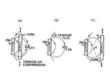
すなわち、図13は、上記非特許文献1によって提案されている磁歪の逆効果を利用した応力センサの説明図であって、図13(a)において、PMは永久磁石、FSは磁気センサであり、中央に位置するコアは磁歪を有している。永久磁石PMからの磁束は、図のように分布し、コアを矢印のように磁化すると共に、上記磁束はコアをも通っている。
コアに引張応力が働くと、磁束がコアをより多く通るようになるために、磁気センサFSを通過する磁束が減少する。一方、コアに圧縮応力が作用すると、磁束はコアを通り難くなるため、磁気センサFSを通過する磁束が増加する。このようにして、センサFSからの信号の大きさはコアに働く応力の大きさを反映することになる。
That is, FIG. 13 is an explanatory diagram of a stress sensor using the inverse effect of magnetostriction proposed by Non-Patent
When tensile stress is applied to the core, the magnetic flux passes through the core more, so the magnetic flux passing through the magnetic sensor FS decreases. On the other hand, when compressive stress acts on the core, the magnetic flux is difficult to pass through the core, and thus the magnetic flux passing through the magnetic sensor FS increases. In this way, the magnitude of the signal from the sensor FS reflects the magnitude of the stress acting on the core.
以上が提案されている応力センサの原理であり、磁束を発生させるのに電源がいらない点が特徴である。磁気センサFSの位置としては、図13(c)に示されているように、A又はBの位置でもよいことが述べられている。
引張応力と圧縮応力では、センサFSの信号の変化の仕方は、圧縮の方が大きく、そのセンサの定格の範囲において、圧縮にて30から80%の変化があることがデータで示されている。
The above is the principle of the proposed stress sensor, which is characterized in that no power source is required to generate magnetic flux. It is stated that the position of the magnetic sensor FS may be the position of A or B as shown in FIG.
In tensile stress and compressive stress, the data shows that the signal of the sensor FS changes more greatly in compression, and in the rated range of the sensor, there is a change of 30 to 80% in compression. .
しかしながら、上記提案においては、パイプ状のコアの中に円筒状のアルニコ磁石を配置し、パイプの表面に、ホール素子を置いてデータが取られており、原理確認段階の域にあり、上記したように、実用化段階の提案とは言えない。 However, in the above proposal, the cylindrical alnico magnet is arranged in the pipe-shaped core, and the Hall element is placed on the surface of the pipe, and the data is taken. Thus, it cannot be said that it is a proposal at the practical application stage.
本発明は、従来の応力センサにおける上記課題に鑑みてなされたものであって、その目的とするところは、磁歪の逆効果を利用した応力センサを実用化し、ロバスト性に優れた応力検出方法と、このような検出方法を適用した廉価な応力検出装置を提供することにある。 The present invention has been made in view of the above-described problems in conventional stress sensors, and the object of the present invention is to commercialize a stress sensor using the inverse effect of magnetostriction and to provide a stress detection method with excellent robustness. Another object of the present invention is to provide an inexpensive stress detection apparatus to which such a detection method is applied.
本発明者らは、上記課題の解決に向けて鋭意検討した結果、着磁した磁性体が磁歪を有する磁性体の側にあれば、実用的な応力センサになることを見出し、本発明を完成するに到った。 As a result of intensive studies aimed at solving the above problems, the present inventors have found that if a magnetized magnetic body is on the side of a magnetic body having magnetostriction, the present invention can be a practical stress sensor, and the present invention has been completed. I arrived.
本発明は上記知見に基づくものであって、本発明の応力検出方法は、永久磁石から発生した磁束が、この永久磁石の近傍にあって磁歪を有する磁性体を通る内部磁束と、この磁性体を通ることなく空間に流れる空間磁束と分配され、上記磁性体に応力が作用することによって、磁性体を通る内部磁束の量が変化すると、磁性体外の空間を流れる空間磁束の量が変化する現象を利用したものであって、このような空間磁束の変化を上記永久磁石に対して磁性体と異なる側において検知することによって、上記磁性体に作用する応力を検出するようにしたことを特徴としている。 The present invention is based on the above knowledge, and the stress detection method of the present invention is such that the magnetic flux generated from the permanent magnet is in the vicinity of the permanent magnet and passes through the magnetic body having magnetostriction, and the magnetic body. Phenomenon in which the amount of spatial magnetic flux that flows in the space outside the magnetic material changes when the amount of internal magnetic flux that passes through the magnetic material changes due to the stress acting on the magnetic material that is distributed to the space without flowing through the space It is characterized in that the stress acting on the magnetic body is detected by detecting such a change in the spatial magnetic flux on a side different from the magnetic body with respect to the permanent magnet. Yes.
また、本発明の応力検出装置は、上記検出方法を実施するのに好適に用いることができ、磁歪を有する磁性体と、この磁性体の近傍位置に配設された永久磁石と、上記磁性体に応力が作用することによって、永久磁石から発生し上記磁性体を通ることなく磁性体外の空間に流れる空間磁束が変化するのを検知する空間磁束検出手段を備えたものであって、例えば磁気センサなどの空間磁束検出手段が上記磁性体に対して永久磁石と異なる側に配設されている構成としたことを特徴としている。 The stress detection apparatus of the present invention can be suitably used for carrying out the above detection method, and includes a magnetic body having magnetostriction, a permanent magnet disposed in the vicinity of the magnetic body, and the magnetic body. Including a magnetic flux detection means for detecting a change in the magnetic flux generated from the permanent magnet and flowing in the space outside the magnetic material without passing through the magnetic material, for example, a magnetic sensor The spatial magnetic flux detection means such as is arranged on the side different from the permanent magnet with respect to the magnetic body.
磁歪を有する磁性体と永久磁石とを接近させて配置すると、永久磁石から出ている磁束が上記磁性体を通る内部磁束と、この磁性体外の空間に流れる空間磁束と分配されて流れ、磁性体に応力が働くと、この磁性体を通る内部磁束の量が変化し、その結果上記空間を流れる空間磁束の量が変化するので、この空間磁束の変化を磁気センサなどの空間磁束検出手段、さらに具体的には、ホール素子やホールICなどによって検知することによって、上記磁性体に作用する応力を検出することができる。
本発明によれば、このような空間磁束の変化を永久磁石に対して上記磁性体と異なる側において検知するようにしているので、微小な磁界変化を検出することができ、磁性体に作用する応力の検出感度を向上させることができる。また、永久磁石を磁性体と一体的に配置したり、磁性体を軸状にしたりすることによって、部品点数の少ないコンパクトで、安価な装置の実現が可能となると共に、回転状態における応力検出も可能となってその有用性を飛躍的に向上させることができる。
When a magnetic body having magnetostriction and a permanent magnet are arranged close to each other, the magnetic flux emitted from the permanent magnet flows in a distributed manner with the internal magnetic flux passing through the magnetic body and the spatial magnetic flux flowing in the space outside the magnetic body. When the stress acts on the magnetic material, the amount of the internal magnetic flux passing through the magnetic body changes, and as a result, the amount of the spatial magnetic flux flowing through the space changes, so that the change in the spatial magnetic flux is detected by a spatial magnetic flux detecting means such as a magnetic sensor, Specifically, the stress acting on the magnetic material can be detected by detecting with a Hall element or Hall IC.
According to the present invention, such a change in the spatial magnetic flux is detected on the side different from the magnetic body with respect to the permanent magnet, so that a minute magnetic field change can be detected and acts on the magnetic body. Stress detection sensitivity can be improved. In addition, by arranging the permanent magnet integrally with the magnetic body, or by making the magnetic body into a shaft shape, it is possible to realize a compact and inexpensive device with a small number of parts, and it is also possible to detect stress in a rotating state. It becomes possible and the usefulness can be dramatically improved.
以下、本発明の応力検出方法及び応力検出装置について、その実施の具体的形態と共にさらに詳細に説明する。 Hereinafter, the stress detection method and the stress detection apparatus of the present invention will be described in more detail together with specific embodiments thereof.
本発明の応力検出方法及び装置は、基本的に上記構成のものであるが、上記磁性体を軸状のものとすることや、上記永久磁石を軸状磁性体の表面に接して配置することが望ましい。 The stress detection method and apparatus according to the present invention basically have the above-described configuration. However, the magnetic body is axial, or the permanent magnet is disposed in contact with the surface of the axial magnetic body. Is desirable.
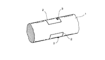
すなわち、本発明の応力検出装置は、例えば図1(a)に示すような構造を有し、磁歪を有する軸1(磁性体)を備え、軸1の図中央部には、薄肉円筒状の永久磁石2が嵌合されている。なお、上記永久磁石2は、軸方向に着磁されている。
That is, the stress detection device of the present invention has a structure as shown in FIG. 1A, for example, and includes a shaft 1 (magnetic material) having magnetostriction. A
図1(a)において、符号3は、空間磁束検出手段としての磁気センサであって、具体的にはホールセンサが用いられる。
磁気センサ3としては、上記したホールセンサの他には、省電力で小型なホールICやMIセンサなどを使用することができるが、検出感度を大きくする観点から、図に示すように、永久磁石2の端部に近い位置に配置することによって、径方向の磁束を検知するようになすことが望ましい(図1(b)参照)。ここで言うホールICとは、リニア出力の得られるタイプのものである
In FIG. 1A,
As the
図1(b)は、永久磁石2の断面図であって、当該永久磁石2の磁束は、軸1の内部と軸1の外の空間を流れてクローズしている。
FIG. 1B is a cross-sectional view of the
上記軸1に、軸方向の引張応力が働くと、軸1を通る磁束が増える(磁束が軸の内部を通り易くなる)から、外に漏れる空間磁束が減り、したがって磁気センサ3を通過する磁束が減ることになる。なお、これは、磁歪が正の場合の説明であって(以下、同様とする)、磁歪が負の場合は当然この逆となる。
一方、軸1に圧縮応力が働くと、軸1を通る磁束が減る(磁束が軸の内部を通り難くなる)ことから、外に漏れる空間磁束が増え、磁気センサ3を通過する磁束が増える。したがって、応力に対応した磁気センサ3の信号が得られることになる。
When an axial tensile stress acts on the
On the other hand, when compressive stress is applied to the
このような構造を有する本発明の応力検出装置においては、磁気センサ3を軸1に接触させる必要がないので、非接触状態で、軸力(引張、圧縮応力)の検知が可能である。
また、応力が作用する磁性体を軸状のものとしたことによって、回転状態での軸力(引張、圧縮応力)の測定も可能となる。なお、上記永久磁石2は、磁束の供給源として機能するものであって、応力を受けて軸1と共に変形する必要はない。
In the stress detection device of the present invention having such a structure, since it is not necessary to bring the
In addition, the axial force (tensile and compressive stress) in the rotating state can be measured by using a magnetic material on which the stress acts as a shaft. The
磁気センサ3の裏側(反軸側)には、図2(a)及び(b)に示すように、珪素鋼板、電磁軟鉄、ソフトフェライト、パーマロイなど、保磁力の小さいソフト磁性材料から成るヨーク5を配設することもできる。
このようなヨーク5を用いると、外部からの電磁雑音に対して耐性が向上することになると共に、磁気センサ3の信号の大きさを倍程度に増やすことが可能となる。
As shown in FIGS. 2A and 2B, a
When such a
また、図3に示すように、磁気センサを2個使用することもできる。すなわち、上記磁気センサ3に加えて第2の磁気センサ4を軸方向に並べ、これらを上記凹凸部2の両端近傍位置にそれぞれ配置することが望ましい。この場合、第2の磁気センサ4については、センサ感度のセンスが逆になるので、減算することによって2つのセンサ信号が加算されて2倍にすることができる。
このように2個のセンサ3,4を配置することによって、外部からのほぼ一様な磁場が印加されても、同相の入力となるから、引き算でキャンセルすることができ、外乱に対する耐性が向上する。
Also, as shown in FIG. 3, two magnetic sensors can be used. That is, it is desirable to arrange the second magnetic sensor 4 in the axial direction in addition to the
By arranging the two
図4は、軸1の表面にシート状の永久磁石2を配置した場合を示す。永久磁石2は、図中に矢印で示すように、軸1の長手方向(軸方向)に着磁されている。永久磁石2としては、ボンド磁石でもよいし、アルニコ等のシート状金属磁石でもよい。なお、シート状の磁石2は、長手方向に着磁された場合の磁石特性が極めて安定なものとなることから、好都合である。
磁気センサ3は、シート磁石磁石2の端部上方に配すればよい。
FIG. 4 shows a case where a sheet-like
The
また、図5に示すように、上記永久磁石2の裏面側(180度位置)に永久磁石2をもう一つ配置することもできる。
この場合、磁気センサの信号を倍化できるとともに、軸1の径が小さい場合など、軸1に曲げ応力がかかる場合に、曲げ応力分をキャンセルすることができ、軸力のみを検知できるというメリットが生じる。
Further, as shown in FIG. 5, another
In this case, the signal of the magnetic sensor can be doubled, and when the bending stress is applied to the
図6は、軸1に縮径部1aを設けた場合の断面図であって、このように縮径部1aを形成することによって、永久磁石2の位置固定が容易なものとなる。
FIG. 6 is a cross-sectional view when the reduced diameter portion 1a is provided on the
さらに、以上の説明においては、磁歪を有する磁性体として、軸状を成すものを用いた例を示したが、図7に示すように、板状の磁性体10であっても応力検出装置として機能することは言うまでもない。
図に示すように、長手方向に着磁されたシート状の永久磁石2を板表面に配置すると共に、当該永久磁石2の端部上方に、磁気センサ3を同様に配置する。
Further, in the above description, an example in which a shaft-like magnetic body is used as a magnetic body having magnetostriction has been shown. However, as shown in FIG. 7, even a plate-like
As shown in the drawing, a sheet-like
磁歪を有する磁性体としては、応力に対するヒステリシスは少ないことが望まれるため、上記磁性体材料は適切な工程を経る必要がある。例えば、機械加工後、熱処理工程を入れたり、熱処理後、不均一な残留応力が入らないように機械加工を行なったりすることが望ましい。周方向に着磁することも、有効な手段と言うことができる。
すなわち、図8に示すように、軸1を周方向に着磁し(永久磁石2とは、着磁の向きが直交している)、周方向に向いている磁化が多いことが、ヒステリシス低減に効いているものと考えられる。また、周方向に着磁することのメリットは、引張、圧縮の感度が同じようになることである(応力磁気効果は、一般的には圧縮の方が大きい)。この理由も同じであるものと推定される。
Since it is desired that the magnetic material having magnetostriction has little hysteresis with respect to stress, the magnetic material needs to undergo an appropriate process. For example, it is desirable to perform a heat treatment process after machining, or to perform machining so that non-uniform residual stress does not enter after heat treatment. Magnetizing in the circumferential direction can also be said to be an effective means.
That is, as shown in FIG. 8, the
なお、軸材に通電すると、電流密度が一様な場合、周方向磁界の大きさは、軸内では半径に比例した大きさになり、軸外では、中心からの距離に反比例して減衰する。
一般に、軸材料の持つ保磁力の大きさの2倍以上の磁界がかかった部分が概ね着磁されることになる。したがって、十分な大きさの電流を流した場合、表面を含めた円筒領域においては、確実に周方向に着磁されることになる。
When the shaft material is energized, when the current density is uniform, the magnitude of the circumferential magnetic field is proportional to the radius inside the shaft and attenuates inversely proportional to the distance from the center outside the shaft. .
In general, a portion to which a magnetic field twice or more as large as the coercive force of the shaft material is applied is generally magnetized. Therefore, when a sufficiently large current is passed, the cylindrical region including the surface is surely magnetized in the circumferential direction.
また、上記磁性体に負荷される応力が大きい方が大きな出力信号が得られることから、軸の場合には中空軸とすることによって感度の増大を図ることができる。 Further, since a larger output signal is obtained when the stress applied to the magnetic body is larger, the sensitivity can be increased by using a hollow shaft in the case of a shaft.
図9(a)及び(b)は、薄肉円筒状磁石の端部に多極着磁部を設けることによって、回転センサとしても機能するようにした例を示すものである。
すなわち、薄肉円筒状永久磁石2として、少し長めのボンド磁石を採用し、図中左側の端部をNSの多極着磁部2aとする。このときの着磁方向は、図9(b)に示すように径方向である。
FIGS. 9A and 9B show examples in which a multipolar magnetized portion is provided at the end of a thin cylindrical magnet so as to function as a rotation sensor.
That is, a slightly longer bonded magnet is employed as the thin cylindrical
一方、薄肉円筒状永久磁石2における応力検出用の磁束を供給する部分の着磁方向は、図9(a)に示すように軸方向である。当該永久磁石2を構成するボンド磁石としては、フェライトボンドでもよいし、希土類のボンド磁石でもよい。
そして、上記永久磁石2の多極着磁部2aにホールIC7を対向させることによって、軸1の回転信号を応力検出と同時にとることができる。
On the other hand, the magnetization direction of the portion supplying the magnetic flux for stress detection in the thin cylindrical
Then, by making the Hall IC 7 face the multipolar
このようにして、回転センサと兼ねた応力検出装置を実現することができる。なお、ここで上記ホールIC7としては、パルス出力であるディジタル出力タイプのものを採用した。 In this way, a stress detection device that also serves as a rotation sensor can be realized. Here, as the Hall IC 7, a digital output type that is a pulse output is adopted.
上記応力検出装置において、センサ特性を安定化するには、使用温度より高い温度でエージングするとよい。
センサを仕立てた状態にて、例えば160℃にて1時間程度エージングすることによって、当該温度以下の温度での使用に際して、安定した特性とすることができる。
In the stress detection apparatus, in order to stabilize the sensor characteristics, aging is preferably performed at a temperature higher than the use temperature.
By aging the sensor for about 1 hour at, for example, 160 ° C., stable characteristics can be obtained when used at a temperature equal to or lower than that temperature.
以下、本発明を実施例に基づいて具体的に説明する。なお、本発明は、これらの実施例のみに限定されることはない。 Hereinafter, the present invention will be specifically described based on examples. In addition, this invention is not limited only to these Examples.
(実施例1)
磁歪を有する磁性体材料として、マルエージング鋼(日立金属(株)製商品名YAG300、18%Ni−9%Co−5%Mo−Fe)を用いて、図1に示すように、軸径D=19mmの軸1を機械加工によって作製した。
機械加工の後、固溶化および時効熱処理を施した。固溶化処理は真空中にて820℃×1h、時効処理は真空中にて490℃×5h保持し、その後空冷した。
Example 1
As a magnetic material having magnetostriction, maraging steel (trade name YAG300, manufactured by Hitachi Metals, Ltd., 18% Ni-9% Co-5% Mo-Fe) is used, and as shown in FIG. = 19
After machining, solution treatment and aging heat treatment were performed. The solution treatment was held at 820 ° C. × 1 h in vacuum, the aging treatment was held at 490 ° C. × 5 h in vacuum, and then air-cooled.
永久磁石2としては、幅12mm、厚さ1mmの薄肉円筒状フェライト磁石を幅方向に着磁して用いた。薄肉円筒状フェライト磁石単体での着磁後の端面の漏れ磁界は約1.5kGであった。
As the
そして、図1に示すように、薄肉円筒状永久磁石2を軸1に嵌合すると共に、当該永久磁石2の端部上方位置にホールセンサ3を配置し、軸1に引張及び圧縮応力を印加した時のホールセンサ3の出力を調べた。その結果を図10に示す。なお、ホールセンサ3の感磁エリアは約2mm2であって、エリアの中心位置を軸1の表面から約0.5mmとした。ホールセンサ3は径方向の磁界を検知することになる。
ホールセンサ3からの出力は、軸1が引張応力を受けることにより減少、圧縮応力によって増加し、±40MPaの応力負荷に対して、ヒステリシスのほとんどない特性が得られることが確認された。
Then, as shown in FIG. 1, the thin cylindrical
It was confirmed that the output from the
なお、応力0におけるデータがないが、これは当該実施例に用いた試験機の都合によるものである。すなわち、引張応力と圧縮応力を連続的に負荷するようにした当該試験機においては、ガタが発生して、連続的な出力が取れなかったことによる。したがって、ガタの発生が防止できるように装置に工夫を加えることによって、解消できるものと考えられる。
また、応力負荷範囲が狭いが、これも試験機の都合によるものであって、容量の大きな試験機を用いれば、応力範囲を容易に拡大することができる。
There is no data for stress 0, but this is due to the convenience of the testing machine used in this example. That is, in the test machine in which tensile stress and compressive stress are continuously applied, play occurs and continuous output cannot be obtained. Therefore, it is considered that the problem can be solved by adding a device to the apparatus so as to prevent the occurrence of play.
Moreover, although the stress load range is narrow, this is also due to the convenience of the testing machine. If a testing machine with a large capacity is used, the stress range can be easily expanded.
磁歪の逆効果を用いた応力センサにおいては、軸1がミクロな降伏を起こすとヒステリシスが現われてしまうことから、負荷応力が軸1を構成する磁性材料の降伏応力の半分程度以下であれば、再現性のよい特性が得られることになる。
当該実施例においては、上記軸1の材料として用いたマルエージング鋼の降伏応力は2GPaを超えることから、少なくとも1GPa程度までは、十分に再現性の良いデータが得られるものと考えられる。
In a stress sensor using the inverse effect of magnetostriction, hysteresis appears when the
In this example, since the yield stress of the maraging steel used as the material of the
(実施例2)
実施例1と同じ軸材1を使用し、これに10000Aの電通を通すことによって、周方向に着磁した。
これ以外は、上記実施例1と同様の操作を繰り返し、ホールセンサ3からの出力を調べた。その結果、±40MPaの応力負荷に対して、ヒステリシスのほとんどない特性が得られることが確認された。なお、感度は、図10に示した上記実施例1の場合と、若干劣っていた。
(Example 2)
The
Except for this, the same operation as in Example 1 was repeated, and the output from the
(実施例3)
軸1の材料として、JIS G4051に規定される機械構造用炭素鋼S45Cを用いると共に、熱処理として高周波焼入れを施し、次いで170℃×1時間の焼戻し処理を行った。これ以外は、上記実施例2と同じ操作を繰り返すことによってホールセンサ3の出力特性を調査した。
なお、上記熱処理の狙いとしては、焼戻し後の表面硬さをHRC50以上、HRC45以上となる有効硬化層深さを0.8mm狙いとした。
(Example 3)
As a material for the
In addition, as the aim of the above heat treatment, the effective hardened layer depth at which the surface hardness after tempering is HRC50 or more and HRC45 or more is aimed at 0.8 mm.
その結果、ヒステリシスのほとんどない特性が得られた。なお、感度としては、上記実施例2の場合と同等であることが確認された。 As a result, characteristics with almost no hysteresis were obtained. The sensitivity was confirmed to be the same as in Example 2 above.
1 軸(磁性体)
1a 縮径部
2 永久磁石
2a 多極着磁部
3,4 磁気センサ(空間磁束検出手段)
5 ヨーク
1 axis (magnetic material)
DESCRIPTION OF SYMBOLS 1a Reduced
5 York
Claims (21)
Priority Applications (1)
| Application Number | Priority Date | Filing Date | Title |
|---|---|---|---|
| JP2005127110A JP2006300902A (en) | 2005-04-25 | 2005-04-25 | Stress detection method and device |
Applications Claiming Priority (1)
| Application Number | Priority Date | Filing Date | Title |
|---|---|---|---|
| JP2005127110A JP2006300902A (en) | 2005-04-25 | 2005-04-25 | Stress detection method and device |
Publications (1)
| Publication Number | Publication Date |
|---|---|
| JP2006300902A true JP2006300902A (en) | 2006-11-02 |
Family
ID=37469348
Family Applications (1)
| Application Number | Title | Priority Date | Filing Date |
|---|---|---|---|
| JP2005127110A Withdrawn JP2006300902A (en) | 2005-04-25 | 2005-04-25 | Stress detection method and device |
Country Status (1)
| Country | Link |
|---|---|
| JP (1) | JP2006300902A (en) |
Cited By (3)
| Publication number | Priority date | Publication date | Assignee | Title |
|---|---|---|---|---|
| WO2009133812A1 (en) | 2008-04-28 | 2009-11-05 | 住友電工スチールワイヤー株式会社 | Device for measuring tension |
| JP2011095033A (en) * | 2009-10-28 | 2011-05-12 | Sumitomo Denko Steel Wire Kk | Tension measurement method |
| JP2014092390A (en) * | 2012-11-01 | 2014-05-19 | Sumitomo Denko Steel Wire Kk | Tension measurement method |
-
2005
- 2005-04-25 JP JP2005127110A patent/JP2006300902A/en not_active Withdrawn
Cited By (6)
| Publication number | Priority date | Publication date | Assignee | Title |
|---|---|---|---|---|
| WO2009133812A1 (en) | 2008-04-28 | 2009-11-05 | 住友電工スチールワイヤー株式会社 | Device for measuring tension |
| JP2009265003A (en) * | 2008-04-28 | 2009-11-12 | Kyoto Univ | Tension measurement device |
| US20100315076A1 (en) * | 2008-04-28 | 2010-12-16 | Sumitomo (Sei) Steel Wire Corp. | Tension measurement apparatus |
| US8890516B2 (en) | 2008-04-28 | 2014-11-18 | Sumitomo (Sei) Steel Wire Corp. | Tension measurement apparatus |
| JP2011095033A (en) * | 2009-10-28 | 2011-05-12 | Sumitomo Denko Steel Wire Kk | Tension measurement method |
| JP2014092390A (en) * | 2012-11-01 | 2014-05-19 | Sumitomo Denko Steel Wire Kk | Tension measurement method |
Similar Documents
| Publication | Publication Date | Title |
|---|---|---|
| KR100365836B1 (en) | Collarless circularly magnetized torque transducer and method for measuring torque using same | |
| JP5684442B2 (en) | Magnetic sensor device | |
| KR100677920B1 (en) | Method for generating and measuring torsional waves in cylindrical structures by means of providing stable bias magnetic field, magnetostrictive transducer, and structural diagnosis apparatus thereof | |
| US7584672B2 (en) | Magnetostrictive torque sensor | |
| KR100684691B1 (en) | Apparatus for generating and sensing torsional vibrations using magnetostriction, and method of generating and sensing torsional vibrations using the same | |
| JP2004503765A (en) | Magnetic transducer torque measurement | |
| JP3616237B2 (en) | Torque detection device | |
| JP2006300902A (en) | Stress detection method and device | |
| JP3494018B2 (en) | Magnetic field detection sensor | |
| JP4569764B2 (en) | Stress detector | |
| JP4876393B2 (en) | Torque detection device | |
| JP5081353B2 (en) | Torque transducer | |
| JP5119880B2 (en) | Magnetostrictive stress sensor | |
| JP2001083025A (en) | Torque detecting device | |
| JP2566640B2 (en) | Torque measuring device | |
| JP2000009558A (en) | Magnetostriction type torque sensor | |
| JP2002228526A (en) | Torque sensor | |
| JP2006177844A (en) | Torque detection apparatus | |
| EP0310543B1 (en) | Using of a technique of converting a magnetic material to nonmagnetic or alternatively for a non-contacting incremental measuring method of displacement and/or of the position of a moving part. | |
| JP2005098953A (en) | Magnetic substance sensor | |
| JP2020134312A (en) | Magnetostrictive torque detection sensor | |
| JP2006090883A (en) | Torque transmission axial body, method for manufacturing the same, and torque sensor using the same | |
| JP5648958B2 (en) | Method of manufacturing plate member for magnetostrictive force sensor, ring member for magnetostrictive force sensor, and method of manufacturing ring member for magnetostrictive force sensor | |
| JP4919013B2 (en) | Magnetostrictive ring and magnetostrictive ring type torque sensor | |
| JPH09184776A (en) | Torque sensor |
Legal Events
| Date | Code | Title | Description |
|---|---|---|---|
| A621 | Written request for application examination |
Effective date: 20080325 Free format text: JAPANESE INTERMEDIATE CODE: A621 |
|
| A761 | Written withdrawal of application |
Free format text: JAPANESE INTERMEDIATE CODE: A761 Effective date: 20090911 |