JP2006298355A - Working machine - Google Patents
Working machine Download PDFInfo
- Publication number
- JP2006298355A JP2006298355A JP2005300590A JP2005300590A JP2006298355A JP 2006298355 A JP2006298355 A JP 2006298355A JP 2005300590 A JP2005300590 A JP 2005300590A JP 2005300590 A JP2005300590 A JP 2005300590A JP 2006298355 A JP2006298355 A JP 2006298355A
- Authority
- JP
- Japan
- Prior art keywords
- frame
- upper frame
- engine
- vibration
- vertical plate
- Prior art date
- Legal status (The legal status is an assumption and is not a legal conclusion. Google has not performed a legal analysis and makes no representation as to the accuracy of the status listed.)
- Pending
Links
Images


Landscapes
- Body Structure For Vehicles (AREA)
Abstract
Description
本発明は、例えば油圧ショベル、油圧クレーン等の支持構造体をなす主フレーム上にカウンタウエイト、エンジン等を含む機器が搭載された作業機械に関する。 The present invention relates to a work machine in which devices including a counterweight, an engine, and the like are mounted on a main frame that forms a support structure such as a hydraulic excavator or a hydraulic crane.
一般に、油圧ショベル、油圧クレーン等の作業機械は、自走可能なクローラ式の下部走行体と、該下部走行体上に旋回可能に搭載された上部旋回体と、該上部旋回体の前部側に配設された作業装置とにより大略構成されている。 In general, a work machine such as a hydraulic excavator or a hydraulic crane includes a self-propelled crawler-type lower traveling body, an upper revolving body that is turnably mounted on the lower traveling body, and a front side of the upper revolving body. And a work device arranged in the above.
ここで、土砂の掘削作業等に用いられる油圧ショベルの上部旋回体は、支持構造体をなす主フレームとしての旋回フレームを有し、この旋回フレームの前部側には、作業装置が俯仰動可能に設けられている。 Here, the upper swing body of a hydraulic excavator used for excavation work of earth and sand has a swing frame as a main frame that forms a support structure, and the working device can be raised and lowered on the front side of the swing frame. Is provided.
また、旋回フレームには、作業装置との重量バランスをとるカウンタウエイト、動力源となるエンジン、ラジエータやオイルクーラ等の熱交換装置、エンジンに供給される燃料を貯留する燃料タンク、油圧ショベルに搭載された各油圧アクチュエータに給排される作動油を貯留する作動油タンク等の搭載機器が設けられている(例えば、特許文献1参照)。 The swivel frame is mounted on a counterweight that balances the weight of the work equipment, an engine that is a power source, a heat exchange device such as a radiator and an oil cooler, a fuel tank that stores fuel supplied to the engine, and a hydraulic excavator A mounting device such as a hydraulic oil tank for storing hydraulic oil supplied to and discharged from each hydraulic actuator is provided (see, for example, Patent Document 1).
しかし、従来技術による油圧ショベルでは、旋回フレーム上に搭載される各搭載機器は、通常、その下部側が旋回フレームにボルト等を用いて取付けられ、上部側が自由端となっている。 However, in the conventional hydraulic excavator, each mounted device mounted on the revolving frame is normally attached to the revolving frame using bolts or the like on the lower side, and the upper side is a free end.
これに対し、油圧ショベルが不整地等を走行する場合には、カウンタウエイトは、左,右方向(車幅方向)に延びる軸線を中心とした前,後方向への振動(ピッチング振動)、あるいは前,後方向(車長方向)に延びる軸線を中心とした左,右方向への振動(ローリング振動)を発生する。また、油圧ショベルを用いた掘削作業時に作業装置を俯仰動させた場合、作業装置を地面に押付けて下部走行体の前部側を持上げるジャッキアップ動作を行なった後、このジャッキアップ動作を解除して下部走行体の前部側を地面に下した場合等においても、カウンタウエイトはピッチング振動、ローリング振動等を発生する。 On the other hand, when the excavator travels on rough terrain or the like, the counterweight has vibrations in the front and rear directions (pitching vibration) around the axis extending in the left and right directions (vehicle width direction), or Vibrations in the left and right directions (rolling vibrations) about the axis extending in the front and rear direction (vehicle length direction) are generated. Also, when the work device is moved up and down during excavation work using a hydraulic excavator, the jack up operation is canceled after the work device is pushed against the ground and the front side of the lower traveling body is lifted. Even when the front side of the lower traveling body is lowered to the ground, the counterweight generates pitching vibration, rolling vibration, and the like.
そして、油圧ショベルの稼動時にカウンタウエイトが振動を発生すると、この振動は旋回フレームから該旋回フレームに搭載されたエンジン、熱交換装置、燃料タンク、作動油タンク等に伝わる。この場合、旋回フレーム上の各搭載機器は、その下部側が旋回フレームに取付けられ、上部側が自由端となっているため、搭載機器の上部側は、旋回フレームからの振動を受けて前,後方向、左,右方向に大きく振動するようになる。 When the counterweight generates vibration during operation of the hydraulic excavator, the vibration is transmitted from the swing frame to an engine, a heat exchange device, a fuel tank, a hydraulic oil tank, and the like mounted on the swing frame. In this case, each mounted device on the swivel frame is attached to the swivel frame on the lower side, and the upper side is a free end. Oscillates greatly in the left and right directions.
このように、旋回フレーム上に設けられた各搭載機器の上部側が大きく振動すると、これら各搭載機器の下部側と旋回フレームとの取付部に大きな負荷が作用し、当該取付部の耐久性が低下するだけでなく、各搭載機器自体の耐久性も低下してしまうという問題がある。 In this way, when the upper side of each mounted device provided on the swivel frame vibrates greatly, a large load acts on the mounting portion between the lower side of each mounted device and the swivel frame, and the durability of the mounting portion decreases. In addition to this, there is a problem that the durability of each on-board device itself is lowered.
本発明は上述した従来技術の問題に鑑みなされたもので、主フレームに搭載された各搭載機器の振動を抑え、主フレームと各搭載機器との取付部の耐久性、各搭載機器自体の耐久性を高めることができるようにした作業機械を提供することを目的としている。 The present invention has been made in view of the above-described problems of the prior art. The vibration of each mounted device mounted on the main frame is suppressed, the durability of the mounting portion between the main frame and each mounted device, and the durability of each mounted device itself. An object of the present invention is to provide a work machine capable of enhancing the performance.
上述した課題を解決するため本発明は、支持構造体をなし作業装置が設けられる主フレームと、該主フレームに搭載されたカウンタウエイト、エンジン、熱交換装置、燃料タンク、作動油タンクを含む搭載機器とからなる作業機械に適用される。 In order to solve the above-described problems, the present invention includes a main frame that includes a support structure and a working device, and includes a counterweight, an engine, a heat exchange device, a fuel tank, and a hydraulic oil tank mounted on the main frame. Applies to work machines consisting of equipment.
そして、請求項1の発明が採用する構成の特徴は、各搭載機器のうち少なくとも2つの搭載機器の上部側を支持する上部フレームを設けたことにある。 A feature of the configuration adopted by the invention of claim 1 resides in that an upper frame that supports the upper side of at least two mounted devices among the mounted devices is provided.
請求項2の発明は、各搭載機器のうちエンジンと上部フレームとの間には防振装置を設ける構成としたことにある。
The invention of
請求項3の発明は、上部フレームは、分割可能な複数個の上部フレーム分割体により構成したことにある。 The invention according to claim 3 is that the upper frame is constituted by a plurality of upper frame division bodies that can be divided.
請求項4の発明は、前記上部フレームと前記主フレームとの間を上,下方向で連結する縦連結材を設ける構成としたことにある。 A fourth aspect of the present invention resides in that a vertical connection member is provided for connecting the upper frame and the main frame in the upward and downward directions.
請求項1の発明によれば、主フレームに搭載された各搭載機器のうち少なくとも2つの搭載機器の上部側を支持する上部フレームを設けることにより、これら各搭載機器の上部側を上部フレームによって拘束することができる。従って、作業機械の稼動時に発生した振動が主フレームから各搭載機器に伝わったとしても、各搭載機器のうち上部フレームによって支持された搭載機器の上部側が大きく振動するのを抑えることができる。これにより、上部フレームによって支持された各搭載機器と主フレームとの取付部に作用する負荷を低減して当該取付部の耐久性を高めることができ、かつ上部フレームによって支持された各搭載機器自体の耐久性を高めることができる。 According to the invention of claim 1, by providing the upper frame that supports the upper side of at least two of the mounted devices mounted on the main frame, the upper side of each of the mounted devices is restrained by the upper frame. can do. Therefore, even if the vibration generated during operation of the work machine is transmitted from the main frame to each mounted device, it is possible to suppress a large vibration of the mounted device supported by the upper frame among the mounted devices. As a result, the load acting on the mounting portion between each mounted device supported by the upper frame and the main frame can be reduced to increase the durability of the mounting portion, and each mounted device itself supported by the upper frame. Can increase the durability.
請求項2の発明によれば、各搭載機器のうちエンジンと上部フレームとの間に防振装置を設けることにより、エンジンがその作動時に比較的高い周波数の振動を発生したとしても、このエンジンの振動を防振装置によって抑えることができる。従って、エンジンの振動による騒音を低減できると共に、作業機械の乗り心地を向上することができる。 According to the second aspect of the present invention, even if the engine generates vibration at a relatively high frequency during operation by providing a vibration isolating device between the engine and the upper frame among the mounted devices, Vibration can be suppressed by a vibration isolator. Therefore, noise due to engine vibration can be reduced, and the riding comfort of the work machine can be improved.
請求項3の発明によれば、複数個の上部フレーム分割体を互いに接合することにより、上部フレームを形成することができるので、例えば主フレームと上部フレームとの間に挟込まれた各搭載機器に対する点検作業等を行う場合に、上部フレームを複数の上部フレーム分割体に分割することにより、この上部フレーム分割体を点検すべき搭載機器から容易に取外すことができる。これにより、各搭載機器を主フレームと上部フレームとの間で挟込んで支持した状態でも、各搭載機器に対する点検作業を容易に行なうことができる。 According to the invention of claim 3, since the upper frame can be formed by joining a plurality of upper frame divided bodies to each other, for example, each mounted device sandwiched between the main frame and the upper frame When performing an inspection operation or the like, by dividing the upper frame into a plurality of upper frame divided bodies, the upper frame divided bodies can be easily removed from the mounted equipment to be inspected. Thereby, even when each mounted device is sandwiched and supported between the main frame and the upper frame, the inspection work for each mounted device can be easily performed.
請求項4の発明によれば、上部フレームと主フレームとの間を縦連結材によって上,下方向で連結したので、これら各搭載機器の上部側を上部フレームによって拘束することができる上に、上部フレームが主フレームに対して変位(振動)するのを抑えることができる。これにより、上部フレームに取付けられた複数の搭載機器と主フレームとの取付部に作用する負荷を一層低減することができるので、各搭載機器と主フレームとの取付部の耐久性、各搭載機器自体の耐久性を一層高めることができる。 According to the invention of claim 4, since the upper frame and the main frame are connected in the upper and lower directions by the vertical connecting material, the upper side of each of these mounted devices can be restrained by the upper frame, It is possible to suppress displacement (vibration) of the upper frame with respect to the main frame. As a result, it is possible to further reduce the load acting on the mounting portion between the plurality of mounted devices attached to the upper frame and the main frame, so that the durability of the mounting portion between each mounted device and the main frame, each mounted device The durability of itself can be further enhanced.
以下、本発明に係る作業機械の実施の形態について油圧ショベルを例に挙げ、図1ないし図18を参照しつつ詳細に説明する。 Hereinafter, an embodiment of a work machine according to the present invention will be described in detail with reference to FIGS. 1 to 18 by taking a hydraulic excavator as an example.
まず、図1ないし図6は本発明の第1の実施の形態を示し、図中、1は土砂等の掘削作業に用いられる油圧ショベルを示している。ここで、油圧ショベル1は、自走可能なクローラ式の下部走行体2と、該下部走行体2上に旋回可能に搭載された上部旋回体3と、該上部旋回体3に設けられた作業装置4とにより大略構成されている。
First, FIG. 1 thru | or FIG. 6 shows the 1st Embodiment of this invention, In the figure, 1 has shown the hydraulic shovel used for excavation work, such as earth and sand. Here, the hydraulic excavator 1 includes a self-propelled crawler-type lower traveling
そして、上部旋回体3は、前部側に作業装置4が俯仰動可能に設けられた後述の旋回フレーム11と、該旋回フレーム11の前部左側に設けられ運転室を画成するキャブ5と、旋回フレーム11の後部側に設けられた後述のカウンタウエイト19と、該カウンタウエイト19の前側に設けられた建屋カバー6とにより大略構成され、該建屋カバー6内には、後述のエンジン21、熱交換装置24、作動油タンク26、燃料タンク27、上部フレーム31等が収容されている。
The upper swing body 3 includes a swing frame 11 (described later) in which the working device 4 is provided on the front side so that the working device 4 can move up and down, and a
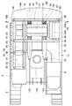
11は上部旋回体3のベースとなる主フレームとしての旋回フレームで、該旋回フレーム11は、図2ないし図4に示すように、後述のセンタフレーム12、左,右のサイドフレーム13,14等により強固な支持構造体として構成されている。そして、旋回フレーム11の前部側には作業装置4が俯仰動可能に取付けられ、旋回フレーム11上には、後述のカウンタウエイト19、エンジン21、熱交換装置24、作動油タンク26、燃料タンク27を含む各種機器(搭載機器)が搭載されるものである。
12は旋回フレーム11の中央部を構成するセンタフレームで、該センタフレーム12は、厚肉な鋼板等により形成され前,後方向に延びる底板12Aと、該底板12A上に立設されて前,後方向に延び、前側から後側に向けて徐々に高さ寸法が小さくなるように形成された左縦板12Bおよび右縦板12Cとにより大略構成されている。
13はセンタフレーム12の左側に位置して前,後方向に延びた左サイドフレーム、14はセンタフレーム12の右側に位置して前,後方向に延びた右サイドフレームで、これら左,右のサイドフレーム13,14は、図3に示すように略D型の断面形状を有する筒体により構成されている。そして、センタフレーム12と左サイドフレーム13との間は、左,右方向に延びる複数(1個のみ図示)の左張出しビーム15によって連結され、センタフレーム12と右サイドフレーム14との間は、左,右方向に延びる複数(1個のみ図示)の右張出しビーム16によって連結されている。
17,17,…はセンタフレーム12の後部側に設けられた複数の下側ブラケットで、該各下側ブラケット17は、図3および図4に示すように、左,右の縦板12B,12C上にそれぞれ前,後方向に離間して2個ずつ配置され、溶接等の手段を用いて固着されている。そして、各下側ブラケット17には、ゴム等の弾性体を有するエンジンマウント18がボルト等(図示せず)を用いてそれぞれ取付けられている。
.. Are a plurality of lower brackets provided on the rear side of the
19は旋回フレーム11の後端部に設けられたカウンタウエイトで、該カウンタウエイト19は、センタフレーム12を構成する左,右の縦板12B,12Cの後端部にボルト20を用いて取付けられ、作業装置4との重量バランスをとるものである。そして、カウンタウエイト19の上部前端側には、その上面19Aよりも一段低い平坦面となって左,右方向に延びる上部フレーム取付面19Bが形成され、この上部フレーム取付面19Bには、後述する上部フレーム31が取付けられる構成となっている。
21はカウンタウエイト19よりも前側に位置して旋回フレーム11上に設けられたエンジンで、該エンジン21は、センタフレーム12の左,右の縦板12B,12Cに設けられた各下側ブラケット17上にエンジンマウント18を介して防振状態に支持され、左,右方向に延在する横置き状態に配置されている。また、図3および図4に示すように、エンジン21の上部側には、後述の各フレーム側ブラケット34に取付けられる4個のエンジン側ブラケット21A,21A,…が設けられている。
An
そして、エンジン21の右側には油圧ポンプ22が設けられ、該油圧ポンプ22は、エンジン21によって駆動されることにより、油圧ショベル1に搭載された各種の油圧アクチュエータに作動用の圧油を供給するものである。一方、エンジン21の左側には冷却ファン23が設けられ、該冷却ファン23は、エンジン21によって駆動されることにより建屋カバー6内に冷却風を取込み、この冷却風を後述の熱交換装置24に供給するものである。
A
24は冷却ファン23の左側に隣接して設けられた熱交換装置で、該熱交換装置24は、エンジン21の冷却水を冷却するラジエータ24A、油圧ショベル1に搭載された各油圧アクチュエータに給排される作動油を冷却するオイルクーラ24B等により構成されている。
A
ここで、ラジエータ24Aは、エンジン21からの冷却水が循環する放熱部を有し、エンジン冷却水の熱を放熱部で熱交換して冷却風中に放熱することにより、エンジン冷却水を冷却するものである。一方、オイルクーラ24Bは、油圧ショベル1の各油圧アクチュエータからの戻り油が流入する放熱部を有し、戻り油の熱を放熱部で熱交換して冷却風中に放熱することにより、作動油を冷却するものである。そして、熱交換装置24の下端部は、旋回フレーム11の左張出しビーム15に複数のボルト25を用いて取付けられ、熱交換装置24の上端部は、後述の上部フレーム31に取付けられる構成となっている。
Here, the
26は油圧ポンプ22の前側に位置して旋回フレーム11の右端側に設けられた作動油タンクで、該作動油タンク26は、油圧ショベル1に搭載された油圧アクチュエータに供給される作動油を貯溜するものである。そして、作動油タンク26の下端部は、旋回フレーム11の右サイドフレーム14、右張出しビーム16にボルト25を用いて取付けられ、作動油タンク26の上端部は、後述の上部フレーム31に取付けられる構成となっている。
A
27は作動油タンク26の前側に位置して旋回フレーム11の右端側に設けられた燃料タンクで、該燃料タンク27は、エンジン21に供給される燃料を貯溜するものである。そして、燃料タンク27の下端部は、旋回フレーム11の右サイドフレーム14、右張出しビーム16にボルト(図示せず)を用いて取付けられ、燃料タンク27の上端部は、後述の上部フレーム31に取付けられる構成となっている。
A
31は旋回フレーム11の上方に設けられた上部フレームで、該上部フレーム31は、上述したカウンタウエイト19、エンジン21、熱交換装置24、作動油タンク26、燃料タンク27を含む各搭載機器の上部側が取付けられることにより、これら各搭載機器を旋回フレーム11との間で上,下方向から挟込んで支持するものである。
ここで、上部フレーム31は、図5等に示すように、複数本の梁材を用いて大きな剛性を有する略L字状の枠体として形成され、後述の後枠部32、前枠部33、各フレーム側ブラケット34等により構成されている。
Here, as shown in FIG. 5 and the like, the
32は上部フレーム31の後部側を構成する後枠部で、該後枠部32は、互いに平行して左,右方向に延びる前横梁32A,後横梁32Bと、これら前横梁32A,後横梁32B間を連結し前,後方向に延びる左縦梁32C、右縦梁32D、中縦梁32Eとにより、全体として左,右方向に延びる長方形の枠状に形成されている。そして、前横梁32A、後横梁32B、左縦梁32Cには、それぞれ後述のボルト35が挿通されるボルト挿通孔32F,32F,…が穿設されている。
33は上部フレーム31の前部側を構成する前枠部で、該前枠部33は、互いに平行して前,後方向に延びる左縦梁33A,右縦梁33Bと、これら左縦梁33A,右縦梁33B間を連結し左,右方向に延びる前横梁33C,後横梁33Dとにより、全体として前,後方向に延びる長方形の枠状に形成されている。そして、左縦梁33Aおよび右縦梁33Bには、それぞれ後述のボルト35が挿通されるボルト挿通孔33E,33E,…が穿設されている。
34,34,…は後枠部32の下面側に設けられた4個のフレーム側ブラケットで、これら各フレーム側ブラケット34は、後枠部32を構成する前横梁32A,後横梁32Bの下面側にそれぞれ2個ずつ溶接等の手段を用いて固着され、エンジン21に設けられた各エンジン側ブラケット21Aに向けて延びている。
34, 34,... Are four frame side brackets provided on the lower surface side of the
そして、図2ないし図4に示すように、上部フレーム31を構成する後枠部32の後横梁32Bは、カウンタウエイト19の上部フレーム取付面19Bにボルト35を用いて取付けられ、後枠部32の各フレーム側ブラケット34は、エンジン21の各エンジン側ブラケット21Aに後述の防振装置36を介して取付けられ、後枠部32の左縦梁32Cは、熱交換装置24の上面にボルト35を用いて取付けられる構成となっている。
As shown in FIGS. 2 to 4, the rear
また、上部フレーム31を構成する前枠部33の左,右の縦梁33A,33Bと後枠部32の前横梁32Aとは、作動油タンク26の上面にボルト35を用いて取付けられ、前枠部33の左,右の縦梁33A,33Bは、燃料タンク27の上面にボルト35を用いて取付けられる構成となっている。
The left and right
このように、旋回フレーム11に搭載されたカウンタウエイト19、エンジン21、熱交換装置24、作動油タンク26、燃料タンク27等の各搭載機器を、旋回フレーム11と上部フレーム31との間で挟込んで支持することにより、これら各搭載機器の上部側を拘束し、油圧ショベル1の稼動時に発生した振動によって各搭載機器の上部側が大きく振動するのを抑えることができる構成となっている。また、上部フレーム31は、エンジン21、熱交換装置24、作動油タンク26、燃料タンク27等と共に、建屋カバー6内に収容される構成となっている。
As described above, the mounted devices such as the
36は各搭載機器のうちエンジン21と上部フレーム31との間に設けられた防振装置で、該各防振装置36は、図6に示すように、ゴム等の弾性材料を用いて角柱状に形成された弾性体36Aと、該弾性体36Aに固着された一対のフランジ板36B,36Cとにより構成されている。また、一方のフランジ板36Bはエンジン21のエンジン側ブラケット21Aに固定され、他方のフランジ板36Cは上部フレーム31のフレーム側ブラケット34にボルト35を用いて固定されている。
36 is an anti-vibration device provided between the
そして、エンジン21と上部フレーム31との間に設けられた防振装置36は、エンジン21がその作動時に発生する比較的高い周波数の振動を弾性体36Aの弾性変形によって吸収することにより、エンジン21の振動による騒音を低減すると共に、キャブ5内に乗込んだオペレータの乗り心地を向上するものである。
The
本実施の形態による油圧ショベル1は上述の如き構成を有するもので、この油圧ショベル1は、下部走行体2によって作業現場まで自走した後、上部旋回体3を旋回させつつ作業装置4を用いて土砂等の掘削作業を行う。
The hydraulic excavator 1 according to the present embodiment has the above-described configuration. The hydraulic excavator 1 uses the working device 4 while turning the upper swinging body 3 after the
ここで、油圧ショベル1が不整地等を走行する場合には、カウンタウエイト19は、左,右方向(車幅方向)に延びる軸線を中心とした前,後方向への振動(ピッチング振動)、あるいは前,後方向(車長方向)に延びる軸線を中心とした左,右方向への振動(ローリング振動)を発生する。
Here, when the excavator 1 travels on rough terrain or the like, the
また、掘削作業時に作業装置4を俯仰動させた場合、作業装置4による掘削作業時に下部走行体2の後部が上方に持上がった後に急激に地面に接地する場合、作業装置4を地面に押付けて下部走行体2の前部側を持上げるジャッキアップ動作を行なった後、このジャッキアップ動作を解除して下部走行体2の前部側を地面に下した場合等においても、カウンタウエイトはピッチング振動、ローリング振動等を発生する。
Further, when the working device 4 is moved up and down during excavation work, when the rear portion of the
このように、油圧ショベル1の稼動時にカウンタウエイト19がピッチング振動、ローリング振動等を発生すると、この振動は旋回フレーム11から該旋回フレーム11に搭載されたエンジン21、熱交換装置24、作動油タンク26、燃料タンク27等に伝わるようになる。
As described above, when the
しかし、本実施の形態では、下部側が旋回フレーム11に取付けられたカウンタウエイト19、エンジン21、熱交換装置24、作動油タンク26、燃料タンク27等の各搭載機器の上部側を、旋回フレーム11の上方に配置した上部フレーム31に取付けることにより、これら各搭載機器を旋回フレーム11と上部フレーム31とによって上,下方向から挟込んで支持する構成としたので、各搭載機器の上部側を上部フレーム31によって拘束することができる。
However, in the present embodiment, the upper side of each mounted device such as the
従って、油圧ショベル1の稼動時に発生した振動が、旋回フレーム11からカウンタウエイト19、エンジン21、熱交換装置24、作動油タンク26、燃料タンク27等の各搭載機器に伝わったとしても、これら各搭載機器の上部側が大きく振動するのを抑えることができる。この結果、カウンタウエイト19、エンジン21、熱交換装置24、作動油タンク26、燃料タンク27等の各搭載機器と旋回フレーム11との取付部に作用する負荷を低減してその耐久性を高めることができ、かつ各搭載機器自体の耐久性を高めることができる。
Therefore, even if the vibration generated during the operation of the hydraulic excavator 1 is transmitted from the
また、エンジン21と上部フレーム31との間に防振装置36を設けることにより、エンジン21がその作動時に発生する比較的高い周波数の振動を、弾性体36Aの弾性変形によって吸収することができ、エンジン21の振動による騒音を低減すると共に、キャブ5内に乗込んだオペレータの乗り心地を向上することができる。
In addition, by providing the
次に、図7は本発明の第2の実施の形態を示し、本実施の形態の特徴は、上部フレームを分割可能な複数個の上部フレーム分割体によって構成したことにある。なお、本実施の形態では、上述した第1の実施の形態と同一の構成要素に同一符号を付し、その説明を省略するものとする。 Next, FIG. 7 shows a second embodiment of the present invention. The feature of this embodiment is that the upper frame is constituted by a plurality of upper frame divided bodies. In the present embodiment, the same components as those in the first embodiment described above are denoted by the same reference numerals, and the description thereof is omitted.
図中、41は第1の実施の形態による上部フレーム31に代えて本実施の形態に用いた上部フレームで、該上部フレーム41は、後述する後側上部フレーム分割体42と、前側上部フレーム分割体44とにより構成されている。
In the figure,
42は後述の前側上部フレーム分割体44と共に上部フレーム41を構成する後側上部フレーム分割体で、該後側上部フレーム分割体42は、互いに平行して左,右方向に延びる前横梁42A,後横梁42Bと、これら前横梁42A,後横梁42B間を連結し前,後方向に延びる左縦梁42C、右縦梁42D、中縦梁42Eとにより、全体として左,右方向に延びる長方形の枠状に形成されている。
ここで、前横梁42Aと右縦梁42Dとが交わる部位には、後述の係合凸部44Fが係合する四角形状の凹陥部42Fが形成され、前横梁42Aと中縦梁42Eとが交わる部位には、後述の係合凸部44Eが係合する四角形状の凹陥部42Gが形成されている。また、これら各凹陥部42F,42G、後横梁42B、左縦梁42Cには、それぞれボルト35が挿通されるボルト挿通孔42H,42H,…が穿設されている。
Here, a quadrangular recessed
43,43,…は後側上部フレーム分割体42の下面側に設けられた4個のフレーム側ブラケットで、これら各フレーム側ブラケット43は、前横梁42A,後横梁42Bの下面側にそれぞれ2個ずつ溶接等の手段を用いて固着されている。そして、これら各フレーム側ブラケット43は、エンジンに設けられた各エンジン側ブラケット(いずれも図示せず)に取付けられるものである。
43 are four frame side brackets provided on the lower surface side of the rear upper frame divided
44は前側上部フレーム分割体で、該前側上部フレーム分割体44は、互いに平行して前,後方向に延びる左縦梁44A,右縦梁44Bと、これら左縦梁44A,右縦梁44B間を連結し左,右方向に延びる前横梁44C,後横梁44Dとにより、全体として前,後方向に延びる長方形の枠状に形成されている。
ここで、左縦梁44Aの後端部には、後側上部フレーム分割体42の凹陥部42Gに係合する四角形状の係合凸部44Eが形成され、右縦梁44Bの後端部には、後側上部フレーム分割体42の凹陥部42Fに係合する四角形状の係合凸部44Fが形成されている。また、これら各係合凸部44E,44F、左縦梁44A、右縦梁44Bには、それぞれボルト35が挿通されるボルト挿通孔44G,44G,…が穿設されている。
Here, at the rear end portion of the left
そして、後側上部フレーム分割体42に形成された各凹陥部42F,42Gに、前側上部フレーム分割体44に形成された各係合凸部44E,44Fを係合させることにより、後側上部フレーム分割体42と前側上部フレーム分割体44とからなる分割可能な上部フレーム41が構成されている。
Then, by engaging the engaging
本実施の形態による油圧ショベルは上述の如き分割可能な上部フレーム41を有するもので、その基本的作動については、上述した第1の実施の形態によるものと格別差異はない。
The hydraulic excavator according to the present embodiment has the splittable
然るに、本実施の形態によれば、旋回フレーム11と上部フレーム41との間に挟込まれた各搭載機器に対する点検作業等を行う場合に、上部フレーム41を後側上部フレーム分割体42と前側上部フレーム分割体44とに分割することができる。これにより、後側上部フレーム分割体42と前側上部フレーム分割体44のうち、点検すべき搭載機器に取付けられた分割体のみを容易に取外すことができるので、各搭載機器を旋回フレーム11と上部フレーム41との間で挟込んで支持した状態でも、各搭載機器に対する点検作業を容易に行なうことができる。
However, according to the present embodiment, when performing an inspection operation or the like on each mounted device sandwiched between the turning
次に、図8および図9は本発明の第3の実施の形態を示し、本実施の形態の特徴は、上部フレームと各搭載機器との間に防振装置を設ける構成としたことにある。なお、本実施の形態では、上述した第1の実施の形態と同一の構成要素に同一符号を付し、その説明を省略するものとする。 Next, FIG. 8 and FIG. 9 show a third embodiment of the present invention, and the feature of this embodiment is that a vibration isolator is provided between the upper frame and each mounted device. . In the present embodiment, the same components as those in the first embodiment described above are denoted by the same reference numerals, and the description thereof is omitted.
51,51,…はカウンタウエイト19、熱交換装置24、作動油タンク26、燃料タンク27等の各搭載機器と上部フレーム31との間に設けられた防振装置で、該各防振装置51は、例えばゴム等の弾性体を用いて形成されている。そして、防振装置51は、カウンタウエイト19と上部フレーム31との間、熱交換装置24と上部フレーム31との間、作動油タンク26と上部フレーム31との間、燃料タンク27と上部フレーム31との間に、それぞれボルト35を用いて取付けられている。
, 51 are vibration isolators provided between the
ここで、防振装置51は、例えば油圧ショベルの走行時、掘削作業時等において旋回フレーム11が比較的高い周波数の振動を発生したときに、弾性体が変形することによってこの振動を吸収するものである。これにより、旋回フレーム11に取付けられたカウンタウエイト19、熱交換装置24、作動油タンク26、燃料タンク27等の各搭載機器が、旋回フレーム11が発生した高い周波数の振動に共振するのを抑えることができる構成となっている。
Here, the
本実施の形態による油圧ショベルは上述の如き構成を有するもので、その基本的作動については、上述した第1の実施の形態によるものと格別差異はない。 The hydraulic excavator according to the present embodiment has the above-described configuration, and the basic operation thereof is not particularly different from that according to the first embodiment described above.
然るに、本実施の形態によれば、カウンタウエイト19、熱交換装置24、作動油タンク26、燃料タンク27等の各搭載機器と上部フレーム31との間に防振装置51を設ける構成としたので、例えば油圧ショベルの走行時、掘削作業時等において旋回フレーム11が比較的高い周波数の振動を発生したとしても、各搭載機器が旋回フレーム11の振動に共振するのを防振装置51によって抑えることができる。これにより、カウンタウエイト19、熱交換装置24、作動油タンク26、燃料タンク27等が、旋回フレーム11が発生した高い周波数の振動に共振して破損するのを抑え、これら各搭載機器の耐久性を高めることができる。
However, according to the present embodiment, the
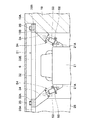
次に、図10ないし図14は本発明の第4の実施の形態を示し、本実施の形態の特徴は、上部フレームと主フレームとの間を上,下方向で連結する縦連結材を設ける構成としたことにある。なお、本実施の形態では、上述した第1の実施の形態と同一の構成要素に同一符号を付し、その説明を省略するものとする。 Next, FIGS. 10 to 14 show a fourth embodiment of the present invention. The feature of the present embodiment is that a vertical connecting member for connecting the upper frame and the main frame in the upward and downward directions is provided. It is in the configuration. In the present embodiment, the same components as those in the first embodiment described above are denoted by the same reference numerals, and the description thereof is omitted.
図中、61は第1の実施の形態による上部フレーム31に代えて本実施の形態に用いた上部フレームで、該上部フレーム61は、図13及び図14等に示すように、複数本の梁材を用いて大きな剛性を有する枠体として形成され、後述の後枠部62、前枠部63、各フレーム側ブラケット64等により構成されている。
In the figure,
62は上部フレーム61の後部側を構成する後枠部で、該後枠部62は、互いに平行に左,右方向に延びる前横梁62A,中横梁62B,後横梁62Cと、中横梁62Bと後横梁62Cとの間を連結し前,後方向に延びる左縦梁62D,前横梁62Aと後横梁62Cとの間を連結し前,後方向に延びる右縦梁62Eと、これら左,右の縦梁62D,62E間に位置して前,後に延び、後述の左縦板66が取付けられる左縦板取付梁62F,右縦板67が取付けられる右縦板取付梁62Gとにより、全体として左,右方向に延びるほぼ長方形の枠状に形成されている。
ここで、右縦梁62Eの後端部は後横梁62Cに固着され、右縦梁62Eの前部側は、前横梁62Aから前方へと延び、後述する前枠部63の一部を構成している。また、左縦板取付梁62Fと右縦板取付梁62Gとは、その後端部が後横梁62Cに固着され、前部側は中横梁62Bから前方へと延びている。
Here, the rear end portion of the right
そして、図10及び図11に示すように、左縦板取付梁62Fは、旋回フレーム11を構成する左縦板12Bと上,下方向で対向し、右縦板取付梁62Gは、右縦板12Cと上,下方向で対向する構成となっている。さらに、後枠部62を構成する前横梁62A、中横梁62B、後横梁62C、左縦梁62D、右縦梁62Eには、それぞれ後述のボルト65が挿通されるボルト挿通孔62H,62H,…が穿設されている。
10 and 11, the left vertical
63は後枠部62の右前側に配置され上部フレーム61の前部側を構成する前枠部で、該前枠部63は、後枠部62の前横梁62Aと平行に左,右方向に延びる前横梁63Aと、この前横梁63Aと後枠部62の前横梁62Aとの間を連結し前,後方向に延びる左縦梁63Bと、後枠部62の右縦梁62Eに一体形成され左縦梁63Bと平行に前,後方向に延びる右縦梁63CとによりU字状に形成されている。
そして、前枠部63を構成する左縦梁63B、右縦梁63Cには、それぞれ後述のボルト65が挿通されるボルト挿通孔63D,63D,…が穿設されている。なお、本実施の形態では、後枠部62の右縦梁62Eと前枠部63の右縦梁63Cとを一体形成した場合を例示しているが、これら右縦梁62Eと右縦梁63Cとは別部材によって構成してもよいものである。
Further, in the left
64,64,…は後枠部62の下面側に設けられた4個のフレーム側ブラケットで、これら各フレーム側ブラケット64は、後枠部62を構成する中横梁62B,後横梁62Cの下面側にそれぞれ2個ずつ溶接等の手段を用いて固着され、図11及び図12に示すように、エンジン21に設けられた各エンジン側ブラケット21Aに向けて延びている。
64, 64,... Are four frame side brackets provided on the lower surface side of the
そして、図10ないし図12に示すように、後枠部62の後横梁62Cは、カウンタウエイト19の上部フレーム取付面19Bにボルト65を用いて取付けられ、後枠部62の各フレーム側ブラケット64は、エンジン21の各エンジン側ブラケット21Aに防振装置36を介して取付けられ、後枠部62の左縦梁62Dは、熱交換装置24の上面にボルト65を用いて取付けられる構成となっている。
10 to 12, the
また、後枠部62の前横梁62A、中横梁62B、右縦梁62Eは、作動油タンク26の上面にボルト65を用いて取付けられ、前枠部63の左縦梁63Bと右縦梁63Cとは、燃料タンク27の上面にボルト65を用いて取付けられる構成となっている。
The front
66は上部フレーム61と旋回フレーム11との間に設けられた縦連結材としての左縦板で、該左縦板66は、上部フレーム61の左縦板取付梁62Fと旋回フレーム11との間を上,下方向で連結するものである。
66 is a left vertical plate as a vertical connecting member provided between the
67は上部フレーム61と旋回フレーム11との間に設けられた縦連結材としての右縦板で、該右縦板67は、上部フレーム61の右縦板取付梁62Gと旋回フレーム11との間を上,下方向で連結するものである。
67 is a right vertical plate as a vertical connecting member provided between the
ここで、左縦板66は、図12及び図13等に示すように、例えば厚肉な鋼板材等を用いて略長方形の平板状に形成され、前,後方向の中間部から後部までの範囲には、下端側が開口端となって上,下方向に延びる開口部66Aが設けられている。また、左縦板66の下端側には、図11に示すように、旋回フレーム11の左縦板12Bに当接する直方体状のスペーサ66Bが突設されると共に、後述のボルト68が挿通される複数のボルト挿通孔66Cが穿設されている。
Here, as shown in FIGS. 12 and 13, etc., the left
一方、右縦板67も左縦板66と同様に、開口部67Aが設けられた略長方形の平板状に形成され、右縦板67の下端側には、スペーサ67Bが突設されると共に複数のボルト挿通孔67Cが穿設されている。
On the other hand, like the left
そして、左縦板66の上端側は、図14等に示すように上部フレーム61の左縦板取付梁62Fに溶接等の手段を用いて固着され、左縦板66の下端側は、図11等に示すように旋回フレーム11の左縦板12Bにスペーサ66Bを当接させた状態で当該左縦板12Bにボルト68を用いて固定され、左縦板66の開口部66A内にはエンジン21が配置される構成となっている。
The upper end side of the left
一方、右縦板67の上端側は、上部フレーム61の右縦板取付梁62Gに溶接等の手段を用いて固着され、右縦板67の下端側は、旋回フレーム11の右縦板12Cにスペーサ67Bを当接させた状態で当該右縦板12Cにボルト68を用いて固定され、右縦板67の開口部67A内にはエンジン21が配置される構成となっている。
On the other hand, the upper end side of the right
このように、本実施の形態では、カウンタウエイト19、エンジン21、熱交換装置24、作動油タンク26、燃料タンク27等の各搭載機器が搭載された旋回フレーム11と、各搭載機器の上部側が取付けられた上部フレーム61との間を、左縦板66及び右縦板67を用いて上,下方向で連結する構成となっている。
As described above, in the present embodiment, the revolving
本実施の形態は上述の如き構成を有するもので、旋回フレーム11に搭載された複数の搭載機器の上部側を上部フレーム61に取付けることにより、これら各搭載機器の上部側を上部フレーム61によって拘束することができる上に、上部フレーム61と旋回フレーム11との間を左縦板66及び右縦板67を用いて連結することにより、上部フレーム61が旋回フレーム11に対して大きく変位(振動)するのを抑えることができる。
The present embodiment has the above-described configuration. By attaching the upper side of a plurality of mounted devices mounted on the turning
この結果、上部フレーム61に上部側が取付けられたカウンタウエイト19、エンジン21、熱交換装置24、作動油タンク26、燃料タンク27等の各搭載機器と旋回フレーム11との取付部に作用する負荷を一層低減することができるので、各搭載機器と旋回フレーム11との取付部の耐久性、各搭載機器自体の耐久性を一層高めることができる。
As a result, the load acting on the mounting portion between the
なお、上述した第1の実施の形態では、旋回フレーム11に搭載されたカウンタウエイト19、エンジン21、熱交換装置24、作動油タンク26、燃料タンク27の5つの搭載機器を旋回フレーム11と上部フレーム31との間で挟込んで支持した場合を例示している。しかし、本発明はこれに限らず、これら各搭載機器のうち振動を抑制したい少なくとも2つの搭載機器を、旋回フレーム11と上部フレーム31との間で挟込んで支持することにより、これら少なくとも2つの搭載機器の上部側を上部フレーム31によって拘束すればよいものである。
In the first embodiment described above, the five mounted devices of the
即ち、例えば図15に示す変形例のように、旋回フレーム11に搭載された各搭載機器のうちカウンタウエイト19、エンジン21、熱交換装置24の3つの搭載機器を、旋回フレーム11と上部フレーム31′との間で挟込んで支持することにより、これらカウンタウエイト19、エンジン21、熱交換装置24の上部側を上部フレーム31′によって拘束してもよい。
That is, for example, as in the modification shown in FIG. 15, among the mounted devices mounted on the
また、例えば図16に示す他の変形例のように、旋回フレーム11に搭載された各搭載機器のうち作動油タンク26と燃料タンク27との2つの搭載機器を、旋回フレーム11と上部フレーム31″との間で挟込んで支持することにより、これら作動油タンク26、燃料タンク27の上部側を上部フレーム31″によって拘束してもよい。
Further, for example, as in another modification shown in FIG. 16, two mounted devices, that is, the
また、上述した第1の実施の形態では、エンジン21と上部フレーム31との間にゴム等の弾性材料からなる弾性体36Aを有する防振装置36を設けた場合を例示している。しかし、本発明はこれに限らず、例えば図17に示す変形例のように、エンジン21と上部フレーム31との間にばね52とオイルダンパ53とにより構成された防振装置54を設ける構成としてもよい。
In the first embodiment described above, the case where the
また、上述した第4の実施の形態では、上部フレーム61の各フレーム側ブラケット64とエンジン21との間にのみ防振装置36を設けた場合を例示している。しかし、本発明はこれに限るものではなく、例えば図18に示す変形例のように、上部フレーム61とカウンタウエイト、熱交換装置24、作動油タンク26、燃料タンク等の各搭載機器との間に、例えばゴム等の弾性体を用いて形成された防振装置69を設ける構成としてもよい。
Further, in the above-described fourth embodiment, the case where the
また、上述した第4の実施の形態では、旋回フレーム11に搭載されたカウンタウエイト19、エンジン21、熱交換装置24、作動油タンク26、燃料タンク27の5つの搭載機器の上部側を上部フレーム61に取付けた場合を例示している。しかし、本発明はこれに限らず、これら各搭載機器のうちいずれか2つ以上の搭載機器の上部側を上部フレーム61に取付ける構成としてもよい。
Further, in the above-described fourth embodiment, the upper frame of the five mounted devices, that is, the
また、上述した第4の実施の形態では、上部フレーム61と旋回フレーム11との間を、左縦板66と右縦板67とからなる2つの縦連結材を用いて連結した場合を例示している。しかし、本発明はこれに限らず、例えば1つまたは3つ以上の縦連結材を用いて上部フレーム61と旋回フレーム11との間を連結する構成としてもよい。
Further, in the above-described fourth embodiment, the case where the
また、上述した第4の実施の形態では、左縦板66、右縦板67の上端側をそれぞれ上部フレーム61に溶接等によって固着し、下端側をボルト65を用いて旋回フレーム11に取付ける場合を例示している。しかし、本発明はこれに限らず、例えば左縦板66、右縦板67の上端側をそれぞれボルトを用いて上部フレーム61に取付け、下端側をボルト65を用いて旋回フレーム11に取付ける構成としてもよい。
In the above-described fourth embodiment, the upper ends of the left
さらに、上述した第4の実施の形態では、上部フレーム61を後枠部62と前枠部63とからなる一体物として構成した場合を例示している。しかし、本発明はこれに限らず、2以上の上部フレーム分割体によって構成される上部フレームを用いてもよい。
Furthermore, in the above-described fourth embodiment, the case where the
また、上述した各実施の本実施の形態では、旋回フレーム11に搭載される搭載機器として、カウンタウエイト19、エンジン21、熱交換装置24、作動油タンク26、燃料タンク27を例示している。しかし、本発明はこれに限らず、例えば油圧ポンプ22から各種の油圧アクチュエータに給排される圧油の方向を制御する制御弁ユニット、バッテリ(いずれも図示せず)等の他の機器類も、旋回フレーム11に搭載される搭載機器に含まれるものである。
Further, in each of the embodiments described above, the
また、上述した第2の実施の形態では、上部フレーム41を後側上部フレーム分割体42と前側上部フレーム分割体44との2個のフレーム分割体によって構成した場合を例示している。しかし、本発明はこれに限らず、例えば3個以上のフレーム分割体によって上部フレームを構成してもよい。
In the second embodiment described above, the case where the
さらに、上述した各実施の形態では、作業機械として油圧ショベルを例示している。しかし、本発明はこれに限らず、例えば油圧クレーン、ホイールローダ等の他の建設機械、リフトトラック等の作業機械にも広く適用することができる。 Furthermore, in each embodiment mentioned above, the hydraulic excavator is illustrated as a working machine. However, the present invention is not limited to this, and can be widely applied to other construction machines such as hydraulic cranes and wheel loaders, and work machines such as lift trucks.
11 旋回フレーム(主フレーム)
19 カウンタウエイト(搭載機器)
21 エンジン(搭載機器)
24 熱交換装置(搭載機器)
26 作動油タンク(搭載機器)
27 燃料タンク(搭載機器)
31,31′,31″,41,61 上部フレーム
36,51,54,69 防振装置
42 後側上部フレーム分割体(上部フレーム分割体)
44 前側上部フレーム分割体(上部フレーム分割体)
66 左縦板(縦連結材)
67 右縦板(縦連結材)
11 Rotating frame (main frame)
19 Counterweight (equipped equipment)
21 Engine (equipped equipment)
24 Heat exchange device (equipment)
26 Hydraulic oil tank (equipped equipment)
27 Fuel tank (equipped equipment)
31, 31 ', 31 ", 41, 61
44 Front upper frame division (upper frame division)
66 Left vertical plate (vertical connecting material)
67 Right vertical plate (vertical connecting material)
Claims (4)
前記各搭載機器のうち少なくとも2つの搭載機器の上部側を支持する上部フレームを設ける構成としたことを特徴とする作業機械。 In a work machine comprising a main frame which is provided with a work structure and a work structure, and a mounted equipment including a counterweight, an engine, a heat exchange device, a fuel tank, and a hydraulic oil tank mounted on the main frame,
A working machine comprising an upper frame that supports upper sides of at least two mounted devices among the mounted devices.
Priority Applications (1)
| Application Number | Priority Date | Filing Date | Title |
|---|---|---|---|
| JP2005300590A JP2006298355A (en) | 2005-03-24 | 2005-10-14 | Working machine |
Applications Claiming Priority (2)
| Application Number | Priority Date | Filing Date | Title |
|---|---|---|---|
| JP2005086630 | 2005-03-24 | ||
| JP2005300590A JP2006298355A (en) | 2005-03-24 | 2005-10-14 | Working machine |
Publications (1)
| Publication Number | Publication Date |
|---|---|
| JP2006298355A true JP2006298355A (en) | 2006-11-02 |
Family
ID=37466915
Family Applications (1)
| Application Number | Title | Priority Date | Filing Date |
|---|---|---|---|
| JP2005300590A Pending JP2006298355A (en) | 2005-03-24 | 2005-10-14 | Working machine |
Country Status (1)
| Country | Link |
|---|---|
| JP (1) | JP2006298355A (en) |
Cited By (3)
| Publication number | Priority date | Publication date | Assignee | Title |
|---|---|---|---|---|
| EP2177670A1 (en) * | 2008-10-17 | 2010-04-21 | Liebherr-Hydraulikbagger GmbH | Superstructure for a movable work device |
| EP2428618A1 (en) * | 2010-09-14 | 2012-03-14 | Kobelco Construction Machinery Co., Ltd. | Device removing/re-inserting structure, and device removing/re-inserting method for construction machine |
| CN110656674A (en) * | 2019-11-05 | 2020-01-07 | 三一重机有限公司 | Excavator rotating platform and excavator |
Citations (2)
| Publication number | Priority date | Publication date | Assignee | Title |
|---|---|---|---|---|
| JPH1016572A (en) * | 1996-07-01 | 1998-01-20 | Ishikawajima Constr Mach Co | Engine supporting structure of working vehicle |
| JPH11269921A (en) * | 1998-03-23 | 1999-10-05 | Kubota Corp | Revolving working machine |
-
2005
- 2005-10-14 JP JP2005300590A patent/JP2006298355A/en active Pending
Patent Citations (2)
| Publication number | Priority date | Publication date | Assignee | Title |
|---|---|---|---|---|
| JPH1016572A (en) * | 1996-07-01 | 1998-01-20 | Ishikawajima Constr Mach Co | Engine supporting structure of working vehicle |
| JPH11269921A (en) * | 1998-03-23 | 1999-10-05 | Kubota Corp | Revolving working machine |
Cited By (6)
| Publication number | Priority date | Publication date | Assignee | Title |
|---|---|---|---|---|
| EP2177670A1 (en) * | 2008-10-17 | 2010-04-21 | Liebherr-Hydraulikbagger GmbH | Superstructure for a movable work device |
| US8177017B2 (en) | 2008-10-17 | 2012-05-15 | Liebherr-Hydraulikbagger Gmbh | Traveling working machine |
| EP2573280A3 (en) * | 2008-10-17 | 2014-05-14 | Liebherr-Hydraulikbagger GmbH | Base steel plate of the suprestructure of a mobile works machine |
| EP2428618A1 (en) * | 2010-09-14 | 2012-03-14 | Kobelco Construction Machinery Co., Ltd. | Device removing/re-inserting structure, and device removing/re-inserting method for construction machine |
| US8382198B2 (en) | 2010-09-14 | 2013-02-26 | Kobelco Construction Machinery Co., Ltd. | Device removing/re-inserting structure, and device removing/re-inserting method for construction machine |
| CN110656674A (en) * | 2019-11-05 | 2020-01-07 | 三一重机有限公司 | Excavator rotating platform and excavator |
Similar Documents
| Publication | Publication Date | Title |
|---|---|---|
| JP5666234B2 (en) | Construction machinery | |
| JP2006328764A (en) | Turning frame of construction machinery | |
| JP2015040397A (en) | Construction machine | |
| JP2006335329A (en) | Cooling device of working vehicle | |
| JP5411173B2 (en) | Construction machine swivel frame | |
| JP2010007368A (en) | Construction machinery | |
| JP2006298355A (en) | Working machine | |
| JP5541709B2 (en) | Construction machinery | |
| JP2007120221A (en) | Construction machine | |
| JP4276151B2 (en) | Construction machinery | |
| JP5077410B2 (en) | Strut mounting structure of a construction machine | |
| JP4851603B2 (en) | Construction machinery | |
| JP4611844B2 (en) | Construction machinery | |
| JP2005344394A (en) | Construction equipment | |
| JP4199173B2 (en) | Swivel construction machine | |
| JP4256230B2 (en) | Construction machinery | |
| JP6557019B2 (en) | Construction machinery | |
| JP2008230314A (en) | Backhoe | |
| JP2005083019A (en) | Construction machine | |
| JP4885787B2 (en) | Construction machinery | |
| KR20080093582A (en) | Upper frame of excavator of having reinforcement member beam type | |
| JP2005336829A (en) | Revolving frame for construction machine | |
| JP2000136545A (en) | Cab-equipped construction machine | |
| JP5073045B2 (en) | Construction machinery | |
| JP2003026040A (en) | Framed tractor body and composite working vehicle |
Legal Events
| Date | Code | Title | Description |
|---|---|---|---|
| A621 | Written request for application examination |
Effective date: 20071120 Free format text: JAPANESE INTERMEDIATE CODE: A621 |
|
| A977 | Report on retrieval |
Free format text: JAPANESE INTERMEDIATE CODE: A971007 Effective date: 20100330 |
|
| A131 | Notification of reasons for refusal |
Effective date: 20100406 Free format text: JAPANESE INTERMEDIATE CODE: A131 |
|
| A02 | Decision of refusal |
Effective date: 20100831 Free format text: JAPANESE INTERMEDIATE CODE: A02 |