JP2006281908A - Pneumatic tire - Google Patents
Pneumatic tire Download PDFInfo
- Publication number
- JP2006281908A JP2006281908A JP2005102390A JP2005102390A JP2006281908A JP 2006281908 A JP2006281908 A JP 2006281908A JP 2005102390 A JP2005102390 A JP 2005102390A JP 2005102390 A JP2005102390 A JP 2005102390A JP 2006281908 A JP2006281908 A JP 2006281908A
- Authority
- JP
- Japan
- Prior art keywords
- tire
- lug
- buffer portion
- less
- tread
- Prior art date
- Legal status (The legal status is an assumption and is not a legal conclusion. Google has not performed a legal analysis and makes no representation as to the accuracy of the status listed.)
- Pending
Links
Images


Abstract
Description
本発明は、トラクタ等の農業機械に主として装着される空気入りタイヤに関する。 The present invention relates to a pneumatic tire mainly mounted on an agricultural machine such as a tractor.
トラクタ等の農業機械には、牽引力、排土性等の観点からラグ付きのタイヤが用いられる。ラグは、タイヤ赤道近傍からトレッドの端に向かって、斜めに延びている。トレッドには、左側のラグと右側のラグとが、回転方向において交互に配置されている。隣接するラグ同士の間には、ギャップが存在する。ギャップの深さは、乗用車タイヤの溝の深さに比べて大きい。ギャップの幅は、乗用車タイヤの溝の幅に比べて大きい。トラクタの走行時には、ラグ及びギャップに起因する振動が発生する。 Tires with lugs are used for agricultural machines such as tractors from the viewpoint of traction, soil removal, and the like. The lug extends obliquely from the vicinity of the tire equator toward the end of the tread. In the tread, the left lug and the right lug are alternately arranged in the rotation direction. There is a gap between adjacent lugs. The depth of the gap is larger than the depth of the groove of the passenger car tire. The width of the gap is larger than the width of the groove of the passenger car tire. When the tractor travels, vibrations are generated due to the lugs and gaps.
タイヤの回転に伴い、タイヤと地面との接地箇所は、一方のラグに沿って赤道からトレッドの端に向かって移行する。トレッドの端に至った接地箇所は、他方のラグの赤道へと移行し、さらにこの他方のラグに沿って赤道からトレッドの端に向かって移行する。走行時には、このような接地箇所の移行が繰り返される。この移行は、非連続的である。この移行によっても、トラクタに振動が発生する。 As the tire rotates, the ground contact point between the tire and the ground moves from the equator toward the end of the tread along one lug. The ground contact point that reaches the end of the tread moves to the equator of the other lug, and further moves along the other lug from the equator to the end of the tread. During traveling, such a transition of the ground contact point is repeated. This transition is discontinuous. This transition also causes vibrations in the tractor.
農地間の移動のときには、トラクタはアスファルト舗装された一般道を走行する。この一般道の走行では、振動が特に顕著である。振動は、トラクタの乗り心地を阻害する。トラクタが高性能化しつつある近年、その乗り心地に対する要求が高まりつつある。 When moving between farmland, tractors travel on asphalt paved roads. Vibrations are particularly noticeable on this general road. Vibration impairs the riding comfort of the tractor. In recent years, when the performance of tractors is increasing, the demand for ride comfort is increasing.
ラグとラグとの間にブロック状の突起が設けられることで振動が低減されたタイヤが、提案されている。このブロックは、排土性に悪影響を与える。ブロックはまた、タイヤの質量を高める。 There has been proposed a tire in which vibration is reduced by providing a block-like protrusion between the lugs. This block has an adverse effect on soil removal. The block also increases the mass of the tire.
一方のラグと他方のラグとの間のラップ量が大きく設定されることで振動が低減されたタイヤが、提案されている。この手法では、振動低減は十分ではない。 There has been proposed a tire in which vibration is reduced by setting a large amount of lap between one lug and the other lug. With this method, vibration reduction is not sufficient.
ラグが硬質な外層と軟質な内層とを有することで振動が低減されたタイヤが、提案されている。振動が低減されたタイヤは、乗り心地に優れる。 There has been proposed a tire in which vibration is reduced by having a hard outer layer and a soft inner layer of a lug. A tire with reduced vibration is excellent in ride comfort.
特開2003−267003公報には、面取されたブロックを備えたATVタイヤが開示されている。このタイヤでは、面取によってトラクション性能と旋回性能とが両立されている。
回転方向側に位置するラグの稜は、走行時において路面に先着する。このラグの稜は、路面先着時に大きな衝撃を受ける。特に、一方のラグのトレッドの端に至った接地箇所が他方のラグの赤道へと移行するときに、この衝撃は最大となる。衝撃が大きいタイヤは、振動が大きくなるので乗り心地に劣る。振動が低減されるために軟質な内層が備えられたタイヤでは、走行時に外層が摩滅すると内層が露出する。内層が露出したタイヤは、トラクション性能が低下するので走行性能に劣る。また、複数のゴム層がラグに設けられるタイヤの製造工程は、複雑である。乗り心地と走行性能とに優れたタイヤは、未だ得られていない。 The edge of the lug located on the rotation direction side arrives first on the road surface during traveling. The ridge of this lug receives a big impact when the road surface arrives first. In particular, this impact is greatest when the ground contact point that reaches the end of the tread of one lug moves to the equator of the other lug. A tire with a large impact is inferior in riding comfort because of increased vibration. In a tire provided with a soft inner layer to reduce vibration, the inner layer is exposed when the outer layer is worn away during running. A tire having an exposed inner layer is inferior in running performance because traction performance is reduced. Moreover, the manufacturing process of the tire in which a plurality of rubber layers are provided on the lug is complicated. Tires excellent in ride comfort and running performance have not been obtained yet.
本発明の目的は、乗り心地と走行性能との両方に優れるタイヤの提供にある。 An object of the present invention is to provide a tire excellent in both ride comfort and running performance.
本発明に係るタイヤは、架橋ゴムからなるトレッドを備えている。このトレッドは、赤道近傍からトレッド端近傍まで延びる多数のラグを備えている。これらのラグは、回転方向において左右交互に配置されている。このラグは、赤道近傍から軸方向外側に延びる水平部と、この水平部の端からトレッドの端に向かって回転方向後方に斜めに延びる斜方部とを備えている。この水平部は、その回転方向側に水平前辺部と水平側辺部とを備えている。この水平前辺部は、面取又は丸めによって形成された緩衝部を備えている。このラグの幅に対するこの緩衝部の幅の比率は、5%以上50%以下である。 The tire according to the present invention includes a tread made of a crosslinked rubber. The tread includes a number of lugs extending from the vicinity of the equator to the vicinity of the tread end. These lugs are alternately arranged on the left and right in the rotation direction. The lug includes a horizontal portion extending axially outward from the vicinity of the equator, and an oblique portion extending obliquely rearward in the rotational direction from the end of the horizontal portion toward the end of the tread. The horizontal portion includes a horizontal front side portion and a horizontal side portion on the rotational direction side. This horizontal front side portion includes a buffer portion formed by chamfering or rounding. The ratio of the width of the buffer portion to the width of the lug is 5% or more and 50% or less.
好ましくは、このタイヤでは、上記斜方部は、その回転方向側に斜方側辺部を備えている。上記水平側辺部及びこの斜方側辺部は、面取又は丸めによって形成された緩衝部を備えている。 Preferably, in the tire, the oblique portion includes an oblique side portion on the rotational direction side. The horizontal side portion and the oblique side portion are provided with a buffer portion formed by chamfering or rounding.
好ましくは、このタイヤでは、上記緩衝部は、稜が削り取られて形成された平面を備えている。上記ラグの上面とこの平面とのなす角度は、3°以上10°以下である。 Preferably, in the tire, the buffer portion includes a flat surface formed by cutting off a ridge. The angle formed between the upper surface of the lug and this plane is 3 ° or more and 10 ° or less.
好ましくは、このタイヤでは、上記緩衝部は、稜が丸められて形成された曲面を備えている。この曲面の曲率半径は、3mm以上10mm以下である。 Preferably, in the tire, the buffer portion includes a curved surface formed by rounding a ridge. The curvature radius of this curved surface is 3 mm or more and 10 mm or less.
好ましくは、このタイヤでは、上記斜方側辺部は、面取開始点と外端とを備えている。赤道からこの外端までの軸方向距離に対する赤道からこの面取開始点までの軸方向距離の比率は、40%以上80%以下である。この面取開始点から外端までの斜方側辺部は、面取又は丸めによって形成された緩衝部を備えている。 Preferably, in the tire, the oblique side portion includes a chamfer start point and an outer end. The ratio of the axial distance from the equator to the chamfer start point to the axial distance from the equator to the outer end is 40% or more and 80% or less. The oblique side from the chamfering start point to the outer end includes a buffer portion formed by chamfering or rounding.
好ましくは、このタイヤでは、上記緩衝部は、稜が削り取られて形成された平面を備えている。上記ラグの上面とこの平面とのなす角度は、3°以上10°以下である。 Preferably, in the tire, the buffer portion includes a flat surface formed by cutting off a ridge. The angle formed between the upper surface of the lug and this plane is 3 ° or more and 10 ° or less.
好ましくは、このタイヤでは、上記緩衝部は、稜が丸められて形成された曲面を備えている。この曲面の曲率半径は、3mm以上10mm以下である。 Preferably, in the tire, the buffer portion includes a curved surface formed by rounding a ridge. The curvature radius of this curved surface is 3 mm or more and 10 mm or less.
本発明に係るタイヤは、架橋ゴムからなるトレッドを備えている。このトレッドは、赤道近傍からトレッド端近傍まで延びる多数のラグを備えている。これらのラグは、回転方向において左右交互に配置されている。このラグは、赤道近傍から回転方向後方に斜めに延びるセンター部と、このセンター部の端からトレッド端近傍までさらに斜めに延びるショルダー部とを備えている。このラグは、このショルダー部の赤道に対する傾斜角度がこのセンター部の傾斜角度よりも大きくなる形状を有している。このセンター部は、その回転方向側にセンター前辺部を備えている。このセンター前辺部は、面取又は丸めによって形成された緩衝部を備えている。このラグの高さに対するこの緩衝部の幅の比率は、5%以上50%以下である。 The tire according to the present invention includes a tread made of a crosslinked rubber. The tread includes a number of lugs extending from the vicinity of the equator to the vicinity of the tread end. These lugs are alternately arranged on the left and right in the rotation direction. The lug includes a center portion that extends obliquely rearward in the rotational direction from the vicinity of the equator, and a shoulder portion that extends further obliquely from the end of the center portion to the vicinity of the tread end. The lug has a shape in which the inclination angle of the shoulder portion with respect to the equator is larger than the inclination angle of the center portion. The center portion includes a center front side portion on the rotation direction side. The center front side portion includes a buffer portion formed by chamfering or rounding. The ratio of the width of the buffer portion to the height of the lug is 5% or more and 50% or less.
好ましくは、このタイヤでは、上記ショルダー部は、その回転方向側にショルダー側辺部を備えている。このショルダー側辺部は、面取又は丸めによって形成された緩衝部を備えている。 Preferably, in this tire, the shoulder portion includes a shoulder side portion on the rotational direction side. The shoulder side portion includes a buffer portion formed by chamfering or rounding.
好ましくは、このタイヤでは、上記緩衝部は、稜が削り取られて形成された平面を備えている。上記ラグの上面とこの平面とのなす角度は、3°以上10°以下である。 Preferably, in the tire, the buffer portion includes a flat surface formed by cutting off a ridge. The angle formed between the upper surface of the lug and this plane is 3 ° or more and 10 ° or less.
好ましくは、このタイヤでは、上記緩衝部は、稜が丸められて形成された曲面を備えている。この曲面の曲率半径は、3mm以上10mm以下である。 Preferably, in the tire, the buffer portion includes a curved surface formed by rounding a ridge. The curvature radius of this curved surface is 3 mm or more and 10 mm or less.
この空気入りタイヤでは、路面に先着するラグの稜が面取されているので、接地時における衝撃が緩和される。接地時の衝撃が緩和されたタイヤは、走行時の振動が低減されるので乗り心地に優れる。ラグの材質、接地面積及び接地面形状が変わらないので、走行性能は維持される。新たにブロック、軟質ゴム層等が追加される必要がないので、製造工程が変えられることなくタイヤが生産されうる。 In this pneumatic tire, since the edge of the lug that arrives first on the road surface is chamfered, the impact at the time of ground contact is reduced. Tires with reduced impact at the time of touching are excellent in ride comfort because vibration during running is reduced. Since the lug material, ground contact area and ground contact surface shape do not change, the running performance is maintained. Since it is not necessary to newly add a block, a soft rubber layer, etc., a tire can be produced without changing the manufacturing process.
以下、適宜図面が参照されつつ、好ましい実施形態に基づいて本発明が詳細に説明される。 Hereinafter, the present invention will be described in detail based on preferred embodiments with appropriate reference to the drawings.
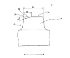
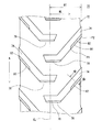
図1は、本発明の一実施形態に係る空気入りタイヤ2の一部が示された展開図である。このタイヤ2は、農業機械(典型的にはトラクタ)に装着される。この図1において、左右方向がタイヤ2の軸方向である。矢印Aで示されているのは、タイヤ2の回転方向である。図1中の一点鎖線CLは、タイヤ2の赤道を表す。
FIG. 1 is a development view showing a part of a
図2は、図1のタイヤ2のII−II線に沿った拡大断面図である。この図2において、上下方向がタイヤ2の半径方向であり、左右方向がタイヤ2の軸方向である。このタイヤ2は、トレッド4、サイドウォール6、ビード8、カーカス10及びベルト12を備えている。図示されていないが、このタイヤ2はチューブを備えている。このチューブに、空気が充填される。
FIG. 2 is an enlarged cross-sectional view along the line II-II of the
トレッド4は架橋ゴムからなり、半径方向外向きに凸な形状を呈している。トレッド4は、多数のラグ14を備えている。ラグ14は、半径方向外向きに突出している。
The
サイドウォール6は、トレッド4の端から半径方向略内向きに延びている。このサイドウォール6は、架橋ゴムからなる。サイドウォール6は、撓みによって路面からの衝撃を吸収する。さらにサイドウォール6は、カーカス10の外傷を防止する。
The
ビード8は、サイドウォール6から半径方向略内向きに延びている。ビード8は、コア16と、このコア16から半径方向外向きに延びるエイペックス18とを備えている。コア16はリング状であり、複数本の非伸縮性ワイヤー(典型的にはスチール製ワイヤー)を含む。エイペックス18は、半径方向外向きに先細りであるテーパ状であり、高硬度な架橋ゴムからなる。
The
カーカス10は、第一プライ20及び第二プライ22からなる。第一プライ20及び第二プライ22は、両側のビード8の間に架け渡されており、トレッド4及びサイドウォール6の内側に沿っている。第一プライ20及び第二プライ22は、軸方向内側から外側に向かってコア16の周りを巻かれている。
The
図示されていないが、第一プライ20及び第二プライ22は、カーカスコードとトッピングゴムとからなる。第一プライ20及び第二プライ22は、赤道に対して傾斜している。傾斜角度の絶対値は、通常は10°以上50°以下である。第一プライ20のカーカスコードの赤道に対する角度は、第二プライ22のカーカスコードの赤道に対する角度とは逆である。カーカスコードは、通常は有機繊維からなる。好ましい有機繊維としては、ポリエステル繊維、ナイロン繊維、レーヨン繊維、ポリエチレンナフタレート繊維及びアラミド繊維が例示される。
Although not shown, the
ベルト12は、カーカス10の半径方向外側に位置している。ベルト12は、カーカス10と積層されている。ベルト12は、カーカス10を補強する。図示されていないが、ベルト12は、ベルトコードとトッピングゴムとからなる。ベルトコードの好ましい材質は、有機繊維である。
The
図1において、これらのラグ14は、タイヤ2の左側及び右側に配置されている。左側のラグ14と右側のラグ14とは、回転方向において交互に配置されている。タイヤ2の回転に伴い、タイヤ2と地面との接地箇所は、左側のラグ14に沿って赤道から左側のトレッド4の端に向かって移行する。トレッド4の端に至った接地箇所は、右側のラグ14の赤道へと移行し、この右側のラグ14に沿って赤道から右側のトレッド4の端に向かって移行する。トレッド4の端に至った接地箇所は、さらに左側のラグ14の赤道へと移行する。回転中は、左側のラグ14から右側のラグ14への接地箇所の移行、及び右側のラグ14から左側のラグ14への接地箇所の移行が繰り返される。左側のラグ14から右側のラグ14への接地箇所の移行、及び右側のラグ14から左側のラグ14への接地箇所の移行は、非連続的である。
In FIG. 1, these
このラグ14は、赤道近傍から軸方向外側に延びる水平部24と、この水平部24の端からトレッド4の端に向かって回転方向後方に斜めに延びる斜方部26とを備えている。この水平部24は、その回転方向側に水平前辺部28と水平側辺部30とを備えている。この斜方部26は、その回転方向側に斜方側辺部32を備えている。このタイヤ2の水平前辺部28は、面取によって形成された緩衝部34を備えている。
The
図3は、図1のタイヤ2のIII−III線に沿った拡大断面図である。この図3において、上下方向がタイヤ2の半径方向である。矢印Aは、このタイヤ2の回転方向を表している。この緩衝部34は、稜が削り取られて形成された平面36を備えている。この緩衝部34が備えられたタイヤ2では、接地時における衝撃は緩和される。接地時の衝撃が緩和されるので、走行時の振動が低減される。したがって、このタイヤ2は、乗り心地に優れる。
FIG. 3 is an enlarged cross-sectional view taken along the line III-III of the
図3中、両矢印線Waは、ラグ14の幅を表している。両矢印線Wbは、この緩衝部34の幅を表している。角度αは、ラグ14の上面38と緩衝部34に備えられる平面36とのなす角度を表している。この角度αは、面取角と称される。このラグ14の幅Waに対する緩衝部34の幅Wbの比率(Wb/Wa)は、5%以上50%以下である。この比率(Wb/Wa)が5%以上に設定されることにより、タイヤ2の質量が低減されるととともに緩衝部34による衝撃緩和効果が大きくなる。衝撃緩和効果の大きなタイヤ2は、振動が低減されるので乗り心地に優れる。この観点から、この比率(Wb/Wa)は、7%以上がより好ましく、10%以上が特に好ましい。この比率(Wb/Wa)が50%以下に設定されることにより、グリップ力が保持されるので、トラクション性能が低下しない。この観点から、この比率(Wb/Wa)は、45%以下がより好ましく、40%以下が特に好ましい。
In FIG. 3, a double arrow line Wa represents the width of the
面取角αは、3°以上10°以下である。この面取角αが3°以上に設定されることにより、タイヤ2質量が低減されるととともに緩衝部34による衝撃緩和効果が大きくなる。衝撃緩和効果の大きなタイヤ2は、振動が低減されるので乗り心地に優れる。この観点から、この面取角αは、4°以上がより好ましく、5°以上が特に好ましい。この面取角αが10°以下に設定されることにより、グリップ力が保持されるので、トラクション性能が低下しない。この観点から、この面取角αは、9°以下がより好ましく、8°以下が特に好ましい。
The chamfering angle α is 3 ° or more and 10 ° or less. By setting the chamfer angle α to 3 ° or more, the mass of the
このタイヤ2の寸法及び角度は、タイヤ2が正規リムに組み込まれ、正規内圧となるようにタイヤ2に空気が充填された状態で測定される。測定時には、タイヤ2には荷重がかけられない。本明細書において正規リムとは、タイヤ2が依拠する規格において定められたリムを意味する。JATMA規格における「標準リム」、TRA規格における「Design Rim」、及びETRTO規格における「Measuring Rim」は、正規リムである。本明細書において正規内圧とは、タイヤ2が依拠する規格において定められた内圧を意味する。JATMA規格における「最高空気圧」、TRA規格における「TIRE LOAD LIMITS AT VARIOUS COLD INFLATION PRESSURES」に掲載された「最大値」、及びETRTO規格における「INFLATION PRESSURE」は、正規内圧である。
The size and angle of the
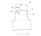
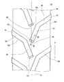
図4は、本発明の他の実施形態に係るタイヤ40の一部が示された展開図である。この図4において、左右方向がタイヤ40の軸方向である。図4中の一点鎖線CLは、タイヤ40の赤道を表す。このタイヤ40に備えられる架橋ゴムからなるトレッド42は、回転方向において左右交互に配置された多数のラグ44を備えている。このタイヤ40においては、そのラグ44に備えられる水平前辺部46が丸めによって形成された緩衝部48を備えている。図示されていないが、このタイヤ40の緩衝部48以外の構成は、図1及び図2のタイヤ2と同じである。
FIG. 4 is a development view showing a part of a
図5は、図4のタイヤ40のV−V線に沿った拡大断面図である。この図5において、上下方向がタイヤ40の半径方向である。なお、矢印Aで示されているのは、タイヤ40の回転方向である。この緩衝部48は、稜が丸められて形成された曲面50を備えている。両矢印線Wcはラグ44の幅を表している。両矢印線Wdは、この緩衝部48の幅を表している。矢印線R1は、この曲面50の曲率半径を表している。このラグ44の幅Wcに対する緩衝部48の幅Wdの比率(Wd/Wc)は、図3で示されたタイヤ40と同じように、5%以上50%以下である。
FIG. 5 is an enlarged cross-sectional view taken along line VV of the
曲率半径R1は、3mm以上10mm以下である。曲率半径R1が3mm以上に設定されることにより、タイヤ40の質量が低減されるととともに緩衝部48による衝撃緩和効果が大きくなる。衝撃緩和効果の大きなタイヤ40は、振動が低減されるので乗り心地に優れる。この観点から、この曲率半径R1は4mm以上がより好ましく、5mm以上が特に好ましい。この曲率半径R1が10mm以下に設定されることにより、グリップ力が保持されるので、トラクション性能が低下しない。この観点から、この曲率半径R1は9mm以下がより好ましく、8mm以下が特に好ましい。
The curvature radius R1 is 3 mm or more and 10 mm or less. By setting the curvature radius R1 to 3 mm or more, the mass of the
図6は、本発明のさらに他の実施形態に係るタイヤ52の一部が示された展開図である。この図6において、左右方向がタイヤ52の軸方向である。図6中の一点鎖線CLは、タイヤ52の赤道を表す。このタイヤ52に備えられる架橋ゴムからなるトレッド54も、回転方向において左右交互に配置される多数のラグ56を備えている。このタイヤ52は、水平前辺部58、水平側辺部60及び斜方側辺部64に丸めによって形成された緩衝部66を備えている。図示されていないが、このタイヤ52の緩衝部66以外の構成は、図1及び図2のタイヤ2と同じである。
FIG. 6 is a development view showing a part of a
図7は、図6のタイヤ52のVII−VII線に沿った拡大断面図である。この緩衝部66は、稜が丸められて形成された曲面68を備えている。なお、この緩衝部66は、稜が削り取られて形成される平面を備えてもよい。図7において、両矢印線Weはラグ56の幅である。両矢印線Wfは、この緩衝部66の幅を表している。矢印線R2は、この曲面68の曲率半径を表している。このラグ56の幅Weに対する緩衝部66の幅Wfの比率は、5%以上50%以下である。この曲率半径R2は、3mm以上10mm以下である。このようなタイヤ52では、衝撃緩和効果が大きいので振動が低減される。したがって、このタイヤ52は、乗り心地に優れる。
FIG. 7 is an enlarged cross-sectional view of the
図8は、本発明のさらに他の実施形態に係るタイヤ70の一部が示された展開図である。このタイヤ70に備えられる架橋ゴムからなるトレッド72も、回転方向において左右交互に配置される多数のラグ74を備えている。この図8において、左右方向がタイヤ70の軸方向である。図8中の一点鎖線CLは、タイヤ70の赤道を表す。なお、矢印Aで示されているのは、タイヤ70の回転方向である。
FIG. 8 is a development view showing a part of a
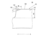
この図8において、斜方側辺部80の点P1は、面取開始点である。点P2は、斜方側辺部80の外端である。両矢印線WLは、赤道からこの点P1までの軸方向距離である。両矢印線WTは赤道からこの点P2までの軸方向距離であり、タイヤ70の最大幅の半分の長さに一致する。このタイヤ70は、水平前辺部76に第一緩衝部78を備えており、この面取開始点P1から外端P2までの斜方側辺部80に第二緩衝部82を備えている。第一緩衝部78及び第二緩衝部82の緩衝部は、面取によって形成されている。このタイヤには、第一緩衝部78及び第二緩衝部82が備えられているので、このタイヤ70も乗り心地に優れる。図示されていないが、このタイヤ70のラグ74に備えられる第一緩衝部78及び第二緩衝部82以外の構成は、図1及び図2のタイヤ2と同じである。
In FIG. 8, a point P1 of the
このタイヤ70の最大幅の半分の長さWTに対する赤道からこの点P1までの軸方向距離WLの比率は、40%以上80%以下である。この比率(WL/WT)が40%以上に設定されることにより、グリップ力が保持されるので、トラクション性能が低下しない。この観点から、この比率(WL/WT)は45%以上がより好ましく、50%以上が特に好ましい。この比率(WL/WT)が80%以下に設定されることにより、タイヤ70質量が低減されるととともに第二緩衝部82による衝撃緩和効果が大きくなる。衝撃緩和効果の大きなタイヤ70は、振動が低減されるので乗り心地に優れる。この観点から、この比率(WL/WT)は75%以下がより好ましく、70%以下が特に好ましい。
The ratio of the axial distance WL from the equator to this point P1 with respect to the length WT which is half the maximum width of the
図9は、図8のタイヤ70のIX−IX線に沿った拡大断面図である。この図9には、第二緩衝部82が示されている。この第二緩衝部82は、稜が削り取られて形成された平面84を備えている。なお、この第二緩衝部82は、稜が丸められて形成される曲面68を備えてもよい。両矢印線Wgは、ラグ74の幅を表している。両矢印線Whは、第二緩衝部82の幅を表している。角度βは、ラグ74の上面86と第二緩衝部82に備えられる平面84とのなす角度を表している。この角度βは、面取角と称される。このラグ74の幅Wgに対する第二緩衝部82の幅Whの比率は、5%以上50%以下である。この面取角βは、3°以上10°以下である。このようなタイヤ70は衝撃緩和効果が大きいので、振動が低減される。したがって、このタイヤ70は、乗り心地に優れる。なお、図示されていないが、第一緩衝部78は、この第二緩衝部82と同一の幅及び面取角で構成されている。
FIG. 9 is an enlarged cross-sectional view along the line IX-IX of the
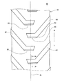
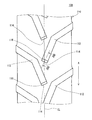
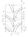
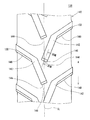
図10は、本発明のさらに他の実施形態に係るタイヤ88の一部が示された展開図である。この図10において、左右方向がタイヤ88の軸方向である。図10中の一点鎖線CLは、タイヤ88の赤道を表す。このタイヤ88に備えられる架橋ゴムからなるトレッド90は、赤道近傍からトレッド90の端近傍まで延びる多数のラグ92を備えている。これらのラグ92は、回転方向において左右交互に配置されている。図示されていないが、このタイヤ88のラグ92以外の構成は、図1及び図2のタイヤ2と同じである。なお、矢印Aで示されているのは、タイヤ88の回転方向である。
FIG. 10 is a development view showing a part of a tire 88 according to still another embodiment of the present invention. In FIG. 10, the left-right direction is the axial direction of the tire 88. A one-dot chain line CL in FIG. 10 represents the equator of the tire 88. A
このラグ92は、赤道近傍から回転方向後方に斜めに延びるセンター部94と、このセンター部94の端からトレッド90の端近傍までさらに斜めに延びるショルダー部96とを備えている。このラグ92は、このショルダー部96の赤道に対する傾斜角度がこのセンター部94の傾斜角度よりも大きくなる形状を有している。このセンター部94は、その回転方向側にセンター前辺部98を備えている。このショルダー部96は、その回転方向側にショルダー側辺部100を備えている。このタイヤ88では、センター前辺部98が、面取によって形成された緩衝部102を備えている。
The
図11は、図10のタイヤ88のXI−XI線に沿った拡大断面図である。この図11において、上下方向がタイヤ88の半径方向である。なお、矢印Aで示されているのは、タイヤ88の回転方向である。この緩衝部102は、稜が削り取られて形成された平面104を備えている。両矢印線Wdは、ラグ92の高さを表している。両矢印線Wcは、緩衝部102の幅を表している。角度γは、ラグ92の上面106と緩衝部102に備えられる平面104とのなす角度を表している。この角度γは、面取角と称される。このラグ92の高さWjに対する緩衝部102の幅Wkの比率(Wk/Wj)は、5%以上50%以下である。この比率(Wk/Wj)が5%以上に設定されることにより、タイヤ88質量が低減されるととともに緩衝部102による衝撃緩和効果が大きくなる。衝撃緩和効果の大きなタイヤ88は、振動が低減されるので乗り心地に優れる。この観点から、この比率(Wk/Wj)は、7%以上がより好ましく、10%以上が特に好ましい。この比率(Wk/Wj)が50%以下に設定されることにより、グリップ力が保持されるので、トラクション性能が低下しない。この観点から、この比率(Wk/Wj)は、45%以下がより好ましく、40%以下が特に好ましい。
FIG. 11 is an enlarged cross-sectional view of the tire 88 of FIG. 10 along the line XI-XI. In FIG. 11, the vertical direction is the radial direction of the tire 88. Note that the direction of rotation of the tire 88 is indicated by an arrow A. The
面取角γは、3°以上10°以下である。この面取角γが3°以上に設定されることにより、タイヤ88の質量が低減されるととともに緩衝部102による衝撃緩和効果が大きくなる。衝撃緩和効果の大きなタイヤ88は、振動が低減されるので乗り心地に優れる。この観点から、この面取角γは、4°以上がより好ましく、5°以上が特に好ましい。この面取角γが10°以下に設定されることにより、グリップ力が保持されるので、トラクション性能が低下しない。この観点から、この面取角γは、9°以下がより好ましく、8°以下が特に好ましい。
The chamfering angle γ is 3 ° or more and 10 ° or less. By setting the chamfering angle γ to 3 ° or more, the mass of the tire 88 is reduced and the impact mitigating effect by the
図12は、本発明のさらに他の実施形態に係るタイヤ108の一部が示された展開図である。この図12において、左右方向がタイヤ108の軸方向である。図12中の一点鎖線CLは、タイヤ108の赤道を表す。このタイヤ108に備えられる架橋ゴムからなるトレッド110も、回転方向において左右交互に配置される多数のラグ112を備えている。このタイヤ108においても、センター前辺部114が丸めによって形成された緩衝部116を備えている。図示されていないが、このタイヤ108に備えられるラグ112の緩衝部116以外の構成は、図10及び図11のタイヤ88と同じである
FIG. 12 is a development view showing a part of a
図13は、図12のタイヤ108のXIII−XIII線に沿った拡大断面図である。この図13において、上下方向がタイヤ108の半径方向である。なお、矢印Aで示されているのは、タイヤ108の回転方向である。この緩衝部116は、稜が丸められて形成された曲面118を備えている。両矢印線Wmは、ラグ112の高さを表している。両矢印線Wnは、緩衝部116の幅を表している。矢印線R3は、この曲面118の曲率半径を表している。このタイヤ108においても、ラグ112の高さWmに対する緩衝部116の幅Wnの比率(Wn/Wm)は、5%以上50%以下である。
FIG. 13 is an enlarged cross-sectional view of the
曲率半径R3は、3mm以上10mm以下である。曲率半径R3が3mm以上に設定されることにより、タイヤ108の質量が低減されるととともに緩衝部116による衝撃緩和効果が大きくなる。衝撃緩和効果の大きなタイヤ108は振動が低減されるので乗り心地に優れる。この観点から、この曲率半径R3は、4mm以上がより好ましく、5mm以上が特に好ましい。この曲率半径R3が10mm以下に設定されることにより、グリップ力が保持されるので、トラクション性能が低下しない。この観点から、この曲率半径R3は、9mm以下がより好ましく、8mm以下が特に好ましい。
The curvature radius R3 is 3 mm or more and 10 mm or less. By setting the curvature radius R3 to 3 mm or more, the mass of the
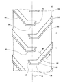
図14は、本発明のさらに他の実施形態に係るタイヤ120の一部が示された展開図である。この図14において、左右方向がタイヤ120の軸方向である。図14中の一点鎖線CLは、タイヤ120の赤道を表す。このタイヤ120に備えられる架橋ゴムからなるトレッド122も、回転方向において左右交互に配置される多数のラグ124を備えている。このタイヤ120は、センター前辺部126に第一緩衝部128を備えており、ショルダー側辺部130に第二緩衝部132を備えている。この第一緩衝部128及び第二緩衝部132は、面取によって形成されている。図示されていないが、このタイヤ120の第一緩衝部128及び第二緩衝部132以外の構成は、図10及び図11のタイヤ88と同じである。
FIG. 14 is a development view showing a part of a
図15は、図14のタイヤ120のXV−XV線に沿った拡大断面図である。この図15において、上下方向がタイヤ120の半径方向である。なお、矢印Aで示されているのは、タイヤ120の回転方向である。この図15には、第一緩衝部128が示されている。この第一緩衝部128は、稜が削り取られて形成された平面134を備えている。両矢印線Woは、タイヤ120の赤道におけるラグ124の高さを表している。両矢印線Wpは、第一緩衝部128の幅を表している。角度δは、ラグ124の上面136と第二緩衝部132に備えられる平面134とのなす角度を表している。この角度δは、面取角と称される。このタイヤ120において、このラグ124の高さWoに対する第一緩衝部128の幅Wpの比率(Wp/Wo)は、5%以上50%以下である。面取角δは、3°以上10°以下である。このようなタイヤ120は衝撃緩和効果が大きいので、振動が低減される。したがって、このタイヤ120は、乗り心地に優れる。なお、図示されていないが、第二緩衝部132は、この第一緩衝部128と同一の幅及び面取角で構成されている。
FIG. 15 is an enlarged cross-sectional view of the
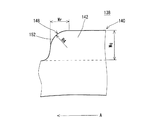
図16は、本発明のさらに他の実施形態に係るタイヤ138の一部が示された展開図である。この図16において、左右方向がタイヤ138の軸方向である。図16中の一点鎖線CLは、タイヤ138の赤道を表す。このタイヤ138に備えられる架橋ゴムからなるトレッド140も、回転方向において左右交互に配置される多数のラグ142を備えている。このタイヤ138は、センター前辺部144に第一緩衝部146を備えており、ショルダー側辺部148に第二緩衝部150を備えている。この第一緩衝部146及び第二緩衝部150は、面取によって形成されている。図示されていないが、このタイヤ138の第一緩衝部148及び第二緩衝部150以外の構成は、図10及び図11のタイヤ88と同じである。
FIG. 16 is a development view showing a part of a
図17は、図16のタイヤ138のXVII−XVII線に沿った拡大断面図である。この図17において、上下方向がタイヤ138の半径方向である。なお、矢印Aで示されているのは、タイヤ138の回転方向である。この図17には、第一緩衝部148が示されている。この第一緩衝部148は、稜が丸められて形成された曲面152を備えている。両矢印線Wqは、タイヤ138の赤道におけるラグ142の高さを表している。両矢印線Wrは、第一緩衝部148の幅を表している。矢印線R4は、この曲面152の曲率半径を表している。このタイヤ138においても、このラグ142の高さWqに対する第一緩衝部148の幅Wrの比率(Wr/Wq)は、5%以上50%以下である。曲率半径R4は、3mm以上10mm以下である。このようなタイヤ138は衝撃緩和効果が大きいので、振動が低減される。したがって、このタイヤ138は、乗り心地に優れる。なお、図示されていないが、第二緩衝部150は、この第一緩衝部148と同一の幅及び曲率半径で構成されている。
17 is an enlarged cross-sectional view of the
以下、実施例によって本発明の効果が明らかにされるが、この実施例の記載に基づいて本発明が限定的に解釈されるべきではない。 Hereinafter, the effects of the present invention will be clarified by examples. However, the present invention should not be construed in a limited manner based on the description of the examples.
[実験1 ラグに水平部及び斜方部が備えられたタイヤ]
[実施例1]
図1、図2及び図3に示された基本構成が備えられ、下記表1に示された仕様を備えた実施例1のタイヤを得た。このタイヤサイズは、13.6−24である。カーカスには、第一プライ及び第二プライを用いた。この第一プライ及び第二プライに用いられているコード材質は、ナイロン繊維である。このコードの回転方向に対してなす角度は、35°である。ラグの幅に対する緩衝部の幅の比率は、30%である。面取角は、5°である。
[Experiment 1 Tire with a horizontal part and an oblique part on the lug]
[Example 1]
A tire of Example 1 having the basic configuration shown in FIGS. 1, 2 and 3 and having the specifications shown in Table 1 below was obtained. The tire size is 13.6-24. A first ply and a second ply were used for the carcass. The cord material used for the first ply and the second ply is nylon fiber. The angle formed with respect to the rotation direction of the cord is 35 °. The ratio of the width of the buffer portion to the width of the lug is 30%. The chamfer angle is 5 °.
[比較例2及び3並びに実施例2、3、4、7及び8]
ラグの幅に対する緩衝部の幅の比率を下記表1及び表2に示される通りとした他は実施例1と同様にして、タイヤを得た。
[Comparative Examples 2 and 3 and Examples 2, 3, 4, 7 and 8]
A tire was obtained in the same manner as in Example 1 except that the ratio of the width of the buffer portion to the width of the lug was as shown in Tables 1 and 2 below.
[実施例5及び6]
面取角を下記表1に示される通りとした他は実施例1と同様にして、タイヤを得た。
[Examples 5 and 6]
A tire was obtained in the same manner as in Example 1 except that the chamfer angle was changed as shown in Table 1 below.
[比較例1]
緩衝部が備えられていない他は実施例1と同様にして、タイヤを得た。このタイヤは、市販のタイヤである。
[Comparative Example 1]
A tire was obtained in the same manner as in Example 1 except that the buffer portion was not provided. This tire is a commercially available tire.
[実施例9から13]
図4及び図5に示された基本構成が備えられ、下記表2に示された仕様を備えた実施例9から13のタイヤを得た。これらのタイヤは、ラグに備えられる緩衝部以外の構成は、実施例1と同様である。
[Examples 9 to 13]
Tires of Examples 9 to 13 having the basic configuration shown in FIGS. 4 and 5 and having the specifications shown in Table 2 below were obtained. These tires have the same configuration as that of the first embodiment except for the buffer portion provided in the lug.
[実施例14]
図8及び図9に示された基本構成が備えられ、下記表2に示された仕様を備えた実施例14のタイヤを得た。これらのタイヤは、ラグに備えられる緩衝部以外の構成は、実施例1と同様である。
[Example 14]
A tire of Example 14 having the basic configuration shown in FIGS. 8 and 9 and having the specifications shown in Table 2 below was obtained. These tires have the same configuration as that of the first embodiment except for the buffer portion provided in the lug.
[実施例15]
図6及び図7に示された基本構成が備えられ、下記表2に示された仕様を備えた実施例15のタイヤを得た。これらのタイヤは、ラグに備えられる緩衝部以外の構成は、実施例1と同様である。
[Example 15]
A tire of Example 15 having the basic configuration shown in FIGS. 6 and 7 and having the specifications shown in Table 2 below was obtained. These tires have the same configuration as that of the first embodiment except for the buffer portion provided in the lug.
[振動性評価]
農業用トラクタに、試作タイヤが装着された。リムは24×W11、タイヤ空気内圧は100kPaとした。畑及び湿田が模擬されたテストコースで、走行試験が実施され、運転者による10点が満点とされた振動性に関する官能評価を行った。この数値が大きいほど、振動低減効果が大きく、乗り心地に優れることが示される。この結果が、下記の表1及び表2に示されている。
[Vibration evaluation]
A prototype tire was mounted on an agricultural tractor. The rim was 24 × W11 and the tire air pressure was 100 kPa. A driving test was conducted on a test course simulating fields and wetlands, and a driver's sensory evaluation on vibration was performed with 10 points being full. It is shown that the larger this value, the greater the vibration reduction effect and the better the ride comfort. The results are shown in Tables 1 and 2 below.
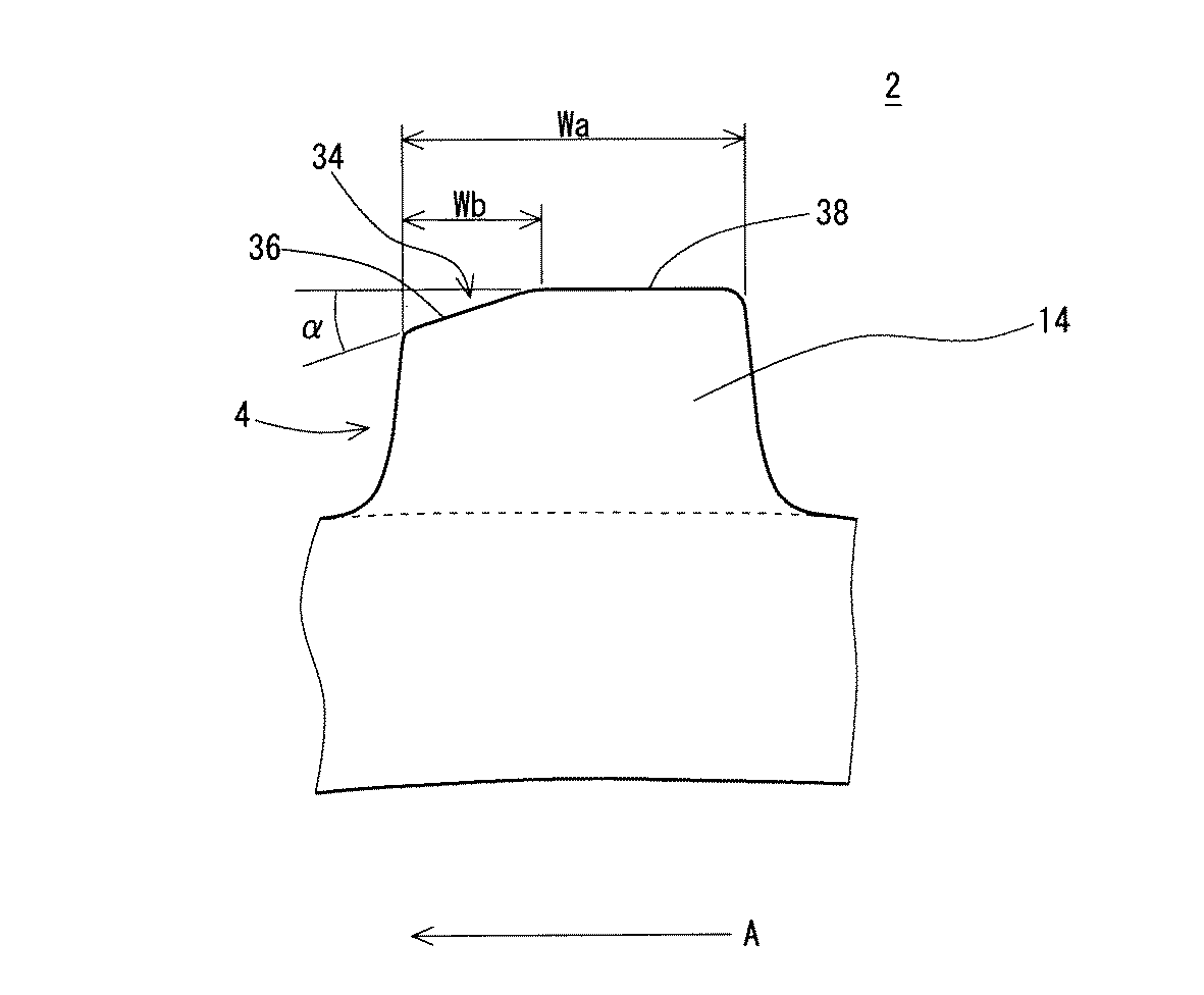
表1及び表2に示されるように、実施例のタイヤでは振動低減効果が大きいので、乗り心地が向上している。 As shown in Tables 1 and 2, the tires of the examples have a great vibration reduction effect, so that the riding comfort is improved.
[実験2 ラグにセンター部及びショルダー部が備えられたタイヤ]
[実施例19]
図10及び図11に示された基本構成が備えられ、下記表3に示された仕様を備えた実施例19のタイヤを得た。このタイヤサイズは、13.6−24である。カーカスには、第一プライ及び第二プライを用いた。この第一プライ及び第二プライに用いられているコード材質は、ナイロン繊維である。このコードの回転方向に対してなす角度は、35°である。ラグの高さに対する緩衝部の幅の比率は、30%である。面取角は、5°である。
[Experiment 2: Tire with center and shoulder on lug]
[Example 19]
A tire of Example 19 having the basic configuration shown in FIGS. 10 and 11 and having the specifications shown in Table 3 below was obtained. The tire size is 13.6-24. A first ply and a second ply were used for the carcass. The cord material used for the first ply and the second ply is nylon fiber. The angle formed with respect to the rotation direction of the cord is 35 °. The ratio of the buffer width to the lug height is 30%. The chamfer angle is 5 °.
[比較例5及び6並びに実施例16、17及び21]
ラグの高さに対する緩衝部の幅の比率を下記表3に示される通りとした他は実施例19と同様にして、タイヤを得た。
[Comparative Examples 5 and 6 and Examples 16, 17 and 21]
A tire was obtained in the same manner as in Example 19 except that the ratio of the width of the buffer portion to the height of the lug was as shown in Table 3 below.
[実施例18及び20]
面取角を下記表3に示される通りとした他は実施例19と同様にして、タイヤを得た。
[Examples 18 and 20]
A tire was obtained in the same manner as in Example 19 except that the chamfer angle was changed as shown in Table 3 below.
[比較例4]
緩衝部が備えられていない他は実施例19と同様にして、タイヤを得た。このタイヤは、市販のタイヤである。
[Comparative Example 4]
A tire was obtained in the same manner as in Example 19 except that the buffer portion was not provided. This tire is a commercially available tire.
[実施例22から26]
図12及び図13に示された基本構成が備えられ、下記表4に示された仕様を備えた実施例22から26のタイヤを得た。これらのタイヤは、ラグに備えられる緩衝部以外の構成は、実施例19と同様である。
[Examples 22 to 26]
Tires of Examples 22 to 26 having the basic configuration shown in FIGS. 12 and 13 and having the specifications shown in Table 4 below were obtained. These tires have the same configuration as that of Example 19 except for the buffer portion provided in the lug.
[実施例27]
図14及び図15に示された基本構成が備えられ、下記表4に示された仕様を備えた実施例27のタイヤを得た。これらのタイヤは、ラグに備えられる緩衝部以外の構成は、実施例19と同様である。
[Example 27]
A tire of Example 27 having the basic configuration shown in FIGS. 14 and 15 and having the specifications shown in Table 4 below was obtained. These tires have the same configuration as that of Example 19 except for the buffer portion provided in the lug.
[実施例15]
図16及び図17に示された基本構成が備えられ、下記表4に示された仕様を備えた実施例28のタイヤを得た。これらのタイヤは、ラグに備えられる緩衝部以外の構成は、実施例19と同様である。
[Example 15]
A tire of Example 28 having the basic configuration shown in FIGS. 16 and 17 and having the specifications shown in Table 4 below was obtained. These tires have the same configuration as that of Example 19 except for the buffer portion provided in the lug.
[振動性評価]
農業用トラクタに、試作タイヤが装着された。リムは24×W11、タイヤ空気内圧は100kPaとした。畑及び湿田が模擬されたテストコースで、走行試験が実施され、運転者による10点が満点とされた振動性に関する官能評価を行った。この数値が大きいほど、振動低減効果が大きく、乗り心地に優れることが示される。この結果が、下記の表3及び表4に示されている。
[Vibration evaluation]
A prototype tire was mounted on an agricultural tractor. The rim was 24 × W11 and the tire air pressure was 100 kPa. A driving test was conducted on a test course simulating fields and wetlands, and a driver's sensory evaluation on vibration was performed with 10 points being full. It is shown that the larger this value, the greater the vibration reduction effect and the better the ride comfort. The results are shown in Tables 3 and 4 below.
表3及び表4に示されるように、実施例のタイヤでは振動低減効果が大きいので、乗り心地が向上している。以上の評価結果から、本発明の優位性は明らかである。 As shown in Tables 3 and 4, the tires of the examples have a great vibration reduction effect, so that the ride comfort is improved. From the above evaluation results, the superiority of the present invention is clear.
本発明に係る空気入りタイヤは、種々の農業機械に装着されうる。 The pneumatic tire according to the present invention can be mounted on various agricultural machines.
2、40、52、70、88、108、120、138・・・タイヤ
4、42、54、72、90、110、122、140・・・トレッド
6・・・サイドウォール
8・・・ビード
10・・・カーカス
12・・・ベルト
14、44、56、74、92、112、124、142・・・ラグ
16・・・コア
18・・・エイペックス
20・・・第一プライ
22・・・第二プライ
24・・・水平部
26・・・斜方部
28、46、58、76・・・水平前辺部
30、60・・・水平側辺部
32、64、80・・・斜方側辺部
34、48、66、82、102、116、132、150・・・緩衝部
36、84、104、134・・・平面
38、86、106、136・・・上面
50、68、118、152・・・曲面
78、128、146・・・第一緩衝部
82、132、150・・・第二緩衝部
94・・・センター部
96・・・ショルダー部
98、114、126、144・・・センター前辺部
100、130、148・・・ショルダー側辺部
2, 40, 52, 70, 88, 108, 120, 138 ...
Claims (11)
このトレッドが、赤道近傍からトレッド端近傍まで延びる多数のラグを備えており、
これらのラグが、回転方向において左右交互に配置されており、
このラグが、赤道近傍から軸方向外側に延びる水平部と、この水平部の端からトレッドの端に向かって回転方向後方に斜めに延びる斜方部とを備えており、
この水平部が、その回転方向側に水平前辺部と水平側辺部とを備えており、
この水平前辺部が、面取又は丸めによって形成された緩衝部を備えており、
このラグの幅に対するこの緩衝部の幅の比率が、5%以上50%以下であるタイヤ。 It has a tread made of crosslinked rubber,
This tread has a number of lugs extending from the equator vicinity to the tread edge,
These lugs are arranged alternately on the left and right in the rotation direction,
The lug includes a horizontal portion extending outward in the axial direction from the vicinity of the equator, and an oblique portion extending obliquely rearward in the rotational direction from the end of the horizontal portion toward the end of the tread.
This horizontal part is provided with a horizontal front side part and a horizontal side part on the rotational direction side,
This horizontal front side has a buffer part formed by chamfering or rounding,
A tire in which the ratio of the width of the buffer portion to the width of the lug is 5% or more and 50% or less.
上記水平側辺部及びこの斜方側辺部が、面取又は丸めによって形成された緩衝部を備えている請求項1に記載のタイヤ。 The oblique part includes an oblique side part on the rotational direction side,
The tire according to claim 1, wherein the horizontal side portion and the oblique side portion are provided with a buffer portion formed by chamfering or rounding.
上記ラグの上面とこの平面とのなす角度が、3°以上10°以下である請求項1又は2に記載のタイヤ。 The buffer portion includes a flat surface formed by cutting off a ridge,
The tire according to claim 1 or 2, wherein an angle formed between the upper surface of the lug and the plane is 3 ° or more and 10 ° or less.
この曲面の曲率半径が、3mm以上10mm以下である請求項1又は2に記載のタイヤ。 The buffer portion has a curved surface formed by rounding the ridge,
The tire according to claim 1 or 2, wherein a radius of curvature of the curved surface is 3 mm or more and 10 mm or less.
赤道からこの外端までの軸方向距離に対する赤道からこの面取開始点までの軸方向距離の比率が、40%以上80%以下であり、
この面取開始点から外端までの斜方側辺部が、面取又は丸めによって形成された緩衝部を備えている請求項1に記載のタイヤ。 The oblique side portion includes a chamfer start point and an outer end,
The ratio of the axial distance from the equator to the chamfer start point to the axial distance from the equator to the outer edge is 40% or more and 80% or less,
The tire according to claim 1, wherein the oblique side portion from the chamfer start point to the outer end includes a buffer portion formed by chamfering or rounding.
上記ラグの上面とこの平面とのなす角度が、3°以上10°以下である請求項1又は5に記載のタイヤ。 The buffer portion includes a flat surface formed by cutting off a ridge,
The tire according to claim 1 or 5, wherein an angle formed between the upper surface of the lug and the plane is 3 ° or more and 10 ° or less.
この曲面の曲率半径が、3mm以上10mm以下である請求項1又は5に記載のタイヤ。 The buffer portion has a curved surface formed by rounding the ridge,
The tire according to claim 1 or 5, wherein a radius of curvature of the curved surface is 3 mm or more and 10 mm or less.
このトレッドが、赤道近傍からトレッド端近傍まで延びる多数のラグを備えており、
これらのラグが、回転方向において左右交互に配置されており、
このラグが、赤道近傍から回転方向後方に斜めに延びるセンター部と、このセンター部の端からトレッド端近傍までさらに斜めに延びるショルダー部とを備えており、
このラグが、このショルダー部の赤道に対する傾斜角度がこのセンター部の傾斜角度よりも大きくなる形状を有しており、
このセンター部が、その回転方向側にセンター前辺部を備えており、
このセンター前辺部が、面取又は丸めによって形成された緩衝部を備えており、
このラグの高さに対するこの緩衝部の幅の比率が、5%以上50%以下であるタイヤ。 It has a tread made of crosslinked rubber,
This tread has a number of lugs extending from the equator vicinity to the tread edge,
These lugs are arranged alternately on the left and right in the rotation direction,
The lug includes a center portion extending obliquely rearward in the rotational direction from the vicinity of the equator, and a shoulder portion extending further obliquely from the end of the center portion to the vicinity of the tread end,
This lug has a shape in which the inclination angle of the shoulder portion with respect to the equator is larger than the inclination angle of the center portion,
This center part has a center front side part on the rotational direction side,
This center front side has a buffer part formed by chamfering or rounding,
A tire in which the ratio of the width of the buffer portion to the height of the lug is 5% or more and 50% or less.
このショルダー側辺部が、面取又は丸めによって形成された緩衝部を備えている請求項6に記載のタイヤ。 The shoulder portion includes a shoulder side portion on the rotational direction side thereof,
The tire according to claim 6, wherein the shoulder side portion includes a buffer portion formed by chamfering or rounding.
上記ラグの上面とこの平面とのなす角度が、3°以上10°以下である請求項6又は7に記載のタイヤ。 The buffer portion includes a flat surface formed by cutting off a ridge,
The tire according to claim 6 or 7, wherein an angle formed by the upper surface of the lug and the flat surface is 3 ° or more and 10 ° or less.
この曲面の曲率半径が、3mm以上10mm以下である請求項6又は7に記載のタイヤ。
The buffer portion has a curved surface formed by rounding the ridge,
The tire according to claim 6 or 7, wherein the curvature radius of the curved surface is 3 mm or more and 10 mm or less.
Priority Applications (1)
| Application Number | Priority Date | Filing Date | Title |
|---|---|---|---|
| JP2005102390A JP2006281908A (en) | 2005-03-31 | 2005-03-31 | Pneumatic tire |
Applications Claiming Priority (1)
| Application Number | Priority Date | Filing Date | Title |
|---|---|---|---|
| JP2005102390A JP2006281908A (en) | 2005-03-31 | 2005-03-31 | Pneumatic tire |
Publications (1)
| Publication Number | Publication Date |
|---|---|
| JP2006281908A true JP2006281908A (en) | 2006-10-19 |
Family
ID=37404272
Family Applications (1)
| Application Number | Title | Priority Date | Filing Date |
|---|---|---|---|
| JP2005102390A Pending JP2006281908A (en) | 2005-03-31 | 2005-03-31 | Pneumatic tire |
Country Status (1)
| Country | Link |
|---|---|
| JP (1) | JP2006281908A (en) |
Cited By (1)
| Publication number | Priority date | Publication date | Assignee | Title |
|---|---|---|---|---|
| JP2010274861A (en) * | 2009-05-29 | 2010-12-09 | Bridgestone Corp | Pneumatic tire |
-
2005
- 2005-03-31 JP JP2005102390A patent/JP2006281908A/en active Pending
Cited By (1)
| Publication number | Priority date | Publication date | Assignee | Title |
|---|---|---|---|---|
| JP2010274861A (en) * | 2009-05-29 | 2010-12-09 | Bridgestone Corp | Pneumatic tire |
Similar Documents
| Publication | Publication Date | Title |
|---|---|---|
| JP5161933B2 (en) | Motorcycle tires for running on rough terrain | |
| JP4814980B2 (en) | Pneumatic tire for running on rough terrain | |
| JP2009067245A (en) | Pneumatic tire for irregular ground traveling | |
| JP4287877B2 (en) | Pneumatic tire for running on rough terrain | |
| JP4723310B2 (en) | Pneumatic tire | |
| JP2008120351A (en) | Pneumatic tire for off-road traveling | |
| JP2007015596A (en) | Tire for passenger car | |
| JP5410517B2 (en) | Motorcycle tires | |
| TW201639726A (en) | Motorcycle pneumatic tire | |
| JP2008285004A (en) | Pneumatic tire | |
| JP5322697B2 (en) | Pneumatic tires for motorcycles | |
| JP4910782B2 (en) | Pneumatic tire | |
| JP2007076594A (en) | Pneumatic tire | |
| JP5293015B2 (en) | Racing tire bias tire | |
| JP2001180226A (en) | Tire for motorcycle | |
| JP2004189193A (en) | Radial-ply tire for all terrain vehicle | |
| JP2006312339A (en) | Pneumatic tire | |
| JP2006281908A (en) | Pneumatic tire | |
| JP2007168684A (en) | Tire with lug | |
| JP2009029211A (en) | Pneumatic tire for motorcycle | |
| JP3967939B2 (en) | Radial tire for ATV | |
| JP2007168520A (en) | Tire with lugs | |
| JP2007099152A (en) | Tire for motorcycle | |
| JP2003326916A (en) | Pneumatic tire | |
| JP4570979B2 (en) | Agricultural tire with lugs |
Legal Events
| Date | Code | Title | Description |
|---|---|---|---|
| A977 | Report on retrieval |
Free format text: JAPANESE INTERMEDIATE CODE: A971007 Effective date: 20080425 |
|
| A131 | Notification of reasons for refusal |
Free format text: JAPANESE INTERMEDIATE CODE: A131 Effective date: 20080513 |
|
| A02 | Decision of refusal |
Free format text: JAPANESE INTERMEDIATE CODE: A02 Effective date: 20090414 |