JP2006272702A - Liquid ejection device - Google Patents
Liquid ejection device Download PDFInfo
- Publication number
- JP2006272702A JP2006272702A JP2005093941A JP2005093941A JP2006272702A JP 2006272702 A JP2006272702 A JP 2006272702A JP 2005093941 A JP2005093941 A JP 2005093941A JP 2005093941 A JP2005093941 A JP 2005093941A JP 2006272702 A JP2006272702 A JP 2006272702A
- Authority
- JP
- Japan
- Prior art keywords
- liquid
- diaphragm
- piezoelectric
- ceramic layer
- electrode
- Prior art date
- Legal status (The legal status is an assumption and is not a legal conclusion. Google has not performed a legal analysis and makes no representation as to the accuracy of the status listed.)
- Granted
Links
Images

Abstract
Description
本発明は、液体吐出装置に関し、特にインクジェットプリンタやインクジェットプロッタ等の記録装置、液体供給装置及び液体噴射装置に好適に使用できる液体吐出装置に関する。 The present invention relates to a liquid ejecting apparatus, and more particularly to a liquid ejecting apparatus that can be suitably used for a recording apparatus such as an ink jet printer or an ink jet plotter, a liquid supply apparatus, and a liquid ejecting apparatus.
近年、微小な液滴を液体吐出口から吐出する液体吐出装置は、インクジェットプリンタやインクジェットプロッタなどの消費者向けのプリンタだけでなく、例えば、電子回路の形成や液晶ディスプレイ用のカラーフィルタの製造、有機ELディスプレイの製造といった工業用途にも、利用され始めている。 In recent years, liquid ejection devices that eject minute droplets from liquid ejection ports are not only printers for consumers such as inkjet printers and inkjet plotters, but also the formation of electronic circuits and the manufacture of color filters for liquid crystal displays, It is also beginning to be used in industrial applications such as the manufacture of organic EL displays.
このような液体吐出装置は主操作方向に移動するとともに、記録紙や振動板等を主走査方向と交差する副走査方向に移動させながら、液体吐出装置の液体吐出口から断続的に液滴を吐出させることにより記録が行われる。ここで記録とは、プリンタの場合には、記録紙等の表面に文字の印字や画像の描画を行うことであり、工業用途の場合には、振動板等の表面に絶縁層、誘電体層、電子回路、液晶ディスプレイのカラーフィルタ、有機ELディスプレイの発光セル等を形成することができる。 Such a liquid ejection device moves in the main operation direction, and intermittently ejects liquid droplets from the liquid ejection port of the liquid ejection device while moving the recording paper, the diaphragm, etc. in the sub-scanning direction intersecting the main scanning direction. Recording is performed by discharging. The term “recording” as used herein refers to printing characters or images on the surface of recording paper in the case of a printer. In industrial applications, an insulating layer or dielectric layer is formed on the surface of a diaphragm or the like. Electronic circuits, color filters for liquid crystal displays, light emitting cells for organic EL displays, and the like can be formed.
これらの用途においては、大量の微小領域に分割された各領域に、特定の量の液滴を、高速で、且つ正確な位置に繰り返し吐出するため、液体吐出口が高密度に配置されるようになってきた。 In these applications, liquid discharge ports are arranged at high density in order to repeatedly discharge a specific amount of droplets to each region divided into a large number of minute regions at high speeds and accurately. It has become.
液滴を吐出する液体吐出口は、液体加圧室に連通しており、液体加圧室に充填された液体に圧力を加えることによって、液滴を液体吐出口から吐出させることができる。このような加圧方法としては、圧電方式、加熱方式、静電方式等がある。 The liquid discharge port that discharges the liquid droplets communicates with the liquid pressurizing chamber, and the liquid droplets can be discharged from the liquid discharge port by applying pressure to the liquid filled in the liquid pressurizing chamber. Examples of such a pressurizing method include a piezoelectric method, a heating method, and an electrostatic method.
圧電方式は、圧電アクチュエータの変形によって液体加圧室の容積を増減させて液体を加圧するものであり、有機溶媒や酸性又はアルカリ性の液体を用いられる工業用途では、液体の種類に制限が少なく、しかも、耐久性にも優れた圧電方式が注目されている。 The piezoelectric method is to pressurize the liquid by increasing / decreasing the volume of the liquid pressurizing chamber by deformation of the piezoelectric actuator, and there are few restrictions on the type of liquid in industrial applications where organic solvents or acidic or alkaline liquids are used, In addition, a piezoelectric method having excellent durability has attracted attention.
圧電方式を利用したインクジェット記録装置に用いられる印刷ヘッドは、例えば図3(a)に示したように、圧電アクチュエータ51が、流路部材53の上に設けられた構造を有する(例えば、特許文献1参照)。圧電流路部材53は、複数の液体加圧室53aが隔壁53bによって仕切られ、液体加圧室53aは圧電アクチュエータ51に当接するように並設されている。
A print head used in an inkjet recording apparatus using a piezoelectric method has a structure in which a
圧電アクチュエータ51は、共通電極54を表面に形成した振動板52上に圧電セラミック層55を設け、圧電セラミック層55の上に駆動電極56を設けてなる。換言すれば、駆動電極56と、共通電極54の駆動電極56に対向する対向部位54aと、駆動電極56及び対向部位54aで挟持される圧電セラミック層55の挟持領域55aと、で形成される変位素子57を、振動板52の上に複数配設してなるものである。
The
この変位素子は、近年、薄層化が進み、変位素子には圧電体の抗電界以上の電圧を印加することが増加してきた。 In recent years, the displacement element has been made thinner, and the displacement element has been increasingly applied with a voltage higher than the coercive electric field of the piezoelectric body.
また、駆動電極56は、図3(b)に示したように、圧電セラミック層55の表面に複数配列されることにより、複数の変位素子57が形成されたものである。通常は、マトリックス配置をするように駆動電極56が形成される。この圧電アクチュエータ51は、液体加圧室53aの直上に駆動電極56が位置するようにして流路部材53上に配置している。
Further, as shown in FIG. 3B, a plurality of
このような印刷ヘッドは、共通電極54と所定の駆動電極56との間に電圧を印加して駆動電極56直下の圧電セラミック層55の挟持領域55aを変位させることにより、変位領域57aが対応する液体加圧室53aの方向に凸になるように変形し、液体加圧室53a内のインクを加圧して、流路部材53の底面に開口した液体吐出口58より液滴を吐出することができる。
In such a print head, a voltage is applied between the
このような圧電アクチュエータ51を使用する際には、圧電セラミック層55を分極処理して、変位量を大きくし、液滴の吐出性能を高めることが行われる。例えば、共通電極54と駆動電極56に電圧を印加して、これらの電極に挟持された圧電セラミック層55の部位を特定の方向に分極することが開示されている(例えば、特許文献2参照)。
When such a
ところが、圧電セラミック層55の分極は、時間の経過と共に次第に劣化するため、変位特性が徐々に低下し、その結果、液滴の吐出特性も低下するという問題があった。
However, since the polarization of the piezoelectric
そこで、圧電アクチュエータ51の経時的な劣化に対して、特に、抗電界以上の電圧を印加する場合には、その駆動履歴の違いに関係なく、圧電体を均一に再分極させて、その変位性能を十分に、しかも均一に回復させることが提案されている(例えば、特許文献3参照)。
しかしながら、特許文献1に記載の圧電アクチュエータは、繰り返し変位して特性の劣化した圧電セラミック層を再分極によって変位特性を回復できるものの、さらに繰り返し変位を行うと再び再分極が必要となり、液体吐出装置を頻繁に停止させて再分極処理を行わなければならないという問題があった。 However, although the piezoelectric actuator described in Patent Document 1 can recover the displacement characteristics by repolarizing a piezoelectric ceramic layer whose characteristics have been degraded repeatedly by repolarization, repolarization is necessary again when repeated displacement occurs, and the liquid ejection device There has been a problem that the repolarization process must be performed with frequent stoppage.
そこで、本発明は、繰り返し変位させても変位特性が劣化しにくく、長期的な変位の安定性が高い液体吐出装置を提供することを目的とする。 Accordingly, an object of the present invention is to provide a liquid ejection apparatus that is less likely to deteriorate in displacement characteristics even when repeatedly displaced and has high long-term displacement stability.
本発明の液体吐出装置は、
(1)液体が充填される液体加圧室と、該液体加圧室に連通する液体吐出口と、を具備する流路部材と、
(2)圧電セラミック層を一対の電極層で挟持してなる圧電素子が、圧電セラミック層からなる振動板の上に設けられてなり、前記一対の電極層に電界を印加して前記圧電素子を変形させることで、前記振動板の一部を含む前記圧電素子全体が変形する圧電アクチュエータと、
を有し、圧電アクチュエータの変形によって液体加圧室の容積を増減させることで、液体加圧室の液体を、液体吐出口を通して液滴として吐出させる液体吐出装置であって、
前記流路部材が導電性材料からなり、前記流路部材と前記電極層との間に電圧を加えることで、前記圧電セラミック層の分極方向と反対の方向に、前記振動板の少なくとも一部を分極してなることを特徴とする。
The liquid ejection device of the present invention is
(1) a flow path member including a liquid pressurizing chamber filled with a liquid and a liquid discharge port communicating with the liquid pressurizing chamber;
(2) A piezoelectric element formed by sandwiching a piezoelectric ceramic layer between a pair of electrode layers is provided on a diaphragm made of a piezoelectric ceramic layer, and an electric field is applied to the pair of electrode layers to A piezoelectric actuator that deforms the entire piezoelectric element including a part of the diaphragm by deforming;
A liquid ejection device that ejects the liquid in the liquid pressurization chamber as droplets through the liquid ejection port by increasing or decreasing the volume of the liquid pressurization chamber by deformation of the piezoelectric actuator,
The flow path member is made of a conductive material, and by applying a voltage between the flow path member and the electrode layer, at least a part of the diaphragm is placed in a direction opposite to the polarization direction of the piezoelectric ceramic layer. It is characterized by being polarized.
特に、前記変位素子が前記振動板の上にマトリックス状に複数設けられてなることが好ましい。 In particular, it is preferable that a plurality of the displacement elements are provided in a matrix on the diaphragm.
また、前記振動板の厚みが、5〜50μmであることが好ましい。 The thickness of the diaphragm is preferably 5 to 50 μm.
さらに、前記振動板の分極を行うための制御手段を具備することが好ましい。 Furthermore, it is preferable to provide a control means for performing polarization of the diaphragm.
また、前記液体加圧室に導電性を有する液体を充填し、前記振動板の分極のために、前記液体加圧室に充填された液体を一方の電極として用いることが好ましい。 Further, it is preferable that the liquid pressurizing chamber is filled with a conductive liquid, and the liquid filled in the liquid pressurizing chamber is used as one electrode for polarization of the diaphragm.
本発明は、振動板に圧電体を使用しても、該圧電体を、変位素子を構成する圧電セラミック層と逆方向に分極すれば、圧電体のコンプライアンスを高めて耐久性を向上できるとの知見を得、その結果、繰り返し変位させても変位特性が劣化しにくい圧電アクチュエータを使用して、安定して長期間駆動せしめることができる液体吐出装置を実現したものである。 According to the present invention, even if a piezoelectric body is used for the diaphragm, if the piezoelectric body is polarized in the opposite direction to the piezoelectric ceramic layer constituting the displacement element, the compliance of the piezoelectric body can be increased and the durability can be improved. As a result, a liquid ejecting apparatus that can be stably driven for a long period of time is realized by using a piezoelectric actuator whose displacement characteristics are unlikely to deteriorate even when repeatedly displaced.
即ち、従来の圧電アクチュエータにおいては、変位素子の変形領域の境界において電極層がクリープによって次第に縮むため、徐々に圧電素子に作用する圧縮応力が増加して変位特性を低下させるため、再分極しても変位性能が十分に回復しないという現象が生じていた。そこで、振動板に使用する圧電体を、変位素子を構成する圧電セラミック層と逆方向に分極すれば、圧電体のコンプライアンスを高めることができ、電極層のクリープ変形を抑制し、圧電アクチュエータの特性劣化を防止することができる。 That is, in the conventional piezoelectric actuator, since the electrode layer gradually contracts due to creep at the boundary of the deformation region of the displacement element, the compressive stress acting on the piezoelectric element gradually increases and deteriorates the displacement characteristics. However, there was a phenomenon that the displacement performance was not fully recovered. Therefore, if the piezoelectric body used for the diaphragm is polarized in the opposite direction to the piezoelectric ceramic layer that constitutes the displacement element, the compliance of the piezoelectric body can be increased, the creep deformation of the electrode layer can be suppressed, and the characteristics of the piezoelectric actuator can be suppressed. Deterioration can be prevented.
本発明の液体吐出装置を、インクジェットヘッドに適用した場合を例として取り上げて説明する。 The case where the liquid ejection apparatus of the present invention is applied to an inkjet head will be described as an example.
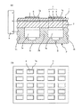
図1は、本発明の液体吐出装置を用いたインクジェットヘッドの概略の断面図に、一部の回路制御を付け加えた説明図である。 FIG. 1 is an explanatory diagram in which a part of circuit control is added to a schematic cross-sectional view of an ink jet head using a liquid ejection apparatus of the present invention.
図1によれば、本発明の液体吐出装置に用いる圧電アクチュエータ1は、流路部材3の上に設けられた構造を有する(例えば、特許文献1参照)。圧電流路部材3は、複数の液体加圧室3aが隔壁3bによって仕切られ、液体加圧室3aは圧電アクチュエータ1に当接するように並設されている。
According to FIG. 1, the piezoelectric actuator 1 used for the liquid ejection apparatus of the present invention has a structure provided on the flow path member 3 (see, for example, Patent Document 1). In the piezoelectric flow path member 3, a plurality of liquid pressurizing
圧電アクチュエータ1は、共通電極4を表面に形成した振動板2上に圧電セラミック層5を設け、圧電セラミック層5の上に駆動電極6を設けてなる。換言すれば、変位素子7を、圧電セラミック層を一対の電極層で挟持してなるものと定義すれば、圧電アクチュエータ1は、駆動電極6と、共通電極4の駆動電極6に対向する対向部位と、駆動電極6及び対向部位で挟持される圧電セラミック層5の挟持領域と、で形成される変位素子7を、振動板2の上に複数配設してなるものである。
The piezoelectric actuator 1 includes a piezoelectric ceramic layer 5 provided on a diaphragm 2 having a
駆動電極6は、図1(b)に示したように、圧電セラミック層5の表面に複数配列されることにより、複数の変位素子7が形成されたものである。通常は、マトリックス配置をするように駆動電極6が形成される。この圧電アクチュエータ1は、液体加圧室3aの直上に駆動電極6が位置するようにして流路部材3上に配置している。このような構成により、液体吐出口8を高密度に形成することができ、インクジェットヘッドとして使用すると、より高精細な印刷を行うことができる。
As shown in FIG. 1B, a plurality of drive electrodes 6 are arranged on the surface of the piezoelectric ceramic layer 5 to form a plurality of displacement elements 7. Usually, the drive electrodes 6 are formed in a matrix arrangement. The piezoelectric actuator 1 is disposed on the flow path member 3 so that the drive electrode 6 is positioned immediately above the liquid pressurizing
このような印刷ヘッドは、共通電極5と、駆動電極6とが、それぞれ駆動回路9に接続され、駆動回路9は、制御手段(不図示)に接続されている。そして、共通電極4と所定の駆動電極6との間に電圧を印加して駆動電極6直下の圧電セラミック層5の挟持領域5aを変位させることにより、変位領域7aが対応する液体加圧室3aの方向に凸になるように変形し、液体加圧室3a内の容積を増減させることで、液体加圧室の液体を、流路部材3の底面に開口した液体吐出口8より液滴として吐出することができる。
In such a print head, the common electrode 5 and the drive electrode 6 are each connected to a drive circuit 9, and the drive circuit 9 is connected to control means (not shown). Then, by applying a voltage between the
本発明によれば、振動板は、圧電性を示す所謂圧電材料からなり、例えば、ジルコン酸チタン酸鉛(PZT)、及びPZTにランタン、バリウム、ニオブ、亜鉛、ニッケル、マンガンなどの酸化物の1種または2種以上を添加したPLZT等のPZT系圧電材料を挙げることができる。また、マグネシウムニオブ酸鉛(PMN)、ニッケルニオブ酸鉛(PNN)、亜鉛ニオブ酸鉛、マンガンニオブ酸鉛、アンチモンスズ酸鉛、チタン酸鉛、チタン酸バリウムなどを主要成分とする材料を例示できる。 According to the present invention, the diaphragm is made of a so-called piezoelectric material exhibiting piezoelectricity, for example, lead zirconate titanate (PZT) and PZT with oxides such as lanthanum, barium, niobium, zinc, nickel, and manganese. A PZT-based piezoelectric material such as PLZT to which one or more kinds are added can be mentioned. Moreover, the material which has lead magnesium niobate (PMN), lead nickel niobate (PNN), lead zinc niobate, lead manganese niobate, lead antimony stannate, lead titanate, barium titanate etc. can be illustrated. .
このような振動板は、その上に形成される圧電素子と同時に焼成することができる。例えば、圧電グリーンシートの表面に共通電極23となる導電ペーストを印刷し、その上に共通電極を覆うように、他の圧電セラミックグリーンシートを積層し、得られた積層体を焼成して焼結体を形成する。しかる後に、導電ペーストを焼結体表面に塗布し、熱処理をすることによって駆動電極6作製することができる。 Such a diaphragm can be fired simultaneously with the piezoelectric element formed thereon. For example, a conductive paste serving as the common electrode 23 is printed on the surface of the piezoelectric green sheet, and another piezoelectric ceramic green sheet is laminated thereon so as to cover the common electrode, and the obtained laminate is fired and sintered. Form the body. Thereafter, the drive electrode 6 can be produced by applying a conductive paste to the surface of the sintered body and performing a heat treatment.
本発明によれば、前記流路部材と前記電極層との間に電圧を加えることで、前記圧電セラミック層の分極方向と反対の方向に、前記振動板の少なくとも一部を分極することが重要である。 According to the present invention, it is important to polarize at least a part of the diaphragm in a direction opposite to the polarization direction of the piezoelectric ceramic layer by applying a voltage between the flow path member and the electrode layer. It is.
従来の圧電アクチュエータでは、変位素子の変形領域の境界において電極層がクリープによって次第に縮むため、徐々に圧電素子に作用する圧縮応力が増加して変位特性を低下させるため、再分極しても変位性能が十分に回復しないという現象が生じていた。 In conventional piezoelectric actuators, the electrode layer gradually shrinks due to creep at the boundary of the deformation region of the displacement element, so that the compressive stress acting on the piezoelectric element gradually increases and degrades the displacement characteristics. There has been a phenomenon that has not fully recovered.
そこで、振動板に使用する圧電体を、変位素子を構成する圧電セラミック層と逆方向に分極すれば、圧電体のコンプライアンスを高めることができ、電極層のクリープ変形を抑制することができる。 Therefore, if the piezoelectric body used for the diaphragm is polarized in the direction opposite to the piezoelectric ceramic layer constituting the displacement element, the compliance of the piezoelectric body can be increased and the creep deformation of the electrode layer can be suppressed.
そして、弾性的に活性層と非活性層の間の電極にクリープが生じたり、非活性層の圧電セラミックにおいて、結晶内のドメインの回転によって引張方向のひずみが固定化して、活性層に圧縮応力が作用して特性が低下することを抑制することができ、安定した、長期間駆動の可能な圧電アクチュエータを実現することができる。 Then, creep occurs in the electrode between the active layer and the non-active layer elastically, or in the piezoelectric ceramic of the non-active layer, the strain in the tensile direction is fixed by the rotation of the domain in the crystal, and the active layer is compressed. Therefore, it is possible to suppress the deterioration of the characteristics due to the action, and to realize a stable piezoelectric actuator that can be driven for a long time.
また、前記流路部材と前記電極層との間に電圧を加えことで、特に電極を設けなくても容易に振動板を分極することができる。 Further, by applying a voltage between the flow path member and the electrode layer, it is possible to easily polarize the diaphragm without providing any electrode.
特に、前記液体加圧室に導電性を有する液体を充填し、前記振動板の分極のために、前記液体加圧室に充填された液体を一方の電極として用いることが好ましい。これにより、振動板全体の分極をより均一に行うことができ、変位素子の変位ばらつきや特性劣化ばらつきが発生するのを抑制することが容易になる。 In particular, it is preferable to fill the liquid pressurizing chamber with a conductive liquid and use the liquid filled in the liquid pressurizing chamber as one electrode for polarization of the diaphragm. Thereby, the polarization of the whole diaphragm can be performed more uniformly, and it becomes easy to suppress the occurrence of variations in displacement of the displacement elements and variations in characteristics.
さらに、液体吐出装置は、振動板を分極するための制御手段を具備することが好ましい。具体的には、振動板の上の構成された共通電極と流路部材の一端に分極用の導線を形成し、分極用制御回路を具備する。これにより、活性層と共通電極間の電圧印加とは独立して振動板のみに逆方向に分極を施すことができる。 Furthermore, it is preferable that the liquid ejection apparatus includes a control unit for polarizing the diaphragm. Specifically, a conducting wire for polarization is formed at one end of the common electrode and the flow path member configured on the diaphragm, and a polarization control circuit is provided. Thereby, it is possible to polarize only the diaphragm in the reverse direction independently of the voltage application between the active layer and the common electrode.
変位素子7は、マトリックス状に設けることが好ましい。特に、高密度に配設することにより、所望の大きさの液滴を、所望の空間に、所望のタイミングで吐出することができ、例えば、インクジェットヘッドに用いた場合には、高精細で高画質な印刷を行うことができる。 The displacement elements 7 are preferably provided in a matrix. In particular, by arranging them at a high density, droplets of a desired size can be ejected into a desired space at a desired timing. Printing with high image quality can be performed.
振動板の厚みは、5〜50μm、特に10〜40μm、更には15〜30μmであることが好ましい。振動板の厚みを5〜50μmに設定することにより、一対の電極間に低電圧で高い電界を作用させることが可能となり、圧電アクチュエータを効率よく撓ませることが可能となる。 The thickness of the diaphragm is preferably 5 to 50 μm, particularly 10 to 40 μm, and more preferably 15 to 30 μm. By setting the thickness of the diaphragm to 5 to 50 μm, a high electric field can be applied between the pair of electrodes at a low voltage, and the piezoelectric actuator can be flexed efficiently.
流路部材3は、金属製であっても、セラミック製であっても、樹脂製であっても良いが、導電性を具備し、振動板の分極が可能であれば良い。例えば、金属製の場合、表面や内部に溝や孔を具備する薄板を積層し、内部に液体流路、液体加圧室及び液体吐出口を具備するように作製する。 The flow path member 3 may be made of metal, ceramic, or resin. However, the flow path member 3 only needs to have conductivity and be able to polarize the diaphragm. For example, in the case of metal, a thin plate having grooves and holes is laminated on the surface and inside, and a liquid channel, a liquid pressurizing chamber, and a liquid discharge port are provided inside.
より具体的には、金属製の流路部材3は、圧電法等によって所定の厚みに形成された金属薄板をエッチング加工し、液体加圧室3aと液体吐出口8とを形成する。かかる流路部材3を形成する金属材料としては、例えばFe−Cr系合金、Fe−Ni系合金、WC−TiC系合金等が挙げられ、中でもインクに対する耐食性と、加工性とを考慮すると、Fe−Ni系合金を用いることが好ましい。
More specifically, the metal channel member 3 forms a
圧電セラミック層4を構成する材料として、ジルコン酸チタン酸鉛(PZT)や、当該PZTにランタン、バリウム、ニオブ、亜鉛、ニッケル、マンガンなどの酸化物の1種または2種以上を添加したもの、例えばPLZTなどの、PZT系圧電材料を例示できる。
As a material constituting the piezoelectric
また、マグネシウムニオブ酸鉛(PMN)、ニッケルニオブ酸鉛(PNN)、亜鉛ニオブ酸鉛、マンガンニオブ酸鉛、アンチモンスズ酸鉛、チタン酸鉛、チタン酸バリウムなどを主要成分とする圧電セラミックスも例示できる。 Also illustrated are piezoelectric ceramics mainly composed of lead magnesium niobate (PMN), lead nickel niobate (PNN), lead zinc niobate, lead manganese niobate, lead antimony stannate, lead titanate, barium titanate, etc. it can.
共通電極5としては、Ag、Pd、Pt、Rh、Au、Ni等の金属単体、もしくはこれらの金属を含む合金を例示でき、特に、安価で導電性が高いという点で、Ag−Pd系合金が好ましい。共通電極5は、上記金属や合金の粉末を含む導電性のペーストを作製し、圧電セラミックグリーンシートの表面に塗布し、これを積層した積層体を同時焼成し、得ることができる。 Examples of the common electrode 5 include single metals such as Ag, Pd, Pt, Rh, Au, and Ni, or alloys containing these metals. In particular, Ag-Pd alloys are inexpensive and have high conductivity. Is preferred. The common electrode 5 can be obtained by preparing a conductive paste containing the above metal or alloy powder, applying it to the surface of the piezoelectric ceramic green sheet, and simultaneously firing the laminated body.
共通電極5の厚みは、十分な導電性を確保しつつ、圧電アクチュエータ1の変形を妨げないため、0.5〜8μm、特に0.7〜4μm、更には0.9〜3μmが好ましい。 The thickness of the common electrode 5 is preferably 0.5 to 8 [mu] m, particularly 0.7 to 4 [mu] m, and more preferably 0.9 to 3 [mu] m, in order to ensure sufficient conductivity and not disturb the deformation of the piezoelectric actuator 1.
駆動電極6を形成する金属としては、共通電極5と同じ金属または合金を使用できるが、特に電気抵抗及び耐食性等を考慮するとAuを用いることが好ましい。駆動電極の厚みは0.5〜5μmであるのが好ましく、0.5〜2μmであるのがさらに好ましい。 As the metal forming the drive electrode 6, the same metal or alloy as that of the common electrode 5 can be used. However, it is preferable to use Au in consideration of electric resistance and corrosion resistance. The thickness of the drive electrode is preferably 0.5 to 5 μm, and more preferably 0.5 to 2 μm.
駆動電極6は、Au等の金属粉末を含む導電性ペーストを作製し、振動板2、共通電極5及び圧電セラミック層4との積層焼結体の表面に、スクリーン印刷法などの印刷法によって所定のパターン(例えば図1(b)等)に印刷して形成することができる。また、圧電セラミック層4の表面に、フォトリソグラフ法等を利用して、所定形状の開口部を有するめっきレジスト層を形成し、上記金属をめっきした後レジスト層を除去して所定の形状に形成することも可能である。
The drive electrode 6 is made of a conductive paste containing a metal powder such as Au, and is formed on the surface of the laminated sintered body of the diaphragm 2, the common electrode 5 and the piezoelectric
圧電アクチュエータ1の総厚みは、駆動回路9から駆動電圧が印加された際に良好に変形させるため、100μm以下、特に80μm以下、更には65μm以下、より好適には50μm以下が望ましい。また、十分な機械的強度を付与し、取り扱い時及び動作時における破損の防止を考慮すると、10μm以上、特に20μm以上であるのが望ましい。 The total thickness of the piezoelectric actuator 1 is preferably 100 μm or less, particularly 80 μm or less, more preferably 65 μm or less, and more preferably 50 μm or less in order to be deformed satisfactorily when a drive voltage is applied from the drive circuit 9. Further, considering sufficient mechanical strength and prevention of breakage during handling and operation, it is preferably 10 μm or more, particularly 20 μm or more.
圧電アクチュエータ1の圧電特性が劣化し、圧電セラミック層2を再生するための分極処理を行う時に、圧電セラミック層2を分極する際に、低い電圧で効率よく分極をかけるために、圧電セラミック層2の厚みは、50μm以下、特に30μm以下、更には20μm以下であるのが望ましい。また、十分な機械的強度を付与し、取り扱い時及び動作時における破損を効果的に抑制するためには、5μm以上であるのが望ましい。 When the piezoelectric characteristic of the piezoelectric actuator 1 is deteriorated and the polarization process for reproducing the piezoelectric ceramic layer 2 is performed, the piezoelectric ceramic layer 2 is polarized in order to efficiently polarize the piezoelectric ceramic layer 2 at a low voltage. The thickness of is preferably 50 μm or less, particularly 30 μm or less, and more preferably 20 μm or less. Moreover, in order to provide sufficient mechanical strength and to effectively prevent breakage during handling and operation, the thickness is desirably 5 μm or more.
圧電アクチュエータ1は、酸やアルカリ溶液、或いは腐食性水性インク等への耐食性を改善するためには、液体圧力室3aの壁面を構成する振動板2の表面を、耐食性を具備するセラミック層等で被覆することが望ましい。
In order to improve the corrosion resistance to acid, alkali solution, corrosive water-based ink, etc., the piezoelectric actuator 1 has a surface of the diaphragm 2 constituting the wall surface of the
圧電アクチュエータ1と流路部材3との接合は、例えば接着剤の層(図示せず)を介して接着して一体化することができる。接着剤としては、従来公知の種々の接着剤が挙げられるが、インクジェットヘッドの耐熱性や、インクに対する耐性を向上することを考慮すると、熱硬化温度が100〜250℃であるエポキシ系接着剤、フェノール樹脂系、ポリフェニレンエーテル樹脂系等の、熱硬化性の接着剤を使用するのが好ましい。これらの接着剤の層を介して、圧電アクチュエータ1と流路部材3とを積層して、接着剤の熱硬化温度まで加熱することによって、インクジェットヘッドが製造される。 The piezoelectric actuator 1 and the flow path member 3 can be joined together by, for example, bonding via an adhesive layer (not shown). Examples of the adhesive include conventionally known various adhesives, but considering the heat resistance of the inkjet head and the improvement of resistance to ink, an epoxy adhesive having a thermosetting temperature of 100 to 250 ° C., It is preferable to use a thermosetting adhesive such as phenol resin or polyphenylene ether resin. The ink jet head is manufactured by laminating the piezoelectric actuator 1 and the flow path member 3 through these adhesive layers and heating them to the thermosetting temperature of the adhesive.
制御手段は、記録時には、例えばホストコンピュータから送信された文字や画像等の記録情報をもとに駆動回路9を制御して、駆動回路9により、共通電極5と、任意の駆動電極6との間に、所定のパルス波形を有する駆動電圧を印加させる。そうすると、圧電アクチュエータ1の、駆動電圧が印加された領域が動作して、その領域に対応する液体加圧室3aに連通した液体吐出口8から、インク滴が吐出されて記録が行われる。
At the time of recording, the control unit controls the drive circuit 9 based on the recording information such as characters and images transmitted from the host computer, and the drive circuit 9 causes the common electrode 5 and the arbitrary drive electrode 6 to be connected. In the meantime, a drive voltage having a predetermined pulse waveform is applied. Then, the region of the piezoelectric actuator 1 to which the drive voltage is applied operates, and ink droplets are ejected from the liquid ejection port 8 communicating with the
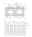
図2は、本発明の液体吐出装置に用いる圧電アクチュエータの他の構造を示すものである。図2(a)によれば、振動板12が第一の圧電セラミック層12aと、第二の圧電セラミック層12bと、これらの間に挟持されるように形成された内部電極層12cとで構成され、振動板12の上に、共通電極15、圧電セラミック層14及び複数の駆動電極16とがこの順に形成されている。なお、図示してないが、共通電極15、内部電極12c、駆動電極16は、それぞれ駆動回路(不図示)に接続されている。
FIG. 2 shows another structure of the piezoelectric actuator used in the liquid ejection apparatus of the present invention. According to FIG. 2A, the
このように、振動板12が2層の圧電セラミック層からなり、その間に導電性部材が挿入されている時、第二の圧電セラミック層12bを分極することが好ましい。その際、内部電極12cと金属である流路部材3との間で駆動回路9を用いて、第二の圧電セラミック層12aを分極することで、繰り返し変位しても変位特性の劣化が少ない圧電アクチュエータ及びこれを用い、長期的な変位の安定性が高い液体吐出装置を提供することができる。
Thus, when the
なお、いずれの方式においても、圧電アクチュエータ11の駆動時においては、駆動回路において、共通電極15と内部電極12cとを短絡させて、共にグランド電位としておくことが好ましい。共通電極15、内部電極12c、駆動電極16は、それぞれ駆動回路(不図示)に接続されている。これにより、振動板12の変形に伴って、圧電効果によって振動板12を挟持する電極12a及び12c間に電位差が生じ、圧電アクチュエータ11の変形に不要な影響を及ぼすことを防止できる。
In any method, when driving the piezoelectric actuator 11, it is preferable to short-circuit the
本発明の液体吐出装置は、圧電インクジェットヘッドの稼働率を低下させることなしに、圧電アクチュエータの変位状態を常に良好な状態に維持することができる。そのため、例えば工業用途の記録装置においては、電子回路や、液晶ディスプレイのカラーフィルタ、有機ELディスプレイの発光セル等を、生産性を低下させることなく、所望の形状に、精度良く形成し続けることができる。また、コンシューマ向けの小型プリンタ等においては、上記の、通常の待機時間以外は待機時間を増加させて動作速度を低下させることなく、文字や画像などを記録し続けることができる。 The liquid ejection device of the present invention can always maintain the displacement state of the piezoelectric actuator in a good state without reducing the operation rate of the piezoelectric ink jet head. Therefore, for example, in a recording apparatus for industrial use, an electronic circuit, a color filter for a liquid crystal display, a light emitting cell for an organic EL display, etc., can be accurately formed in a desired shape without reducing productivity. it can. In addition, in a small printer for consumer use, it is possible to continue recording characters and images without increasing the standby time and reducing the operation speed other than the normal standby time.
図1に示した液体吐出装置を製作した。 The liquid discharge apparatus shown in FIG. 1 was manufactured.
まず、粒径が0.5〜3.0μmのチタン酸ジルコン酸鉛を主成分とする圧電セラミック粉体に対し、アクリル系樹脂エマルジョン、純水、平均粒径が10mmのナイロンボールを添加してボールミルで30時間混合し、得られたスラリーを用いて引き上げ法により厚み30μmのPETフィルム上に、圧電セラミック層4及び振動板2となる厚み35〜37μmのグリーンシートを成形した。
First, an acrylic resin emulsion, pure water, and a nylon ball with an average particle size of 10 mm are added to a piezoelectric ceramic powder mainly composed of lead zirconate titanate having a particle size of 0.5 to 3.0 μm. After mixing for 30 hours by a ball mill, a green sheet having a thickness of 35 to 37 μm to be the piezoelectric
次に、得られたグリーンシートをPETフィルムと共に50×50mmに裁断して2枚1組に分類した後、2枚1組のうち1枚のグリーンシートの略全面には共通電極12cとなる金属ペーストを、スクリーン印刷法によって印刷し、残りの1枚のグリーンシートには金属ペーストを印刷しないで、各グリーンシート及び金属ペーストを防爆型の乾燥機を用いて50℃で20分間乾燥させた。
Next, the obtained green sheet is cut into 50 × 50 mm together with the PET film and classified into a set of two sheets, and then a metal that becomes the
なお、金属ペーストには、平均粒径が2〜4μmの銀粉末とパラジウム粉末を7対3の比率で混合したものを用いた。 The metal paste used was a mixture of silver powder and palladium powder having an average particle diameter of 2 to 4 μm in a ratio of 7 to 3.
そして、上記金属ペーストを印刷した面に、他の1枚のグリーンシートの位置を揃えて重ねあわせた後、60℃の温度で5MPaの圧力を加えながら60秒間保持することにより熱圧着してグリーンシートの積層体を形成した。しかる後、予め形成したスルーホール内に金属ペーストを充填し、乾燥機中で100〜300℃まで毎時8℃の昇温レートで25時間加熱して脱脂した後、室温まで冷却し、さらに焼成炉でピーク温度1100℃で2時間保持して焼成し、振動板2および圧電セラミック層4の厚みがそれぞれ20μmである積層圧電セラミック板を得た。
And after aligning the position of the other one green sheet on the printed surface of the above metal paste, it is thermocompression bonded by holding for 60 seconds while applying a pressure of 5 MPa at a temperature of 60 ° C. A laminate of sheets was formed. After that, a metal paste is filled in a pre-formed through hole, degreased by heating at 100 ° C. to 300 ° C. at a heating rate of 8 ° C. per hour for 25 hours, cooled to room temperature, and further a firing furnace And firing at a peak temperature of 1100 ° C. for 2 hours to obtain a laminated piezoelectric ceramic plate in which the diaphragm 2 and the piezoelectric
次に、上記積層圧電セラミック板の表面に、駆動電極6を金属ペーストで印刷し、ピーク温度800℃の連続炉を30分で通過させて焼き付けした後、ダイシングソーで外辺を切断して外形を33mm×12mmに揃えた。 Next, the driving electrode 6 is printed on the surface of the laminated piezoelectric ceramic plate with a metal paste, and is baked by passing through a continuous furnace having a peak temperature of 800 ° C. in 30 minutes, and then the outer edge is cut with a dicing saw. Were aligned to 33 mm × 12 mm.
しかる後、駆動電極6を形成した面を基台に対向させて設置し、端面をマスクした状態でスパッタリング装置に投入し、圧電セラミック4の表面にかけて、Pd、Cu及びAuを順次成膜し、総厚み約1μmの下面電極5を形成し、本発明の圧電アクチュエータ1を作製した。
After that, the surface on which the drive electrode 6 is formed is placed facing the base, and the end surface is masked and put into a sputtering apparatus, and Pd, Cu and Au are sequentially formed on the surface of the
なお、上記圧電アクチュエータ1には254μmピッチで1列あたり90個の駆動電極25を長手方向に平行に2列にわたって形成している。 The piezoelectric actuator 1 is formed with 90 drive electrodes 25 per row at a pitch of 254 μm in two rows parallel to the longitudinal direction.
一方、厚み100μmのステンレス箔に、長さ2mm、幅0.18mmの液体加圧室3aを、金型プレス法を用いた打ち抜き加工によって形成し、さらに該液体加圧室3aに連通する流路及び液体吐出口8をそれぞれエッチングや金型プレスを用いた打ち抜き加工によって形成した厚み100μm及び40μmのステンレス箔を接着剤を介して貼り合わせることにより流路部材3を形成した。
On the other hand, a
次に、上記圧電アクチュエータ1と、振動板2とを接着剤によって接合し、さらに圧電アクチュエータ1の表面において、各駆動電極6と、共通電極4から上記スルーホール内に充填された電極材の露出部とを、フレキ回路を介して駆動回路9に接合し、インクジェットヘッドを得た。なお、下面電極3bは振動板1と電気的に接続しており、共に駆動回路9のグランド電位に接続されて使用される。
Next, the piezoelectric actuator 1 and the diaphragm 2 are joined together with an adhesive, and on the surface of the piezoelectric actuator 1, the drive electrodes 6 and the electrode material filled in the through holes from the
ここで複数のインクジェットヘッドを作製し、それぞれ駆動回路9より各駆動電極6に、信号を連続して印加し、圧電アクチュエータ1の表面から、各駆動電極6において、撓みによる縦方向の振動を、レーザードップラー振動系によって観測し、圧電アクチュエータ1の変位を測定した。 Here, a plurality of ink jet heads are produced, and signals are continuously applied from the drive circuit 9 to the drive electrodes 6, and vertical vibrations due to bending are applied to the drive electrodes 6 from the surface of the piezoelectric actuator 1. Observation was made with a laser Doppler vibration system, and the displacement of the piezoelectric actuator 1 was measured.
なお、長期耐久試験は、駆動電圧25Vで駆動周波数10kHzで連続印加を行った。 In the long-term durability test, continuous application was performed at a driving frequency of 25 kHz and a driving frequency of 10 kHz.
そして、1億回の連続駆動ごとに、振動板2に、共通電極5と下面電極21を遮断して、−25Vの電圧を印加し、分極処理を実施した場合と、実施しなかった場合の両方で変位を測定し、100億回の駆動回数後の変位の変化を比較した。 And every 100 million times of continuous drive, when the common electrode 5 and the lower surface electrode 21 are interrupted and a voltage of −25 V is applied to the diaphragm 2 and the polarization process is performed, and when the polarization process is not performed Displacement was measured at both, and the change in displacement after 10 billion drive cycles was compared.
本発明による振動板2への逆分極処理を施すことにより、100億回の駆動回数に対して、平均変位の劣化は5%以下に抑制することができた。それに対して逆分極処理しなかった場合は平均変位の劣化は−30%となった。 By applying the reverse polarization process to the diaphragm 2 according to the present invention, it was possible to suppress the deterioration of the average displacement to 5% or less with respect to the drive count of 10 billion times. On the other hand, when the reverse polarization treatment was not performed, the average displacement was -30%.
1、11・・・圧電アクチュエータ
2、12・・・振動板
3・・・流路部材
3a・・・液体加圧室
3b・・・隔壁
4、14・・・共通電極
5、15・・・圧電セラミック層
6、16・・・駆動電極
7、17・・・変位素子
7a・・・変位領域
8・・・液体吐出口
9・・・駆動回路
12a・・・第一の圧電セラミック層
12b・・・第二の圧電セラミック層
12c・・・内部電極層
DESCRIPTION OF SYMBOLS 1, 11 ...
Claims (5)
(2)圧電セラミック層を一対の電極層で挟持してなる圧電素子が、圧電セラミック層からなる振動板の上に設けられてなり、前記一対の電極層に電界を印加して前記圧電素子を変形させることで、前記振動板の一部を含む前記圧電素子全体が変形する圧電アクチュエータと、
を有し、前記圧電アクチュエータの変形によって前記液体加圧室の容積を増減させることで、前記液体加圧室の液体を、前記液体吐出口を通して液滴として吐出させる液体吐出装置であって、
前記流路部材が導電性材料からなり、前記流路部材と前記電極層との間に電圧を加えることで、前記圧電セラミック層の分極方向と反対の方向に、前記振動板の少なくとも一部を分極してなることを特徴とする液体吐出装置。 (1) a flow path member including a liquid pressurizing chamber filled with a liquid and a liquid discharge port communicating with the liquid pressurizing chamber;
(2) A piezoelectric element formed by sandwiching a piezoelectric ceramic layer between a pair of electrode layers is provided on a diaphragm made of a piezoelectric ceramic layer, and an electric field is applied to the pair of electrode layers to A piezoelectric actuator that deforms the entire piezoelectric element including a part of the diaphragm by deforming;
A liquid ejecting apparatus for ejecting the liquid in the liquid pressurizing chamber as droplets through the liquid ejecting port by increasing or decreasing the volume of the liquid pressurizing chamber by deformation of the piezoelectric actuator,
The flow path member is made of a conductive material, and by applying a voltage between the flow path member and the electrode layer, at least a part of the diaphragm is placed in a direction opposite to the polarization direction of the piezoelectric ceramic layer. A liquid ejection apparatus characterized by being polarized.
5. The liquid pressurizing chamber is filled with a conductive liquid, and the liquid filled in the liquid pressurizing chamber is used as one electrode for polarization of the diaphragm. The liquid discharge apparatus according to any one of the above.
Priority Applications (1)
| Application Number | Priority Date | Filing Date | Title |
|---|---|---|---|
| JP2005093941A JP4698263B2 (en) | 2005-03-29 | 2005-03-29 | Liquid ejection device |
Applications Claiming Priority (1)
| Application Number | Priority Date | Filing Date | Title |
|---|---|---|---|
| JP2005093941A JP4698263B2 (en) | 2005-03-29 | 2005-03-29 | Liquid ejection device |
Publications (3)
| Publication Number | Publication Date |
|---|---|
| JP2006272702A true JP2006272702A (en) | 2006-10-12 |
| JP2006272702A5 JP2006272702A5 (en) | 2007-08-02 |
| JP4698263B2 JP4698263B2 (en) | 2011-06-08 |
Family
ID=37207911
Family Applications (1)
| Application Number | Title | Priority Date | Filing Date |
|---|---|---|---|
| JP2005093941A Expired - Fee Related JP4698263B2 (en) | 2005-03-29 | 2005-03-29 | Liquid ejection device |
Country Status (1)
| Country | Link |
|---|---|
| JP (1) | JP4698263B2 (en) |
Cited By (4)
| Publication number | Priority date | Publication date | Assignee | Title |
|---|---|---|---|---|
| JP2008100377A (en) * | 2006-10-17 | 2008-05-01 | Brother Ind Ltd | Recording head, its inspecting method and its manufacturing method |
| JP2010021512A (en) * | 2008-01-30 | 2010-01-28 | Ngk Insulators Ltd | Piezoelectric/electrostrictive film element, and method of manufacturing the same |
| WO2018002648A1 (en) * | 2016-06-30 | 2018-01-04 | Xaar Technology Limited | Poling of a piezoelectric thin film element in a preferred electric field driving direction |
| JP2019039960A (en) * | 2017-08-22 | 2019-03-14 | 株式会社デンソー | Variable focus mirror system |
Citations (1)
| Publication number | Priority date | Publication date | Assignee | Title |
|---|---|---|---|---|
| JP2004328973A (en) * | 2003-04-28 | 2004-11-18 | Kyocera Corp | Highly integrated piezoelectric actuator and ink jet recording head provided with actuator |
-
2005
- 2005-03-29 JP JP2005093941A patent/JP4698263B2/en not_active Expired - Fee Related
Patent Citations (1)
| Publication number | Priority date | Publication date | Assignee | Title |
|---|---|---|---|---|
| JP2004328973A (en) * | 2003-04-28 | 2004-11-18 | Kyocera Corp | Highly integrated piezoelectric actuator and ink jet recording head provided with actuator |
Cited By (4)
| Publication number | Priority date | Publication date | Assignee | Title |
|---|---|---|---|---|
| JP2008100377A (en) * | 2006-10-17 | 2008-05-01 | Brother Ind Ltd | Recording head, its inspecting method and its manufacturing method |
| JP2010021512A (en) * | 2008-01-30 | 2010-01-28 | Ngk Insulators Ltd | Piezoelectric/electrostrictive film element, and method of manufacturing the same |
| WO2018002648A1 (en) * | 2016-06-30 | 2018-01-04 | Xaar Technology Limited | Poling of a piezoelectric thin film element in a preferred electric field driving direction |
| JP2019039960A (en) * | 2017-08-22 | 2019-03-14 | 株式会社デンソー | Variable focus mirror system |
Also Published As
| Publication number | Publication date |
|---|---|
| JP4698263B2 (en) | 2011-06-08 |
Similar Documents
| Publication | Publication Date | Title |
|---|---|---|
| JP2006231909A (en) | Liquid jetting head and liquid jetting apparatus | |
| US6739704B2 (en) | Piezoelectric transducer and ink ejector using piezoelectric transducer | |
| JP4594262B2 (en) | Dispensing device | |
| JP4698263B2 (en) | Liquid ejection device | |
| JP4563786B2 (en) | Liquid ejecting apparatus and driving method thereof | |
| JP4777639B2 (en) | Piezoelectric actuator, method for regenerating the same, and liquid ejection device | |
| JP2004096068A (en) | Piezoelectric element, piezoelectric actuator, and liquid injection head | |
| JP4917426B2 (en) | Liquid ejection device | |
| JP4580201B2 (en) | Piezoelectric element regeneration method and liquid ejection device | |
| JP2004262242A (en) | Print head and printing method | |
| JP2006156894A (en) | Piezoelectric actuator, piezoelectric pump and ink jet head | |
| JP2000218780A (en) | Ink-jet printer head | |
| JP2012076387A (en) | Liquid injection head, liquid injection device, and piezoelectric actuator | |
| JP2005035295A (en) | Driving method for piezoelectric ink jet head | |
| JP2004336981A (en) | Piezoelectric actuator and ink jet recording head | |
| JP2004351879A (en) | Piezoelectric inkjet head | |
| JP4583117B2 (en) | Liquid ejection device and inkjet head | |
| JP4847180B2 (en) | Piezoelectric actuator driving method and piezoelectric actuator unit | |
| JP4456357B2 (en) | Piezoelectric actuator and inkjet recording head | |
| JP4594060B2 (en) | Liquid ejection device | |
| JP2007123585A (en) | Piezoelectric actuator, its manufacturing method and ink jet head | |
| JP2008080622A (en) | Liquid discharge head and liquid discharge device | |
| JP4498035B2 (en) | Printing head and printing method | |
| US20110169378A1 (en) | Actuator apparatus and methods of manufacturing actuator apparatus, liquid ejecting head, and liquid ejecting apparatus | |
| JP2004351878A (en) | Piezoelectric inkjet head |
Legal Events
| Date | Code | Title | Description |
|---|---|---|---|
| A521 | Request for written amendment filed |
Free format text: JAPANESE INTERMEDIATE CODE: A523 Effective date: 20070615 |
|
| A621 | Written request for application examination |
Free format text: JAPANESE INTERMEDIATE CODE: A621 Effective date: 20080118 |
|
| A977 | Report on retrieval |
Free format text: JAPANESE INTERMEDIATE CODE: A971007 Effective date: 20101025 |
|
| A131 | Notification of reasons for refusal |
Free format text: JAPANESE INTERMEDIATE CODE: A131 Effective date: 20101028 |
|
| A521 | Request for written amendment filed |
Free format text: JAPANESE INTERMEDIATE CODE: A523 Effective date: 20101207 |
|
| TRDD | Decision of grant or rejection written | ||
| A01 | Written decision to grant a patent or to grant a registration (utility model) |
Free format text: JAPANESE INTERMEDIATE CODE: A01 Effective date: 20110201 |
|
| A61 | First payment of annual fees (during grant procedure) |
Free format text: JAPANESE INTERMEDIATE CODE: A61 Effective date: 20110301 |
|
| R150 | Certificate of patent or registration of utility model |
Ref document number: 4698263 Country of ref document: JP Free format text: JAPANESE INTERMEDIATE CODE: R150 |
|
| LAPS | Cancellation because of no payment of annual fees |