JP2006271908A - Brush belt type shoe washing machine - Google Patents
Brush belt type shoe washing machine Download PDFInfo
- Publication number
- JP2006271908A JP2006271908A JP2005122895A JP2005122895A JP2006271908A JP 2006271908 A JP2006271908 A JP 2006271908A JP 2005122895 A JP2005122895 A JP 2005122895A JP 2005122895 A JP2005122895 A JP 2005122895A JP 2006271908 A JP2006271908 A JP 2006271908A
- Authority
- JP
- Japan
- Prior art keywords
- brush
- brushes
- shoe
- string
- attached
- Prior art date
- Legal status (The legal status is an assumption and is not a legal conclusion. Google has not performed a legal analysis and makes no representation as to the accuracy of the status listed.)
- Granted
Links
Images


Abstract
Description
この発明は、ベルトにブラシを付けた、靴洗い機に関するものである。The present invention relates to a shoe washer having a brush attached to a belt.
従来、靴を洗う際に、いろいろなタワシやブラシがあった。Conventionally, there have been various scrubbing brushes when washing shoes.
しかし靴の中は洗いずらいため従来のタワシやブラシでは、きれいに洗い落ということは、時間もかかりむづかしかった、とくに爪先の当たる部分は狭くて見えにくく、ひじょうに洗いずらかった、このために多くの人達が靴を洗うのをめんどくさがったり、また嫌がったりする子ども達も多くいた、このために、ついおろそかになり、いやな臭いや水虫などといった病気の原因にもなった。本発明は、これらの不便や問題を除くためにつくられたものである。However, because it is hard to wash in shoes, it was difficult to wash cleanly with conventional scrubbing brushes and brushes, and it was difficult to take a long time. There were many children who were bothered and disliked to wash their shoes, which made them neglected and caused illnesses such as bad smell and athlete's foot. The present invention has been made to eliminate these inconveniences and problems.
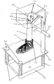
中空軸(1)の下部を図1のように横長にラッパ状につくり、このラッパ状(1)の前下部に車軸(2)を設けて、プ−リ−(3)を取り付ける、この斜め後双方に側プ−リ−(9)、(9)を設け、中空軸(1)の中に車軸(4)を設け、この下に駆動プ−リ−(5)を取り付ける、そして図4、図5に示すように、ブラシベルト(6)に、上ブラシ及び下ブラシを設け、これをこれらプ−リ−(3)、側プ−リ−(9)(9)、駆動プ−リ−(5)以上のプ−リ−に巻いて付けて、後方ブラシ(12)を、後方軸(11)に止める、またリングブラシ部も、リングブラシ取付け前軸(10)に、取り付ける、そしてこれら上ブラシそれぞれに、上紐(35)を通し、車軸(4)に設けた、紐掛けプ−リ−(34))に巻き付ける、そして下ブラシ(20)それぞれも下紐(36)を、通し合って互いに繋ぐ、本発明はこのような特徴のある゛ブラシベルトであるから、これを動かすために、図1に示すように靴洗い台(21)をつくり、これにハンドル(22))、クランク軸(23)ア−ム(24)、アーム(25)、軸(26)、傘歯車(27)、車軸(4)の上に設けた傘歯車(28)、この下に靴乗せ板(30)、この靴乗せ板(30)を支えるバネ(31)、そして靴乗せ板(30)が適当な位置で止まるように設けた、止め板(32)、以上を設ける、本発明は以上のような構成よりなるベルトにブラシを付けた、靴洗い機であります。The lower part of the hollow shaft (1) is formed into a trumpet shape horizontally as shown in FIG. 1, the axle (2) is provided at the front lower part of the trumpet shape (1), and the pulley (3) is attached. Side pulleys (9) and (9) are provided on both rear sides, an axle shaft (4) is provided in the hollow shaft (1), and a drive pulley (5) is attached below this, and FIG. As shown in FIG. 5, the brush belt (6) is provided with an upper brush and a lower brush, which are connected to the pulley (3), side pulley (9) (9), and drive pulley. -(5) Wrapped around the above pulleys, the rear brush (12) is fixed to the rear shaft (11), and the ring brush part is also attached to the ring brush mounting front shaft (10), and Pass the upper string (35) through each of these upper brushes, wrap it around the stringing pulley (34) provided on the axle (4), and Each of the brushes (20) also connects the lower string (36) through each other. Since the present invention is a brush belt having such a feature, as shown in FIG. (21) is formed on the handle (22)), the crankshaft (23) arm (24), the arm (25), the shaft (26), the bevel gear (27), and the axle (4). A bevel gear (28), a shoe rest plate (30), a spring (31) for supporting the shoe rest plate (30), and a shoe rest plate (30) provided so that the shoe rest plate (30) stops at an appropriate position. The board (32) is provided with the above. The present invention is a shoe washer with a brush attached to the belt constituted as described above.
靴乗せ板(30)を手で押さえ、下に押さえたままブラシベルト(6)に靴ををはかせる、靴乗せ板(30)から手を緩め、靴の中に洗剤や水を入れ、靴の甲に当たる部分をつかみ、ハンドル(22)を回す、するとクランク軸(23)、ア−ム(24)、ア−ム(25)の働きで傘歯車(27)車軸(4)の上に設けた傘歯車(28)が右左右左と回り同時に車軸(4)から、駆動プ−リ−(5)に伝わり、上ブラシ及び下ブラシを設けたブラシベルト(6)も、右左右左と、靴のなかでゴシゴシとこすり動くので、靴を前後左右と、靴乗せ板(30)の上を、洗いたい部分へ滑らしながら移動させ、靴の中を素早くきれいに洗えるものであります。Hold the shoe rest plate (30) with your hand, hold the shoe down on the brush belt (6), loosen your hands from the shoe rest plate (30), put detergent or water into the shoe, Grab the part that hits the back and turn the handle (22). Then, the crankshaft (23), the arm (24), and the arm (25) are installed on the bevel gear (27) and the axle (4). The bevel gear (28) is rotated from right to left and right and simultaneously transmitted from the axle (4) to the drive pulley (5), and the brush belt (6) provided with the upper brush and the lower brush is also Because it rubs in the shoe, you can move the shoe back and forth, right and left, and on the shoe rest plate (30) while sliding it to the part you want to wash, so you can quickly and cleanly wash the shoe.
以下、本発明の実施例について説明する。
中空軸(1)の下部を横長にラッパ状につくり、このラッパ状(1)の前下部に、車軸(2)を設け、これにプ−リ−(3)を取り付ける、この斜め後双方に、靴の中の側部を洗いやすくするため、また右片方の靴、左片方の靴、左右どちらの靴でも洗えるよぅに側プ−リ−(9)(9)設ける、そして中空軸(1)の中に車軸(4)を設け、これに駆動プ−リ−(5)を、取り付ける、またこの中空軸(1)の後方に、図3に示すよぅに作動口(18)と、作動口(17)を前と後に設け、後方軸(11)を、この作動口(17)を通して車軸(4)に取り付ける、同じくリングブラシ部取付け軸(10)も、前作動口(18)を通し、車軸(4)に取り付ける、そしてプ−リ−(3)、側プ−リー(9)(9)、駆動プ−リ−(5)、以上のプ−リ−の下に、下ブラシ滑り歯車カバ−(7)を設け、ベルトにブラシを付けた、ブラシベルト(6)に、上ブラシ及び下ブラシを設け、これを、これらプ−リ−(3)、側プ−リ−(9)(9)駆動プ−リ−(5)に巻いて取付けて、後方ブラシ(12)を、後方軸(11)止める、そしてリングブラシ部(33)も、リングブラシ取付け軸(10)に取り付ける、また上ブラシ(13)上ブラシ(14)(14)上ブラシ(15)(15)上ブラシ(16)(16)に、上紐通し穴(37)を開けてそして、これら上ブラシそれぞれに、上紐(35)を、通して中空軸(1)の紐通し穴(40)を通し、車軸(4)に設けた紐巻きプ−リ−(34)に、図4に示すよぅに取付ける、そして下ブラシ(20)それぞれも、図5に示すよぅに、下紐通し穴(38)に、下紐(36)を、通しあい、互いに繋ぐ、なお上紐(35)及び下紐(36))を、各紐穴を通して繋ぐことによって上ブラシ及び下ブラシそれぞれが、どんな動きにも安定したバランスを保って動くことができるよぅにしたものである。本発明はこのような特徴のあるブラシベルト式であるからこれらブラシを動かすために、また靴洗い作業がしやすくするために、靴洗い台(21)をつくり、これにハンドル(22)を設け、クランク軸(23)、アーム(24)、アーム(25)、軸(26)、傘歯車(27)、傘歯車(28)、そしてこれらの下に、靴乗せ板(30)、そして靴乗せ板(30)を支えるバネ(31)靴乗せ板(30)が適当な位置で止まるように設けた止め板(32)、以上を設けた靴洗い機。本発明は以上のような講造でこれを使用する際は、靴乗せ板(30)を手押さえ、下に押さえたままブラシベルト(6)に靴をはかせる、靴乗せ板(30)から手ゆるめ、靴の中に洗剤や水を入れて、靴の甲になる部をつかみハンドル(22)を回す、クランク軸(23)、ア−ム−(24)、ア−ム−(25)の働きで、傘歯車(27)そして車軸(4)の、上に設けた歯車(28)が、右左右左と回り、同時に車軸(4)や駆動プ−リ−(5)に伝わり上ブラシ及び下ブラシを設けたブラシベルト(6)も、右左右左と靴の中でこすりながら回るので、靴を前後左右と靴の乗せ板(30)の上を、洗いたい部分へ滑らしながら移動させる、同時に靴の中底も図3に示すように、下ブラシ(20)それぞれと、靴乗せ板(30)との間に、バネ(31)の力で挟まれて、洗えるようにしたものであります、したがって本発明の下ブラシ(20)それぞれは、靴の中底を洗うために設けたものである、また上ブラシ(13)、(14)(14)は、爪上や指上部を洗えるよぅに、設けられたブラシである、上ブラシ(15)(15)は、指上や足の甲に当たる部分を、洗えるよぅに設けたブラシである、上ブラシ(16)(16)は、その甲と、この側を洗えるよぅに設けたものである、またリングブラシ部(33)はその甲の上部と、この周囲を洗えるよぅに設けたものである、そして後方ブラシ(12)は、踵部と、この側を洗うために設けたブラシである、以上のよぅな構成であるから、ブラシベルト(6)の動きも一回転するものではないから靴を洗う際に靴紐などが靴の中に入っても、ブラシベルトに絡まったりすることなく洗えるものであります、また本発明は従来のタワシやブラシ同様、靴を洗う際に、水や洗剤水を常に使用しますので、ブラシやベルトなどに摩擦といったものがなく安全なものであります、また本発明は下ブラシ滑り歯車カバ−(7)を、これらプ−リ−(3)、側プ−リ−(9)(9))、駆動プ−リ−(5)、以上のプ−リ−を下から塞ぐよぅにして取付けてありますので、これが安全カバ−の役目にもなるようになされたものでありますので、危険といったものがなく安全なもので誰でも使用ができるものであります。つぎに図6に示すよぅに、これらのブラシの動きを、よりスム−ズに動かすために、ロ−ラ−(19)を、これらの上ブラシ及び下ブラシそれぞれに設けたものであります、したがって本発明は、ブラシベルトをより効果的に動かすために、靴洗い台(21)の上部に小型モ−タ−などを取りつけて動かすよぅにすれば、両手をうまく使って洗うことができ、よりまた短時間に洗えるよぅになるので、より便利になるというものであります。つぎに本発明は、従来のタワシ同様、水を常に使用しますので、図7に示すよぅに、給水口(44)を設け、これにホ−スを繋ぎ、洗ったり濯いだりもできるものであります、したがって図7に示すよぅな形にして、手持ち式につくり、これにバッテリ−(43)及び小型モ−タ−(42)を中に取付け、移動ができて、靴の外面も洗えるよぅにできるものであります、さらにこの中に小さなミニポンプを設け、水が必要時に水を吸い込みができるようにして、お風呂の残り湯などを使って、靴を洗ったり、濯いだりができるものであります、また本発明は図7に示すよぅな、構造で、このような形にすれば、従来のタワシのよぅにゴシゴシと力を入れてこすらなくても、スイッチを入れ、手で押さえたまま、洗ったり濯いだりが簡単にできるものであります、たとえばお風呂場の床やタイルなども楽に洗いながら、流すことができるものであります。Examples of the present invention will be described below.
The lower part of the hollow shaft (1) is formed horizontally in a trumpet shape, the axle (2) is provided at the front lower part of the trumpet shape (1), and the pulley (3) is attached to both of the rear and rear sides. In order to make it easier to wash the side of the shoe, the right side shoe, the left side shoe, and the left and right side shoes can be washed. ) Is provided with an axle (4), to which a drive pulley (5) is attached, and behind this hollow shaft (1), an operating port (18) as shown in FIG. An opening (17) is provided at the front and rear, and the rear shaft (11) is attached to the axle (4) through the operating port (17). Similarly, the ring brush part mounting shaft (10) is also passed through the front operating port (18). Attached to the axle (4), and the pulley (3), side pulley (9) (9), drive pulley (5), A lower brush sliding gear cover (7) is provided under the pulley of the belt, and a brush is attached to the belt. An upper brush and a lower brush are provided on the brush belt (6). -(3), side pulley (9), (9) wound around the drive pulley (5) and attached, the rear brush (12) is fixed to the rear shaft (11), and the ring brush portion (33) ) Is also attached to the ring brush mounting shaft (10), and the upper brush (13), upper brush (14), (14) upper brush (15), (15) upper brush (16), (16), upper string through hole ( 37) is opened, and the upper string (35) is passed through each of the upper brushes, the string passage hole (40) of the hollow shaft (1) is passed through, and the string winding pulley provided on the axle (4). (34) is attached as shown in FIG. 4, and the lower brush (20) is also shown in FIG. Pass the lower string (36) through the lower string through hole (38) and connect them to each other, and connect the upper string (35) and the lower string (36)) through the respective string holes. Each of the lower brushes is designed to move with a stable balance for any movement. Since the present invention is a brush belt type having such characteristics, in order to move these brushes and to facilitate the shoe washing operation, a shoe wash basin (21) is formed and a handle (22) is provided thereon. The crankshaft (23), the arm (24), the arm (25), the shaft (26), the bevel gear (27), the bevel gear (28), and under these, the shoe rest plate (30) and the shoe rest A spring (31) for supporting the plate (30), a stop plate (32) provided so that the shoe rest plate (30) stops at an appropriate position, and a shoe washing machine provided with the above. When the present invention is used in the course as described above, the shoe rest plate (30) is held down, and the shoe is put on the brush belt (6) while being held down. Loosen hands, put detergent or water into the shoes, grab the part that becomes the back of the shoes, turn the handle (22), crankshaft (23), arm (24), arm (25) As a result, the bevel gear (27) and the gear (28) provided on the axle (4) rotate to the right, left, and left, and are simultaneously transmitted to the axle (4) and the drive pulley (5). Also, the brush belt (6) provided with the lower brush also rotates while rubbing in the right, left, right and left and the shoes, so the shoes are moved while sliding on the front and rear, left and right and the shoe rest plate (30) to the part to be washed. At the same time, as shown in FIG. 3, the insole of the shoe is between each lower brush (20) and the shoe rest plate (30). The lower brush (20) of the present invention is provided for washing the insole of the shoe, and the upper brush (13). ), (14) and (14) can wash the top of the nail and the upper part of the finger, and the upper brushes (15) and (15) which are provided brushes can wash the part hitting the top of the finger and the back of the foot. The upper brushes (16) and (16), which are provided brushes, are provided so as to wash the back and this side, and the ring brush part (33) can wash the upper part and the surroundings of the back. Since the rear brush (12) is a brush provided to wash the heel portion and this side, the rear brush (12) has the above-described more favorable configuration, so the movement of the brush belt (6) is also one. Since it is not a rotating one, shoelaces are Even if it enters, it can be washed without getting entangled with the brush belt, and since the present invention always uses water and detergent water when washing shoes like conventional scrubbing brushes, brushes, belts etc. In the present invention, the lower brush sliding gear cover (7) is driven by the pulley (3), the side pulley (9) (9)), and the drive. The pulley (5) is installed so as to close the above pulley from the bottom, so it is designed to serve as a safety cover, so there is no danger and it is safe. Anyone can use it. Next, as shown in FIG. 6, in order to move the movement of these brushes more smoothly, rollers (19) are provided on each of the upper brush and the lower brush. In the present invention, in order to move the brush belt more effectively, if a small motor or the like is attached to the upper part of the shoe wash basin (21) and moved, both hands can be washed well, Also, it can be washed in a short time, making it more convenient. Next, since the present invention always uses water as in the case of the conventional scrubber, as shown in FIG. 7, a water supply port (44) is provided, and a hose can be connected to this so that it can be washed and rinsed. Therefore, it is made as a handy type as shown in FIG. 7, and a battery (43) and a small motor (42) can be mounted and moved inside, and the outer surface of the shoe can be washed. In addition, a small mini-pump is installed in this so that water can be sucked in when needed, and the shoes can be washed and rinsed using remaining hot water from the bath. In addition, the present invention has a structure as shown in FIG. 7. With such a shape, the switch is turned on and pressed by hand even if it is not rubbed with the force of a conventional scrubber. Easy to wash and rinse What is it you, for example, while such is also easy to wash your bathroom floors and tile, it is proposed that can be made to flow.
したがって本発明は、以上のような構造であるから運動靴や作業靴などの中に染みついた汗や油泥などの汚れも爪先から踵まれ、きれいに早く、しかも短時間で洗いおっとすことができるので便利であります、このために靴の中が清潔になり、水虫といた病気も数少なくなると思います、また本発明は図7に示すよぅに、手持ち形すれば、色々な場所で色々な場所を洗ったり濯いだりができるものであり便利であります。Therefore, since the present invention has the structure as described above, dirt such as sweat and oil mud that has soaked into athletic shoes and work shoes can be swollen from the toes, so that it can be cleaned quickly and quickly. Conveniently, this will clean the inside of the shoe and reduce the number of diseases caused by athlete's foot. Also, as shown in Fig. 7, the present invention can wash various places in various places if it is hand-held. It is convenient because it can be rinsed and rinsed.
1中空軸 16上ブラシ 31バネ
2車軸 17作動口 32止め板
3プ−リ− 18前作動口 33リングブラシ
4車軸 19ロ−ラ− 34紐掛けプ−リ−
5駆動プ−リ− 20下ブラシ 35上紐
6ブラシベルト 21靴洗い台 36下紐
7歯車カバ− 22ハンドル 37上紐通し穴
8車軸 23クランク軸 38下紐通し穴
9側プ−リ− 24ア−ム 39ベルト支え板
10リングブラシ取付け軸 25ア−ム 40紐通し穴
11後方軸 26軸 41電気スイッチ
12後方ブラシ 27傘歯車 42モ−タ−
13上ブラシ 28傘歯車 43バッテリ−
14上ブラシ 29歯車カバ− 44給水パイプ
15上ブラシ 30靴乗せ板 45排水口1
5
13
14
Claims (1)
Priority Applications (1)
| Application Number | Priority Date | Filing Date | Title |
|---|---|---|---|
| JP2005122895A JP4551269B2 (en) | 2005-03-25 | 2005-03-25 | Brush belt type shoe washer |
Applications Claiming Priority (1)
| Application Number | Priority Date | Filing Date | Title |
|---|---|---|---|
| JP2005122895A JP4551269B2 (en) | 2005-03-25 | 2005-03-25 | Brush belt type shoe washer |
Publications (2)
| Publication Number | Publication Date |
|---|---|
| JP2006271908A true JP2006271908A (en) | 2006-10-12 |
| JP4551269B2 JP4551269B2 (en) | 2010-09-22 |
Family
ID=37207201
Family Applications (1)
| Application Number | Title | Priority Date | Filing Date |
|---|---|---|---|
| JP2005122895A Expired - Fee Related JP4551269B2 (en) | 2005-03-25 | 2005-03-25 | Brush belt type shoe washer |
Country Status (1)
| Country | Link |
|---|---|
| JP (1) | JP4551269B2 (en) |
Cited By (6)
| Publication number | Priority date | Publication date | Assignee | Title |
|---|---|---|---|---|
| KR200468278Y1 (en) * | 2011-08-12 | 2013-08-02 | 유재섭 | washing brush of shoes |
| KR101493132B1 (en) | 2012-12-03 | 2015-02-13 | 이영우 | an automated washing method for sports shoes |
| CN104586340A (en) * | 2015-02-02 | 2015-05-06 | 李泽晨 | Shoe sole wiping device |
| CN109330540A (en) * | 2018-12-17 | 2019-02-15 | 温州大学 | Inertial centrifugal shoe rack means for shoe washing machine |
| CN110959053A (en) * | 2017-07-27 | 2020-04-03 | 青岛海尔洗衣机有限公司 | Shoe washing device |
| JP2021013707A (en) * | 2019-07-16 | 2021-02-12 | 山崎産業株式会社 | Cleaning tool |
Citations (5)
| Publication number | Priority date | Publication date | Assignee | Title |
|---|---|---|---|---|
| US3387311A (en) * | 1964-07-24 | 1968-06-11 | Doskocil Fernand | Shoe cleaning machine |
| JPS57188229A (en) * | 1981-05-13 | 1982-11-19 | Kanji Nagaoka | Cleaner |
| JPS585661U (en) * | 1981-07-06 | 1983-01-14 | 角田 敏忠 | belt brush type shoe washing machine |
| JPH01153174U (en) * | 1988-04-15 | 1989-10-23 | ||
| JPH0595462U (en) * | 1992-05-22 | 1993-12-27 | 株式会社ジーティーシー | Zuk shoe washer |
-
2005
- 2005-03-25 JP JP2005122895A patent/JP4551269B2/en not_active Expired - Fee Related
Patent Citations (5)
| Publication number | Priority date | Publication date | Assignee | Title |
|---|---|---|---|---|
| US3387311A (en) * | 1964-07-24 | 1968-06-11 | Doskocil Fernand | Shoe cleaning machine |
| JPS57188229A (en) * | 1981-05-13 | 1982-11-19 | Kanji Nagaoka | Cleaner |
| JPS585661U (en) * | 1981-07-06 | 1983-01-14 | 角田 敏忠 | belt brush type shoe washing machine |
| JPH01153174U (en) * | 1988-04-15 | 1989-10-23 | ||
| JPH0595462U (en) * | 1992-05-22 | 1993-12-27 | 株式会社ジーティーシー | Zuk shoe washer |
Cited By (7)
| Publication number | Priority date | Publication date | Assignee | Title |
|---|---|---|---|---|
| KR200468278Y1 (en) * | 2011-08-12 | 2013-08-02 | 유재섭 | washing brush of shoes |
| KR101493132B1 (en) | 2012-12-03 | 2015-02-13 | 이영우 | an automated washing method for sports shoes |
| CN104586340A (en) * | 2015-02-02 | 2015-05-06 | 李泽晨 | Shoe sole wiping device |
| CN110959053A (en) * | 2017-07-27 | 2020-04-03 | 青岛海尔洗衣机有限公司 | Shoe washing device |
| CN109330540A (en) * | 2018-12-17 | 2019-02-15 | 温州大学 | Inertial centrifugal shoe rack means for shoe washing machine |
| CN109330540B (en) * | 2018-12-17 | 2024-01-30 | 温州大学 | Inertial centrifugal shoe rack device for shoe washer |
| JP2021013707A (en) * | 2019-07-16 | 2021-02-12 | 山崎産業株式会社 | Cleaning tool |
Also Published As
| Publication number | Publication date |
|---|---|
| JP4551269B2 (en) | 2010-09-22 |
Similar Documents
| Publication | Publication Date | Title |
|---|---|---|
| JP2006271908A (en) | Brush belt type shoe washing machine | |
| KR100960707B1 (en) | Automatic bathing apparatus | |
| CN104161492B (en) | Brush wheel shoe washing machine | |
| WO2018040189A1 (en) | Drum washing machine | |
| KR20130117606A (en) | Automatic washing machine for shoes | |
| KR101667911B1 (en) | Shoes washing set | |
| WO2010072046A1 (en) | Multifunctional washing machine with clothes brushing function | |
| KR101059224B1 (en) | Shoe floor scrubber | |
| CN108937811A (en) | One kind, which is washed, dries shoes all-in-one machine | |
| CN103271712A (en) | Automatic carpet | |
| JP2018051038A (en) | Attachment for shoe washing and shoe washing device | |
| KR20100052715A (en) | Shoes box | |
| JPH0548154B2 (en) | ||
| KR200342808Y1 (en) | Washing brush for feet | |
| KR101012992B1 (en) | Washing auxiliary tool | |
| JPS5929643Y2 (en) | shoe cleaning machine | |
| KR20140064538A (en) | Manual type washer | |
| CN215937288U (en) | Shoe washing machine | |
| CN217885958U (en) | Horizontal semi-automatic rubbing type shoe washing machine | |
| KR200441418Y1 (en) | Motor Driven Sports Shoes Washing Machine | |
| CN211355342U (en) | Drum-type shoe washing machine | |
| JP2614414B2 (en) | Hand washer | |
| KR200330233Y1 (en) | The inside scrub brush for shoes | |
| KR101330139B1 (en) | Cleaning device for outsole side of sneakers | |
| JP3126759U (en) | Cleaning tool |
Legal Events
| Date | Code | Title | Description |
|---|---|---|---|
| A621 | Written request for application examination |
Free format text: JAPANESE INTERMEDIATE CODE: A621 Effective date: 20071129 |
|
| A977 | Report on retrieval |
Effective date: 20100216 Free format text: JAPANESE INTERMEDIATE CODE: A971007 |
|
| A131 | Notification of reasons for refusal |
Free format text: JAPANESE INTERMEDIATE CODE: A131 Effective date: 20100309 |
|
| RD02 | Notification of acceptance of power of attorney |
Free format text: JAPANESE INTERMEDIATE CODE: A7422 Effective date: 20100430 |
|
| A521 | Written amendment |
Effective date: 20100506 Free format text: JAPANESE INTERMEDIATE CODE: A523 |
|
| A521 | Written amendment |
Effective date: 20100430 Free format text: JAPANESE INTERMEDIATE CODE: A821 |
|
| TRDD | Decision of grant or rejection written | ||
| A01 | Written decision to grant a patent or to grant a registration (utility model) |
Effective date: 20100702 Free format text: JAPANESE INTERMEDIATE CODE: A01 |
|
| A01 | Written decision to grant a patent or to grant a registration (utility model) |
Free format text: JAPANESE INTERMEDIATE CODE: A01 |
|
| A61 | First payment of annual fees (during grant procedure) |
Effective date: 20100709 Free format text: JAPANESE INTERMEDIATE CODE: A61 |
|
| R150 | Certificate of patent (=grant) or registration of utility model |
Free format text: JAPANESE INTERMEDIATE CODE: R150 |
|
| FPAY | Renewal fee payment (prs date is renewal date of database) |
Free format text: PAYMENT UNTIL: 20130716 Year of fee payment: 3 |
|
| LAPS | Cancellation because of no payment of annual fees |