JP2006267714A - Illuminating device and projection type video display device - Google Patents
Illuminating device and projection type video display device Download PDFInfo
- Publication number
- JP2006267714A JP2006267714A JP2005087221A JP2005087221A JP2006267714A JP 2006267714 A JP2006267714 A JP 2006267714A JP 2005087221 A JP2005087221 A JP 2005087221A JP 2005087221 A JP2005087221 A JP 2005087221A JP 2006267714 A JP2006267714 A JP 2006267714A
- Authority
- JP
- Japan
- Prior art keywords
- light
- color
- illumination device
- emits
- light source
- Prior art date
- Legal status (The legal status is an assumption and is not a legal conclusion. Google has not performed a legal analysis and makes no representation as to the accuracy of the status listed.)
- Pending
Links
Images


Abstract
Description
この発明は、照明装置及びこの照明装置を用いた投写型映像表示装置に関する。 The present invention relates to a lighting device and a projection display apparatus using the lighting device.
従来より、固体発光素子がアレイ状に配置された光源を用いた照明装置が提案されている(特許文献1参照)。 Conventionally, an illumination device using a light source in which solid-state light emitting elements are arranged in an array has been proposed (see Patent Document 1).
ところで、図8に示すように、LEDがアレイ状に配置された光源100を用い、この光源100からの光を光学部材(例えばレンズなど)101の光入射面に照射することが考えられる。しかしながら、前記光源100における各固体発光素子からの出射光を十分に平行光化することは容易でなく、十分に平行光化できなかった場合には次段の光学部材101の機能を十分に発揮させることはできない。また、前記光学部材101の光入射面が前記光源の発光面よりも小さいと、光の取り込み効率が低下する。
Incidentally, as shown in FIG. 8, it is conceivable to use a
この発明は、上記事情に鑑み、光源の次段に設けられる光学部材の機能を十分に発揮させることができ、また、光源が出射する光の取り込み効率を向上することができる照明装置及びこれを用いた投写型映像表示装置を提供することを目的とする。 In view of the above circumstances, the present invention can sufficiently exhibit the function of an optical member provided at the next stage of the light source, and can improve the efficiency of capturing light emitted from the light source, It is an object of the present invention to provide a projection display apparatus used.
この発明の照明装置は、上記の課題を解決するために、光源と、前記光源から出射された光が入射される光入射面及び前記光が出射される光出射面を有した光学部材と、から成る照明装置において、前記光源は固体発光素子から出射された光を集光するか又は分散角が小さくなるように制御する光学素子を備えており、前記光源はその主光線軸を前記光学部材の光軸に対して傾けて配置されていることを特徴とする。 In order to solve the above problems, the illumination device of the present invention includes a light source, a light incident surface on which light emitted from the light source is incident, and an optical member having a light emission surface from which the light is emitted, The light source includes an optical element that condenses the light emitted from the solid light emitting element or controls the dispersion angle to be small, and the light source has its principal ray axis as the optical member. It is arranged to be inclined with respect to the optical axis.
上記の構成であれば、光源はその主光線軸を前記光学部材の光軸に対して傾けて配置されているので、光源が出射する光の取り込み効率を向上することができる。 If it is said structure, since the light source is arrange | positioned inclining the principal ray axis with respect to the optical axis of the said optical member, the capture efficiency of the light which a light source radiate | emits can be improved.
上記構成の照明装置において、前記光源からの光は、前記光入射面と前記光軸とが交わる点を中心とした小領域に集光されるのがよい。これによれば、光源の次段に設けられる光学部材の機能を十分に発揮させることができる。 In the illuminating device having the above configuration, the light from the light source may be collected in a small region centered on a point where the light incident surface and the optical axis intersect. According to this, the function of the optical member provided at the next stage of the light source can be sufficiently exhibited.
これら構成の照明装置において、前記光学部材の光入射面は、平面、曲面、又は凹凸面であってもよい。また、これら構成の照明装置において、前記光学部材はレンズであってもよし、或いは受けた光を重畳して出射するロッドインテグレータであってもよい。前記レンズはコリメータレンズであってもよい。前記ロッドインテグレータは光出射面よりも光入射面が小さいテーパ型のロッドインテグレータであってもよい。 In the illumination device having these configurations, the light incident surface of the optical member may be a flat surface, a curved surface, or an uneven surface. In the illumination device having these configurations, the optical member may be a lens or a rod integrator that superimposes and emits received light. The lens may be a collimator lens. The rod integrator may be a tapered rod integrator having a light incident surface smaller than that of the light emitting surface.
これら構成の照明装置において、前記光源を複数有し、各々の光源の主光線軸は互いに非平行に設定されていてもよい。 The illuminating device having these configurations may include a plurality of the light sources, and the principal ray axes of the light sources may be set non-parallel to each other.
これら構成の照明装置において、前記光源は、所定の色光を出射する色光源であってもよい(以下、この項において第1照明装置という)。或いは、これら構成の照明装置において、前記光源は白色光源であってもよい(以下、この項において第2照明装置という)。 In the illumination device having these configurations, the light source may be a color light source that emits predetermined color light (hereinafter referred to as a first illumination device in this section). Alternatively, in the illumination device having these configurations, the light source may be a white light source (hereinafter referred to as a second illumination device in this section).
また、前記複数の光源を有する照明装置において、前記複数の光源は異なる色光を出射してもよい。かかる構成において、前記複数の光源として、赤色光を出射する光源と、青色光を出射する光源と、緑色光を出射する光源と、を有していてもよい。(以下、この項において第3照明装置という)。 In the illumination device having the plurality of light sources, the plurality of light sources may emit different color lights. In such a configuration, the plurality of light sources may include a light source that emits red light, a light source that emits blue light, and a light source that emits green light. (Hereinafter referred to as the third lighting device in this section).
また、この発明の照明装置は、第1色光を出射する第1照明装置と、第2色光を出射する第1照明装置と、第3色光を出射する第1照明装置と、各照明装置からの各色光を略同一方向に導く光学部材と、から成ることを特徴とする。また、かかる構成において、第1色光は赤色であり、第2色光は青色であり、第3色光は緑色であってもよい(以下、この項において第4照明装置という)。 Further, the illumination device of the present invention includes a first illumination device that emits first color light, a first illumination device that emits second color light, a first illumination device that emits third color light, and each illumination device. And an optical member for guiding each color light in substantially the same direction. In such a configuration, the first color light may be red, the second color light may be blue, and the third color light may be green (hereinafter referred to as a fourth illumination device in this section).
第3照明装置又は第4照明装置において、照明中は赤色光と青色光と緑色光が常時出射されるように構成されていてもよい(以下、この項において、第5照明装置という)。 The third illumination device or the fourth illumination device may be configured so that red light, blue light, and green light are always emitted during illumination (hereinafter referred to as a fifth illumination device in this section).
第3照明装置又は第4照明装置において、照明中は赤色光と青色光と緑色光が時分割で出射されるように構成されていてもよい(以下、この項において第6照明装置という)。 The third illumination device or the fourth illumination device may be configured such that red light, blue light, and green light are emitted in a time-division manner during illumination (hereinafter referred to as a sixth illumination device in this section).
また、この発明の投写型映像表示装置は、赤色光を出射する第1照明装置と、青色光を出射する第2照明装置と、緑色光を出射する第1照明装置と、各照明装置からの色光をそれぞれ受けるように設けられたライトバルブと、各ライトバルブを経た各色映像光を合成して投写する投写手段と、を備えたことを特徴とする。 The projection display apparatus according to the present invention includes a first illumination device that emits red light, a second illumination device that emits blue light, a first illumination device that emits green light, and each illumination device. A light valve provided to receive each color light, and a projection unit that synthesizes and projects each color image light that has passed through each light valve.
また、この発明の投写型映像表示装置は、第2照明装置又は第5照明装置と、一つのフルカラーライトバルブと、前記フルカラーライトバルブを経ることで得られた映像光を投写する投写手段と、を備えたことを特徴とする。 The projection display apparatus of the present invention includes a second illumination device or a fifth illumination device, one full-color light valve, and a projection unit that projects image light obtained through the full-color light valve, It is provided with.
また、この発明の投写型映像表示装置は、第2照明装置又は第5照明装置と、前記照明装置から出射された白色光を赤色光と緑色光と青色光に分離する分離手段と、各色光をそれぞれ受けるように設けられたライトバルブと、各ライトバルブ経た各色映像光を合成して投写する投写手段と、を備えたことを特徴とする。 The projection display apparatus of the present invention includes a second illumination device or a fifth illumination device, a separating unit that separates white light emitted from the illumination device into red light, green light, and blue light, and each color light. And a projection unit that synthesizes and projects each color image light that has passed through each light valve.
また、この発明の投写型映像表示装置は、第6照明装置と、一つのライトバルブと、各色光の出射タイミングに同期して前記ライトバルブに各色用の映像信号を供給する手段と、前記ライトバルブを経ることで得られた映像光を投写する投写手段と、を備えたことを特徴とする。 The projection display apparatus of the present invention includes a sixth illumination device, one light valve, means for supplying a video signal for each color to the light valve in synchronization with the emission timing of each color light, and the light And projection means for projecting image light obtained by passing through the bulb.
この発明によれば、光源の次段に設けられる光学部材の機能を十分に発揮させることができ、また、光源が出射する光の取り込み効率を向上することができるという効果を奏する。 According to the present invention, the function of the optical member provided at the next stage of the light source can be sufficiently exerted, and the effect of capturing the light emitted from the light source can be improved.
以下、この発明の実施例を図1乃至図7に基づいて説明していく。 Embodiments of the present invention will be described below with reference to FIGS.
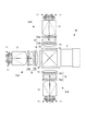
図1は投写型映像表示装置4Aの光学系を示した図である。この投写型映像表示装置4Aは3つの照明装置51R,51G,51Bを備える(以下、個々の照明装置を特定しないで示すときには、符号”51”を用いる)。各照明装置51は、4個のLED(発光ダイオード)11…と、コリメータレンズ13と、インテグレータレンズ14と、レンズ15と、を備えて成る。
FIG. 1 is a diagram showing an optical system of the
各LED11は、LEDチップとLED基板とヒートシンク(放熱板)とを備えて成る。また、各LED11は、図2にも示すように、LEDチップから出射された光を集光するためのレンズ(以下、LEDレンズという)11aを備えている。照明装置51RにおけるLED11は赤色光を出射し、照明装置51GにおけるLED11は緑色光を出射し、照明装置51BにおけるLED11は青色光を出射する。
Each
各照明装置51における4個のLED11…はその主光線軸をコリメータレンズ13の光軸(図1及び図2において点線で示している)に対して傾けて配置されている。前記4個のLED11…は、前記光軸の側から見ると、図3に示しているように配置される。そして、各LED11から出射された光は前記LEDレンズ11aにて集光され、前記コリメータレンズ13の光入射面(平面)と前記光軸とが交わる点を中心とした小領域Zに導かれる。
The four
前記コリメータレンズ13は、前記小領域Zから入射された光を平行光化して出射する。なお、LEDレンズ11aにて集光された入射光の角度をθ1 とし、入射後の広がり角度をθ2 とすると(図2参照)、θ1 >θ2 の関係が成り立つ。また、コリメータレンズ13の屈折率nを1.5とすると、θ2 <41.82°の関係が成り立つ。
The
前記コリメータレンズ13の光出射側にはインテグレータレンズ14が設けられている。インテグレータレンズ14は、一対のフライアイレンズ14a,14bにて構成されており、個々のレンズ対が前記コリメータレンズ13から出射された光を液晶表示パネル1の全面へ導くようになっている。すなわち、LEDチップ11から出射された光は液晶表示パネル1へインテグレートされて導かれることになるため、液晶表示パネル1に導かれる光の輝度分布に不均一が生じるのを抑制することができる。
An
図示はしていないが、インテグレータレンズ14と集光レンズ15との間に偏光変換装置を設けておいてもよい。この偏光変換装置は、偏光ビームスプリッタアレイ(以下、PBSアレイと称する)によって構成される。PBSアレイは、偏光分離膜と位相差板(1/2λ板)とを備える。PBSアレイの各偏光分離膜は、フライアイレンズ対13からの光のうち例えばP偏光を通過させ、S偏光を90°光路変更する。光路変更されたS偏光は隣接の偏光分離膜にて反射されて出射される。一方、偏光分離膜を透過したP偏光はその前側(光出射側)に設けてある前記位相差板によってS偏光に変換されて出射される。すなわち、ほぼ全ての光はS偏光に変換される。勿論、ほぼ全ての光をP偏光に変換することもできる。
Although not shown, a polarization conversion device may be provided between the
液晶表示パネル1R,1B,1Gには図示しないドライバから各色用の液晶駆動信号(映像信号)が供給される。各液晶表示パネル1を透過することで変調された各色映像光は、クロスダイクロイックプリズム2によって合成されてフルカラー映像光となる。このフルカラー映像光は、投写レンズ3によって拡大投写され、図示しないスクリーン上に投影表示される。
A liquid crystal drive signal (video signal) for each color is supplied from a driver (not shown) to the liquid
前記照明装置51においては、LED11はその主光線軸をコリメータレンズ13の光軸に対して傾けて配置されており、LED11から出射された光はコリメータレンズ13の光入射面と光軸とが交わる点を中心とした小領域Zに集光される。従って、LED11を複数設けたとしても、これら複数のLED11は前記小領域Z上に存在する1点の光源(単一光源)と見做すことができ、次段の光学部材(上記の例ではコリメータレンズ13)の設計が容易になり、高効率で光を伝達することが可能になる。なお、コリメータレンズ13上の前記小領域Zは平面に限るものではない。
In the
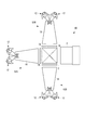
図4は投写型映像表示装置4Bを示した説明図である。投写型映像表示装置4Aとの相違点は、4個のLED(発光ダイオード)12…とロッドインテグレータ16とから成る照明装置52(52R,52G,52B)を備えている点である。照明装置52RにおけるLED12は赤色光を出射し、照明装置52GにおけるLED12は緑色光を出射し、照明装置52BにおけるLED12は青色光を出射する。
FIG. 4 is an explanatory view showing the
各照明装置52の各LED12は、図5にも示しているように、半球レンズカバーを有するLEDチップの光出射側に角度制御レンズ12aを備える。前記角度制御レンズ12aは、回転対称な形状を有する透明部材から成り、中央部の凸状曲面領域(光出射領域)と、周辺側曲面領域(光出射領域)と、周辺側曲面反射領域と、中央の凹状曲面領域(光入射領域)とから成る。LEDチップから出射された光のうち、前記周辺側曲面反射領域にて反射された光は、周辺側曲面領域から前方向(光の出射角度制御において予定している方向)に出射される。また、前記LEDチップから出射された光のうち、中央部の凸状曲面領域に進む光も、前方向(光の出射角度制御において予定している方向)に出射される。なお、角度制御レンズ12aは上記のような形状に限るものではなく、他の形状を採用してもよいし、或いは、単なる両凸レンズ或いは片凸レンズ等でもよい。
As shown in FIG. 5, each LED 12 of each
各照明装置52における4個のLED12…はその主光線軸をロッドインテグレータ16の光軸に対して傾けて配置されている。そして、各LED12から出射された光は、前記角度制御レンズ12aにて分散角が制御され、前記ロッドインテグレータ16の光入射面に導かれる。
The four
ロッドインテグレータ16に入射した光は、ロッド内面で反射を繰り返し、インテグレートされて出射される。ロッドインテグレータ16は、その光出射面が光入射面よりも大きいテーパ型となっており、出射光の低分散角化が期待できるものとなっている。勿論、このようなテーパ型に限るものではなく、直方体形状のロッドインテグレータを採用できる。また、ロッドインテグレータ16は内面が反射面とされた中空構造を有するものでもよいし、透明ガラス等から成る非中空構造を有するものでもよい。また、ロッドインテグレータ16の光入射面は平面に限らず、曲面形状或いは凹凸形状を有することによって光の取り込み効率を向上させたものでもよい。
The light incident on the
偏光変換装置をロッドインテグレータ16の光出射側に設けてもよい。この場合の偏光変換装置はロッドインテグレータ16の光出射部の大きさに対応した単一のPBS(偏光ビームスプリッタ)と、このPBSにおける偏光分離膜に平行に設けられたミラーと、前記ミラー又はPBSの光出射側に設けた位相差板とを備えればよい。ただし、この場合には、偏光変換装置の光出射部の大きさはロッドインテグレータ16の光出射部の大きさの2倍になる。従って、偏光変換装置の光出射部の全体形状が液晶パネルの縦横比に略一致させるのが望ましい。
A polarization conversion device may be provided on the light exit side of the
なお、以上説明した例では、投写型映像表示装置4A,4Bの各照明装置は4個のLEDを有したが、5個以上のLEDを有するもの、或いは、一つのLEDを有するものでもよい。また、複数のLEDの全てが光軸に対して斜めに配置されることに限るものではなく、LEDの主光線軸が次段の光学部材の光軸と平行に配置されるLEDが存在していてもよいものである。
In the example described above, each of the illumination devices of the
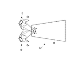
図6は投写型映像表示装置4Cを示した説明図である。この投写型映像表示装置4Cは、ロッドインテグレータ16と、赤色光を出射するLED12Rと、緑色光を出射するLED12Gと、青色光を出射するLED12Bと、を備える。これら3個のLED12R,12G,12Bはその主光線軸をロッドインテグレータ16の光軸に対して傾けて配置されている。LEDの個数は上記3個に限るものではなく、ホワイトバランスの観点から個数を調整すればよい。ロッドインテグレータ16の光出射側には液晶表示パネル1Xが設けられる。
FIG. 6 is an explanatory view showing the
液晶表示パネル1Xは、RGBカラーフィルタを備えた構造、或いはRGBカラーフィルタを備えない構造を有する。RGBカラーフィルタを備える構造の液晶表示パネル1Xを用いる場合には、全LED12R,12G,12Bを同時点灯して白色光を液晶表示パネル1Xに導く。前記RGBカラーフィルタを備えない構造の液晶表示パネルを用いる場合には、各LED12R,12G,12Bを時分割で点灯させると共に、この点灯のタイミングに同期させて液晶表示パネル1Xに各色の映像信号を供給する。
The liquid
図7は三板式の投写型映像表示装置4Dを示した説明図である。この投写型映像表示装置4Dは、一例として照明装置51Wを備える。照明装置51Wは照明装置51においてLEDとして白色光を出射するLED11Wを備えたものである。照明装置51Wから出射された白色光は第1ダイクロイックミラー68へと導かれる。第1ダイクロイックミラー68は、赤色波長帯域の光を透過し、シアン(緑+青)の波長帯域の光を反射する。第1ダイクロイックミラー68を透過した赤色波長帯域の光は、反射ミラー69にて反射されて光路を変更される。反射ミラー69にて反射された赤色光はコンデンサレンズ70を経て赤色光用の透過型の液晶表示パネル81を透過することによって光変調される。一方、第1ダイクロイックミラー68にて反射したシアンの波長帯域の光は、第2ダイクロイックミラー71に導かれる。
FIG. 7 is an explanatory view showing a three-plate
第2ダイクロイックミラー71は、青色波長帯域の光を透過し、緑色波長帯域の光を反射する。第2ダイクロイックミラー71にて反射した緑色波長帯域の光はコンデンサレンズ72を経て緑色光用の透過型の液晶表示パネル82に導かれ、これを透過することによって光変調される。また、第2ダイクロイックミラー71を透過した青色波長帯域の光は、反射ミラー74,76、リレーレンズ73,75、及びコンデンサレンズ77を経て青色光用の透過型の液晶表示パネル83に導かれ、これを透過することによって光変調される。
The second
各液晶表示パネル81,82,83は、入射側偏光板81a,82a,83aと、一対のガラス基板(画素電極や配向膜を形成してある)間に液晶を封入して成るパネル部81b,82b,83bと、出射側偏光板81c,82c,83cとを備えて成る。液晶表示パネル81,82,83を経ることで変調された変調光(各色映像光)は、クロスダイクロイックプリズム78によって合成されてカラー映像光となる。このカラー映像光は、投写レンズ79によって拡大投写され、スクリーン上に投影表示される。
Each of the liquid
また、例えば、図4に示した各色光を出射する照明装置(52R,52G,52B)を用い、これら照明装置からの色光(赤色光と青色光と緑色光)をクロスダイクロイックプリズム或いはクロスダイクロイックミラーによって同一方向に導く構成の照明装置を採用できる(前記クロスダイクロイックプリズム等の光出射側にロッドインテグレータを設けてもよい)。勿論、各色用の照明装置としてはこの発明の他の照明装置を用いることもできる(例えば、照明装置51R,51G,51Bを用いる場合は、インテグレータレンズ14を設けない構成も採用できる)。各色光を同一方向に導く照明装置を用いる投写型映像表示装置で用いられる液晶表示パネルは、RGBカラーフィルタを備えた構造、或いはRGBカラーフィルタを備えない構造を有する。RGBカラーフィルタを備える構造の液晶表示パネルを用いる場合には、全照明装置を同時点灯して白色光を液晶表示パネルに導く。前記RGBカラーフィルタを備えない構造の液晶表示パネルを用いる場合には、各照明装置を時分割で順次に所定時間点灯させると共に、この所定時間点灯のタイミングに同期させて液晶表示パネルに各色の映像信号を供給する。
Further, for example, the illumination devices (52R, 52G, and 52B) that emit each color light shown in FIG. 4 are used, and the color light (red light, blue light, and green light) from these illumination devices is used as a cross dichroic prism or a cross dichroic mirror. It is possible to employ an illumination device configured to guide in the same direction (a rod integrator may be provided on the light emission side of the cross dichroic prism or the like). Of course, other illumination devices of the present invention can be used as the illumination device for each color (for example, when the
以上の説明において、投写型映像表示装置は透過型の液晶パネルを用いることとしたが、これに限らず、反射型の液晶パネルを用いてもよいし、これら液晶パネルに替えて、画素となる多数の微小ミラーを個々に駆動するタイプの表示パネルを用いることとしてもよい。また、以上説明した照明装置において、投写レンズに代えて投写用の曲面ミラーを備えてもよい。また、固体発光素子はLEDに限らず、有機或いは無機のEL(エレクトロルミネッセンス)などを用いてもよい。 In the above description, the projection-type image display device uses a transmissive liquid crystal panel. However, the present invention is not limited to this, and a reflective liquid crystal panel may be used, or a pixel instead of the liquid crystal panel may be used. A display panel of a type in which a large number of micromirrors are individually driven may be used. In the illumination device described above, a curved curved mirror for projection may be provided instead of the projection lens. Further, the solid light emitting element is not limited to an LED, and an organic or inorganic EL (electroluminescence) may be used.
2 クロスダイクロイックプリズム
4A,4B,4C,4D 投写型映像表示装置
11 LED
11a レンズ
12 LED
12a 角度制御レンズ
13 コリメータレンズ
14 インテグレータレンズ
16 ロッドインテグレータ
51 照明装置
52 照明装置
2 Cross
12a
Claims (20)
Priority Applications (1)
| Application Number | Priority Date | Filing Date | Title |
|---|---|---|---|
| JP2005087221A JP2006267714A (en) | 2005-03-24 | 2005-03-24 | Illuminating device and projection type video display device |
Applications Claiming Priority (1)
| Application Number | Priority Date | Filing Date | Title |
|---|---|---|---|
| JP2005087221A JP2006267714A (en) | 2005-03-24 | 2005-03-24 | Illuminating device and projection type video display device |
Publications (2)
| Publication Number | Publication Date |
|---|---|
| JP2006267714A true JP2006267714A (en) | 2006-10-05 |
| JP2006267714A5 JP2006267714A5 (en) | 2007-06-14 |
Family
ID=37203750
Family Applications (1)
| Application Number | Title | Priority Date | Filing Date |
|---|---|---|---|
| JP2005087221A Pending JP2006267714A (en) | 2005-03-24 | 2005-03-24 | Illuminating device and projection type video display device |
Country Status (1)
| Country | Link |
|---|---|
| JP (1) | JP2006267714A (en) |
Cited By (2)
| Publication number | Priority date | Publication date | Assignee | Title |
|---|---|---|---|---|
| WO2007135975A1 (en) | 2006-05-19 | 2007-11-29 | Mitsubishi Chemical Corporation | Nitrogen-containing alloy and method for producing phosphor by using the same |
| WO2010111493A2 (en) * | 2009-03-26 | 2010-09-30 | Scale Timothy J | Led replacement projector light source |
Citations (4)
| Publication number | Priority date | Publication date | Assignee | Title |
|---|---|---|---|---|
| JP2000112031A (en) * | 1998-06-04 | 2000-04-21 | Seiko Epson Corp | Light source device, optical device and liquid crystal display device |
| JP2000231344A (en) * | 1999-02-10 | 2000-08-22 | Toshiba Corp | Illuminator for projection type display device |
| JP2004220015A (en) * | 2002-12-26 | 2004-08-05 | Sanyo Electric Co Ltd | Lighting unit and projection video display device |
| JP2004341424A (en) * | 2003-05-19 | 2004-12-02 | Seiko Epson Corp | Light transmission body, illuminator, and projection type display device |
-
2005
- 2005-03-24 JP JP2005087221A patent/JP2006267714A/en active Pending
Patent Citations (4)
| Publication number | Priority date | Publication date | Assignee | Title |
|---|---|---|---|---|
| JP2000112031A (en) * | 1998-06-04 | 2000-04-21 | Seiko Epson Corp | Light source device, optical device and liquid crystal display device |
| JP2000231344A (en) * | 1999-02-10 | 2000-08-22 | Toshiba Corp | Illuminator for projection type display device |
| JP2004220015A (en) * | 2002-12-26 | 2004-08-05 | Sanyo Electric Co Ltd | Lighting unit and projection video display device |
| JP2004341424A (en) * | 2003-05-19 | 2004-12-02 | Seiko Epson Corp | Light transmission body, illuminator, and projection type display device |
Cited By (3)
| Publication number | Priority date | Publication date | Assignee | Title |
|---|---|---|---|---|
| WO2007135975A1 (en) | 2006-05-19 | 2007-11-29 | Mitsubishi Chemical Corporation | Nitrogen-containing alloy and method for producing phosphor by using the same |
| WO2010111493A2 (en) * | 2009-03-26 | 2010-09-30 | Scale Timothy J | Led replacement projector light source |
| WO2010111493A3 (en) * | 2009-03-26 | 2011-01-13 | Scale Timothy J | Led replacement projector light source |
Similar Documents
| Publication | Publication Date | Title |
|---|---|---|
| US7237909B2 (en) | Optical member, illuminating device, and projection type video display | |
| JP4477571B2 (en) | Illumination unit and image projection apparatus employing the same | |
| JP4550721B2 (en) | Illumination unit and image projection apparatus employing the same | |
| US6769773B1 (en) | Projector with UV light source | |
| JP2006048044A (en) | Illumination unit and image projection apparatus employing the same | |
| JP2006243603A (en) | Condensing element, lighting device, and projection image display device | |
| JP2006018196A (en) | Illuminator and projection video display device | |
| JP4183663B2 (en) | Illumination device and projection display device | |
| WO2020230510A1 (en) | Image projection apparatus | |
| US11300866B2 (en) | Light source apparatus and projector | |
| US20120081679A1 (en) | Light source apparatus and projection display apparatus | |
| JP5153535B2 (en) | Image projection device | |
| JP2006138952A (en) | Illuminator and projection type video display device | |
| JP2007065412A (en) | Illuminating device and projection type video display device | |
| JP2004226613A (en) | Illuminator and projection type video display device | |
| JP2006208894A (en) | Optical member, illumination apparatus and projection type image display apparatus | |
| JP2006039338A (en) | Lighting system and projection type video display device | |
| JP2007003847A (en) | Illuminator and projection type image display device | |
| JP2006267714A (en) | Illuminating device and projection type video display device | |
| JP2010169723A (en) | Projector | |
| WO2019181404A1 (en) | Image display device | |
| JP2007127795A (en) | Projection optical device, multiple-color light illuminating device and projection type image display device | |
| JP2007010972A (en) | Illuminator and projection type image display apparatus | |
| JP2006258899A (en) | Condensing element, illuminating device and projection type image display apparatus | |
| JP2006317925A (en) | Optical member, illumination device, and projection type video display apparatus |
Legal Events
| Date | Code | Title | Description |
|---|---|---|---|
| A521 | Written amendment |
Free format text: JAPANESE INTERMEDIATE CODE: A523 Effective date: 20070423 |
|
| A621 | Written request for application examination |
Free format text: JAPANESE INTERMEDIATE CODE: A621 Effective date: 20070622 |
|
| A977 | Report on retrieval |
Free format text: JAPANESE INTERMEDIATE CODE: A971007 Effective date: 20101028 |
|
| A131 | Notification of reasons for refusal |
Free format text: JAPANESE INTERMEDIATE CODE: A131 Effective date: 20101102 |
|
| A521 | Written amendment |
Free format text: JAPANESE INTERMEDIATE CODE: A523 Effective date: 20101228 |
|
| A02 | Decision of refusal |
Effective date: 20110215 Free format text: JAPANESE INTERMEDIATE CODE: A02 |