JP2006255408A - Radially expandable access system equipped with trocar seal - Google Patents
Radially expandable access system equipped with trocar seal Download PDFInfo
- Publication number
- JP2006255408A JP2006255408A JP2006047567A JP2006047567A JP2006255408A JP 2006255408 A JP2006255408 A JP 2006255408A JP 2006047567 A JP2006047567 A JP 2006047567A JP 2006047567 A JP2006047567 A JP 2006047567A JP 2006255408 A JP2006255408 A JP 2006255408A
- Authority
- JP
- Japan
- Prior art keywords
- sleeve body
- sleeve
- radially expandable
- access system
- distal end
- Prior art date
- Legal status (The legal status is an assumption and is not a legal conclusion. Google has not performed a legal analysis and makes no representation as to the accuracy of the status listed.)
- Pending
Links
Images


Classifications
-
- A—HUMAN NECESSITIES
- A61—MEDICAL OR VETERINARY SCIENCE; HYGIENE
- A61B—DIAGNOSIS; SURGERY; IDENTIFICATION
- A61B17/00—Surgical instruments, devices or methods, e.g. tourniquets
- A61B17/34—Trocars; Puncturing needles
- A61B17/3417—Details of tips or shafts, e.g. grooves, expandable, bendable; Multiple coaxial sliding cannulas, e.g. for dilating
- A61B17/3421—Cannulas
- A61B17/3439—Cannulas with means for changing the inner diameter of the cannula, e.g. expandable
-
- A—HUMAN NECESSITIES
- A61—MEDICAL OR VETERINARY SCIENCE; HYGIENE
- A61B—DIAGNOSIS; SURGERY; IDENTIFICATION
- A61B17/00—Surgical instruments, devices or methods, e.g. tourniquets
- A61B17/00234—Surgical instruments, devices or methods, e.g. tourniquets for minimally invasive surgery
-
- A—HUMAN NECESSITIES
- A61—MEDICAL OR VETERINARY SCIENCE; HYGIENE
- A61B—DIAGNOSIS; SURGERY; IDENTIFICATION
- A61B17/00—Surgical instruments, devices or methods, e.g. tourniquets
- A61B17/34—Trocars; Puncturing needles
- A61B17/3417—Details of tips or shafts, e.g. grooves, expandable, bendable; Multiple coaxial sliding cannulas, e.g. for dilating
- A61B17/3421—Cannulas
- A61B17/3431—Cannulas being collapsible, e.g. made of thin flexible material
-
- A—HUMAN NECESSITIES
- A61—MEDICAL OR VETERINARY SCIENCE; HYGIENE
- A61B—DIAGNOSIS; SURGERY; IDENTIFICATION
- A61B17/00—Surgical instruments, devices or methods, e.g. tourniquets
- A61B17/34—Trocars; Puncturing needles
- A61B17/3474—Insufflating needles, e.g. Veress needles
-
- A—HUMAN NECESSITIES
- A61—MEDICAL OR VETERINARY SCIENCE; HYGIENE
- A61B—DIAGNOSIS; SURGERY; IDENTIFICATION
- A61B90/00—Instruments, implements or accessories specially adapted for surgery or diagnosis and not covered by any of the groups A61B1/00 - A61B50/00, e.g. for luxation treatment or for protecting wound edges
- A61B90/40—Apparatus fixed or close to patients specially adapted for providing an aseptic surgical environment
Abstract
Description
本開示は、一般的に、外科手術手順の間に内部の手術部位にアクセスを提供するための装置および方法に関し、より詳細には、狭い直径の構成の間に経皮的にまたはそれ以外で導入され得、導入の後にその中を通るより大きな直径の外科手術用器具の通過に適応するように半径方向に拡張し得るアクセスシステムに関する。 The present disclosure relates generally to an apparatus and method for providing access to an internal surgical site during a surgical procedure, and more particularly percutaneously or otherwise during a narrow diameter configuration. It relates to an access system that can be introduced and can be radially expanded to accommodate passage of larger diameter surgical instruments therethrough after introduction.
最小の侵襲性の外科手術手順は、小さい直径のアクセス管(代表的には、5〜12mm)(通常、トロカールと呼ばれる)を使用して内部外科手術部位への経皮的アクセスを得ることに頼っている。この小さい直径のアクセス管は、皮膚を貫通し、所望の外科手術部位に対して開いている。次いで、ビューイングスコープを、トロカールのようなものを通して導入し、外科医が、ビューイングスコープに接続されたビデオモニター上の手術部位を見ながら、他の適切に配置されたトロカールを通して導入された器具を使用して手術を行う。このように、外科医は、外科手術部位においていくつかの5mm〜12mmの穿刺のみを必要とする幅広い種々の外科手術手順を実行し得る。結果として、患者の外傷および回復時間は、代表的に減少する。 The minimally invasive surgical procedure involves using a small diameter access tube (typically 5-12 mm) (usually called a trocar) to gain percutaneous access to the internal surgical site. Rely on. This small diameter access tube penetrates the skin and is open to the desired surgical site. The viewing scope is then introduced through something like a trocar, and the surgeon sees the surgical site on a video monitor connected to the viewing scope and introduces the instrument introduced through another appropriately placed trocar. Use to perform surgery. In this manner, the surgeon may perform a wide variety of surgical procedures that require only a few 5-12 mm punctures at the surgical site. As a result, patient trauma and recovery time are typically reduced.
特に最小の侵襲性の外科手術手順は、しばしば、手術部位である身体の領域を見るために使用される観察器械の型に基づいて呼ばれる。例えば、腹部領域の手順(見るための腹腔鏡に頼る)は、代表的に、腹腔鏡手順と呼ばれる。このような腹腔鏡手順において、患者の腹部領域は、代表的に、腹壁を持ち上げ、所望の手順を行うために十分な手術空間を作り出すために、ガス注入される(加圧気体で満たされる)。従って、腹腔鏡手順において使用されるトロカールは、ガス注入気体(insufflating gas)の漏れを防ぎながら、観察器械または外科手術機器の通過を可能にするために、近位端に弁を備える。ガス注入を使用するよりも腹部を機械的に拡張することによって、腹腔鏡手順を行うこともまた提案されている。 Particularly minimally invasive surgical procedures are often referred to based on the type of viewing instrument used to view the region of the body that is the surgical site. For example, an abdominal region procedure (which relies on a laparoscope for viewing) is typically referred to as a laparoscopic procedure. In such a laparoscopic procedure, the patient's abdominal region is typically insufflated (filled with pressurized gas) to lift the abdominal wall and create sufficient surgical space to perform the desired procedure. . Accordingly, trocars used in laparoscopic procedures include a valve at the proximal end to allow passage of observation or surgical instruments while preventing leakage of insufflating gas. It has also been proposed to perform a laparoscopic procedure by mechanically expanding the abdomen rather than using gas injection.
最近、半径方向に拡張可能なアクセスシステムが、開発され、特許文献1;特許文献2;特許文献3;特許文献4;特許文献5;特許文献6;特許文献7;特許文献8;特許文献9、ならびに米国特許出願番号2001/0039430;同2002/0002360;同2003/0023259;および同2003/0199809(これらのそれぞれの内容は、本明細書中において参考として援用される)に示され、記載されている。これらに開示される半径方向に拡張可能なアクセスシステムは、気腹針、この気腹針上に配置されている間に経皮的に導入される拡張可能なスリーブ構成要素、近位端に永久的に固定された気体停止(pneumostasis)弁を有するカニューレ、およびカニューレ内に取り外し可能に挿入されてスリーブの拡張部材を形成する閉塞具を備える。腹腔鏡手順の場合、針/スリーブアセンブリが経皮的に導入され、腹腔にガス注入した後に、針がスリーブから取り除かれ、カニューレ/閉塞具アセンブリがスリーブを通して導入される。このように、スリーブ(最初に、2〜3mmの範囲の直径を有する)は、カニューレサイズに依存して最終直径に拡張する(5mm、10mm、または12mmから選択され得る)。半径方向に拡張可能なアクセスシステムの使用は、多くの利点(患者に対する外傷の減少、および先に導入されたスリーブを通してより大きな直径のカニューレを有するカニューレを置換する能力)を有する。
半径方向に拡張可能なアクセスシステムが従来のトロカールを超える実質的な進歩を提供しながら、改善された半径方向に拡張可能なアクセスシステム、このようなシステムのための構成要素キット、およびこのようなシステムを再構成し、再使用するための方法についての必要性および要求が存在する。 Improved radially expandable access system, component kit for such a system, and such, while the radially expandable access system provides a substantial advance over conventional trocars There is a need and need for a method for reconfiguring and reusing a system.
(要旨)
本開示は、狭い直径の構成の間に経皮的にまたはそれ以外で導入され得、そして導入後、より大きな直径の外科手術機器の通過に適応するように半径方向に拡張され得るアクセスシステムに関する。
(Summary)
The present disclosure relates to an access system that can be introduced percutaneously or otherwise during a narrow diameter configuration and that can be radially expanded to accommodate passage of larger diameter surgical instruments after introduction. .
本開示の局面に従って、アクセスシステムとともに使用される、半径方向に拡張可能なスリーブ構成要素が提供される。スリーブ構成要素は、ハンドルであって、それを通る通路を有するハンドル;およびスリーブ本体であって、ハンドルに接続される近位端、遠位端、ハンドルの通路と整列した軸管腔を有し、このスリーブ本体が一定の長さを有する、スリーブ本体を備える。スリーブ本体は、半径方向に拡張可能な編組物(braid)から構築され、この編組物は、スリーブ本体が半径方向に拡張する場合に、スリーブ本体の長さを軸方向に短くする非弾性フィラメントのメッシュから形成される。スリーブ本体の遠位端は、半径方向外向きにフレア状(flare)になっている。 In accordance with aspects of the present disclosure, a radially expandable sleeve component for use with an access system is provided. The sleeve component is a handle having a passage therethrough; and a sleeve body having a proximal end connected to the handle, a distal end, and an axial lumen aligned with the passage of the handle The sleeve body includes a sleeve body having a certain length. The sleeve body is constructed from a radially expandable braid that is made of an inelastic filament that shortens the length of the sleeve body in the axial direction when the sleeve body expands radially. Formed from a mesh. The distal end of the sleeve body is flared radially outward.
半径方向に拡張可能なスリーブは、スリーブ本体を実質的に包む(encase)シースをさらに備え得る。望ましくは、スリーブ本体の長さは、拡張アセンブリが半径方向に拡張可能なスリーブ構成要素と作動可能に関連する場合に、拡張アセンブリのカニューレ管の長さよりも長い。 The radially expandable sleeve may further comprise a sheath that substantially encases the sleeve body. Desirably, the length of the sleeve body is greater than the length of the cannula tube of the expansion assembly when the expansion assembly is operatively associated with the radially expandable sleeve component.
スリーブ本体のフレア状の遠位端が半径方向に拡張可能なスリーブ構成要素からの機器の引き抜きを可能にすることが企図される。 It is contemplated that the flared distal end of the sleeve body allows for the withdrawal of the device from the radially expandable sleeve component.
本開示の別の局面に従って、アクセスシステムが提供される。アクセスシステムは、半径方向に拡張可能なスリーブ構成要素を備え、このスリーブ構成要素は、ハンドルであって、それを通る通路を有するハンドル;およびスリーブ本体であって、ハンドルに接続される近位端、遠位端、ハンドルの通路と整列した軸管腔を有し、このスリーブ本体が一定の長さを有する、スリーブ本体を備える。スリーブ本体の遠位端は、半径方向外向きにフレア状になっている。アクセスシステムは、さらに、カニューレ管を備え、このカニューレ管は、近位端、遠位端、およびこのカニューレ管を通って延びる管腔を備える。カニューレ管は、半径方向に拡張可能なスリーブ構成要素のハンドルの開口部中に受け入れられる大きさである。カニューレ管は、カニューレ管が半径方向に拡張可能なスリーブ構成要素のスリーブ本体中に完全に挿入された場合、スリーブ本体の長さよりも短い長さを有する。 In accordance with another aspect of the present disclosure, an access system is provided. The access system comprises a radially expandable sleeve component, the sleeve component being a handle having a passage therethrough; and a sleeve body, the proximal end connected to the handle A sleeve body having a distal end, an axial lumen aligned with the passage of the handle, the sleeve body having a length. The distal end of the sleeve body is flared radially outward. The access system further includes a cannula tube that includes a proximal end, a distal end, and a lumen extending through the cannula tube. The cannula tube is sized to be received in the opening of the handle of the radially expandable sleeve component. The cannula tube has a length that is less than the length of the sleeve body when the cannula tube is fully inserted into the sleeve body of the radially expandable sleeve component.
望ましくは、カニューレ管が半径方向に拡張可能なスリーブ構成要素のスリーブ本体内に完全に挿入された場合、スリーブ本体のフレア状の遠位端は、カニューレ管の遠位端を超えて延びる。半径方向に拡張可能なスリーブは、さらに、その長さの少なくとも一部に沿ってスリーブ本体を包むシースを備える。 Desirably, when the cannula tube is fully inserted within the sleeve body of the radially expandable sleeve component, the flared distal end of the sleeve body extends beyond the distal end of the cannula tube. The radially expandable sleeve further comprises a sheath that encloses the sleeve body along at least a portion of its length.
1つの実施形態において、スリーブ本体は、半径方向に拡張可能な編組物から構築される。この編組物は、スリーブ本体が半径方向に拡張する場合、スリーブ本体の長さを実質的に短くする非弾性フィラメントのメッシュから形成される。 In one embodiment, the sleeve body is constructed from a radially expandable braid. The braid is formed from a mesh of inelastic filaments that substantially shortens the length of the sleeve body when the sleeve body expands radially.
望ましくは、シースは、半径方向に拡張していない状態で、スリーブ本体のフレア状の遠位端を維持する。スリーブ本体のフレア状の遠位端が、シースを取り除く際に、形をとることが企図される。 Desirably, the sheath maintains the flared distal end of the sleeve body in a non-radially expanded state. It is contemplated that the flared distal end of the sleeve body will take shape upon removal of the sheath.
本開示のなお別の局面に従って、アクセスシステムが提供される。このアクセスシステムは、半径方向に拡張可能なスリーブ構成要素を備え、このスリーブ構成要素は、ハンドルであって、それを通る通路を有するハンドル;およびスリーブ本体であって、ハンドルに接続される近位端、遠位端、ハンドルの通路と整列した軸管腔を有し、このスリーブ本体が一定の長さを有する、スリーブ本体を備える。スリーブ本体の遠位端は、半径方向内側にテーパー状である。このアクセスシステムは、さらに、カニューレ管を備え、このカニューレ管は、近位端、遠位端、およびこのカニューレ管を通って延びる管腔を備える。カニューレ管は、半径方向に拡張可能なスリーブ構成要素のハンドルの開口部中に受け入れられる大きさである。カニューレ管は、カニューレ管が半径方向に拡張可能なスリーブ構成要素のスリーブ本体中に完全に挿入された場合、スリーブ本体の長さよりも短い長さを有し、その結果、スリーブ本体のテーパー状の遠位端が、半径方向に拡張可能なスリーブ構成要素中に挿入される機器と係合する。 In accordance with yet another aspect of the present disclosure, an access system is provided. The access system comprises a radially expandable sleeve component, the sleeve component being a handle having a passage therethrough; and a sleeve body, proximal to the handle The sleeve body includes a sleeve body having an end, a distal end, an axial lumen aligned with the handle passageway, the sleeve body having a length. The distal end of the sleeve body is tapered radially inward. The access system further includes a cannula tube that includes a proximal end, a distal end, and a lumen extending through the cannula tube. The cannula tube is sized to be received in the opening of the handle of the radially expandable sleeve component. The cannula tube has a length that is less than the length of the sleeve body when the cannula tube is fully inserted into the sleeve body of the radially expandable sleeve component, resulting in a tapered shape of the sleeve body. The distal end engages a device that is inserted into the radially expandable sleeve component.
アクセスシステムは、カニューレ管の管腔内で取り外し可能に受け入れ可能な閉塞具をさらに備え得る。閉塞具は、閉塞具がカニューレ管の管腔内に配置される場合に、カニューレ管の遠位端から遠位に延びるテーパー状の遠位端を有する。このアクセスシステムは、さらに、気腹針を備え、この気腹針は、管状針;および管状針内に取り外し可能に受け入れ可能な内部スタイレットを備え得る。 The access system may further comprise an obturator removably receivable within the lumen of the cannula tube. The obturator has a tapered distal end that extends distally from the distal end of the cannula tube when the obturator is disposed within the lumen of the cannula tube. The access system further comprises a pneumoperitoneum, which can comprise a tubular needle; and an internal stylet removably receivable within the tubular needle.
望ましくは、カニューレ管が半径方向に拡張可能なスリーブ構成要素のスリーブ本体内に完全に挿入された場合、スリーブ本体のフレア状の遠位端は、カニューレ管の遠位端を超えて延びる。 Desirably, when the cannula tube is fully inserted within the sleeve body of the radially expandable sleeve component, the flared distal end of the sleeve body extends beyond the distal end of the cannula tube.
半径方向に拡張可能なスリーブは、さらに、シースであって、その長さの少なくとも一部に沿ってスリーブ本体を包むシースを備える。シースは、望ましくは、半径方向にテーパー状の状態で、スリーブ本体の半径方向内側にテーパー状の遠位端を維持する。使用において、スリーブ本体の半径方向内側にテーパー状の遠位端は、そこからのシースの取り外しの際に半径方向に拡張する。 The radially expandable sleeve further comprises a sheath that wraps the sleeve body along at least a portion of its length. The sheath desirably maintains a tapered distal end radially inward of the sleeve body in a radially tapered manner. In use, the radially inwardly tapered distal end of the sleeve body expands radially upon removal of the sheath therefrom.
上記目的を達成するために、本発明は、例えば、さらに以下を提供する。
(項目1) アクセスシステムとともに使用するための、半径方向に拡張可能なスリーブ構成要素であって、該スリーブ構成要素が、以下:
ハンドルであって、該ハンドルを通る通路を有する、ハンドル;および
スリーブ本体であって、該ハンドルに接続される近位端、遠位端、該ハンドルの通路と整列した軸管腔を有し、該スリーブ本体が一定の長さを有し、該スリーブ本体が、半径方向に拡張可能な編組物から構築され、ここで、該編組物が、該スリーブ本体が半径方向に拡張する場合に該スリーブ本体の長さを軸方向に短くする非弾性フィラメントのメッシュから形成され、該スリーブ本体の遠位端は、半径方向外向きにフレア状になっている、スリーブ本体、
を備える、半径方向に拡張可能なスリーブ構成要素。
(項目2) 項目1に記載の半径方向に拡張可能なスリーブ構成要素であって、前記スリーブ本体を実質的に包むシースをさらに備える、半径方向に拡張可能なスリーブ構成要素。
(項目3) 項目1に記載の半径方向に拡張可能なスリーブ構成要素であって、前記スリーブ本体の長さが、前記拡張アセンブリが該半径方向に拡張可能なスリーブ構成要素と作動可能に関連する場合に拡張アセンブリのカニューレ管の長さより長い、半径方向に拡張可能なスリーブ構成要素。
(項目4) 項目1に記載の半径方向に拡張可能なスリーブ構成要素であって、前記スリーブ本体のフレア状遠位端が、該半径方向に拡張可能なスリーブ構成要素からの機器の引き抜きを容易にする、半径方向に拡張可能なスリーブ構成要素。
(項目5) アクセスシステムであって、以下:
半径方向に拡張可能なスリーブ構成要素であって、以下:
ハンドルであって、該ハンドルを通る通路を有する、ハンドル;および
スリーブ本体であって、該ハンドルに接続される近位端、遠位端、該ハンドルの通路と整列した軸管腔を有し、該スリーブ本体が一定の長さを有し、該スリーブ本体の遠位端は、半径方向外向きにフレア状になっている、スリーブ本体、
を備える、半径方向に拡張可能なスリーブ構成要素;ならびに
カニューレ管であって、該カニューレ管が、近位端、遠位端、および該カニューレ管を通って延びる管腔を備え、該カニューレ管が、半径方向に拡張可能なスリーブ構成要素のハンドルの開口部中に受け入れられる大きさであり、該カニューレ管が、該カニューレ管が該半径方向に拡張可能なスリーブ構成要素のスリーブ本体中に完全に挿入された場合、該スリーブ本体の長さよりも短い長さを有する、カニューレ管、
を備える、アクセスシステム。
(項目6) 項目5に記載のアクセスシステムであって、前記カニューレ管が前記半径方向に拡張可能なスリーブ構成要素のスリーブ本体中に完全に挿入された場合に、該スリーブ本体のフレア状の遠位端が、カニューレ管の遠位端を超えて延びる、アクセスシステム。
(項目7) 項目6に記載のアクセスシステムであって、前記半径方向に拡張可能なスリーブが、さらに、その長さの少なくとも一部に沿って前記スリーブ本体を包むシースを備える、アクセスシステム。
(項目8) 項目7に記載のアクセスシステムであって、前記スリーブ本体が、半径方向に拡張可能な編組物から構築され、ここで、該編組物が、スリーブ本体が半径方向に拡張する場合、該スリーブ本体の長さを実質的に短くする非弾性フィラメントのメッシュから形成される、アクセスシステム。
(項目9) 項目8に記載のアクセスシステムであって、前記シースが、半径方向に拡張していない状態で、スリーブ本体のフレア状の遠位端を維持する、アクセスシステム。
(項目10) 項目9に記載のアクセスシステムであって、前記スリーブ本体のフレア状の遠位端が、それらからシースを取り除く際に、形をとる、アクセスシステム。
(項目11) アクセスシステムであって、以下:
半径方向に拡張可能なスリーブ構成要素であって、以下:
ハンドルであって、それを通る通路を有するハンドル;および
スリーブ本体であって、該スリーブ本体が、該ハンドルに接続される近位端、遠位端、該ハンドルの通路と整列した軸管腔を有し、該スリーブ本体が一定の長さを有し、ここで、該スリーブ本体の遠位端が、半径方向内側にテーパー状である、スリーブ本体、
を備える、半径方向に拡張可能なスリーブ構成要素;ならびに
カニューレ管であって、該カニューレ管が、近位端、遠位端、および該カニューレ管を通って延びる管腔を備え、該カニューレ管が、半径方向に拡張可能なスリーブ構成要素のハンドルの開口部中に受け入れられる大きさであり、該カニューレ管が、該カニューレ管が該半径方向に拡張可能なスリーブ構成要素のスリーブ本体中に完全に挿入された場合、該スリーブ本体の長さよりも短い長さを有し、その結果、該スリーブ本体のテーパー状の遠位端が、半径方向に拡張可能なスリーブ構成要素中に挿入される機器と係合する、カニューレ管、
を備える、アクセスシステム。
(項目12) 項目11に記載のアクセスシステムであって、前記カニューレ管の管腔内で取り外し可能に受け入れ可能な閉塞具をさらに備え、該閉塞具は、該閉塞具が該カニューレ管の管腔内に配置される場合に、該カニューレ管の遠位端から遠位に延びるテーパー状の遠位端を有する、アクセスシステム。
(項目13) 項目11に記載のアクセスシステムであって、該アクセスシステムは、さらに、気腹針を備え、該気腹針が、以下:
管状針;および
該管状針内に取り外し可能に受け入れ可能な内部スタイレット
を備える、アクセスシステム。
(項目14) 項目11に記載のアクセスシステムであって、前記カニューレ管が、半径方向に拡張可能なスリーブ構成要素のスリーブ本体内に完全に挿入された場合、スリーブ本体のフレア状の遠位端が、該カニューレ管の遠位端を超えて延びる、アクセスシステム。
(項目15) 項目14に記載のアクセスシステムであって、前記半径方向に拡張可能なスリーブが、さらに、シースであって、その長さの少なくとも一部に沿ってスリーブ本体を包むシースを備える、アクセスシステム。
(項目16) 項目15に記載のアクセスシステムであって、前記シースが、半径方向にテーパー状の状態で、スリーブ本体の半径方向内側にテーパー状の遠位端を維持する、アクセスシステム。
(項目17) 項目16に記載のアクセスシステムであって、前記スリーブ本体の半径方向内側にテーパー状の遠位端が、そこからのシースの取り外しの際に半径方向に拡張する、アクセスシステム。
In order to achieve the above object, the present invention further provides, for example, the following.
(Item 1) A radially expandable sleeve component for use with an access system, the sleeve component comprising:
A handle having a passage through the handle; and a sleeve body having a proximal end connected to the handle, a distal end, an axial lumen aligned with the passage of the handle; The sleeve body has a length, and the sleeve body is constructed from a radially expandable braid, wherein the braid is the sleeve when the sleeve body expands radially. A sleeve body formed from a mesh of inelastic filaments that axially shortens the length of the body, the distal end of the sleeve body flaring radially outwardly;
A radially expandable sleeve component comprising:
2. The radially expandable sleeve component of
3. The radially expandable sleeve component of
4. The radially expandable sleeve component of
(Item 5) Access system, the following:
A radially expandable sleeve component comprising:
A handle having a passage through the handle; and a sleeve body having a proximal end connected to the handle, a distal end, an axial lumen aligned with the passage of the handle; The sleeve body has a length, and the distal end of the sleeve body is flared radially outwardly;
A radially expandable sleeve component; and a cannula tube, the cannula tube comprising a proximal end, a distal end, and a lumen extending through the cannula tube, the cannula tube , Sized to be received in the opening of the handle of the radially expandable sleeve component, wherein the cannula tube is fully within the sleeve body of the radially expandable sleeve component. A cannula tube having a length shorter than the length of the sleeve body when inserted,
An access system comprising:
6. The access system of claim 5, wherein when the cannula tube is fully inserted into the sleeve body of the radially expandable sleeve component, the flared distal end of the sleeve body. An access system, wherein the proximal end extends beyond the distal end of the cannula tube.
7. The access system of claim 6, wherein the radially expandable sleeve further comprises a sheath that encloses the sleeve body along at least a portion of its length.
(Item 8) The access system according to item 7, wherein the sleeve body is constructed from a radially expandable braid, where the braid expands the sleeve body radially, An access system formed from a mesh of inelastic filaments that substantially reduces the length of the sleeve body.
9. The access system according to claim 8, wherein the sheath maintains a flared distal end of the sleeve body in a non-radially expanded state.
10. The access system of claim 9, wherein the flared distal end of the sleeve body takes shape when the sheath is removed from them.
(Item 11) An access system, which is as follows:
A radially expandable sleeve component comprising:
A handle having a passage therethrough; and a sleeve body, the sleeve body having a proximal end connected to the handle, a distal end, and an axial lumen aligned with the passage of the handle. A sleeve body, wherein the sleeve body has a length, wherein a distal end of the sleeve body is tapered radially inward;
A radially expandable sleeve component; and a cannula tube, the cannula tube comprising a proximal end, a distal end, and a lumen extending through the cannula tube, the cannula tube , Sized to be received in the opening of the handle of the radially expandable sleeve component, wherein the cannula tube is fully within the sleeve body of the radially expandable sleeve component. An instrument that, when inserted, has a length that is less than the length of the sleeve body so that the tapered distal end of the sleeve body is inserted into a radially expandable sleeve component; Engage, cannula tube,
An access system comprising:
12. The access system of claim 11, further comprising an obturator removably receivable within the lumen of the cannula tube, the obturator comprising a lumen of the cannula tube. An access system having a tapered distal end extending distally from the distal end of the cannula tube when disposed within.
(Item 13) The access system according to item 11, further comprising an insufflation needle, wherein the insufflation needle is:
An access system comprising: a tubular needle; and an internal stylet removably receivable within the tubular needle.
14. The access system of claim 11, wherein the cannula tube is fully inserted into the sleeve body of the radially expandable sleeve component and the flared distal end of the sleeve body. Extending beyond the distal end of the cannula tube.
15. The access system of
16. The access system according to
17. The access system according to
本開示の他の目的および特徴は、添付の図面とともに、以下の説明を考慮して明らかになる。 Other objects and features of the present disclosure will become apparent in view of the following description in conjunction with the accompanying drawings.
単なる例示として、本開示の半径方向に拡張可能なアクセスシステムの実施形態は、添付の図面を参照して記載される。 By way of example only, embodiments of the radially expandable access system of the present disclosure will be described with reference to the accompanying drawings.
半径方向に拡張可能なアクセスシステムが従来のトロカールを超える実質的な進歩を提供しながら、改善された半径方向に拡張可能なアクセスシステム、このようなシステムのための構成要素キット、およびこのようなシステムを再構成し、再使用するための方法が提供される。 Improved radially expandable access system, component kit for such a system, and such, while the radially expandable access system provides a substantial advance over conventional trocars A method is provided for reconfiguring and reusing a system.
本開示のアクセスシステムは、多様な目的のために、患者の身体内の種々の標的位置内への経皮的貫入を形成し、拡大するために有用である。このような目的としては、排液、器官内薬物投与、給餌、灌流、吸引などが挙げられ、最も通常には、最初の侵襲性の外科手術手順(例えば、腹腔鏡手順、胸腔鏡手順、関節鏡手順、内視鏡手順など)での使用のための観察器械および外科手術機器の導入である。経皮的手順に加えて、本開示のアクセスシステムは、子宮鏡手順、結腸鏡手順および既存の身体孔を通して確立される他の手順における使用を見出す。 The access system of the present disclosure is useful for creating and extending percutaneous penetration into various target locations within a patient's body for a variety of purposes. Such purposes include drainage, intra-organ drug administration, feeding, perfusion, aspiration, etc. Most commonly, the first invasive surgical procedure (eg, laparoscopic, thoracoscopic, joint, etc.) The introduction of observation and surgical instruments for use in mirror procedures, endoscopic procedures, etc.). In addition to percutaneous procedures, the access system of the present disclosure finds use in hysteroscopic procedures, colonoscopic procedures, and other procedures established through existing body holes.
本開示のアクセスシステムは、経皮的手順において特に価値がある。なぜなら、これらは、非常に小さな開始貫入、通常、約5mm未満、より通常には、約4mm未満、しばしば、約3.5mm未満、好ましくは3mm以下を作り出すからである。貫入は、後に、所望の最終サイズ、通常、約5mm〜15mm、より通常には、約5mm〜12mm、代表的には、約5mm〜10mmの範囲の最終直径に拡大される。拡大された貫入は、患者の身体の外側から所望の内部の位置へのアクセス管腔を規定し、アクセス管腔の直径が、本明細書中において以後に、より詳細に記載されるように、変化され得ることが本開示の特定の利点である。非経皮的手順において、アクセスシステムは、その狭い直径の構成で既存の身体孔を通過し得、後に、患者に対して最小の不快さおよび外傷で拡張し得るので、価値がある。 The access system of the present disclosure is particularly valuable in transcutaneous procedures. This is because they create very small initial penetrations, usually less than about 5 mm, more usually less than about 4 mm, often less than about 3.5 mm, preferably less than 3 mm. The penetration is later expanded to a desired final size, typically about 5 mm to 15 mm, more usually about 5 mm to 12 mm, typically about 5 mm to 10 mm. The enlarged penetration defines an access lumen from the outside of the patient's body to the desired internal location, and the diameter of the access lumen is described in more detail later herein. It is a particular advantage of the present disclosure that it can be varied. In non-percutaneous procedures, the access system is valuable because it can pass through existing body holes in its narrow diameter configuration and later expand with minimal discomfort and trauma to the patient.
本開示のアクセスシステムは、異なるサイズの構成に組み立てられ得る多くの個々の構成要素を備える。組み立てられた構成要素はまた、使用後分解され得、これらの構成要素は、異なる患者でのさらなる使用のためにアクセスシステムを再び組み立てる前に、選択的に滅菌または置換され得る。異なる構成要素および構成要素アセンブリならびにサブアセンブリは、以下にさらに詳細に記載される。 The access system of the present disclosure comprises a number of individual components that can be assembled into different sized configurations. The assembled components can also be disassembled after use, and these components can be selectively sterilized or replaced before reassembling the access system for further use in different patients. Different components and component assemblies and subassemblies are described in further detail below.
本明細書中に開示されるトロカールシステムの構成要素の滅菌は、任意の適切な従来の滅菌技術(熱、例えば、蒸気およびオートクレーブ;化学処理、例えば、エチレンオキシド暴露;放射線などを含む)によって達成され得る。使用後に、再使用可能な構成要素は、血液および他の汚染物質を除去するために洗浄され、次いで、好ましくは、蒸気への暴露によって滅菌される。使い捨て構成要素は、通常、配布の前にそれらの包装中に放射線滅菌される。従って、使い捨て構成要素は、通常、包装から使用するために準備される。 Sterilization of the components of the trocar system disclosed herein is accomplished by any suitable conventional sterilization technique (including heat, eg, steam and autoclave; chemical treatment, eg, ethylene oxide exposure; radiation, etc.). obtain. After use, the reusable component is washed to remove blood and other contaminants and then preferably sterilized by exposure to steam. Disposable components are typically radiation sterilized in their packaging prior to distribution. Thus, disposable components are typically prepared for use from packaging.
図1、1Aおよび2を最初に参照する。ここで、類似の参照番号は、同様なまたは同一の構造の要素を同定する。アクセスシステムの一部として使用するために、本開示の実施形態に従って、半径方向に拡張可能なスリーブ構成要素またはトロカールシールは、10として一般的に示される。本明細書中で使用される場合、用語「遠位」とは、使用者から遠いツールの部分またはその構成要素をいい、一方、用語「近位」とは、使用者に近いツールの一部またはその構成要素をいう。 Reference is first made to FIGS. Here, like reference numerals identify elements of similar or identical structure. For use as part of an access system, a radially expandable sleeve component or trocar seal is generally designated as 10, in accordance with an embodiment of the present disclosure. As used herein, the term “distal” refers to the part of the tool or a component thereof that is remote from the user, while the term “proximal” refers to the part of the tool that is close to the user. Or the component.
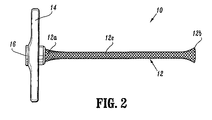
図1、1Aおよび2を見ると、スリーブ構成要素10は、その近位端12aから遠位端12bの管腔15(図1Aを参照のこと)を規定するスリーブ本体12、ならびにスリーブ本体12の近位端12aに作動可能に接続されるハンドル14を備える。好ましくは、スリーブ本体12は、半径方向に拡張可能な編組物(望ましくは、非弾性で、約2mmの内径および約3.5mmの外径を有する)から構築される。ハンドル14は、それを通って形成される通路16(図1Aを参照のこと)を備え、この通路16は、スリーブ本体12の管腔と実質的に整列している。望ましくは、代表的には、コネクタ(図示しない)は、カニューレアセンブリ40上に提供される相補的コネクタを選択的に係合するための通路16の周りに提供される。例えば、相補的コネクタは、差し込みピン取り付け部品(bayonet fitting)などの形態をとり得る。以下により詳細に記載されるように、そこを通る拡張アセンブリの通過は、スリーブ本体12の、代表的に、5mm、10mm、または12mmの最終直径に、半径方向の拡張をもたらす。半径方向に拡張可能なスリーブ10は、米国特許第5,431,676号に記載される詳細に従って構築され得、その開示全体が、本明細書中において参考として援用される。
1, 1A and 2, the
図2に示されるように、スリーブ本体12の遠位端12bは、半径方向外向きにフレア状である。詳細には、スリーブ本体12は、実質的なその全体的な長さに沿って均一な直径を有する中間部分12c、および中間部分12cの直径よりも長い直径を有する遠位端12bを備える。
As shown in FIG. 2, the
図1に示されるように、シース18は、スリーブ本体12を包み、そして/またはそれ以外で覆う。シース18は、スリーブ本体12の長さ全体に延びる。望ましくは、シース18は、プラスチック材料またはエラストマー材料(例えば、ポリウレタン、テトラフルオロエチレン、フッ素化エチレン−プロピレンなど)から作製される。望ましくは、シース18は、手順の間、いくつかの点でシース18の分裂を容易にするために、軸線(一対の薄いかまたは弱い軸溝または線(図示せず))に沿って弱められる。本明細書中で以後にさらに詳細に記載されるように、軸溝によって、シース18は、カニューレアセンブリ40がスリーブ本体12の管腔内に受容される場合に、その長さに沿って分離(divide)または分裂(split)され得、このようにして、スリーブ本体12が半径方向に拡張し得る。
As shown in FIG. 1, the
さらに、図1に示されるように、シース18は、第1の外科手術機器の導入の前に、閉じたフレア状遠位端12b(すなわち、半径方向に非拡張の状態)を維持するのに役立つ。言い換えると、シース18は、遠位端12bがスリーブ本体12の中間部分12cの直径に実質的に等しい直径を有するように、遠位端12bを圧縮する。
Further, as shown in FIG. 1, the
単なる例示として、スリーブ本体12の編組物は、好ましくは、半径方向の拡張が編組物の軸方向の短縮を生じるように、個々の非弾性フィラメント(例えば、ポリアミド繊維、ステンレス鋼など)のメッシュとして形成される。さらに、スリーブ本体12の編組物は、丸いフィラメント、平坦なまたはリボンのフィラメント、四角いフィラメントなどから構成され得る。丸くないフィラメントは、半径方向の拡張を提供するために必要とされる軸力を実質的に減少し得る。フィラメントの幅または直径は、代表的に、約0.002インチ〜約0.25インチであり、通常、約0.005インチ〜約0.010インチである。
By way of example only, the braid of the
ここで、図3を参照すると、アクセスシステムの一部として使用するための気腹針アセンブリは、一般的に、20として示される。気腹針アセンブリ20は、管状針本体22、および管状針本体22と作動可能に係合するスタイレット24を備える。管状針本体22は、その近位端に提供されるハブ25(それから雄型差し込みピンコネクタ26を有する)を備える。スタイレット24は、その近位端に提供されるコネクタ28にバネ装填されている。コネクタ28は、針本体22のハブ25に提供される雌型差し込みピン取り付け部品(図示せず)に受容可能に取り付けられる雄型差し込みピン取り付け部品30を備える。スタイレット24は、さらに、その近位端に提供されるガス注入弁32、およびその遠位端に形成されるポート34を備える。従って、ガス注入ガス(弁32を通して導入される)は、ポート34を通して放出され得る。使用において、スタイレット24は、コネクタ28の差し込みピン取り付け部品30によって管状針本体22内に取り付けられる。スタイレット24の遠位端は、針本体22の遠位端36から延び、そしてスタイレット24は、さらに以下に詳細に記載されるように、針本体22が組織に係合される場合に、針本体22内に引っ込められる。
Referring now to FIG. 3, a pneumoperitoneal needle assembly for use as part of an access system is generally indicated as 20. The
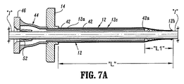
ここで、図4を参照すると、アクセスシステムの一部として使用のためのカニューレアセンブリは、一般的に40として示される。カニューレアセンブリ40は、カニューレ管42、カニューレ管42に接続可能なカニューレハブ44、およびカニューレハブ44に取り外し可能に接続可能な弁キャップ46を備える。カニューレ管42は、その近位端にネジ山付きコネクタ48を備え、これは、カニューレハブ44の遠位端に提供される取り付け部品50に取り外し可能に固定され得るかまたは接続され得る。弁キャップ46は、望ましくは、気体停止弁要素52を備え、カニューレハブ44の近位端に提供される雄型差し込みピン取り付け部品54と嵌合するように構成される。第2の円板弁(disk valve)要素56は、気体停止弁要素52と直列に取り付けられ得、外科手術機器がカニューレアセンブリ40を通して導入される場合に、外科手術機器(図示せず)の外面に係合する。弁要素56は、一般的に、比較的大きな機器(例えば、約12mmの直径を有する機器)のための大きさである。縮小要素58は、比較的小さな機器(例えば、約10mmの直径を有する機器)を収容するために、弁要素56のポートのサイズを縮小するために提供され得る。
Referring now to FIG. 4, a cannula assembly for use as part of an access system is indicated generally as 40.
ここで、図5を参照して、アクセスシステムの一部として使用するための閉塞具は、一般的に、60として示される。閉塞具60は、一般的に、シャフト62、テーパー状の遠位端64、およびハンドル66を備える。閉塞具60は、以下に記載されるように使用するための拡張アセンブリを形成するために、カニューレアセンブリ40の中心管腔内に配置されることが意図される。
Referring now to FIG. 5, an obturator for use as part of an access system is generally indicated as 60. The
ここで、図6を参照して、半径方向に拡張可能なスリーブ構成要素10は、カニューレアセンブリ40と作動可能に関連して示される。詳細には、カニューレアセンブリ40のカニューレ管42は、拡張可能なスリーブ構成要素10のスリーブ本体12の管腔内に完全に挿入されている。望ましくは、スリーブ本体12は、カニューレ管42が拡張可能な
スリーブ構成要素10内に完全に挿入された場合に、カニューレ管42の長さよりも長い長さ「L」を有する。この様式において、スリーブ本体12の遠位端12bは、カニューレ管42の遠位縁部42aを超えて遠位に延びる。望ましくは、スリーブ本体12の長さ「L」は、カニューレ管42が拡張可能なスリーブ構成要素10内に完全に挿入された場合に、カニューレ管42の遠位縁部42aから軸距離「L1」の間隔を空けて配置されるような長さである。
Referring now to FIG. 6, the radially
図7を参照すると、スリーブ本体12のフレア状の遠位端12bは、カニューレアセンブリ40のカニューレ管42および拡張可能なスリーブ構成要素10のスリーブ本体12内に導入され、それを通って延びる機器「I」の表面に対して機器シールを効果的に形成し、そして/または作動する。スリーブ本体12のフレア状の遠位端12bは、カニューレアセンブリ40から、特に、拡張可能なスリーブ構成要素のスリーブ本体12から、機器「I」の除去を容易にするために、提供される。
Referring to FIG. 7, the flared
スリーブ本体12の遠位端12bが好ましくは、フレア状で提供される間、スリーブ本体12の遠位端12bが、機器シールを作り出し、そして/または作用するために、フレアなどを備える必要がないことが、本開示の範囲内である。
While the
望ましくは、図4、6および7に示されるように、カニューレハブ44の気体停止弁要素52は、ダックビルまたは「ゼロ」バルブの形態をとり得る。弁要素52は、遠位端で交差して隣接面(abutment face)を規定する2つの平坦なテーパー状部分を備え得る。平坦なテーパー状部分は、それぞれ、機器「I」の通過を容易にするために、1つ以上の内側に向いた長手方向に配向したリブを備え得る。隣接面は、弁要素52を通る機器「I」の通過を可能にするが、機器「I」が無い場合、特に、カニューレアセンブリ40がガス注入される体腔内に挿入される場合、隣接面は、ガス注入腔を周囲の環境から分離する気密シールを形成する。弁要素52はまた、弁要素52を安定化させるために、少なくとも1つ、好ましくは、2つの強化リブ(図示せず)を備える。リブは、機器「I」と係合して、弁要素52のスリットを通って機器「I」をガイドし、機器「I」の先端によって弁要素52を貫通することを妨げるように配置される。弁要素のより詳細な考察について、米国特許第5,603,702号に対して参照がなされ得、この内容全体が、参考として本明細書中で援用される。
Desirably, as shown in FIGS. 4, 6 and 7, the gas
図8〜13をここで参照して、アクセスシステムの半径方向に拡張可能なスリーブ構成要素10の使用が、詳細に記載される。最初に、図8に示されるように、半径方向に拡張可能なスリーブ構成要素10(そこに挿入される気腹針20を有する)は、針20の鋭い遠位端36を組織に係合させ、そして半径方向に拡張可能なスリーブ構成要素10のスリーブ本体12が組織を横切って延びるまで、アセンブリ(例えば、針20と作動可能に連結された拡張可能スリーブ構成要素10)を進めることによって、患者の腹部「A」(または他の体の位置)と通して導入される。
Referring now to FIGS. 8-13, the use of the radially
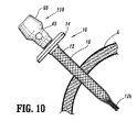
図9に示されるように、針20は、拡張可能スリーブ構成要素10から取り除かれ、拡張アセンブリ110(作動可能に関連した閉塞具60を有するカニューレアセンブリ40を備える)は、半径方向に拡張可能なスリーブ構成要素10を通して導入される。半径方向に拡張可能なスリーブ構成要素10内への拡張アセンブリ110の導入は、スリーブ本体12の半径方向の拡張を生じる(図10を参照のこと)。このようにすることにおいて、シース18は、軸溝(図示せず)の長さに沿って分離または分裂される。さらに、半径方向拡張スリーブ本体12に対する拡張可能スリーブ構成要素内への拡張スリーブ110の挿入は、スリーブ本体12の軸方向の短縮化を生じ、これによって、アンカー拡張アセンブリ110の適所の配置を助け、そして拡張アセンブリ110の外部の組織に対するシールを助ける。
As shown in FIG. 9, the
上記のように、拡張アセンブリ110が半径方向に拡張可能なスリーブ構成要素10内に完全に挿入される場合、カニューレ管42の遠位縁部42aは、スリーブ本体12の遠位端12bを超えて延びない。望ましくは、スリーブ本体12は、拡張アセンブリ110が拡張可能スリーブ構成要素10のスリーブ本体12内に完全に挿入される場合、閉塞具60およびカニューレ管40がスリーブ本体12の遠位端12bを半径方向に拡張せず、従って、シース18の遠位端を分裂して開かないのに十分な長さ「L」を有する。
As described above, when the
図11に示されるように、次いで、閉塞具60は、カニューレアセンブリ40および半径方向に拡張可能なスリーブ10から取り除かれ得、アクセスカニューレを腹壁「A」を通して残す。図12に示すように、閉塞具60が取り除かれ、外科手術機器「I」(例えば、外科手術用グラスパー、ステープラー、タッカー、ファスナーアプライヤーなど)が、カニューレアセンブリ40および半径方向に拡張可能なスリーブ構成要素10を通して、腹腔内に導入され得る。望ましくは、機器「I」は、機器「I」のエンドエフェクタがカニューレ管42の遠位縁部42aを超え、そして拡張可能なスリーブ構成要素10のスリーブ本体12の遠位端12bを超えて拡張可能である。スリーブ本体12の遠位端12bを通る機器「I」の導入は、スリーブ本体の半径方向の拡張を生じ、従って、シース18の遠位端の分離および/または分裂を生じる。シース18がその長さ全体に沿って分離され、ここで、望ましい場合、図13に示されるように、切開の表面と拡張可能スリーブ本体10のスリーブ本体12との間から、シース18を引き抜き、取り除くことが可能である。
As shown in FIG. 11, the
図12を参照して、スリーブ本体12の遠位端12bは、機器「I」の外面に対して機器シールとして作用し、これによって、カニューレ管42を通るガス注入流体の漏れまたは通過を減少させる。このような流体密なシールは、腹腔鏡手順において特に有利である。
Referring to FIG. 12, the
図13を参照して、外科手術手順の実行において外科手術機器「I」の使用に続いて、外科手術機器「I」は、拡張アセンブリ110および半径方向に拡張可能なスリーブ構成要素10から取り除かれ、そして/または引き抜かれ得る。スリーブ本体12のフレア状の遠位端12bは、拡張アセンブリ110および半径方向に拡張可能なスリーブ構成要素10からの外科手術機器の取り除き、および/または引き抜きを容易にする。さらに、スリーブ本体12の遠位端12bは、腹腔からの組織または器官の試料の取り除きおよび/または引き抜きを容易にするために、漏斗のように作用し得る。
Referring to FIG. 13, following use of surgical instrument “I” in performing a surgical procedure, surgical instrument “I” is removed from
本開示は、狭い直径の構成の間に経皮的にまたはそれ以外で導入され得、そして導入後、より大きな直径の外科手術機器の通過に適応するように半径方向に拡張され得るアクセスシステムに関する。本開示の局面に従って、アクセスシステムとともに使用される、半径方向に拡張可能なスリーブ構成要素が提供される。スリーブ構成要素は、ハンドルであって、それを通る通路を有するハンドル;およびスリーブ本体であって、ハンドルに接続される近位端、遠位端、ハンドルの通路と整列した軸管腔を有し、このスリーブ本体が一定の長さを有する、スリーブ本体を備える。スリーブ本体は、半径方向に拡張可能な編組物から構築され、この編組物は、スリーブ本体が半径方向に拡張する場合に、スリーブ本体の長さを軸方向に短くする非弾性フィラメントのメッシュから形成される。スリーブ本体の遠位端は、半径方向外向きにフレア状になっている。 The present disclosure relates to an access system that can be introduced percutaneously or otherwise during a narrow diameter configuration and that can be radially expanded to accommodate passage of larger diameter surgical instruments after introduction. . In accordance with aspects of the present disclosure, a radially expandable sleeve component for use with an access system is provided. The sleeve component is a handle having a passage therethrough; and a sleeve body having a proximal end connected to the handle, a distal end, and an axial lumen aligned with the passage of the handle The sleeve body includes a sleeve body having a certain length. The sleeve body is constructed from a radially expandable braid that is formed from a mesh of inelastic filaments that axially shortens the length of the sleeve body when the sleeve body expands radially. Is done. The distal end of the sleeve body is flared radially outward.
上記は、開示の好ましい実施形態の完全な記載であるが、種々の変更、改変および投下物が使用され得る。従って、上記記載は、添付の特許請求の範囲によって規定される発明の範囲の制限とするべきではない。 While the above is a complete description of the preferred embodiment of the disclosure, various changes, modifications and drops may be used. Therefore, the above description should not be taken as a limitation on the scope of the invention which is defined by the appended claims.
Claims (17)
ハンドルであって、該ハンドルを通る通路を有する、ハンドル;および
スリーブ本体であって、該ハンドルに接続される近位端、遠位端、該ハンドルの通路と整列した軸管腔を有し、該スリーブ本体が一定の長さを有し、該スリーブ本体が、半径方向に拡張可能な編組物から構築され、ここで、該編組物が、該スリーブ本体が半径方向に拡張する場合に該スリーブ本体の長さを軸方向に短くする非弾性フィラメントのメッシュから形成され、該スリーブ本体の遠位端は、半径方向外向きにフレア状になっている、スリーブ本体、
を備える、半径方向に拡張可能なスリーブ構成要素。 A radially expandable sleeve component for use with an access system, the sleeve component comprising:
A handle having a passage through the handle; and a sleeve body having a proximal end connected to the handle, a distal end, an axial lumen aligned with the passage of the handle; The sleeve body has a length, and the sleeve body is constructed from a radially expandable braid, wherein the braid is the sleeve when the sleeve body expands radially. A sleeve body formed from a mesh of inelastic filaments that axially shortens the length of the body, the distal end of the sleeve body flaring radially outwardly;
A radially expandable sleeve component comprising:
半径方向に拡張可能なスリーブ構成要素であって、以下:
ハンドルであって、該ハンドルを通る通路を有する、ハンドル;および
スリーブ本体であって、該ハンドルに接続される近位端、遠位端、該ハンドルの通路と整列した軸管腔を有し、該スリーブ本体が一定の長さを有し、該スリーブ本体の遠位端は、半径方向外向きにフレア状になっている、スリーブ本体、
を備える、半径方向に拡張可能なスリーブ構成要素;ならびに
カニューレ管であって、該カニューレ管が、近位端、遠位端、および該カニューレ管を通って延びる管腔を備え、該カニューレ管が、半径方向に拡張可能なスリーブ構成要素のハンドルの開口部中に受け入れられる大きさであり、該カニューレ管が、該カニューレ管が該半径方向に拡張可能なスリーブ構成要素のスリーブ本体中に完全に挿入された場合、該スリーブ本体の長さよりも短い長さを有する、カニューレ管、
を備える、アクセスシステム。 Access system, the following:
A radially expandable sleeve component comprising:
A handle having a passage through the handle; and a sleeve body having a proximal end connected to the handle, a distal end, an axial lumen aligned with the passage of the handle; The sleeve body has a length, and the distal end of the sleeve body is flared radially outwardly;
A radially expandable sleeve component; and a cannula tube, the cannula tube comprising a proximal end, a distal end, and a lumen extending through the cannula tube, the cannula tube , Sized to be received in the opening of the handle of the radially expandable sleeve component, wherein the cannula tube is fully within the sleeve body of the radially expandable sleeve component. A cannula tube having a length shorter than the length of the sleeve body when inserted,
An access system comprising:
半径方向に拡張可能なスリーブ構成要素であって、以下:
ハンドルであって、それを通る通路を有するハンドル;および
スリーブ本体であって、該スリーブ本体が、該ハンドルに接続される近位端、遠位端、該ハンドルの通路と整列した軸管腔を有し、該スリーブ本体が一定の長さを有し、ここで、該スリーブ本体の遠位端が、半径方向内側にテーパー状である、スリーブ本体、
を備える、半径方向に拡張可能なスリーブ構成要素;ならびに
カニューレ管であって、該カニューレ管が、近位端、遠位端、および該カニューレ管を通って延びる管腔を備え、該カニューレ管が、半径方向に拡張可能なスリーブ構成要素のハンドルの開口部中に受け入れられる大きさであり、該カニューレ管が、該カニューレ管が該半径方向に拡張可能なスリーブ構成要素のスリーブ本体中に完全に挿入された場合、該スリーブ本体の長さよりも短い長さを有し、その結果、該スリーブ本体のテーパー状の遠位端が、半径方向に拡張可能なスリーブ構成要素中に挿入される機器と係合する、カニューレ管、
を備える、アクセスシステム。 Access system, the following:
A radially expandable sleeve component comprising:
A handle having a passage therethrough; and a sleeve body, the sleeve body having a proximal end connected to the handle, a distal end, and an axial lumen aligned with the passage of the handle. A sleeve body, wherein the sleeve body has a length, wherein a distal end of the sleeve body is tapered radially inward;
A radially expandable sleeve component; and a cannula tube, the cannula tube comprising a proximal end, a distal end, and a lumen extending through the cannula tube, the cannula tube , Sized to be received in the opening of the handle of the radially expandable sleeve component, wherein the cannula tube is fully within the sleeve body of the radially expandable sleeve component. An instrument that, when inserted, has a length that is less than the length of the sleeve body so that the tapered distal end of the sleeve body is inserted into a radially expandable sleeve component; Engage, cannula tube,
An access system comprising:
管状針;および
該管状針内に取り外し可能に受け入れ可能な内部スタイレット
を備える、アクセスシステム。 12. The access system according to claim 11, further comprising an insufflation needle, wherein the insufflation needle:
An access system comprising: a tubular needle; and an internal stylet removably receivable within the tubular needle.
Applications Claiming Priority (1)
| Application Number | Priority Date | Filing Date | Title |
|---|---|---|---|
| US11/081,766 US20060212062A1 (en) | 2005-03-16 | 2005-03-16 | Radially expandable access system including trocar seal |
Related Child Applications (1)
| Application Number | Title | Priority Date | Filing Date |
|---|---|---|---|
| JP2011156140A Division JP2011251134A (en) | 2005-03-16 | 2011-07-14 | Radially expandable access system including trocar seal |
Publications (1)
| Publication Number | Publication Date |
|---|---|
| JP2006255408A true JP2006255408A (en) | 2006-09-28 |
Family
ID=36596738
Family Applications (2)
| Application Number | Title | Priority Date | Filing Date |
|---|---|---|---|
| JP2006047567A Pending JP2006255408A (en) | 2005-03-16 | 2006-02-23 | Radially expandable access system equipped with trocar seal |
| JP2011156140A Pending JP2011251134A (en) | 2005-03-16 | 2011-07-14 | Radially expandable access system including trocar seal |
Family Applications After (1)
| Application Number | Title | Priority Date | Filing Date |
|---|---|---|---|
| JP2011156140A Pending JP2011251134A (en) | 2005-03-16 | 2011-07-14 | Radially expandable access system including trocar seal |
Country Status (7)
| Country | Link |
|---|---|
| US (1) | US20060212062A1 (en) |
| EP (3) | EP2316360A1 (en) |
| JP (2) | JP2006255408A (en) |
| AU (1) | AU2006200926B2 (en) |
| CA (1) | CA2539264A1 (en) |
| DE (1) | DE602006006732D1 (en) |
| ES (2) | ES2326092T3 (en) |
Cited By (7)
| Publication number | Priority date | Publication date | Assignee | Title |
|---|---|---|---|---|
| JP2009090110A (en) * | 2007-10-05 | 2009-04-30 | Tyco Healthcare Group Lp | Expanding seal anchor for single incision surgery |
| WO2009154192A1 (en) * | 2008-06-19 | 2009-12-23 | 国立大学法人大阪大学 | Lumenal wall puncturing overtube |
| JP2010005399A (en) * | 2008-06-25 | 2010-01-14 | Tyco Healthcare Group Lp | Access cannula having hinge restrictor |
| JP2010005388A (en) * | 2008-06-25 | 2010-01-14 | Tyco Healthcare Group Lp | Access assembly |
| JP2010518901A (en) * | 2007-02-20 | 2010-06-03 | タイコ ヘルスケア グループ リミテッド パートナーシップ | Flexible cannula with seal |
| JP2010527640A (en) * | 2007-02-20 | 2010-08-19 | タイコ ヘルスケア グループ リミテッド パートナーシップ | Flexible outer cannula sheath |
| JP2016093563A (en) * | 2009-08-31 | 2016-05-26 | アプライド メディカル リソーシーズ コーポレイション | Multifunctional access system for surgery |
Families Citing this family (68)
| Publication number | Priority date | Publication date | Assignee | Title |
|---|---|---|---|---|
| JPS6357287A (en) * | 1986-08-29 | 1988-03-11 | Mitsui Toatsu Chem Inc | Optical recording medium |
| US20060247500A1 (en) | 2005-04-08 | 2006-11-02 | Voegele James W | Surgical access device |
| US9005116B2 (en) | 2006-04-05 | 2015-04-14 | Ethicon Endo-Surgery, Inc. | Access device |
| US8821391B2 (en) | 2009-03-06 | 2014-09-02 | Ethicon Endo-Surgery, Inc. | Methods and devices for providing access into a body cavity |
| US8926506B2 (en) | 2009-03-06 | 2015-01-06 | Ethicon Endo-Surgery, Inc. | Methods and devices for providing access into a body cavity |
| US8357085B2 (en) | 2009-03-31 | 2013-01-22 | Ethicon Endo-Surgery, Inc. | Devices and methods for providing access into a body cavity |
| US8430811B2 (en) | 2008-09-30 | 2013-04-30 | Ethicon Endo-Surgery, Inc. | Multiple port surgical access device |
| US8251900B2 (en) | 2009-03-06 | 2012-08-28 | Ethicon Endo-Surgery, Inc. | Surgical access devices and methods providing seal movement in predefined paths |
| US8206294B2 (en) * | 2008-09-30 | 2012-06-26 | Ethicon Endo-Surgery, Inc. | Surgical access device with flexible seal channel |
| US8485970B2 (en) | 2008-09-30 | 2013-07-16 | Ethicon Endo-Surgery, Inc. | Surgical access device |
| US8425410B2 (en) | 2008-09-30 | 2013-04-23 | Ethicon Endo-Surgery, Inc. | Surgical access device with protective element |
| US8961406B2 (en) | 2009-03-06 | 2015-02-24 | Ethicon Endo-Surgery, Inc. | Surgical access devices and methods providing seal movement in predefined movement regions |
| US7762990B2 (en) | 2007-05-24 | 2010-07-27 | Tyco Healthcare Group Lp | Surgical access apparatus with centering mechanism |
| US8372131B2 (en) * | 2007-07-16 | 2013-02-12 | Power Ten , LLC | Surgical site access system and deployment device for same |
| US20090024158A1 (en) * | 2007-07-16 | 2009-01-22 | Zimmer Spine, Inc. | Access Port Expander And Method |
| US20090204081A1 (en) * | 2008-02-13 | 2009-08-13 | Depuy Mitek, Inc. | Compression expanded cannula |
| US8021339B2 (en) | 2008-07-01 | 2011-09-20 | Tyco Healthcare Group Lp | Surgical portal apparatus with centering mechanism |
| US8328761B2 (en) | 2008-09-30 | 2012-12-11 | Ethicon Endo-Surgery, Inc. | Variable surgical access device |
| US9737334B2 (en) | 2009-03-06 | 2017-08-22 | Ethicon Llc | Methods and devices for accessing a body cavity |
| US8353824B2 (en) | 2009-03-31 | 2013-01-15 | Ethicon Endo-Surgery, Inc. | Access method with insert |
| US8945163B2 (en) | 2009-04-01 | 2015-02-03 | Ethicon Endo-Surgery, Inc. | Methods and devices for cutting and fastening tissue |
| US8419635B2 (en) | 2009-04-08 | 2013-04-16 | Ethicon Endo-Surgery, Inc. | Surgical access device having removable and replaceable components |
| US8257251B2 (en) | 2009-04-08 | 2012-09-04 | Ethicon Endo-Surgery, Inc. | Methods and devices for providing access into a body cavity |
| US8137267B2 (en) | 2009-04-08 | 2012-03-20 | Ethicon Endo-Surgery, Inc. | Retractor with flexible sleeve |
| US8361109B2 (en) | 2009-06-05 | 2013-01-29 | Ethicon Endo-Surgery, Inc. | Multi-planar obturator with foldable retractor |
| US9078695B2 (en) | 2009-06-05 | 2015-07-14 | Ethicon Endo-Surgery, Inc. | Methods and devices for accessing a body cavity using a surgical access device with modular seal components |
| US8241209B2 (en) | 2009-06-05 | 2012-08-14 | Ethicon Endo-Surgery, Inc. | Active seal components |
| US8465422B2 (en) | 2009-06-05 | 2013-06-18 | Ethicon Endo-Surgery, Inc. | Retractor with integrated wound closure |
| US8795163B2 (en) | 2009-06-05 | 2014-08-05 | Ethicon Endo-Surgery, Inc. | Interlocking seal components |
| US8033995B2 (en) | 2009-06-05 | 2011-10-11 | Ethicon Endo-Surgery, Inc. | Inflatable retractor with insufflation and method |
| US8475490B2 (en) | 2009-06-05 | 2013-07-02 | Ethicon Endo-Surgery, Inc. | Methods and devices for providing access through tissue to a surgical site |
| US8409084B2 (en) | 2009-08-31 | 2013-04-02 | Covidien Lp | Surgical portal apparatus including gear and lockout assembly |
| US9474540B2 (en) | 2009-10-08 | 2016-10-25 | Ethicon-Endo-Surgery, Inc. | Laparoscopic device with compound angulation |
| US8926508B2 (en) | 2009-12-17 | 2015-01-06 | Covidien Lp | Access assembly with dual anchor and seal capabilities |
| US8562592B2 (en) | 2010-05-07 | 2013-10-22 | Ethicon Endo-Surgery, Inc. | Compound angle laparoscopic methods and devices |
| US9226760B2 (en) | 2010-05-07 | 2016-01-05 | Ethicon Endo-Surgery, Inc. | Laparoscopic devices with flexible actuation mechanisms |
| US8460337B2 (en) | 2010-06-09 | 2013-06-11 | Ethicon Endo-Surgery, Inc. | Selectable handle biasing |
| US8702592B2 (en) | 2010-09-30 | 2014-04-22 | David Allan Langlois | System and method for inhibiting injury to a patient during laparoscopic surgery |
| US20120157783A1 (en) * | 2010-12-20 | 2012-06-21 | Greg Okoniewski | Self deploying bodily opening protector |
| US20130269705A1 (en) | 2012-04-16 | 2013-10-17 | Thomas C. Kochem | Variable stiffness flexure |
| EP2695581B1 (en) | 2012-08-07 | 2019-03-13 | Critical Innovations, LLC | Device for simultaneously documenting and treating tension pneumothorax and/or hemothorax |
| US10646690B2 (en) * | 2012-11-20 | 2020-05-12 | University Of Massachusetts | Flexible surgical sheath and multi-part insertion cannula |
| US20140200591A1 (en) * | 2013-01-11 | 2014-07-17 | Hologic, Inc. | Cervical sealing apparatus |
| US9333111B2 (en) | 2013-02-04 | 2016-05-10 | Hologic, Inc. | Fundus bumper mechanical reference for easier mechanism deployment |
| US9895192B2 (en) | 2013-03-13 | 2018-02-20 | Hologic, Inc. | Intrauterine treatment device with articulating array |
| US10986984B2 (en) | 2013-03-13 | 2021-04-27 | Spiway Llc | Surgical tissue protection sheath |
| US11039735B2 (en) | 2013-03-13 | 2021-06-22 | Spiway Llc | Surgical tissue protection sheath |
| CA2905932C (en) * | 2013-03-14 | 2017-12-12 | Salvatore Castro | Dilating cannula with radially expandable flange and method of using the same |
| US10046147B2 (en) | 2013-12-26 | 2018-08-14 | Critical Innovations, LLC | Percutaneous access pathway system and method |
| JP2017515593A (en) * | 2014-05-13 | 2017-06-15 | ビコール メディカル,インコーポレイティド | Guide system attachment for a surgical introducer |
| US10279124B2 (en) * | 2015-01-22 | 2019-05-07 | Aesynt Incorporated | Expanding needle device and method of expansion for the transfer of fluids |
| US10603195B1 (en) | 2015-05-20 | 2020-03-31 | Paul Sherburne | Radial expansion and contraction features of medical devices |
| US9744024B2 (en) | 2015-08-06 | 2017-08-29 | Kp Medcure, Inc. | Axial lengthening thrombus capture system |
| US9999493B2 (en) | 2015-08-06 | 2018-06-19 | Kp Medcure, Inc. | Axial lengthening thrombus capture system |
| EP3721818A1 (en) | 2015-08-06 | 2020-10-14 | KP Medcure, Inc. | Axially lengthening thrombus capture system |
| US10548631B2 (en) * | 2016-03-04 | 2020-02-04 | Boston Scientific Scimed Inc. | Introducer with expandable capabilities |
| WO2017214496A1 (en) | 2016-06-10 | 2017-12-14 | University Of Virginia Patent Foundation | Port apparatus and sheath device for electrocautery and related methods thereof |
| US10675114B2 (en) * | 2016-09-26 | 2020-06-09 | Spiway Llc | Access sheath for brain surgery |
| US10543016B2 (en) | 2016-11-07 | 2020-01-28 | Vycor Medical, Inc. | Surgical introducer with guidance system receptacle |
| US10376258B2 (en) | 2016-11-07 | 2019-08-13 | Vycor Medical, Inc. | Surgical introducer with guidance system receptacle |
| CA2993590A1 (en) | 2017-09-06 | 2019-03-06 | Xpan Inc. | Radially expandable cannula system |
| US10814119B2 (en) | 2017-09-22 | 2020-10-27 | Critical Innovations, LLC | Percutaneous access pathway system |
| SG11202101030UA (en) * | 2018-08-14 | 2021-02-25 | Abiomed Inc | Expandable introducer sheath for medical device |
| US11583313B1 (en) | 2018-12-06 | 2023-02-21 | Spiway Llc | Surgical access sheath and methods of use |
| CN115175638A (en) | 2019-11-05 | 2022-10-11 | 瓦斯科尔勒治疗股份有限公司 | Axially elongated thrombus capture system, tensioning system, and expandable funnel catheter |
| JP2023517678A (en) | 2020-03-13 | 2023-04-26 | エックスパン インコーポレイテッド | RADIALLY EXPANDABLE CANNULA DEVICES AND SYSTEMS AND METHODS FOR USING THEM |
| US11903620B2 (en) * | 2021-01-25 | 2024-02-20 | Medos International Sarl | Flexible sleeve for bone fixation, and related systems and methods |
| US20230128242A1 (en) * | 2021-10-26 | 2023-04-27 | Medos International Sarl | Flexible surgical access port |
Citations (1)
| Publication number | Priority date | Publication date | Assignee | Title |
|---|---|---|---|---|
| US5643282A (en) * | 1994-08-22 | 1997-07-01 | Kieturakis; Maciej J. | Surgical instrument and method for removing tissue from an endoscopic workspace |
Family Cites Families (94)
| Publication number | Priority date | Publication date | Assignee | Title |
|---|---|---|---|---|
| US1213001A (en) * | 1916-05-02 | 1917-01-16 | Ralph S Philips | Therapeutic apparatus. |
| US2548602A (en) * | 1948-04-09 | 1951-04-10 | Greenburg Leonard | Inflatable dilator |
| US3509883A (en) * | 1967-11-29 | 1970-05-05 | Gen Electric | Expanding cannula |
| US3742958A (en) * | 1971-04-21 | 1973-07-03 | C Rundles | Suprapubic catheter inserter |
| US3789852A (en) * | 1972-06-12 | 1974-02-05 | S Kim | Expandable trochar, especially for medical purposes |
| GB1443828A (en) * | 1973-05-14 | 1976-07-28 | Greenhalgh R M | Catheters |
| JPS5239596B2 (en) * | 1974-04-04 | 1977-10-06 | ||
| US4141364A (en) * | 1977-03-18 | 1979-02-27 | Jorge Schultze | Expandable endotracheal or urethral tube |
| US4589686A (en) * | 1980-11-05 | 1986-05-20 | Mcgrew Stephen P | Anticounterfeiting method and device |
| US4411655A (en) * | 1981-11-30 | 1983-10-25 | Schreck David M | Apparatus and method for percutaneous catheterization |
| SE445884B (en) * | 1982-04-30 | 1986-07-28 | Medinvent Sa | DEVICE FOR IMPLANTATION OF A RODFORM PROTECTION |
| US4447237A (en) * | 1982-05-07 | 1984-05-08 | Dow Corning Corporation | Valving slit construction and cooperating assembly for penetrating the same |
| US4479497A (en) * | 1982-11-12 | 1984-10-30 | Thomas J. Fogarty | Double lumen dilatation catheter |
| US4774091A (en) * | 1983-10-14 | 1988-09-27 | Sumitomo Pharmaceuticals Company, Ltd. | Long-term sustained-release preparation |
| US4581025A (en) * | 1983-11-14 | 1986-04-08 | Cook Incorporated | Sheath |
| GB8424436D0 (en) * | 1984-09-27 | 1984-10-31 | Pratt Int Ltd Burnerd | Surgical appliance |
| US4753626A (en) * | 1985-02-22 | 1988-06-28 | Gkn Automotive Components Inc. | Constant velocity universal joint and apparatus embodying the same |
| GB8513702D0 (en) * | 1985-05-30 | 1985-07-03 | Gill S S | Expansible trocar |
| US4738666A (en) * | 1985-06-11 | 1988-04-19 | Genus Catheter Technologies, Inc. | Variable diameter catheter |
| US4601713A (en) * | 1985-06-11 | 1986-07-22 | Genus Catheter Technologies, Inc. | Variable diameter catheter |
| US4610668A (en) * | 1985-10-02 | 1986-09-09 | Fleig John A | Preselected multiple dosage syringe |
| US4650466A (en) * | 1985-11-01 | 1987-03-17 | Angiobrade Partners | Angioplasty device |
| US4733665C2 (en) * | 1985-11-07 | 2002-01-29 | Expandable Grafts Partnership | Expandable intraluminal graft and method and apparatus for implanting an expandable intraluminal graft |
| JPS63158064A (en) * | 1986-12-23 | 1988-07-01 | テルモ株式会社 | Blood vessel dilating catheter |
| US4772266A (en) * | 1987-05-04 | 1988-09-20 | Catheter Technology Corp. | Catheter dilator/sheath assembly and method |
| US4798193A (en) * | 1987-05-18 | 1989-01-17 | Thomas J. Fogarty | Protective sheath instrument carrier |
| JPS642662A (en) * | 1987-06-25 | 1989-01-06 | Nippon Sherwood Kk | Easy split plastic cannula excellent in stability |
| DE3802158A1 (en) * | 1987-08-11 | 1989-02-23 | Hoechst Ag | DEVICE FOR APPLICATION OF IMPLANTS |
| US4921479A (en) * | 1987-10-02 | 1990-05-01 | Joseph Grayzel | Catheter sheath with longitudinal seam |
| US5487739A (en) * | 1987-11-17 | 1996-01-30 | Brown University Research Foundation | Implantable therapy systems and methods |
| US4869717A (en) * | 1988-04-25 | 1989-09-26 | Adair Edwin Lloyd | Gas insufflation needle with instrument port |
| US4896669A (en) * | 1988-08-31 | 1990-01-30 | Meadox Medicals, Inc. | Dilatation catheter |
| US4846791A (en) * | 1988-09-02 | 1989-07-11 | Advanced Medical Technology & Development Corp. | Multi-lumen catheter |
| US5234425A (en) * | 1989-03-03 | 1993-08-10 | Thomas J. Fogarty | Variable diameter sheath method and apparatus for use in body passages |
| US5112304A (en) * | 1989-03-17 | 1992-05-12 | Angeion Corporation | Balloon catheter |
| US5116318A (en) * | 1989-06-06 | 1992-05-26 | Cordis Corporation | Dilatation balloon within an elastic sleeve |
| US5222938A (en) * | 1989-09-15 | 1993-06-29 | Interventional Thermodynamics, Inc. | Method for thermal ablation of hollow body organs |
| US5100388A (en) * | 1989-09-15 | 1992-03-31 | Interventional Thermodynamics, Inc. | Method and device for thermal ablation of hollow body organs |
| US5045056A (en) * | 1989-09-15 | 1991-09-03 | Behl Robert S | Method and device for thermal ablation of hollow body organs |
| US4986830A (en) * | 1989-09-22 | 1991-01-22 | Schneider (U.S.A.) Inc. | Valvuloplasty catheter with balloon which remains stable during inflation |
| US5122122A (en) * | 1989-11-22 | 1992-06-16 | Dexide, Incorporated | Locking trocar sleeve |
| GB2240718A (en) * | 1990-02-09 | 1991-08-14 | Hundon Forge Ltd | Implanting device with needle cover |
| GB2240926A (en) * | 1990-02-14 | 1991-08-21 | Steven Streatfield Gill | An expansible cannula |
| US5078736A (en) * | 1990-05-04 | 1992-01-07 | Interventional Thermodynamics, Inc. | Method and apparatus for maintaining patency in the body passages |
| US5201756A (en) * | 1990-06-20 | 1993-04-13 | Danforth Biomedical, Inc. | Radially-expandable tubular elements for use in the construction of medical devices |
| US5188602A (en) * | 1990-07-12 | 1993-02-23 | Interventional Thermodynamics, Inc. | Method and device for delivering heat to hollow body organs |
| US5250025A (en) * | 1990-08-15 | 1993-10-05 | Intramed Laboratories | Percutaneous access catheter and method of use |
| US5391183A (en) * | 1990-09-21 | 1995-02-21 | Datascope Investment Corp | Device and method sealing puncture wounds |
| US5222971A (en) * | 1990-10-09 | 1993-06-29 | Scimed Life Systems, Inc. | Temporary stent and methods for use and manufacture |
| JP3269556B2 (en) * | 1990-11-20 | 2002-03-25 | インナーダイン インコーポレイティド | Apparatus for forming percutaneous perforations in body cavities |
| US5158545A (en) * | 1991-05-02 | 1992-10-27 | Brigham And Women's Hospital | Diameter expansion cannula |
| US5183464A (en) * | 1991-05-17 | 1993-02-02 | Interventional Thermodynamics, Inc. | Radially expandable dilator |
| WO1992020290A1 (en) * | 1991-05-17 | 1992-11-26 | Innerdyne Medical, Inc. | Method and device for thermal ablation |
| US5542928A (en) * | 1991-05-17 | 1996-08-06 | Innerdyne, Inc. | Method and device for thermal ablation having improved heat transfer |
| CA2109955A1 (en) * | 1991-05-24 | 1992-11-26 | Toru Hayakawa | Equipment for intracerebral administration of preparations |
| US5330432A (en) * | 1991-12-06 | 1994-07-19 | Inbae Yoon | Retractable safety penetrating instrument |
| US5403278A (en) * | 1992-04-15 | 1995-04-04 | Datascope Investment Corp. | Device and method for treating hematomas and false aneurysms |
| US5250033A (en) * | 1992-10-28 | 1993-10-05 | Interventional Thermodynamics, Inc. | Peel-away introducer sheath having proximal fitting |
| US5316360A (en) * | 1993-01-05 | 1994-05-31 | Feikema Orville A | Automobile sun visor |
| US5674240A (en) * | 1993-02-04 | 1997-10-07 | Peter M. Bonutti | Expandable cannula |
| US5320611A (en) * | 1993-02-04 | 1994-06-14 | Peter M. Bonutti | Expandable cannula having longitudinal wire and method of use |
| US5431676A (en) * | 1993-03-05 | 1995-07-11 | Innerdyne Medical, Inc. | Trocar system having expandable port |
| US5814058A (en) * | 1993-03-05 | 1998-09-29 | Innerdyne, Inc. | Method and apparatus employing conformable sleeve for providing percutaneous access |
| US5304119A (en) * | 1993-06-24 | 1994-04-19 | Monsanto Company | Instrument for injecting implants through animal hide |
| US5630822A (en) * | 1993-07-02 | 1997-05-20 | General Surgical Innovations, Inc | Laparoscopic tissue removal device |
| US5453094A (en) * | 1993-09-17 | 1995-09-26 | Minnesota Mining And Manufacturing Company | Kit assembly for use during a laparoscopic surgical procedure |
| US5392766A (en) * | 1993-10-06 | 1995-02-28 | Innerdyne Medical, Inc. | System and method for cleaning viewing scope lenses |
| DE4401237C2 (en) * | 1994-01-18 | 1997-06-05 | Ruesch Willy Ag | Trocar device |
| US5407430A (en) * | 1994-03-21 | 1995-04-18 | Peters; Michael J. | Intravenous catheter |
| US5484403A (en) * | 1994-04-05 | 1996-01-16 | Avid Marketing, Inc. | Hypodermic syringe for implanting solid objects |
| US5454790A (en) * | 1994-05-09 | 1995-10-03 | Innerdyne, Inc. | Method and apparatus for catheterization access |
| US5540658A (en) * | 1994-06-27 | 1996-07-30 | Innerdyne, Inc. | Transcervical uterine access and sealing device |
| US5603702A (en) * | 1994-08-08 | 1997-02-18 | United States Surgical Corporation | Valve system for cannula assembly |
| US5460170A (en) * | 1994-08-23 | 1995-10-24 | Hammerslag; Julius G. | Adjustable surgical retractor |
| US5643227A (en) * | 1995-01-19 | 1997-07-01 | Stevens; Robert C. | Hemostasis cannula valve apparatus and method of using same |
| US5807338A (en) * | 1995-10-20 | 1998-09-15 | United States Surgical Corporation | Modular trocar system and methods of assembly |
| US6451041B1 (en) * | 1996-02-29 | 2002-09-17 | Stephen P. Moenning | Apparatus for protecting a port site opening in the wall of a body cavity and reducing electrosurgical injuries |
| US5814026A (en) * | 1996-03-19 | 1998-09-29 | Yoon; Inbae | Endoscopic portal having a universal seal and methods for introducing instruments therethrough |
| US5788676A (en) * | 1996-03-25 | 1998-08-04 | Yoon; Inbae | Endoscopic portal having multiple universal seals and method of introducing instruments therethrough |
| US5713867A (en) * | 1996-04-29 | 1998-02-03 | Medtronic, Inc. | Introducer system having kink resistant splittable sheath |
| US5820600A (en) * | 1996-05-14 | 1998-10-13 | Innerdyne, Inc. | Adjustable introducer valve |
| US5827319A (en) * | 1996-05-20 | 1998-10-27 | Innerdyne, Inc. | Radially expandable access system having disposable and reusable components |
| US5882345A (en) * | 1996-05-22 | 1999-03-16 | Yoon; Inbae | Expandable endoscopic portal |
| US6066117A (en) * | 1996-06-11 | 2000-05-23 | Endolap, Inc. | Cannula flapper valve assembly |
| US5779697A (en) * | 1997-05-28 | 1998-07-14 | Linvatec Corporation | Arthroscopic cannula with fluid seals |
| US6530923B1 (en) * | 1998-02-10 | 2003-03-11 | Artemis Medical, Inc. | Tissue removal methods and apparatus |
| US6228061B1 (en) * | 1998-02-03 | 2001-05-08 | Imagyn Medical Technologies California, Inc. | Trocar seal system having dual seals |
| US6387095B1 (en) * | 1998-02-09 | 2002-05-14 | Loren R. Kennett | Surgical device comprising a radially expandable non-conductive sheath |
| US5989224A (en) * | 1998-02-23 | 1999-11-23 | Dexide Corporation | Universal seal for use with endoscopic cannula |
| US6095967A (en) * | 1998-03-25 | 2000-08-01 | Manan Medical Products, Inc. | Isotope seeding system that releases radioactive seeds for treatment of cancerous cells |
| US6245052B1 (en) * | 1998-07-08 | 2001-06-12 | Innerdyne, Inc. | Methods, systems, and kits for implanting articles |
| US6595946B1 (en) * | 2000-02-25 | 2003-07-22 | United States Surgical Corporation | Valve assembly |
| AU2002317605B2 (en) * | 2001-08-01 | 2008-09-25 | Covidien Lp | Radially dilatable percutaneous access apparatus with introducer seal in handle |
| WO2003071926A2 (en) * | 2002-02-21 | 2003-09-04 | Persidsky Maxim D | Apparatus and method for making a percutaneous access for port of variable size |
-
2005
- 2005-03-16 US US11/081,766 patent/US20060212062A1/en not_active Abandoned
-
2006
- 2006-02-23 JP JP2006047567A patent/JP2006255408A/en active Pending
- 2006-03-03 AU AU2006200926A patent/AU2006200926B2/en not_active Ceased
- 2006-03-10 CA CA002539264A patent/CA2539264A1/en not_active Abandoned
- 2006-03-13 EP EP10182014A patent/EP2316360A1/en not_active Withdrawn
- 2006-03-13 DE DE602006006732T patent/DE602006006732D1/en active Active
- 2006-03-13 ES ES06005056T patent/ES2326092T3/en active Active
- 2006-03-13 EP EP09006385A patent/EP2098180B1/en not_active Expired - Fee Related
- 2006-03-13 ES ES09006385T patent/ES2386097T3/en active Active
- 2006-03-13 EP EP06005056A patent/EP1702575B1/en not_active Expired - Fee Related
-
2011
- 2011-07-14 JP JP2011156140A patent/JP2011251134A/en active Pending
Patent Citations (1)
| Publication number | Priority date | Publication date | Assignee | Title |
|---|---|---|---|---|
| US5643282A (en) * | 1994-08-22 | 1997-07-01 | Kieturakis; Maciej J. | Surgical instrument and method for removing tissue from an endoscopic workspace |
Cited By (8)
| Publication number | Priority date | Publication date | Assignee | Title |
|---|---|---|---|---|
| JP2010518901A (en) * | 2007-02-20 | 2010-06-03 | タイコ ヘルスケア グループ リミテッド パートナーシップ | Flexible cannula with seal |
| JP2010527640A (en) * | 2007-02-20 | 2010-08-19 | タイコ ヘルスケア グループ リミテッド パートナーシップ | Flexible outer cannula sheath |
| JP2009090110A (en) * | 2007-10-05 | 2009-04-30 | Tyco Healthcare Group Lp | Expanding seal anchor for single incision surgery |
| WO2009154192A1 (en) * | 2008-06-19 | 2009-12-23 | 国立大学法人大阪大学 | Lumenal wall puncturing overtube |
| JP5224298B2 (en) * | 2008-06-19 | 2013-07-03 | 国立大学法人大阪大学 | Lumen wall puncture overtube |
| JP2010005399A (en) * | 2008-06-25 | 2010-01-14 | Tyco Healthcare Group Lp | Access cannula having hinge restrictor |
| JP2010005388A (en) * | 2008-06-25 | 2010-01-14 | Tyco Healthcare Group Lp | Access assembly |
| JP2016093563A (en) * | 2009-08-31 | 2016-05-26 | アプライド メディカル リソーシーズ コーポレイション | Multifunctional access system for surgery |
Also Published As
| Publication number | Publication date |
|---|---|
| EP2098180A1 (en) | 2009-09-09 |
| EP1702575B1 (en) | 2009-05-13 |
| ES2326092T3 (en) | 2009-09-30 |
| EP1702575A3 (en) | 2007-03-21 |
| AU2006200926A1 (en) | 2006-10-05 |
| EP2098180B1 (en) | 2012-06-13 |
| ES2386097T3 (en) | 2012-08-09 |
| CA2539264A1 (en) | 2006-09-16 |
| JP2011251134A (en) | 2011-12-15 |
| EP2316360A1 (en) | 2011-05-04 |
| US20060212062A1 (en) | 2006-09-21 |
| AU2006200926B2 (en) | 2011-07-07 |
| DE602006006732D1 (en) | 2009-06-25 |
| EP1702575A2 (en) | 2006-09-20 |
Similar Documents
| Publication | Publication Date | Title |
|---|---|---|
| EP1702575B1 (en) | Radially expandable access system including trocar seal | |
| JP4279138B2 (en) | Radially inflatable percutaneous access device with introducer seal in handle | |
| US8414483B2 (en) | Methods and devices for providing access into a body cavity | |
| US8357088B2 (en) | Methods and devices for providing access into a body cavity | |
| US8435174B2 (en) | Methods and devices for accessing a body cavity | |
| US8419635B2 (en) | Surgical access device having removable and replaceable components | |
| US8137267B2 (en) | Retractor with flexible sleeve | |
| JP4102421B2 (en) | Trocar system with expandable port | |
| JP5139483B2 (en) | Surgical access device and its manufacture | |
| EP3071131B1 (en) | Exchanger surgical access port assembly | |
| JP2011104378A (en) | Port fixation device | |
| JP2010172694A (en) | Suture management system for surgical portal apparatus including internal tube | |
| US20210299416A1 (en) | Balloon cannula including a plurality of balloons | |
| US20210315607A1 (en) | Detachably mountable camera assembly for a cannula assembly | |
| US20150313632A1 (en) | Obturator with instrument retention | |
| WO2011072100A2 (en) | Methods and devices for providing access into a body cavity |
Legal Events
| Date | Code | Title | Description |
|---|---|---|---|
| A621 | Written request for application examination |
Free format text: JAPANESE INTERMEDIATE CODE: A621 Effective date: 20081225 |
|
| A131 | Notification of reasons for refusal |
Free format text: JAPANESE INTERMEDIATE CODE: A131 Effective date: 20110428 |
|
| A521 | Written amendment |
Free format text: JAPANESE INTERMEDIATE CODE: A523 Effective date: 20110714 |
|
| A131 | Notification of reasons for refusal |
Free format text: JAPANESE INTERMEDIATE CODE: A131 Effective date: 20120220 |
|
| A02 | Decision of refusal |
Free format text: JAPANESE INTERMEDIATE CODE: A02 Effective date: 20120803 |