JP2006255309A - Game machine - Google Patents

Game machine Download PDF

Info

Publication number
JP2006255309A
JP2006255309A JP2005080050A JP2005080050A JP2006255309A JP 2006255309 A JP2006255309 A JP 2006255309A JP 2005080050 A JP2005080050 A JP 2005080050A JP 2005080050 A JP2005080050 A JP 2005080050A JP 2006255309 A JP2006255309 A JP 2006255309A
Authority
JP
Japan
Prior art keywords
ball
opening
winning
variable winning
game ball
Prior art date
Legal status (The legal status is an assumption and is not a legal conclusion. Google has not performed a legal analysis and makes no representation as to the accuracy of the status listed.)
Pending
Application number
JP2005080050A
Other languages
Japanese (ja)
Other versions
JP2006255309A5 (en
Inventor
Takaaki Ichihara
高明 市原
Koji Niimi
好司 新見
Current Assignee (The listed assignees may be inaccurate. Google has not performed a legal analysis and makes no representation or warranty as to the accuracy of the list.)
Daiichi Shokai Co Ltd
Original Assignee
Daiichi Shokai Co Ltd
Priority date (The priority date is an assumption and is not a legal conclusion. Google has not performed a legal analysis and makes no representation as to the accuracy of the date listed.)
Filing date
Publication date
Application filed by Daiichi Shokai Co Ltd filed Critical Daiichi Shokai Co Ltd
Priority to JP2005080050A priority Critical patent/JP2006255309A/en
Publication of JP2006255309A publication Critical patent/JP2006255309A/en
Publication of JP2006255309A5 publication Critical patent/JP2006255309A5/ja
Pending legal-status Critical Current

Links

Images

Abstract

<P>PROBLEM TO BE SOLVED: To provide a game machine capable of preventing upsizing of a variable winning ball device itself by making the rear side of the device as compact as possible. <P>SOLUTION: The upper variable winning ball device 60 comprises a winning hole switch for detecting game balls entered variable winning holes 61a-61d, and a guide passage for guiding the game balls entered the variable winning holes 61a-61d on the rear side of a game board 4. The guide passage has a ball guide part for discharging game balls toward a side of the upper variable winning ball device 60. The winning hole switch has a ball detection hole for detecting the game ball which passes the switch, and the ball detection hole is disposed to compose a part of a passage side wall of the ball guide part. Accordingly, the rear side of the upper variable winning ball device 60 can be made as compact as possible, and upsizing of the device itself can be prevented. <P>COPYRIGHT: (C)2006,JPO&NCIPI

Description

本発明は、遊技盤に区画形成された遊技領域に遊技球を打ち込んで遊技を行う遊技機に関するものである。   The present invention relates to a gaming machine for playing a game by driving a game ball into a game area partitioned on a game board.

従来、一般に、遊技盤に区画形成された遊技領域に遊技球を打ち込んで遊技を行う遊技機の一例としてのパチンコ機には、遊技球の自重によって可変入賞球装置(パチンコ機用入賞玉受口器)の開放機構を作動して可変入賞球装置の入賞口を開放するもの(例えば、特許文献1参照)が提案されている。特許文献1の構成では、遊技球が通過する球通路内に遊技球の自重によって作動する開放レバーを設けると共に、入賞口(打玉入口孔)の開閉部材(揺動玉受片)を開放レバーと連動して設けている。
特開平6−23108号公報(図4)
Conventionally, in general, a pachinko machine as an example of a gaming machine that performs a game by driving a game ball into a game area partitioned on a game board, a variable winning ball device (a prize ball receiving hole for a pachinko machine) In which the winning opening of the variable winning ball apparatus is opened (see, for example, Patent Document 1). In the configuration of Patent Document 1, an opening lever that is actuated by the weight of the game ball is provided in the ball passage through which the game ball passes, and the opening / closing member (swing ball receiving piece) of the winning opening (hitting ball inlet hole) is provided as an opening lever. It is linked with.
JP-A-6-23108 (FIG. 4)

ところで、上記特許文献1の構成では、入賞口に入った遊技球を遊技盤の裏面側で誘導する誘導路が開放レバー側となる後方に向って下り傾斜した傾斜通路として形成されており、開放レバーを作動した遊技球は、下方に向けて可変入賞球装置から排出されるようになっていた。即ち、特許文献1の可変入賞球装置では、入賞口に入った遊技球を後方及び下方に誘導していた。ところで、可変入賞球装置等の入賞球装置では、電気的又は機械的に入賞口に入った遊技球を検出する必要があるが(例えば、入賞に対する賞球の払い出し等)、入賞口に入った遊技球を後方あるいは下方に誘導する構成では、後方あるいは下方に遊技球を誘導する誘導路を設け、該誘導路内に遊技球を検出する球検出手段を配置しなければならない。このため、可変入賞球装置の後方や下方に球検出用のスペース(球検出手段を設けるスペース)を設けなければならず、装置自体が大型化してしまう。なお、このような大型化の問題は、可変入賞球装置に複数の入賞口を設け、入賞口毎に球検出手段を設ける構成とした場合に顕著に現れ、然も、複数の可変入賞球装置を一箇所にまとめて配置するような場合、大型化した可変入賞球装置では、可変入賞球装置同士を隣接させることができず一箇所にまとめて配置することが困難になるという問題が生じる。本発明は、上記した事情に鑑みなされたもので、その目的とするところは、可変入賞球装置の裏面側を極力コンパクトな構成とすることで、装置自体の大型化を回避することができる遊技機を提供することにある。   By the way, in the structure of the above-mentioned patent document 1, the guide path for guiding the game ball that has entered the winning opening on the back side of the game board is formed as an inclined path that is inclined downward toward the rear, which is the open lever side, and is opened. The game ball that has actuated the lever is discharged from the variable winning ball device downward. That is, in the variable winning ball apparatus of Patent Document 1, the game ball that has entered the winning opening is guided backward and downward. By the way, in a winning ball apparatus such as a variable winning ball apparatus, it is necessary to detect a game ball that has entered the winning hole electrically or mechanically (for example, paying out a winning ball for winning), but it has entered the winning hole. In the configuration in which the game ball is guided rearward or downward, a guide path for guiding the game ball must be provided rearward or downward, and a ball detection means for detecting the game ball must be disposed in the guide path. For this reason, a space for detecting a ball (a space for providing a ball detecting means) must be provided behind or below the variable winning ball device, which increases the size of the device itself. Note that such a problem of upsizing becomes prominent when a variable winning ball apparatus is provided with a plurality of winning holes and a ball detecting means is provided for each winning hole. Are placed together in one place, the variable winning ball apparatus that has been increased in size has a problem that the variable winning ball apparatuses cannot be adjacent to each other, making it difficult to place them in one place. The present invention has been made in view of the above-described circumstances, and an object of the present invention is a game that can avoid an increase in size of the device itself by making the back side of the variable winning ball device as compact as possible. Is to provide a machine.

(解決手段1)
上記目的を達成するために、本発明の遊技機は、遊技盤に区画形成された遊技領域に遊技球を打ち込んで遊技を行う遊技機であって、前記遊技領域に打ち込まれた遊技球を受け入れる入賞口と、該入賞口を開放する開放位置と閉鎖する閉鎖位置との間で移行可能な開閉部材と、を有する可変入賞球装置を備え、前記可変入賞球装置は、前記入賞口に入った遊技球を検出する球検出手段と、前記入賞口に入った遊技球を前記遊技盤の裏面側で誘導する誘導路と、を備え、前記誘導路は、遊技球を当該可変入賞球装置の側方に向けて排出する球排出部を有し、前記球検出手段は、遊技球の通過に基づいて当該遊技球の検出を行う球検出部を有すると共に、該球検出部が前記球排出部の通路側壁の一部を構成するように配置されることを特徴とする。
この場合、入賞口に入った遊技球を誘導する誘導路及び入賞口に入った遊技球を検出する球検出手段が配置される可変入賞球装置の裏面側を極力コンパクトな構成とすることができ、ひいては装置自体の大型化を回避することができる。また、この構成によれば、可変入賞球装置同士を隣接して配置できるので、複数の可変入賞球装置を一箇所にまとめて配置することも可能になる。
(Solution 1)
In order to achieve the above object, a gaming machine of the present invention is a gaming machine that performs a game by driving a game ball into a game area partitioned on a game board, and accepts the game ball that is shot into the game area A variable winning ball device having a winning opening and an opening / closing member capable of moving between an open position for opening the winning opening and a closed position for closing, wherein the variable winning ball device has entered the winning opening A ball detecting means for detecting a game ball; and a guide path for guiding the game ball that has entered the winning opening on the back side of the game board, wherein the guide path is a side of the variable winning ball apparatus. A ball discharge unit that discharges toward the direction, and the ball detection means includes a ball detection unit that detects the game ball based on the passage of the game ball, and the ball detection unit is connected to the ball discharge unit. It is arranged to constitute a part of the passage side wall
In this case, the back side of the variable winning ball apparatus in which the guide path for guiding the game ball entering the winning opening and the ball detecting means for detecting the gaming ball entering the winning hole are arranged can be made as compact as possible. As a result, an increase in the size of the apparatus itself can be avoided. Further, according to this configuration, since the variable winning ball devices can be arranged adjacent to each other, it is also possible to arrange a plurality of variable winning ball devices in one place.

(解決手段2)
解決手段1において、前記球排出部には、前記球検出部が当該球排出部の通路傾斜に合わせて傾くように前記球検出手段を取り付ける取付部が形成される。
この場合、球検出手段による遊技球の検出と球排出部での遊技球の通過をスムーズに行わせることができる。
(Solution 2)
In the solving means 1, a mounting portion for attaching the sphere detecting means is formed in the sphere discharging portion so that the sphere detecting portion is inclined in accordance with the inclination of the passage of the sphere discharging portion.
In this case, the detection of the game ball by the ball detection means and the passage of the game ball at the ball discharge unit can be performed smoothly.

(解決手段3)
解決手段1又は解決手段2において、前記球検出部は、前記球排出部の通路断面形状に合った円形状をなす。
この場合、遊技球が球検出部を通過する際に、遊技球が球検出部で引っかかる等の不都合を回避することができ、球検出手段による遊技球の検出と球排出部での遊技球の通過をより一層スムーズに行わせることができる。
(Solution 3)
In Solution 1 or Solution 2, the sphere detector has a circular shape that matches the cross-sectional shape of the passage of the sphere discharger.
In this case, when the game ball passes through the ball detection unit, it is possible to avoid inconveniences such as the game ball being caught by the ball detection unit, and the detection of the game ball by the ball detection unit and the game ball at the ball discharge unit. Passing can be performed more smoothly.

(解決手段4)
解決手段1乃至解決手段3において、前記取付部には、前記球検出手段との係合及び係合解除によって当該球検出手段を着脱自在に取り付ける係合爪が設けられる。
この場合、可変入賞球装置における球検出手段の組み付け作業が容易にできる。
(Solution 4)
In the solving means 1 to 3, the attachment portion is provided with an engaging claw for detachably attaching the sphere detecting means by engaging and releasing the engagement with the sphere detecting means.
In this case, it is possible to easily assemble the ball detecting means in the variable winning ball apparatus.

(解決手段5)
解決手段1乃至解決手段4において、前記可変入賞球装置は、左右方向に並設された2つの入賞口を備えると共に、該2つの入賞口には、前記開閉部材が個々に開閉可能に設けられると共に、前記球排出部に前記球検出手段が配置された前記誘導路が個々に連通して設けられ、左側の入賞口と対応する左球排出部は、左側方に向けて遊技球を排出する通路傾斜に形成され、右側の入賞口と対応する右球排出部は、右側方に向けて遊技球を排出する通路傾斜に形成される。
この場合、可変入賞球装置に左右の入賞口を設けた構成において、可変入賞球装置の裏面側を極力コンパクトな構成とすることで、装置自体の大型化を回避することができる。
(Solution 5)
In Solution 1 to Solution 4, the variable winning ball apparatus includes two winning holes arranged side by side in the left-right direction, and the opening / closing members can be individually opened and closed at the two winning holes. At the same time, the guide path in which the ball detecting means is disposed in the ball discharge unit is provided in communication with each other, and the left ball discharge unit corresponding to the left winning port discharges the game ball toward the left side. A right sphere discharge portion that is formed in a passage inclination and corresponds to the right winning opening is formed in a passage inclination that discharges game balls toward the right side.
In this case, in the configuration in which the left and right winning openings are provided in the variable winning ball apparatus, the back side of the variable winning ball apparatus is made as compact as possible, so that the size of the apparatus itself can be avoided.

(解決手段6)
解決手段1乃至解決手段4において、前記可変入賞球装置は、上下二段に設けられた2つの入賞口を備えると共に、該2つの入賞口には、前記開閉部材が個々に開閉可能に設けられると共に、前記球排出部に前記球検出手段が配置された前記誘導路が個々に連通して設けられ、上側の入賞口と対応する上球排出部は、左側方又は右側方に向けて遊技球を排出する通路傾斜に形成され、下側の入賞口と対応する下球排出部は、前記上球排出部による遊技球の排出方向と同一方向に向けて遊技球を排出する通路傾斜に形成される。
この場合、可変入賞球装置に上下の入賞口を設けた構成において、可変入賞球装置の裏面側を極力コンパクトな構成とすることで、装置自体の大型化を回避することができる。
(Solution 6)
In Solution 1 to Solution 4, the variable winning ball apparatus includes two winning holes provided in two upper and lower stages, and the opening / closing members are provided in the two winning holes so as to be individually openable and closable. In addition, the guide path in which the ball detecting means is disposed in the ball discharge section is provided in communication with each other, and the upper ball discharge section corresponding to the upper prize opening is a game ball toward the left side or the right side. The lower ball discharge portion corresponding to the lower prize opening is formed to have a passage inclination that discharges the game ball in the same direction as the game ball discharge direction by the upper ball discharge portion. The
In this case, in the configuration in which the variable winning ball device is provided with the upper and lower winning holes, it is possible to avoid an increase in the size of the device itself by making the back side of the variable winning ball device as compact as possible.

(解決手段7)
解決手段1乃至解決手段4において、前記可変入賞球装置は、左右方向に並設された2つの入賞口を上下二段に有することで4つの入賞口を備えると共に、該4つの入賞口には、前記開閉部材が個々に開閉可能に設けられると共に、前記球排出部に前記球検出手段が配置された前記誘導路が個々に連通して設けられ、左側の入賞口と対応する左球排出部は、左側方に向けて遊技球を排出する通路傾斜に形成され、右側の入賞口と対応する右球排出部は、右側方に向けて遊技球を排出する通路傾斜に形成され、上側の入賞口と対応する上球排出部は、左側方又は右側方に向けて遊技球を排出する通路傾斜に形成され、下側の入賞口と対応する下球排出部は、前記上球排出部による遊技球の排出方向と同一方向に向けて遊技球を排出する通路傾斜に形成される。
この場合、可変入賞球装置に左上、右上、左下、右下の計4つの入賞口を設けた構成において、可変入賞球装置の裏面側を極力コンパクトな構成とすることで、装置自体の大型化を回避することができる。
(Solution 7)
In Solution 1 to Solution 4, the variable winning ball apparatus has two winning holes provided in two upper and lower stages in parallel in the left-right direction, and has four winning holes. A left sphere discharge portion corresponding to the left winning opening, wherein the opening and closing members are provided to be individually openable and closable, and the guide passage in which the sphere detection means is disposed is individually connected to the sphere discharge portion. Is formed with a passage slope that discharges the game ball toward the left side, and the right ball discharge portion corresponding to the right winning opening is formed with a passage inclination that discharges the game ball toward the right side, The upper ball discharge portion corresponding to the mouth is formed in a passage inclined to discharge the game ball toward the left side or the right side, and the lower ball discharge portion corresponding to the lower prize opening is a game by the upper ball discharge portion. Passage slope that discharges game balls in the same direction as the ball discharge direction It is formed.
In this case, in the configuration in which the variable winning ball device is provided with a total of four winning openings, upper left, upper right, lower left, and lower right, the back side of the variable winning ball device is made as compact as possible, thereby increasing the size of the device itself. Can be avoided.

(解決手段8)
解決手段1乃至解決手段7において、前記入賞口とは異なり前記遊技領域に打ち込まれた遊技球を受け入れる球入口を備え、前記可変入賞球装置は、前記球入口に入った遊技球を前記遊技盤の裏面側で自然落下させる落下通路と、支軸を中心として回動自在に取り付けられて前記落下通路を落下する遊技球の自重によって回動する回動部材と、を備え、前記回動部材は、当該回動部材を前記支軸に回動自在に軸支する軸支部と、該軸支部に突設されると共に前記落下通路を落下する遊技球との当接によって当該回動部材を回動する当接部と、前記軸支部に突設されると共に当該回動部材の回動動作に応じて前記開閉部材と係合して開閉部材を開放位置に移行する係合突起部と、を備え、前記当接部は、前記落下通路内での突出寸法が遊技球の直径寸法よりも小さく設定されている。
この場合、落下通路を自然落下する遊技球の衝撃力を遊技球の直径寸法よりも突出寸法が小さく設定された当接部に加えることで回動部材を回動し、回動する回動部材の係合突起部と開閉部材との係合によって開閉部材を開放する。このため、遊技球を当接部上に載せた後に遊技球の自重によって当接部を下方に押し込んで開閉部材を徐々に開放位置に移行するような構成と違い、遊技球の衝撃力が当接部に加わった瞬間に回動部材を回動して瞬時に開閉部材を開放することができる。その結果、素早いタイミングで開閉部材を開放することができる。また、この構成によれば、当接部が配される球通路(落下通路)を傾斜通路とすることなく、然も当接部を遊技球よりも大きな形状で形成することがないので、可変入賞球装置の大型化を回避でき、ひいては可変入賞球装置の設計自由度を低下させることがない。
(Solution 8)
The solution 1 to the solution 7 include a ball entrance for receiving a game ball driven into the game area, unlike the winning opening, and the variable prize ball device receives the game ball that has entered the ball entrance as the game board. A fall passage that spontaneously drops on the back side of the base plate, and a pivot member that is pivotally mounted about a support shaft and pivots due to the weight of the game ball that falls through the fall passage. The pivot member is pivoted by abutment between a pivot support section pivotably supporting the pivot member on the pivot shaft and a game ball projecting from the pivot support section and falling in the fall passage. An abutting portion that protrudes from the shaft support portion, and an engaging protrusion that engages with the opening / closing member and moves the opening / closing member to an open position in response to a turning operation of the turning member. The abutment portion has a projecting dimension of the game ball in the fall passage. It is set to be smaller than the diameter.
In this case, the rotating member is rotated by applying the impact force of the game ball that naturally falls in the fall passage to the abutting portion whose projection dimension is set smaller than the diameter dimension of the game ball. The opening / closing member is opened by the engagement between the engaging projection and the opening / closing member. For this reason, unlike the configuration in which after the game ball is placed on the contact portion, the contact portion is pushed downward by the weight of the game ball and the open / close member is gradually moved to the open position. The opening / closing member can be opened instantaneously by rotating the rotating member at the moment of joining the contact portion. As a result, the opening / closing member can be opened at a quick timing. Further, according to this configuration, the ball passage (falling passage) in which the contact portion is arranged is not an inclined passage, and the contact portion is not formed in a larger shape than the game ball, so that it is variable. The enlargement of the winning ball apparatus can be avoided, and as a result, the design freedom of the variable winning ball apparatus is not lowered.

(解決手段9)
解決手段8において、前記落下通路は、その通路幅寸法が遊技球の直径寸法よりも若干大きく設定されている。
この場合、遊技球1個が落下通路内を自然落下する構成とすることで、球入口に遊技球が1個入る毎に開閉部材を1回開放する構成にできる。また、落下通路の通路幅を遊技球よりも若干大きめに形成することで、遊技球が落下通路の内壁に衝突する頻度を軽減することができ、遊技球の落下速度が低下することを極力回避できる。このため、遊技球の自然落下による衝撃力を極力大きな力として当接部に加わえることができ、より一層素早いタイミングで開閉部材を開放することができる。
(Solution 9)
In the solving means 8, the falling passage has a passage width dimension set slightly larger than a diameter dimension of the game ball.
In this case, a configuration in which one game ball naturally falls in the fall passage allows the opening / closing member to be opened once every time one game ball enters the ball entrance. Moreover, by forming the passage width of the fall passage slightly larger than the game ball, the frequency of the game ball colliding with the inner wall of the fall passage can be reduced, and the fall speed of the game ball is avoided as much as possible. it can. For this reason, the impact force due to the natural fall of the game ball can be applied to the contact portion as much as possible, and the opening / closing member can be opened at a much quicker timing.

(解決手段10)
解決手段9において、前記落下通路の内壁には、当該落下通路を落下する遊技球との衝突によって当該遊技球を前記当接部の前記軸支部側となる部分に誘導する誘導突起部が突設されている。
この場合、遊技球を当接部の軸支部側となる部分に落下させることで、遊技球の衝撃力を効率良く回動部材の回動力に変換することができ、回動部材の回動速度を高めることでより一層素早いタイミングでの開閉部材の開放が可能になる。
(Solution 10)
In the solving means 9, a guide projection for guiding the game ball to a portion of the contact portion on the shaft support side side by a collision with a game ball falling in the drop passage protrudes from the inner wall of the drop passage. Has been.
In this case, the impact force of the game ball can be efficiently converted into the rotational force of the rotation member by dropping the game ball onto the portion of the contact portion on the side of the shaft support portion. By opening the opening / closing member, the opening / closing member can be opened more quickly.

(解決手段11)
解決手段8乃至解決手段10において、前記当接部は、前記落下通路を落下する遊技球との当接部分が当該遊技球を受け止める球受面として形成されている。
この場合、遊技球の衝撃力を効率良く当接部に加えることができる。
(Solution 11)
In the solving means 8 to 10, the abutting portion is formed as a ball receiving surface where the abutting portion with the game ball falling in the falling passage receives the game ball.
In this case, the impact force of the game ball can be efficiently applied to the contact portion.

(解決手段12)
解決手段11において、前記当接部は、前記球受面が遊技球の落下方向と垂直面となるように前記落下通路内に配置されている。
この場合、遊技球の衝撃力をより一層効率良く当接部に加えることができる。
(Solution 12)
In the solving means 11, the abutting portion is disposed in the drop passage so that the ball receiving surface is a plane perpendicular to the direction in which the game ball drops.
In this case, the impact force of the game ball can be applied to the contact portion more efficiently.

(解決手段13)
解決手段11又は解決手段12において、前記当接部の球受面は、その肉厚部分が前記軸支部側から先端側に向けて徐々に細くなるテーパー形状に形成されている。
この場合、遊技球の衝撃力が最も大きくかかる球受面の基部(軸支部側の部分)の強度を高めることができる。
(Solution means 13)
In the solution unit 11 or the solution unit 12, the ball receiving surface of the contact portion is formed in a tapered shape in which a thick portion gradually decreases from the shaft support portion side toward the tip end side.
In this case, it is possible to increase the strength of the base portion (portion portion side portion) of the ball receiving surface where the impact force of the game ball is the largest.

(解決手段14)
解決手段8乃至解決手段13において、前記回動部材は、高強度を有する材料によって形成されている。
この場合、遊技球の衝撃力が当接部に加わることで、回動部材が破損することを回避できる。
(Solution 14)
In the solving means 8 to 13, the rotating member is made of a material having high strength.
In this case, it is possible to avoid the turning member from being damaged by the impact force of the game ball being applied to the contact portion.

(解決手段15)
解決手段8乃至解決手段14において、前記開閉部材は、前記閉鎖位置に移行した状態で前記係合突起部と係合して当該閉鎖位置の状態を保持する閉鎖保持部を備える。
この場合、回動部材の係合突起部の機能として、開閉部材を開放するための機能以外に開閉部材の閉鎖状態を保持する機能も持たせることができる。
(Solution 15)
In the solving means 8 to the solving means 14, the opening / closing member includes a closing holding portion that engages with the engaging protrusion in a state of shifting to the closing position and holds the state of the closing position.
In this case, as a function of the engaging protrusion of the rotating member, a function of holding the closed state of the opening / closing member can be provided in addition to the function of opening the opening / closing member.

(解決手段16)
解決手段8乃至解決手段15において、前記開閉部材は、当該開閉部材を開閉支軸を中心として回動自在に軸支する開閉軸支部と、前記開閉支軸を中心とした当該開閉部材の回動によって傾動位置と垂直位置との間で移行可能に設けられて前記入賞口を開閉する開閉板部と、を備え、前記開閉板部の裏面は、前記入賞口の開放状態で受け入れた遊技球を支承して後方に誘導する支承誘導面として構成され、前記支承誘導面の側端に立設された側壁面には、前記係合突起部との係合によって当該開閉部材を開放する開放係合部が形成されている。
この場合、入賞口の開放状態で受け入れた遊技球を開閉部材の支承誘導面上で誘導する構成において、回動部材の係合突起部と開閉部材の開放係合部との係合によって支承誘導面上での遊技球の誘導を妨害することがない。
(Solution 16)
In the solving means 8 to 15, the opening / closing member includes an opening / closing shaft supporting portion for pivotally supporting the opening / closing member about the opening / closing support shaft, and rotation of the opening / closing member about the opening / closing support shaft. And an opening / closing plate part that is provided so as to be able to move between a tilting position and a vertical position, and that opens and closes the winning opening, and the back surface of the opening / closing plate part receives a game ball received in an open state of the winning opening Opening engagement that is configured as a supporting guide surface that supports and guides backward, and that opens and closes the opening and closing member by engaging with the engaging protrusion on the side wall surface standing on the side end of the supporting guide surface The part is formed.
In this case, in the configuration in which the game ball received in the open state of the winning opening is guided on the support guide surface of the opening / closing member, the support is guided by the engagement between the engaging protrusion of the rotating member and the opening engaging portion of the opening / closing member. The guidance of the game ball on the surface is not obstructed.

(解決手段17)
解決手段16において、前記支承誘導面の下端部分には、前記開閉軸支部よりも下方に延設された下方延設部分が設けられ、該下方延設部分は、当該下方延設部分に遊技球が転がり込むことで前記開閉支軸を中心として前記入賞口を閉鎖する方向に前記開閉部材を回動する閉鎖誘導面部を構成する。
この場合、入賞口に入った遊技球の自重によって開閉部材を回動して入賞口を閉鎖することができる。
(Solution 17)
In the solving means 16, a lower extending portion extending below the opening / closing shaft supporting portion is provided at a lower end portion of the support guiding surface, and the lower extending portion is connected to the lower extending portion with a game ball. Rolling closes and constitutes a closing guide surface portion that rotates the opening / closing member in a direction to close the winning opening around the opening / closing support shaft.
In this case, the prize opening can be closed by rotating the opening / closing member by the weight of the game ball that has entered the prize opening.

(解決手段18)
解決手段16又は解決手段17において、前記開閉板部の上端部分には、前記開閉支軸を中心とした前記開閉部材の回動バランスを調節する錘が設けられている。
この場合、開閉部材の閉鎖時には、垂直位置にある開閉板部の上端に錘が位置することで、開閉部材の閉鎖状態を保つことができる一方、開閉部材の開放時には、傾動する開閉板部上端の錘がその重さによって開閉部材の開放動作を促進することができ、ひいては開閉部材の開閉動作をスムーズに行わせることができる。
(Solution 18)
In the solving means 16 or the solving means 17, a weight for adjusting a rotation balance of the opening / closing member around the opening / closing support shaft is provided at an upper end portion of the opening / closing plate portion.
In this case, when the opening / closing member is closed, the weight is positioned at the upper end of the opening / closing plate portion in the vertical position, so that the closing state of the opening / closing member can be maintained. The weight of the weight can promote the opening / closing operation of the opening / closing member by its weight, and as a result, the opening / closing operation of the opening / closing member can be performed smoothly.

(解決手段19)
解決手段8乃至解決手段18において、前記開閉部材の前記開放位置に移行した状態を保持するストッパー部材を備える。
この場合、振動等の不慮の事態によって開閉部材が閉鎖することを回避することができる。
(Solution 19)
The solving means 8 to the solving means 18 include a stopper member that holds a state where the opening / closing member has shifted to the open position.
In this case, the opening / closing member can be prevented from closing due to an unexpected situation such as vibration.

(解決手段20)
解決手段19において、前記ストッパー部材は、前記入賞口に入った遊技球を受ける球受面部と、該球受面部の上端に設けられて当該ストッパー部材をストッパー支軸に回動自在に軸支するストッパー軸支部と、を備え、前記球受面部の一側下端には、前記開閉部材との係合によって開閉部材の開放状態を保持する係合爪が形成され、前記球受面部の裏面には、前記開閉部材の前記開放位置への移行に応じて前記ストッパー支軸を中心として前記係合爪が前記開閉部材と係合する方向に前記ストッパー部材を回動する錘が設けられ、前記球受面部は、遊技球による後方への移動によって前記ストッパー支軸を中心として前記係合爪と前記開閉部材との係合を解除する方向に前記ストッパー部材を回動する。
この場合、開閉部材が開放位置へ移行することに伴って、ストッパー部材により開閉部材の開放状態を保持する一方、入賞口に遊技球が入ると、これに伴ってストッパー部材による開閉部材の開放保持状態を解除して開閉部材を閉鎖位置へ移行する構成とすることができる。
(Solution 20)
In the solving means 19, the stopper member is provided at a ball receiving surface portion for receiving a game ball that has entered the winning opening, and an upper end of the ball receiving surface portion, and rotatably supports the stopper member on a stopper supporting shaft. An engaging claw that holds the open / close member open by engagement with the opening / closing member, and is formed on the back surface of the ball receiving surface portion. A weight for rotating the stopper member in a direction in which the engaging claw engages with the opening and closing member about the stopper supporting shaft according to the movement of the opening and closing member to the open position; The surface portion rotates the stopper member in a direction to release the engagement between the engagement claw and the opening / closing member around the stopper support shaft by the backward movement by the game ball.
In this case, when the opening / closing member moves to the open position, the opening / closing member is held open by the stopper member, while when the game ball enters the winning opening, the opening / closing member is held open by the stopper member. It can be set as the structure which cancels | releases a state and moves an opening-and-closing member to a closed position.

(解決手段21)
解決手段20において、前記回動部材は、前記支軸を中心とした当該回動部材の回動バランスを調節することで、前記ストッパー部材による前記開閉部材の開放保持状態が解除されたときに、自重によって当該回動部材を回動して前記当接部を前記落下通路内で傾動位置から起立位置に移行する錘を備える。
この場合、錘の自重を利用するという簡単な構造で、開閉部材の閉鎖位置への移行に伴って当接部を傾動位置から起立位置に戻すことができる。
(Solution 21)
In the solving means 20, the rotating member adjusts the rotation balance of the rotating member around the support shaft, so that when the opening and holding member is released from the stopper member, the rotating member is released. There is provided a weight that rotates the rotating member by its own weight and moves the contact portion from the tilting position to the standing position in the falling passage.
In this case, the contact portion can be returned from the tilting position to the standing position with the simple structure of utilizing the dead weight of the weight as the opening / closing member moves to the closed position.

本発明の構成によれば、入賞口に入った遊技球を誘導する誘導路及び入賞口に入った遊技球を検出する球検出手段が配置される可変入賞球装置の裏面側を極力コンパクトな構成とすることができ、ひいては装置自体の大型化を回避することができる。また、この構成によれば、可変入賞球装置同士を隣接して配置できるので、複数の可変入賞球装置を一箇所にまとめて配置することも可能になる。   According to the configuration of the present invention, the back side of the variable winning ball apparatus in which the guide path for guiding the game ball entering the winning opening and the ball detecting means for detecting the gaming ball entering the winning hole are arranged is as compact as possible. As a result, an increase in the size of the device itself can be avoided. Further, according to this configuration, since the variable winning ball devices can be arranged adjacent to each other, it is also possible to arrange a plurality of variable winning ball devices in one place.

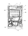
以下、図面を参照して本発明の好適な実施形態について説明する。先ず、図1乃至図3を参照して実施形態に係るパチンコ機の全体構成について説明する。図1は、パチンコ機を示す正面図である。図2は、本体枠及び前面枠を開放した状態のパチンコ機を示す斜視図である。図3は、パチンコ機1の裏面構成を示す背面図である。   Hereinafter, preferred embodiments of the present invention will be described with reference to the drawings. First, the overall configuration of the pachinko machine according to the embodiment will be described with reference to FIGS. 1 to 3. FIG. 1 is a front view showing a pachinko machine. FIG. 2 is a perspective view showing the pachinko machine with the main body frame and the front frame opened. FIG. 3 is a rear view showing the rear surface configuration of the pachinko machine 1.

図1及び図2に示すように、遊技機としてのパチンコ機1は、外枠2、本体枠3、遊技盤4、前面枠5等を備えて構成されている。外枠2は、上下左右の枠材によって縦長四角形の枠状に形成され、外枠2の前側下部には、本体枠3の下面を受ける下受板6を有している。外枠2の前面一側には、ヒンジ機構7によって本体枠3が前方に開閉可能に装着されている。また、本体枠3は、前枠体8、遊技盤装着枠9、及び機構装着枠10を合成樹脂材によって一体成形することで構成されている。本体枠3の前側に形成された前枠体8は、外枠2前側の下受板6を除く外郭形状に対応する大きさの矩形枠状に形成されている。なお、本実施形態では、パチンコ機1の正面を視認する視線方向を前側(前面側)とし、これとは反対側(例えば、前枠体8に対する本体枠3側)を後側(背面側)とする。   As shown in FIGS. 1 and 2, a pachinko machine 1 as a gaming machine includes an outer frame 2, a main body frame 3, a game board 4, a front frame 5, and the like. The outer frame 2 is formed in a vertically rectangular frame shape by upper, lower, left and right frame members, and has a lower plate 6 that receives the lower surface of the main body frame 3 at the lower front side of the outer frame 2. A main body frame 3 is attached to the front side of the outer frame 2 by a hinge mechanism 7 so as to be opened and closed forward. The main body frame 3 is formed by integrally molding the front frame body 8, the game board mounting frame 9, and the mechanism mounting frame 10 with a synthetic resin material. The front frame 8 formed on the front side of the main body frame 3 is formed in a rectangular frame shape having a size corresponding to the outer shape excluding the support plate 6 on the front side of the outer frame 2. In the present embodiment, the line-of-sight direction for viewing the front of the pachinko machine 1 is the front side (front side), and the opposite side (for example, the main body frame 3 side with respect to the front frame body 8) is the rear side (back side). And

また、本体枠3は、合成樹脂材によって一体に形成されると共に、前面側に遊技盤装着枠9が背面側に機構装着枠10がそれぞれ形成されている。これによって、合成樹脂製の本体枠3は、従来の前枠(内枠、前面枠等と呼ばれることがある)と、機構板(裏機構板、裏セット板等と呼ばれることがある)との機能を兼ね備えている。   The main body frame 3 is integrally formed of a synthetic resin material, and a game board mounting frame 9 is formed on the front side, and a mechanism mounting frame 10 is formed on the back side. As a result, the synthetic resin main body frame 3 has a conventional front frame (sometimes called an inner frame, a front frame, etc.) and a mechanism plate (sometimes called a back mechanism plate, a back set plate, etc.). It has a function.

前枠体8の後部に一体的に形成された遊技盤装着枠9には、遊技盤4が前方から着脱交換可能に装着されるようになっている。また、遊技盤装着枠9の左側部には、係合突部33が上下に2つ形成され、遊技盤装着枠9の右側部には、係合凹部(図示しない)が上下に2つ形成されている。また、遊技盤4の盤面(前面)の左側部には係合突部33と対応する係止穴34が上下に2つ形成され、遊技盤4の盤面の右側部には係合凹部と対応する係合フック35が上下に2つ形成されている。係合フック35は、遊技盤4と遊技盤装着枠9とを係脱可能に係止する。   A game board 4 is attached to the game board mounting frame 9 integrally formed at the rear part of the front frame body 8 so as to be detachable and replaceable from the front. In addition, two engaging protrusions 33 are formed on the left side of the game board mounting frame 9 and two engagement recesses (not shown) are formed on the right side of the game board mounting frame 9. Has been. In addition, two locking holes 34 corresponding to the engaging protrusions 33 are formed on the left side of the board surface (front surface) of the game board 4 and corresponding to the engaging recesses on the right side of the board surface of the gaming board 4. Two engaging hooks 35 are formed vertically. The engaging hook 35 detachably engages the game board 4 and the game board mounting frame 9.

また、遊技盤4の盤面には、外レールと内レールとを備えた案内レール11が設けられ、該案内レール11によって区画された領域が発射された遊技球を落下させる遊技領域12として形成されている。遊技盤装着枠9よりも下方に位置する前枠体8の前側下部の一側寄りには、下部スピーカ14が装着されている。また、前枠体8前面の下部領域内の上側部分には、遊技盤4の発射通路に向けて遊技球を導く発射レール15が傾斜状に装着されている。一方、前枠体8前面の下部領域内の下側部分には、下前面部材16が装着されている。下前面部材16前面のほぼ中央には、下皿17が設けられ、片側寄りには操作ハンドル18が設けられている。   In addition, a guide rail 11 having an outer rail and an inner rail is provided on the board surface of the game board 4, and an area defined by the guide rail 11 is formed as a game area 12 for dropping the launched game ball. ing. A lower speaker 14 is attached to one side of the front lower portion of the front frame body 8 positioned below the game board mounting frame 9. A launch rail 15 that guides a game ball toward the launch path of the game board 4 is attached to the upper portion in the lower region of the front surface of the front frame 8 in an inclined manner. On the other hand, a lower front member 16 is attached to a lower portion in the lower area of the front surface of the front frame body 8. A lower pan 17 is provided substantially at the center of the front surface of the lower front member 16, and an operation handle 18 is provided closer to one side.

また、本体枠3(前枠体8)のヒンジ機構7が設けられる側とは反対側となる開放側の後面には、外枠2に対して本体枠3を施錠する機能と、本体枠3に対して前面枠5を施錠する機能とを兼ね備えた施錠装置19が装着されている。施錠装置19は、外枠2に設けられた閉止具20に係脱可能に係合して本体枠3を閉鎖状態に施錠する上下複数の本体枠施錠フック21と、前面枠5の開放側の後面に設けられた閉止具22に係脱可能に係合して前面枠5を閉鎖状態に施錠する上下複数の扉施錠フック23とを備えている。   Further, a function of locking the main body frame 3 with respect to the outer frame 2 on the rear surface of the main body frame 3 (front frame body 8) opposite to the side where the hinge mechanism 7 is provided, and the main body frame 3 On the other hand, a locking device 19 having the function of locking the front frame 5 is mounted. The locking device 19 includes a plurality of upper and lower body frame locking hooks 21 that are detachably engaged with a closing tool 20 provided on the outer frame 2 to lock the main body frame 3 in a closed state, and an open side of the front frame 5. There are provided a plurality of upper and lower door locking hooks 23 that are detachably engaged with a closing tool 22 provided on the rear surface and lock the front frame 5 in a closed state.

しかして、シリンダー錠24の鍵穴に鍵が挿入されて一方向に回動操作されることで、本体枠施錠フック21と外枠2の閉止具20との係合が解除されて本体枠3が解錠され、これとは逆方向に鍵が回動操作されることで、扉施錠フック23と前面枠5の閉止具22との係合が解除されて前面枠5が解錠されるようになっている。シリンダー錠24の前端部は、パチンコ機1の前方から鍵を挿入して解錠操作が行えるように、前枠体8及び下前面部材16を貫通して下前面部材16の前面に露出して配置されている。   Thus, when the key is inserted into the key hole of the cylinder lock 24 and rotated in one direction, the engagement between the main body frame locking hook 21 and the closing tool 20 of the outer frame 2 is released, and the main body frame 3 is moved. When unlocked and the key is rotated in the opposite direction, the engagement between the door locking hook 23 and the closing tool 22 of the front frame 5 is released, and the front frame 5 is unlocked. It has become. The front end of the cylinder lock 24 is exposed to the front surface of the lower front member 16 through the front frame 8 and the lower front member 16 so that the unlocking operation can be performed by inserting a key from the front of the pachinko machine 1. Has been placed.

なお、本実施形態では、時計回り方向に鍵を回動操作することで外枠2に対して本体枠3が解錠され、反時計回り方向に鍵を解錠操作することで本体枠3に対して前面枠5が解錠される。このように、回動操作の方向を異ならせるだけで、本体枠3又は前面枠5のいずれかを解錠させることができる。また、施錠装置19は、本体枠3を閉塞状態に施錠したときに、鍵以外の外部操作によって本体枠施錠フック21と外枠2の閉止具20との係合が解除されないように本体枠施錠フック21をロックするロック機構をさらに備えている。しかして、本体枠3を閉塞状態に施錠したときには、ロック機構により本体枠施錠フック21がロックされる。また、本体枠施錠フック21よりも外枠2と本体枠3(前面枠8)との間隙に近い側(図2において右側方)にリブが突設形成され、当該リブにより本体枠施錠フック21が外枠2と本体枠3(前面枠8)との間隙から針金等を差し込んで直接本体枠施錠フック21を操作しようとしてもリブに当接する。従って、外枠2と本体枠3(前面枠3)との間隙から針金等により本体枠3を不正に解錠する不正行為を防止することができる。   In this embodiment, the main body frame 3 is unlocked with respect to the outer frame 2 by rotating the key in the clockwise direction, and the main body frame 3 is unlocked by operating the key in the counterclockwise direction. On the other hand, the front frame 5 is unlocked. Thus, either the main body frame 3 or the front frame 5 can be unlocked only by changing the direction of the rotation operation. The locking device 19 also locks the main body frame 3 so that the engagement between the main body frame locking hook 21 and the closing tool 20 of the outer frame 2 is not released by an external operation other than the key when the main body frame 3 is locked in the closed state. A lock mechanism for locking the hook 21 is further provided. Thus, when the main body frame 3 is locked in the closed state, the main body frame locking hook 21 is locked by the lock mechanism. Further, a rib is formed to project from the side closer to the gap between the outer frame 2 and the main body frame 3 (front frame 8) than the main body frame locking hook 21 (right side in FIG. 2), and the main body frame locking hook 21 is formed by the rib. However, even if an attempt is made to directly operate the main body frame locking hook 21 by inserting a wire or the like from the gap between the outer frame 2 and the main body frame 3 (front frame 8), the rib contacts the rib. Accordingly, it is possible to prevent an illegal act of illegally unlocking the main body frame 3 with a wire or the like from the gap between the outer frame 2 and the main body frame 3 (front surface frame 3).

本体枠3前面の一側には、ヒンジ機構25によって前面枠5が前方に開閉可能に装着されている。前面枠5は、扉本体フレーム26、上皿28を備えて構成されている。扉本体フレーム26は、プレス加工された金属製フレーム部材によって構成され、前枠体8の上端から下前面部材16の上縁に亘る部分を覆う大きさに形成されている。扉本体フレーム26のほぼ中央には、遊技領域12を前方から透視可能なほぼ円形状の開口窓30が形成されている。また、扉本体フレーム26の後側には、開口窓30よりも大きい矩形枠状をなす窓枠31が設けられ、該窓枠31には、透明板32が装着されている。   A front frame 5 is attached to one side of the front surface of the main body frame 3 by a hinge mechanism 25 so as to be opened and closed forward. The front frame 5 includes a door body frame 26 and an upper plate 28. The door main body frame 26 is formed of a pressed metal frame member, and is formed to have a size that covers a portion extending from the upper end of the front frame body 8 to the upper edge of the lower front member 16. A substantially circular opening window 30 through which the game area 12 can be seen through from the front is formed in the approximate center of the door body frame 26. Further, a window frame 31 having a rectangular frame shape larger than the opening window 30 is provided on the rear side of the door body frame 26, and a transparent plate 32 is attached to the window frame 31.

なお、本実施形態では、遊技盤4の下方にシリンダー錠24を配置し、遊技盤4の右方に配置された施錠装置19を薄型化することで、遊技盤4に形成された遊技領域12の面積を従来よりも拡大することができ、遊技者の視認に対する興趣を高めることができる。また、遊技領域12の拡大に合わせて前面枠8の開口窓30も拡大され、該前面枠8の剛性が低下することとなるが、上皿28を一体的に構成する前面枠8とすることで、前面枠8の剛性の低下を抑制している。   In the present embodiment, the cylinder lock 24 is disposed below the game board 4, and the locking device 19 disposed on the right side of the game board 4 is thinned, so that the game area 12 formed on the game board 4. The area of the player can be expanded more than before, and the interest for the player's visual recognition can be enhanced. In addition, the opening window 30 of the front frame 8 is enlarged in accordance with the enlargement of the game area 12, and the rigidity of the front frame 8 is reduced. However, the front frame 8 that integrally forms the upper plate 28 is used. Thus, a decrease in rigidity of the front frame 8 is suppressed.

扉本体フレーム26の前側には、開口窓30の周囲において、下部に上皿28が前面枠8と一体的に設けられ、左右両側部に枠ランプ27が、上部に上部スピーカ29が装着されている。なお、枠ランプ27は、各種遊技内容に応じて点灯・消灯制御され、上部スピーカ29及び下部スピーカ14は、各種遊技内容に応じて複数種類の音出力態様の音出力制御が実行される。このように、各種遊技内容に応じて枠ランプ27の点灯・消灯制御、上部スピーカ29及び下部スピーカ14の音出力制御、を実行することにより演出効果を高め、遊技者の興趣を向上するようになっている。また、上部スピーカ29及び下部スピーカ14では、不正行為が実行されたことを報知する警告音、遊技に関するエラー状態が発生したことを報知する情報音、等の出力も行われる。   On the front side of the door body frame 26, an upper plate 28 is provided integrally with the front frame 8 at the lower part around the opening window 30, frame lamps 27 are mounted on the left and right sides, and an upper speaker 29 is mounted on the upper part. Yes. The frame lamp 27 is controlled to be turned on / off according to various game contents, and the upper speaker 29 and the lower speaker 14 are subjected to sound output control of a plurality of types of sound output modes according to various game contents. As described above, by performing the lighting / extinguishing control of the frame lamp 27 and the sound output control of the upper speaker 29 and the lower speaker 14 according to various game contents, it is possible to enhance the production effect and improve the interest of the player. It has become. The upper speaker 29 and the lower speaker 14 also output a warning sound for notifying that an illegal act has been executed, an information sound for notifying that an error state relating to a game has occurred, and the like.

次に、本体枠3の裏面構成について説明すると、図3に示すように、本体枠3の裏面には、遊技球を払い出す払出装置100(賞球払出手段)と、遊技島に設置される球揚送装置から供給される遊技球を貯留する球タンク101と、該球タンク101と払出装置100とを接続して球タンク100に貯留される遊技球を流下せしめるタンクレール102と、が配置されている。なお、タンクレール102によって球タンク101と接続される払出装置100は、ユニット状に形成され、タンクレール102からの遊技球を受け入れて遊技球の払い出しを指示する信号に基づいて所定個数(本実施形態では、13個)の遊技球を払い出す。   Next, the rear surface configuration of the main body frame 3 will be described. As shown in FIG. 3, on the rear surface of the main body frame 3, a payout device 100 (award ball payout means) for paying out game balls and a game island are installed. A ball tank 101 that stores game balls supplied from the ball lifting device, and a tank rail 102 that connects the ball tank 101 and the payout device 100 to flow down the game balls stored in the ball tank 100 are arranged. Has been. Note that the payout device 100 connected to the ball tank 101 by the tank rail 102 is formed in a unit shape, and receives a game ball from the tank rail 102 and receives a predetermined number (this embodiment) based on a signal instructing payout of the game ball. In the form, 13) game balls are paid out.

また、タンクレール102の下方には、基板等が内蔵される基板保護カバー103が設けられている。基板保護カバー103は、タンクレール102から落下した球によってこれら基板類が損傷するのを防止すると共に、各基板への不正行為を防止する役割を担っている。また、基板保護カバー103は、パチンコ機1の背面側に張り出しており、その下方に主基板110が配置されている。また、主基板110の遊技盤4背面側には、サブ統合基板120(図5に符号のみ記載)が配置されている。しかして、主基板110及びサブ統合基板120の上方がパチンコ機1の背面側に張り出した基板保護カバー103によって覆われ、タンクレール102から落下した球によって主基板110及びサブ統合基板120が損傷するのを防止している。   A substrate protective cover 103 in which a substrate and the like are incorporated is provided below the tank rail 102. The substrate protective cover 103 plays a role of preventing these substrates from being damaged by the spheres dropped from the tank rail 102 and preventing illegal acts on the respective substrates. Further, the substrate protection cover 103 projects to the back side of the pachinko machine 1, and the main substrate 110 is disposed below the substrate protection cover 103. Further, a sub-integrated board 120 (only the reference numeral is shown in FIG. 5) is arranged on the back side of the main board 110 on the game board 4. Accordingly, the upper side of the main board 110 and the sub-integrated board 120 is covered with the board protection cover 103 protruding to the back side of the pachinko machine 1, and the main board 110 and the sub-integrated board 120 are damaged by the balls dropped from the tank rail 102. Is preventing.

また、本体枠3の裏面下側一側には、発射装置104が取り付けられている。発射装置104は、発射レール15に送られた球を発射する発射ハンマーや該発射ハンマーに往復回動動作を付与する発射モータ等を集約して設けることにより構成され、操作ハンドル18と関連付けられている。また、発射装置104の右側方には、払出制御基板115が設けられている。払出制御基板115は、主基板110からの遊技球の払い出しを指示する信号(球払出信号)を受信したことに基づいて払出装置100を駆動制御する。なお、主基板110は、後述する入賞口スイッチ36,42,63,83,95,96による遊技球の検出信号を受信することで、払出制御基板115に球払出信号を送信する。   A launching device 104 is attached to the lower side of the back surface of the main body frame 3. The launching device 104 is configured by integrating a launching hammer that launches a sphere sent to the launching rail 15 and a launching motor that imparts a reciprocating rotation to the launching hammer, and is associated with the operation handle 18. Yes. Further, a payout control board 115 is provided on the right side of the launching device 104. The payout control board 115 drives and controls the payout device 100 based on the reception of a signal (ball payout signal) instructing payout of game balls from the main board 110. The main board 110 transmits a ball payout signal to the payout control board 115 by receiving a detection signal of a game ball by a winning opening switch 36, 42, 63, 83, 95, 96, which will be described later.

次に、遊技盤4に区画形成された遊技領域12内に設けられる各種構成部材について図4を参照して説明する。図4は、遊技盤4を示す正面図である。   Next, various components provided in the game area 12 partitioned on the game board 4 will be described with reference to FIG. FIG. 4 is a front view showing the game board 4.

図4に示すように、遊技領域12のほぼ中央には、入賞振分装置40が配置されている。入賞振分装置40は、上端位置に配置された入賞口41(球入口)と、該入賞口41に入賞した遊技球を検出する入賞口スイッチ42(図9参照、球検出手段)と、入賞口41に入賞した遊技球を下方に誘導する螺旋形状の誘導通路43と、該誘導通路43の球排出口43aから落下排出された遊技球を視認可能に転動するクルーン転動板44(旋回転動板)と、該クルーン転動板44の球落下口44a(図6参照)から落下排出された遊技球を受け入れる下部空間45と、を備えている。   As shown in FIG. 4, a prize distribution device 40 is arranged in the approximate center of the game area 12. The winning distribution device 40 includes a winning opening 41 (ball entrance) arranged at the upper end position, a winning opening switch 42 (see FIG. 9, ball detecting means) for detecting a game ball that has won the winning opening 41, and winning. A spiral-shaped guide passage 43 that guides the game ball won in the mouth 41 downward, and a Clune rolling plate 44 that rolls the game ball dropped and discharged from the ball discharge port 43a of the guide passage 43 so as to be visible. And a lower space 45 for receiving the game balls dropped and discharged from the ball drop port 44a (see FIG. 6) of the Kroon rolling plate 44.

下部空間45には、モータ46(図8参照)の駆動に基づいて常時時計方向に回転する球受回転体47(球振分手段)が設けられている。球受回転体47の外周部分には、遊技球1個を受け入れる大きさに穿設された切欠部が全周に沿って3つ設けられ、そのうちの1つの切欠部が当選切欠部48を構成し、残り2つの切欠部が落選切欠部49を構成している。そして、当選切欠部48に入った遊技球は、球受回転体47の回転に伴って遊技盤4裏面の特別通路部50(図11参照)に送り込まれ、後述する当選遊技状態を発生させる。一方、落選切欠部49に入った遊技球は、球受回転体47の回転に伴って遊技盤4裏面の排出通路部51(図11参照)に送り込まれて回収される。なお、入賞振分装置40の詳細な構成については後述する。   The lower space 45 is provided with a ball receiving rotating body 47 (ball distributing means) that always rotates in the clockwise direction based on driving of a motor 46 (see FIG. 8). The outer peripheral portion of the ball receiving rotating body 47 is provided with three notches that are sized to receive one game ball along the entire circumference, and one of these notches constitutes the winning notch 48. The remaining two cutouts constitute a lost cutout 49. Then, the game ball that has entered the winning cutout portion 48 is sent to a special passage portion 50 (see FIG. 11) on the back of the game board 4 as the ball receiving rotator 47 rotates, thereby generating a winning gaming state to be described later. On the other hand, the game ball that has entered the unsuccessful notch 49 is sent to the discharge passage 51 (see FIG. 11) on the back of the game board 4 as the ball receiving rotor 47 rotates and is collected. The detailed configuration of the winning distribution device 40 will be described later.

入賞振分装置40の下方には、上部可変入賞球装置60(可変入賞球装置)が配置され、該上部可変入賞球装置60の下方には、下部可変入賞球装置80(可変入賞球装置)が配置されている。   An upper variable winning ball device 60 (variable winning ball device) is disposed below the winning distribution device 40, and a lower variable winning ball device 80 (variable winning ball device) is disposed below the upper variable winning ball device 60. Is arranged.

上部可変入賞球装置60は、当該上部可変入賞球装置60を遊技盤4の表面(遊技領域12)に取り付けるための取付基板61を有している。取付基板61の上側部分には、遊技球1個分の大きさに形成された第1,第4の可変入賞口61a,61dが左右一対に穿設され、取付基板61の下側部分には、遊技球1個分の大きさに形成された第2,第3の可変入賞口61b,61cが左右一対に穿設されている。即ち、第1〜第4の可変入賞口61a〜61d(入賞口)が取付基板61の左上、左下、右下、右上の計4箇所に設けられている。   The upper variable winning ball device 60 has an attachment board 61 for mounting the upper variable winning ball device 60 on the surface of the game board 4 (game area 12). The upper portion of the mounting board 61 is formed with a pair of left and right variable winning holes 61a, 61d formed in the size of one game ball. A pair of left and right variable winning holes 61b and 61c formed in the size of one game ball are formed. That is, the first to fourth variable winning holes 61 a to 61 d (winning holes) are provided at a total of four locations on the mounting substrate 61, that is, upper left, lower left, lower right, and upper right.

また、第1,第4の可変入賞口61a,61dが穿設された上側部分と、第2,第3の可変入賞口61b,61cが穿設された下側部分との間に位置する取付基板61の左右両端部には、それぞれ取付基板61の中央に向って下り傾斜した誘導突起61eが突設されている。左側の誘導突起61eは、第2可変入賞口61bの左上の近傍部分に突設されることで、当該誘導突起61e上に流下した遊技球を第2可変入賞口61b側に誘導する。右側の誘導突起61eは、第3可変入賞口61cの右上の近傍部分に突設されることで、当該誘導突起61e上に流下した遊技球を第3可変入賞口61c側に誘導する。   Further, the mounting is located between the upper part where the first and fourth variable winning ports 61a and 61d are formed and the lower part where the second and third variable winning ports 61b and 61c are formed. At both left and right end portions of the substrate 61, guide protrusions 61e that are inclined downward toward the center of the mounting substrate 61 are provided. The left guide protrusion 61e is provided in the vicinity of the upper left portion of the second variable winning opening 61b, thereby guiding the game ball flowing down on the guide protrusion 61e toward the second variable winning opening 61b. The right guide protrusion 61e is provided in the vicinity of the upper right portion of the third variable winning opening 61c, thereby guiding the game ball flowing down on the guide protrusion 61e toward the third variable winning opening 61c.

第1〜第4の可変入賞口61a〜61dには、それぞれ開閉部材62(回動部材)が設けられている。開閉部材62は、遊技盤4の裏面に設けられた開放機構及び閉鎖機構(遊技球の重さを物理的に利用した機構、詳細な構造は後述する)によって傾動位置(可変入賞口61a〜61dを開放する位置)と垂直位置(可変入賞口61a〜61dを閉鎖する位置)との間で移行可能になっている。具体的には、前述した当選切欠部48に入って特別通路部50に送り込まれた遊技球が遊技盤4裏面の開放機構を作動することで、第1〜第4の可変入賞口61a〜61dの全ての開閉部材62が垂直位置から傾動位置に移行し、第1〜第4の可変入賞口61a〜61dが開放するようになっている。即ち、開放機構は、特別通路部50に送り込まれた遊技球の作用によって全ての可変入賞口61a〜61dを開放するようになっている。   The first to fourth variable prize winning openings 61a to 61d are provided with opening / closing members 62 (rotating members), respectively. The opening / closing member 62 is tilted (variable winning openings 61a to 61d) by an opening mechanism and a closing mechanism (a mechanism that physically uses the weight of the game ball, which will be described in detail later) provided on the back surface of the game board 4. And a vertical position (positions at which the variable winning openings 61a to 61d are closed) can be shifted. Specifically, the first to fourth variable winning openings 61a to 61d are obtained by operating the opening mechanism on the back side of the game board 4 by the game ball that has entered the above-described winning cutout portion 48 and fed into the special passage portion 50. All of the open / close members 62 are shifted from the vertical position to the tilted position, and the first to fourth variable prize winning openings 61a to 61d are opened. That is, the opening mechanism is configured to open all the variable prize winning openings 61a to 61d by the action of the game ball sent into the special passage portion 50.

一方、開放状態にある第1〜第4の可変入賞口61a〜61dにおいて、遊技球が入賞するとその遊技球が遊技盤4裏面の閉鎖機構を作動することで、開閉部材62が傾動位置から垂直位置に移行して第1〜第4の可変入賞口61a〜61dを閉鎖するようになっている。但し、閉鎖機構は、各可変入賞口61a〜61d毎に作用し、第1〜第4の可変入賞口61a〜61dのうち遊技球が入賞した可変入賞口(開閉部材62)のみを閉鎖するようになっている。   On the other hand, when the game ball wins in the first to fourth variable winning ports 61a to 61d in the open state, the game ball operates the closing mechanism on the back surface of the game board 4 so that the opening / closing member 62 is perpendicular to the tilt position. It shifts to a position and closes the 1st-4th variable prize winning openings 61a-61d. However, the closing mechanism operates for each of the variable winning ports 61a to 61d, and closes only the variable winning port (opening / closing member 62) where the game ball has won among the first to fourth variable winning ports 61a to 61d. It has become.

また、第1〜第4の可変入賞口61a〜61dの裏面側には、それぞれ入賞した遊技球を個々の方向に誘導する誘導路64〜67(図22(B)参照)が連通して設けられ、各誘導路64〜67には、各可変入賞口61a〜61dに入った遊技球を検出するための入賞口スイッチ63(図22(B)参照)が設けられている。第1可変入賞口61aと連通する誘導路64は、第1可変入賞口61aに入った遊技球を後述する第1入賞球装置91の方向(具体的には、第1チューリップ式入賞口91cの開放機構)に誘導する。第2可変入賞口61bと連通する誘導路65は、第2可変入賞口61bに入った遊技球を後述する第2入賞球装置92の方向(具体的には、第2チューリップ式入賞口92cの開放機構)に誘導する。第3可変入賞口61cと連通する誘導路66は、第3可変入賞口61cに入った遊技球を後述する第3入賞球装置93の方向(具体的には、第3チューリップ式入賞口93cの開放機構)に誘導する。第4可変入賞口61dと連通する誘導路67は、第4可変入賞口61dに入った遊技球を後述する第4入賞球装置94の方向(具体的には、第4チューリップ式入賞口94bの開放機構)に誘導する。   In addition, guide paths 64 to 67 (see FIG. 22B) for guiding the winning game balls in respective directions are provided in communication with the back surfaces of the first to fourth variable winning ports 61a to 61d. Each of the guide paths 64 to 67 is provided with a winning port switch 63 (see FIG. 22B) for detecting a game ball that has entered each of the variable winning ports 61a to 61d. The guide path 64 that communicates with the first variable winning opening 61a is a direction of the first winning ball apparatus 91 (specifically, the first tulip type winning opening 91c), which will be described later. Guide to the opening mechanism. The guide path 65 communicating with the second variable winning opening 61b is a direction of the second winning ball apparatus 92 (specifically, the second tulip type winning opening 92c), which will be described later. Guide to the opening mechanism. The guide path 66 that communicates with the third variable winning opening 61c is a direction of a third winning ball apparatus 93 (specifically, the third tulip winning winning opening 93c) that will be described later. Guide to the opening mechanism. The guide path 67 that communicates with the fourth variable winning opening 61d is a direction of a fourth winning ball apparatus 94 (specifically, the fourth tulip winning winning opening 94b), which will be described later. Guide to the opening mechanism.

次に、上部可変入賞球装置60の下方に配置された下部可変入賞球装置80について説明する。下部可変入賞球装置80は、当該下部可変入賞球装置80を遊技盤4の表面(遊技領域12)に取り付けるための取付基板81を有している。取付基板81の上側部分には、遊技球1個分の大きさに形成された第5,第8の可変入賞口81a,81dが左右一対に穿設され、取付基板81の下側部分には、遊技球1個分の大きさに形成された第6,第7の可変入賞口81b,81cが左右一対に穿設されている。即ち、上部可変入賞球装置60の第1〜第4の可変入賞口61a〜61dと同様に、第5〜第8の可変入賞口81a〜81d(入賞口)が取付基板81の左上、左下、右下、右上の計4箇所に設けられている。   Next, the lower variable winning ball device 80 disposed below the upper variable winning ball device 60 will be described. The lower variable winning ball device 80 has an attachment board 81 for mounting the lower variable winning ball device 80 on the surface of the game board 4 (game area 12). The upper portion of the mounting substrate 81 is provided with a pair of left and right variable winning holes 81a and 81d formed in the size of one game ball. Sixth and seventh variable prize winning openings 81b and 81c formed in the size of one game ball are formed in a pair of left and right. That is, like the first to fourth variable winning holes 61a to 61d of the upper variable winning ball apparatus 60, the fifth to eighth variable winning holes 81a to 81d (winning holes) are the upper left, lower left, It is provided at a total of 4 locations in the lower right and upper right.

また、第5,第8の可変入賞口81a,81dが穿設された上側部分と、第6,第7の可変入賞口81b,81cが穿設された下側部分との間に位置する取付基板81の左右両端部には、上部可変入賞球装置60の誘導突起61eと同様に、取付基板81の中央に向って下り傾斜した誘導突起81eが左右一対に突設されている。左側の誘導突起81eは、第6可変入賞口81bの左上の近傍部分に突設されることで、当該誘導突起81e上に流下した遊技球を第6可変入賞口81b側に誘導する。右側の誘導突起81eは、第7可変入賞口81cの右上の近傍部分に突設されることで、当該誘導突起81e上に流下した遊技球を第7可変入賞口81c側に誘導する。   Further, the mounting is located between the upper part where the fifth and eighth variable winning ports 81a and 81d are drilled and the lower part where the sixth and seventh variable winning ports 81b and 81c are drilled. Similarly to the guide protrusions 61 e of the upper variable winning ball apparatus 60, a pair of left and right guide protrusions 81 e that are inclined downward toward the center of the mounting substrate 81 are provided on the left and right ends of the substrate 81. The left guiding protrusion 81e is provided in the vicinity of the upper left portion of the sixth variable winning opening 81b, thereby guiding the game ball flowing down on the guiding protrusion 81e toward the sixth variable winning opening 81b. The right guiding projection 81e is provided in the vicinity of the upper right portion of the seventh variable winning opening 81c, thereby guiding the game ball flowing down on the guiding protrusion 81e toward the seventh variable winning opening 81c.

第5〜第8の可変入賞口81a〜81dには、それぞれ遊技盤4の裏面に設けられた開放機構及び閉鎖機構(遊技球の重さを物理的に利用した機構、、詳細な構造は後述する)によって傾動位置(可変入賞口81a〜81dを開放する位置)と垂直位置(可変入賞口81a〜81dを閉鎖する位置)との間で移行可能な開閉部材82が設けられている。第5〜第8の可変入賞口81a〜81dの開放機構は、第1〜第4の可変入賞口61a〜61dの開放機構と同様に、当選切欠部48に入って特別通路部50に送り込まれた遊技球の自重によって作動して開閉部材82を垂直位置から傾動位置に移行することで、第5〜第8の可変入賞口81a〜81dを全て開放する。また、第5〜第8の可変入賞口81a〜81dの閉鎖機構についても、第1〜第4の可変入賞口61a〜61dの閉鎖機構と同様に、各可変入賞口81a〜81d毎に設けられて、第5〜第8の可変入賞口81a〜81dのうち遊技球が入賞した可変入賞口(開閉部材82)のみを閉鎖する。   The fifth to eighth variable winning holes 81a to 81d are respectively provided with an opening mechanism and a closing mechanism (a mechanism that physically uses the weight of the game ball, and a detailed structure provided on the back surface of the game board 4). The opening / closing member 82 is provided that can be shifted between a tilt position (a position for opening the variable winning openings 81a to 81d) and a vertical position (a position for closing the variable winning openings 81a to 81d). The opening mechanism of the fifth to eighth variable winning ports 81a to 81d enters the winning cutout portion 48 and is sent to the special passage portion 50, similarly to the opening mechanism of the first to fourth variable winning ports 61a to 61d. The open / close member 82 is moved from the vertical position to the tilted position by being actuated by the weight of the game ball, thereby opening all of the fifth to eighth variable winning ports 81a to 81d. Also, the closing mechanisms of the fifth to eighth variable winning ports 81a to 81d are provided for the variable winning ports 81a to 81d in the same manner as the closing mechanisms of the first to fourth variable winning ports 61a to 61d. Of the fifth to eighth variable winning openings 81a to 81d, only the variable winning opening (opening / closing member 82) where the game ball has been won is closed.

また、第5〜第8の可変入賞口81a〜81dの裏面側には、それぞれ入賞した遊技球を誘導する誘導路84〜87(図22(B)参照)が連通して設けられ、各誘導路84〜87には、各可変入賞口81a〜81dに入った遊技球を検出するための入賞口スイッチ83(図22(B)参照)が設けられている。但し、各可変入賞口81a〜81dと連通する誘導路84〜87は、それぞれ可変入賞口81a〜81dに入った遊技球をそのままパチンコ機1の裏面側に排出する回収通路228〜231(図22(B)参照)に誘導する。なお、上部可変入賞球装置60及び下部可変入賞球装置80の詳細な構成については後述する。   In addition, guide paths 84 to 87 (see FIG. 22B) for guiding the winning game balls are provided in communication with the back surfaces of the fifth to eighth variable winning openings 81a to 81d, respectively. The paths 84 to 87 are provided with a winning opening switch 83 (see FIG. 22B) for detecting a game ball that has entered each of the variable winning openings 81a to 81d. However, the guide paths 84 to 87 communicating with the respective variable winning ports 81a to 81d are collection passages 228 to 231 for discharging the game balls that have entered the variable winning ports 81a to 81d to the back side of the pachinko machine 1 as they are (FIG. 22). (See (B)). The detailed configurations of the upper variable winning ball device 60 and the lower variable winning ball device 80 will be described later.

上部可変入賞球装置60及び下部可変入賞球装置80の左右側方には、第1〜第4の入賞球装置91〜94が設けられている。第1入賞球装置91は、上部可変入賞球装置60の左側方における遊技領域12の側端位置に配置され、第2入賞球装置92は、下部可変入賞球装置80の左側方における近傍位置に配置されている。一方、第3入賞球装置93は、下部可変入賞球装置80の右側方における近傍位置に配置され、第4入賞球装置94は、上部可変入賞球装置60の右側方における遊技領域12の側端位置に配置されている。即ち、第1〜第4の入賞球装置91〜94のうち左右側端に位置する第1,第4の入賞球装置91,94は、第2,第3の入賞球装置92,93に比べて若干高い位置に配置されている。   First to fourth winning ball devices 91 to 94 are provided on the left and right sides of the upper variable winning ball device 60 and the lower variable winning ball device 80. The first winning ball device 91 is disposed at the side end position of the game area 12 on the left side of the upper variable winning ball device 60, and the second winning ball device 92 is located in the vicinity of the left side of the lower variable winning ball device 80. Is arranged. On the other hand, the third winning ball device 93 is arranged in the vicinity of the right side of the lower variable winning ball device 80, and the fourth winning ball device 94 is the side edge of the game area 12 on the right side of the upper variable winning ball device 60. Placed in position. That is, the first and fourth winning ball devices 91 and 94 positioned at the left and right ends of the first to fourth winning ball devices 91 to 94 are compared to the second and third winning ball devices 92 and 93. It is arranged at a slightly higher position.

第1入賞球装置91は、当該第1入賞球装置91を遊技盤4の表面(遊技領域12)に取り付けるための取付基板91aを有している。取付基板91aの上側部分には、入賞口スイッチ95(図5に符号のみ記載)が内臓された第1開放入賞口91bが設けられ、取付基板91aの下側部分には、入賞口スイッチ96(図5に符号のみ記載)が内臓されると共に左右一対の開閉片97を備えた第1チューリップ式入賞口91c(左右一対の開閉片を備えた可変入賞球装置のことであり、以下このような可変入賞球装置をチューリップ式入賞口という)が設けられている。開閉片97は、遊技盤4の裏面に設けられた開放機構及び閉鎖機構(遊技球の重さを物理的に利用した機構)によって傾動位置(第1チューリップ式入賞口91cを開放する位置)と垂直位置(第1チューリップ式入賞口91cを閉鎖する位置)との間で移行可能になっている。   The first winning ball apparatus 91 has an attachment board 91a for attaching the first winning ball apparatus 91 to the surface of the game board 4 (game area 12). The upper portion of the mounting board 91a is provided with a first open winning opening 91b having a winning opening switch 95 (only the reference numeral is shown in FIG. 5), and the lower portion of the mounting board 91a has a winning opening switch 96 ( 5 is a first tulip-type winning opening 91c (a variable winning ball apparatus having a pair of left and right opening / closing pieces), which includes a pair of left and right opening / closing pieces 97. The variable winning ball device is called a tulip type winning opening). The opening / closing piece 97 is tilted by a release mechanism and a closing mechanism (a mechanism that physically uses the weight of the game ball) provided on the back surface of the game board 4 and a position where the first tulip-type winning opening 91c is opened. It is possible to move between the vertical position (position where the first tulip type winning opening 91c is closed).

第1チューリップ式入賞口91cの開放機構は、第1開放入賞口91bに入った遊技球の自重によって作動して開閉片97を垂直位置から傾動位置に移行することで、第1チューリップ式入賞口91cを開放する。一方、開放状態にある第1チューリップ式入賞口91cにおいて、遊技球が入賞するとその遊技球が遊技盤4裏面の閉鎖機構を作動することで、開閉片97が傾動位置から垂直位置に移行して第1チューリップ式入賞口91cを閉鎖する。即ち、第1開放入賞口91bに遊技球が入賞すると、その入賞特典として第1チューリップ式入賞口91cが開放され、第1チューリップ式入賞口91cに遊技球が入賞すると第1チューリップ式入賞口91cが閉鎖される。なお、第1チューリップ式入賞口91cの開放機構には、前述した第1可変入賞口61aに入った遊技球も送り込まれるものであり、当該遊技球による作動においても、同様に第1チューリップ式入賞口91cを開放する。即ち、第1チューリップ式入賞口91cは、第1開放入賞口91bへの入賞及び第1可変入賞口61aへの入賞と連動して開放するようになっている。   The opening mechanism of the first tulip type winning opening 91c is operated by the weight of the game ball that has entered the first opening winning opening 91b, and the opening / closing piece 97 is shifted from the vertical position to the tilting position, thereby the first tulip type winning opening 91c. 91c is opened. On the other hand, when the game ball wins at the first tulip type winning opening 91c in the open state, the game ball operates the closing mechanism on the back surface of the game board 4 so that the opening / closing piece 97 shifts from the tilted position to the vertical position. The first tulip type winning opening 91c is closed. That is, when a game ball wins at the first open winning opening 91b, the first tulip type winning opening 91c is opened as a bonus privilege, and when a gaming ball wins at the first tulip type winning opening 91c, the first tulip type winning opening 91c. Is closed. In addition, the game ball that has entered the first variable prize opening 61a is also sent to the opening mechanism of the first tulip type prize winning port 91c, and the first tulip type prize winning is similarly performed in the operation by the game ball. Open the mouth 91c. That is, the first tulip type winning opening 91c is opened in conjunction with winning in the first opening winning opening 91b and winning in the first variable winning opening 61a.

次に、第2〜第4の入賞球装置92〜94について説明する。但し、第2〜第4の入賞球装置92〜94は、それぞれ第1入賞球装置91と同一の構成部材によって構成される。このため、同一の構成部材における詳細な説明は省略すると共に、同一の構成部材には同一の符号を付して説明を行う。第2入賞球装置92は、当該第2入賞球装置92を遊技盤4の表面(遊技領域12)に取り付けるための取付基板92aを有している。取付基板92aには、第1入賞球装置91の取付基板91aと同様に、入賞口スイッチ95が内臓された第2開放入賞口92bと、入賞口スイッチ96が内臓されると共に左右一対の開閉片97を備えた第2チューリップ式入賞口92cとが設けられている。第2チューリップ式入賞口92cの開放機構は、第1チューリップ式入賞口91cの開放機構と同様に、第2開放入賞口92bに入った遊技球の自重によって作動して開閉片97を垂直位置から傾動位置に移行することで、第2チューリップ式入賞口92cを開放する。   Next, the second to fourth winning ball devices 92 to 94 will be described. However, the second to fourth winning ball devices 92 to 94 are configured by the same constituent members as the first winning ball device 91, respectively. For this reason, while omitting a detailed description of the same constituent members, the same constituent members are denoted by the same reference numerals. The second winning ball apparatus 92 has an attachment board 92a for attaching the second winning ball apparatus 92 to the surface of the game board 4 (game area 12). Similarly to the mounting board 91a of the first winning ball apparatus 91, the mounting board 92a has a second open winning opening 92b with a winning opening switch 95 and a winning opening switch 96 and a pair of left and right opening / closing pieces. And a second tulip-type winning opening 92 c provided with 97. The opening mechanism of the second tulip type winning opening 92c is operated by the weight of the game ball that has entered the second opening winning opening 92b in the same manner as the opening mechanism of the first tulip type winning opening 91c, and the opening and closing piece 97 is moved from the vertical position. By shifting to the tilt position, the second tulip-type winning opening 92c is opened.

一方、第2チューリップ式入賞口92cの閉鎖機構についても、第1チューリップ式入賞口91cの閉鎖機構と同様に、開放状態にある第2チューリップ式入賞口92cにおいて、遊技球が入賞するとその遊技球が遊技盤4裏面の閉鎖機構を作動することで、開閉片97が傾動位置から垂直位置に移行して第2チューリップ式入賞口92cを閉鎖する。即ち、第2開放入賞口92bに遊技球が入賞すると、その入賞特典として第2チューリップ式入賞口92cが開放され、第2チューリップ式入賞口92cに遊技球が入賞すると第2チューリップ式入賞口92cが閉鎖される。なお、第2チューリップ式入賞口91cの開放機構には、前述した第2可変入賞口61bに入った遊技球も送り込まれるものであり、当該遊技球による作動においても、同様に第2チューリップ式入賞口92cを開放する。即ち、第2チューリップ式入賞口92cは、第2開放入賞口92bへの入賞及び第2可変入賞口61bへの入賞と連動して開放するようになっている。   On the other hand, as for the closing mechanism of the second tulip type winning opening 92c, similarly to the closing mechanism of the first tulip type winning opening 91c, when a gaming ball wins in the open second tulip type winning opening 92c, the gaming ball However, by operating the closing mechanism on the back side of the game board 4, the opening / closing piece 97 shifts from the tilting position to the vertical position and closes the second tulip type winning opening 92c. That is, when a game ball wins in the second open winning opening 92b, the second tulip type winning opening 92c is opened as a bonus privilege, and when a gaming ball wins in the second tulip type winning opening 92c, the second tulip type winning opening 92c. Is closed. Note that the game ball that has entered the second variable prize opening 61b is also sent to the opening mechanism of the second tulip type prize opening 91c. Open the mouth 92c. That is, the second tulip-type winning opening 92c is opened in conjunction with winning in the second opening winning opening 92b and winning in the second variable winning opening 61b.

第3入賞球装置93は、当該第3入賞球装置93を遊技盤4の表面(遊技領域12)に取り付けるための取付基板93aを有している。取付基板93aには、第1入賞球装置91の取付基板91aと同様に、入賞口スイッチ95が内臓された第3開放入賞口93bと、入賞口スイッチ96が内臓されると共に左右一対の開閉片97を備えた第3チューリップ式入賞口93cとが設けられている。第3チューリップ式入賞口93cの開放機構は、第1チューリップ式入賞口91cの開放機構と同様に、第3開放入賞口93bに入った遊技球の自重によって作動して開閉片97を垂直位置から傾動位置に移行することで、第3チューリップ式入賞口93cを開放する。   The third winning ball apparatus 93 has an attachment board 93a for attaching the third winning ball apparatus 93 to the surface of the game board 4 (game area 12). Similarly to the mounting board 91a of the first winning ball apparatus 91, the mounting board 93a has a third open winning port 93b in which a winning port switch 95 is incorporated, and a winning port switch 96, and a pair of left and right open / close pieces. And a third tulip-type winning opening 93 c provided with 97. The opening mechanism of the third tulip type winning opening 93c is operated by the own weight of the game ball that has entered the third opening winning opening 93b in the same manner as the opening mechanism of the first tulip type winning opening 91c. By shifting to the tilting position, the third tulip winning prize opening 93c is opened.

一方、第3チューリップ式入賞口93cの閉鎖機構についても、第1チューリップ式入賞口91cの閉鎖機構と同様に、開放状態にある第3チューリップ式入賞口93cにおいて、遊技球が入賞するとその遊技球が遊技盤4裏面の閉鎖機構を作動することで、開閉片97が傾動位置から垂直位置に移行して第3チューリップ式入賞口93cを閉鎖する。即ち、第3開放入賞口93bに遊技球が入賞すると、その入賞特典として第3チューリップ式入賞口93cが開放され、第3チューリップ式入賞口93cに遊技球が入賞すると第3チューリップ式入賞口93cが閉鎖される。なお、第3チューリップ式入賞口93cの開放機構には、前述した第3可変入賞口61cに入った遊技球も送り込まれるものであり、当該遊技球による作動においても、同様に第3チューリップ式入賞口93cを開放する。即ち、第3チューリップ式入賞口93cは、第3開放入賞口93bへの入賞及び第3可変入賞口61cへの入賞と連動して開放するようになっている。   On the other hand, as for the closing mechanism of the third tulip type winning opening 93c, similarly to the closing mechanism of the first tulip type winning opening 91c, when a gaming ball wins in the open third tulip type winning opening 93c, the gaming ball However, by operating the closing mechanism on the back of the game board 4, the opening / closing piece 97 shifts from the tilting position to the vertical position and closes the third tulip type winning opening 93c. That is, when a game ball wins at the third open winning opening 93b, the third tulip type winning opening 93c is opened as a bonus privilege, and when a gaming ball wins at the third tulip type winning opening 93c, the third tulip type winning opening 93c. Is closed. Note that the game ball that has entered the above-described third variable prize opening 61c is also sent to the opening mechanism of the third tulip-type prize opening 93c. The mouth 93c is opened. That is, the third tulip type winning opening 93c is opened in conjunction with winning in the third opening winning opening 93b and winning in the third variable winning opening 61c.

第4入賞球装置93は、当該第4入賞球装置93を遊技盤4の表面(遊技領域12)に取り付けるための取付基板94aを有している。取付基板94aには、第1入賞球装置91の取付基板91aと同様に、入賞口スイッチ95が内臓された第4開放入賞口94bと、入賞口スイッチ96が内臓されると共に左右一対の開閉片97を備えた第4チューリップ式入賞口94cとが設けられている。第4チューリップ式入賞口94cの開放機構は、第1チューリップ式入賞口91cの開放機構と同様に、第4開放入賞口94bに入った遊技球の自重によって作動して開閉片97を垂直位置から傾動位置に移行することで、第4チューリップ式入賞口94cを開放する。   The fourth winning ball apparatus 93 has an attachment board 94a for attaching the fourth winning ball apparatus 93 to the surface of the game board 4 (game area 12). Similarly to the mounting board 91a of the first winning ball apparatus 91, the mounting board 94a has a fourth open winning port 94b with a winning port switch 95 and a winning port switch 96, and a pair of left and right open / close pieces. And a fourth tulip-type winning opening 94 c provided with 97. The opening mechanism of the fourth tulip type winning opening 94c is operated by the weight of the game ball that has entered the fourth opening winning opening 94b in the same manner as the opening mechanism of the first tulip type winning opening 91c, so that the opening and closing piece 97 is moved from the vertical position. By shifting to the tilt position, the fourth tulip-type winning opening 94c is opened.

一方、第4チューリップ式入賞口94cの閉鎖機構についても、第1チューリップ式入賞口91cの閉鎖機構と同様に、開放状態にある第4チューリップ式入賞口94cにおいて、遊技球が入賞するとその遊技球が遊技盤4裏面の閉鎖機構を作動することで、開閉片97が傾動位置から垂直位置に移行して第4チューリップ式入賞口94cを閉鎖する。即ち、第4開放入賞口94bに遊技球が入賞すると、その入賞特典として第4チューリップ式入賞口94cが開放され、第4チューリップ式入賞口94cに遊技球が入賞すると第4チューリップ式入賞口94cが閉鎖される。なお、第4チューリップ式入賞口94cの開放機構には、前述した第4可変入賞口61dに入った遊技球も送り込まれるものであり、当該遊技球による作動においても、同様に第4チューリップ式入賞口94cを開放する。即ち、第4チューリップ式入賞口94cは、第4開放入賞口94bへの入賞及び第4可変入賞口61dへの入賞と連動して開放するようになっている。   On the other hand, as for the closing mechanism of the fourth tulip type winning opening 94c, similarly to the closing mechanism of the first tulip type winning opening 91c, when a gaming ball wins in the open fourth tulip type winning opening 94c, the gaming ball However, by operating the closing mechanism on the back side of the game board 4, the opening / closing piece 97 shifts from the tilting position to the vertical position and closes the fourth tulip type winning opening 94c. That is, when a game ball wins in the fourth open winning opening 94b, the fourth tulip type winning opening 94c is opened as a bonus privilege, and when a game ball wins in the fourth tulip type winning opening 94c, the fourth tulip type winning opening 94c. Will be closed. Note that the game ball that has entered the above-described fourth variable prize-winning port 61d is also sent to the opening mechanism of the fourth tulip-type prize-winning port 94c. Open the mouth 94c. In other words, the fourth tulip type winning opening 94c is opened in conjunction with winning in the fourth opening winning opening 94b and winning in the fourth variable winning opening 61d.

また、遊技領域12には、上記した構成以外にも、一般入賞口37やアウト口38等が設けられている。一般入賞口37は、受け入れた遊技球を遊技盤4裏面に設けられた入賞口スイッチ36(図5に符号のみ記載)に誘導するものであり、入賞振分装置40の上方及び左右側方の計3箇所に配置されている。アウト口38は、遊技領域12の最下端に設けられ、いずれの入賞口にも入賞しなかった遊技球を受け入れてアウト球として回収する。   In addition to the above-described configuration, the game area 12 is provided with a general winning port 37, an out port 38, and the like. The general winning port 37 guides the received game ball to a winning port switch 36 (only the reference numeral is shown in FIG. 5) provided on the back side of the game board 4. There are a total of three locations. The out port 38 is provided at the lowermost end of the game area 12 and accepts a game ball that has not won any winning port and collects it as an out ball.

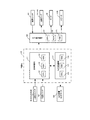
次に、パチンコ機1の裏面側に設けられる主基板110及びサブ統合基板120について図5を参照して説明する。図5は、主基板110及びサブ統合基板120を示すブロック図である。   Next, the main board 110 and the sub-integrated board 120 provided on the back side of the pachinko machine 1 will be described with reference to FIG. FIG. 5 is a block diagram showing the main board 110 and the sub-integrated board 120.

図5に示すように、主基板110は、主制御基板111および払出制御基板115によって構成されている。主制御基板111は、中央演算装置としてのCPU112、読み出し専用メモリとしてのROM113、読み書き可能メモリとしてのRAM114を備えている。CPU112は、ROM113に格納されている遊技制御プログラムを実行することによりパチンコ機1で行われる各種遊技を制御すると共に、払出制御基板115及びサブ統合基板120に送信する信号を作成したりする。また、RAM114には、主制御基板111で実行される種々の処理において生成される各種データや入力信号等の情報が一時的に記憶される。   As shown in FIG. 5, the main board 110 includes a main control board 111 and a payout control board 115. The main control board 111 includes a CPU 112 as a central processing unit, a ROM 113 as a read-only memory, and a RAM 114 as a readable / writable memory. The CPU 112 controls various games performed in the pachinko machine 1 by executing a game control program stored in the ROM 113 and creates a signal to be transmitted to the payout control board 115 and the sub-integrated board 120. The RAM 114 temporarily stores information such as various data and input signals generated in various processes executed by the main control board 111.

主制御基板111には、入賞口スイッチ36,42,63,83,95,96、及び当選スイッチ182からの検出信号が入力される。そして、CPU112は、入力された検出信号に応じた処理を実行する。即ち、入力された検出信号に基づいてサブ統合基板120にコマンド信号を出力すると共に、払出制御基板115に球払出信号を出力する。   The main control board 111 receives detection signals from the winning award port switches 36, 42, 63, 83, 95, 96 and the winning switch 182. Then, the CPU 112 executes processing according to the input detection signal. That is, based on the input detection signal, a command signal is output to the sub-integrated board 120 and a ball payout signal is output to the payout control board 115.

払出制御基板115は、中央演算装置としてのCPU116、読み出し専用メモリとしてのROM117、読み書き可能メモリとしてのRAM118を備えている。そして、払出制御基板115は、主制御基板111から受信した球払出信号を処理し、払出装置100(払出モータ)に駆動信号を出力する。払出装置100は、駆動信号の入力に基づいて遊技球の払い出しを行う。   The payout control board 115 includes a CPU 116 as a central processing unit, a ROM 117 as a read-only memory, and a RAM 118 as a readable / writable memory. The payout control board 115 processes the ball payout signal received from the main control board 111 and outputs a drive signal to the payout device 100 (payout motor). The payout device 100 pays out game balls based on the input of the drive signal.

サブ統合基板120は、CPU121、ROM122、RAM123を備えている。CPU121は、ROM122に格納されている制御プログラムに従ってコマンド信号を処理する。RAM123には、サブ統合基板120で実行される種々の処理において生成される各種データや入出力信号等の情報が一時的に記憶される。サブ統合基板120は、主制御基板111からのコマンド信号に基づいて装飾ランプ157,169、モータ46、スピーカ14,29を制御する。また、サブ統合基板120には、落選スイッチ181からの検出信号が入力される。   The sub integrated board 120 includes a CPU 121, a ROM 122, and a RAM 123. The CPU 121 processes command signals according to a control program stored in the ROM 122. The RAM 123 temporarily stores information such as various data and input / output signals generated in various processes executed by the sub-integrated board 120. The sub integrated board 120 controls the decorative lamps 157 and 169, the motor 46, and the speakers 14 and 29 based on the command signal from the main control board 111. In addition, a detection signal from the selection switch 181 is input to the sub integrated substrate 120.

ここで、遊技内容について簡単に説明する。基本的な遊技内容としては、遊技領域12内に打ち込まれた遊技球がいずれかの入賞口に入賞すると(いずれかの入賞口スイッチ36,42,63,83,95,96によって遊技球が検出されると)、その入賞に基づいて所定数の遊技球が払い出される。本実施形態では、入賞口の種類に関わらず、1個の入賞に対して一律13個の遊技球が賞球として払い出される。また、遊技領域12内に打ち込まれた遊技球が入賞振分装置40の入賞口41に入賞した場合、当該遊技球は、誘導通路43を通ってクルーン転動板44上に排出される。その後、遊技球は、クルーン転動板44上を旋回した後に球落下口44aから下部空間45に送り込まれ、常時回転する球受回転体47の回転動作に応じて当選切欠部48又は落選切欠部49のいずれか一方にはまり込む。落選切欠部49に入った遊技球は、球受回転体47の回転に伴って排出通路部51に送り込まれて回収される。一方、当選切欠部48に入った遊技球は、球受回転体47の回転に伴って特別通路部50に送り込まれ、当選遊技状態を発生させる。   Here, the game content will be briefly described. The basic game content is that when a game ball driven into the game area 12 wins any one of the winning holes (the game ball is detected by any of the winning hole switches 36, 42, 63, 83, 95, 96). A predetermined number of game balls are paid out based on the winning. In the present embodiment, 13 game balls are paid out as prize balls for each prize regardless of the type of prize opening. In addition, when a game ball that has been driven into the game area 12 wins a winning opening 41 of the winning distribution device 40, the gaming ball is discharged onto the cruise rolling plate 44 through the guide passage 43. Thereafter, the game ball is swung on the Kroon rolling plate 44 and then sent to the lower space 45 from the ball drop opening 44a, and the winning cutout portion 48 or the lost cutout portion according to the rotation operation of the ball receiving rotating body 47 that rotates constantly. 49 fits in either one. The game balls that have entered the dropout notch 49 are sent to the discharge passage 51 and collected as the ball receiving rotor 47 rotates. On the other hand, the game ball that has entered the winning cutout portion 48 is sent to the special passage portion 50 as the ball receiving rotator 47 rotates, thereby generating a winning gaming state.

当選遊技状態について説明する。当選遊技状態とは、特別通路部50に送り込まれた遊技球の自重によって開放機構を作動して第1〜第8の可変入賞口61a〜61d,81a〜81dを全て開放した状態である。そして、開放状態にある第1〜第8の可変入賞口61a〜61d,81a〜81dにおいて遊技球が入賞すると、入賞した可変入賞口を順次閉鎖していく。また、このとき、第1〜第4の可変入賞口61a〜61dについては、入賞した可変入賞口と対応するチューリップ式入賞口を順次開放する。具体的には、第1可変入賞口61aに入賞があると、当該入賞した遊技球の自重によって開放機構を作動して第1チューリップ式入賞口91cを開放する。第2可変入賞口61bに入賞があると、当該入賞した遊技球の自重によって開放機構を作動して第2チューリップ式入賞口92cを開放する。第3可変入賞口61cに入賞があると、当該入賞した遊技球の自重によって開放機構を作動して第3チューリップ式入賞口93cを開放する。第4可変入賞口61dに入賞があると、当該入賞した遊技球の自重によって開放機構を作動して第4チューリップ式入賞口94cを開放する。   The winning game state will be described. The winning game state is a state where all of the first to eighth variable winning ports 61a to 61d and 81a to 81d are opened by operating the opening mechanism by the weight of the game ball sent into the special passage portion 50. And when a game ball wins in the 1st-8th variable winning opening 61a-61d and 81a-81d in an open state, the winning variable winning opening will be closed sequentially. At this time, for the first to fourth variable prize winning openings 61a to 61d, the tulip type prize winning openings corresponding to the winning variable prize winning openings are sequentially opened. Specifically, when a winning is made at the first variable winning opening 61a, the opening mechanism is operated by the weight of the winning game ball to open the first tulip winning opening 91c. When there is a winning at the second variable winning opening 61b, the opening mechanism is operated by the weight of the winning game ball to open the second tulip winning hole 92c. When there is a winning at the third variable winning opening 61c, the opening mechanism is operated by the weight of the winning game ball to open the third tulip winning opening 93c. If there is a winning at the fourth variable winning opening 61d, the opening mechanism is operated by the weight of the winning game ball to open the fourth tulip winning opening 94c.

即ち、当選遊技状態が発生した場合には、第1〜第8の可変入賞口61a〜61d,81a〜81d及び第1〜第4のチューリップ式入賞口91c〜94cの計12個の入賞口を開放して、遊技者に入賞機会を多く与えるようになっている。なお、第1〜第4のチューリップ式入賞口91c〜94cは、当選遊技状態が発生していない状態においても、前述したように第1〜第4の開放入賞口91b〜94bへの各入賞と連動して開放するものである。また、当選遊技状態が発生している状態、言い換えれば第1〜第8の可変入賞口61a〜61d,81a〜81dのうちいずれかの可変入賞口が開放している状態で、入賞口41に入賞した遊技球が特別通路部50に送り込まれた場合、開放中の可変入賞口の閉鎖を待つことなく、遊技球が開放機構を作動した時点で、再度全ての可変入賞口61a〜61d,81a〜81dを開放する。   That is, when a winning gaming state occurs, a total of 12 winning mouths including the first to eighth variable winning openings 61a to 61d, 81a to 81d and the first to fourth tulip-type winning openings 91c to 94c are displayed. Open to give players more opportunities to win. Note that the first to fourth tulip-type winning openings 91c to 94c are the winning prizes to the first to fourth open winning openings 91b to 94b as described above, even when the winning gaming state is not generated. It opens in conjunction. Further, in the state where the winning gaming state is generated, in other words, in the state where any one of the first to eighth variable winning ports 61a to 61d, 81a to 81d is open, When the winning game ball is sent to the special passage portion 50, all the variable winning ports 61a to 61d, 81a are again played when the gaming ball operates the opening mechanism without waiting for the opening of the variable winning port being opened. Open ~ 81d.

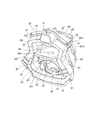
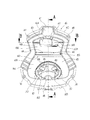
次に、入賞振分装置40の詳細な構成について図6乃至図11を参照して説明する。図6は、入賞振分装置40を示す斜視図である。図7は、入賞振分装置40を示す正面図である。図8は、図7のA−A線断面図である。図9は、図7のB−B線断面図である。図10は、入賞振分装置40の下部空間45に設けられた当選穴178と落選穴177とを示す正面図である。図11は、入賞振分装置40の下部空間45に設けられた特別通路部50と排出通路部51とを示す正面図である。   Next, the detailed configuration of the winning distribution device 40 will be described with reference to FIGS. FIG. 6 is a perspective view showing the prize distribution device 40. FIG. 7 is a front view showing the prize distribution device 40. 8 is a cross-sectional view taken along line AA in FIG. 9 is a cross-sectional view taken along the line BB in FIG. FIG. 10 is a front view showing a winning hole 178 and a winning hole 177 provided in the lower space 45 of the winning distribution device 40. FIG. 11 is a front view showing the special passage portion 50 and the discharge passage portion 51 provided in the lower space 45 of the prize distribution device 40.

図6及び図7に示すように、入賞振分装置40は、当該入賞振分装置40を遊技盤4の表面(遊技領域12)に取り付けるための取付基板140(通路取付部材)を有している。取付基板140の外周部分には、遊技領域12にビス止めするための取付穴141が複数穿設されており、内側部分には、上部開口142と下部開口143とが上下二段に穿設されている。取付基板140の前面側には、入賞口41を形成する前面装飾部材144が一体的に取り付けられる一方、取付基板140の裏面側には、入賞振分装置40を構成する各種構成部材を取り付けるための取付フランジ部145が上部開口142及び下部開口143の外周端に沿って一体的に形成されている。   As shown in FIGS. 6 and 7, the prize distribution device 40 includes an attachment substrate 140 (passage attachment member) for attaching the prize distribution device 40 to the surface of the game board 4 (game area 12). Yes. A plurality of mounting holes 141 for screwing the game area 12 are formed in the outer peripheral portion of the mounting substrate 140, and an upper opening 142 and a lower opening 143 are formed in two upper and lower stages in the inner portion. ing. A front decoration member 144 that forms the winning opening 41 is integrally attached to the front surface side of the mounting substrate 140, while various constituent members constituting the winning distribution device 40 are attached to the rear surface side of the mounting substrate 140. The mounting flange portion 145 is integrally formed along the outer peripheral ends of the upper opening 142 and the lower opening 143.

入賞口41が形成される取付基板140上端の裏面側には、図8に示すように、入賞口41に入った遊技球を誘導するための球通路146が形成され、該球通路146の下流端には、入賞口スイッチ42が取り付けられる。入賞口スイッチ42の下方となる上部開口142内には、誘導通路43を形成する通路部材147が取り付けられる。通路部材147は、図9に示すように、螺旋形状の誘導通路43を形成する通路形成部148と、該通路形成部148の裏面に一体的に形成された板状取付部149と、を備える。通路形成部148には、入賞口スイッチ42を通過した遊技球の落下部分に緩衝誘導突起148aが突設されている。この緩衝誘導突起148aは、落下してくる遊技球の衝撃力を弱めてスムーズに誘導通路43に誘導するためのものである。また、通路形成部148の前端部分には、取付基板140に形成された係合凹部150(係合穴)との係合によって通路部材147を取付基板140に取り付ける係合突起151(遊嵌取付部)が突設されている。なお、係合凹部150の横幅寸法は、係合突起151の横幅寸法に比べて大きく設定されており、係合突起151と係合凹部150との係合は、取付基板140に対する通路部材147の上下方向の位置決めを行うと共に前方(図8に示す左方向)への移動を規制するものであり、横方向(図9に示す左右方向)の位置決めは行わない。   As shown in FIG. 8, a ball passage 146 for guiding a game ball that has entered the winning opening 41 is formed on the back side of the upper end of the mounting board 140 where the winning opening 41 is formed. A prize opening switch 42 is attached to the end. A passage member 147 that forms the guide passage 43 is attached in the upper opening 142 below the winning prize switch 42. As shown in FIG. 9, the passage member 147 includes a passage formation portion 148 that forms a spiral guide passage 43, and a plate-like attachment portion 149 that is integrally formed on the back surface of the passage formation portion 148. . In the passage forming portion 148, a buffer guiding projection 148a is projected from the falling portion of the game ball that has passed through the winning opening switch 42. The buffer guide protrusions 148a are used to weaken the impact force of the falling game ball and guide it smoothly to the guide passage 43. Further, an engagement protrusion 151 (free fitting attachment) that attaches the passage member 147 to the attachment substrate 140 by engaging with an engagement recess 150 (engagement hole) formed in the attachment substrate 140 at the front end portion of the passage formation portion 148 Part). The lateral width of the engagement recess 150 is set to be larger than the lateral width of the engagement protrusion 151, and the engagement between the engagement protrusion 151 and the engagement recess 150 is caused by the passage member 147 with respect to the mounting substrate 140. Positioning in the vertical direction is performed and movement in the forward direction (left direction shown in FIG. 8) is restricted, and positioning in the horizontal direction (left and right direction shown in FIG. 9) is not performed.

板状取付部149は、長方形の板形状をなし、その左右両端部分が取付フランジ部145に穿設された取付切込部152と係合する取付突片部153を構成している。取付突片部153と取付切込部152との係合は、係合突起151と係合凹部150との係合と同様に、取付基板140に対する通路部材147の上下方向の位置決めを行うと共に前方への移動を規制するものであり、横方向の位置決めは行わない。また、板状取付部149の後端部分には、後述する透光装飾板156に穿設された係合穴160と係合する係合突起154(遊嵌取付部)が突設されている。なお、通路形成部148及び板状取付部149を備えた通路部材147は、透明な合成樹脂材料によって一体成形されており、誘導通路43を通過する遊技球は、遊技者側から視認可能となっている。   The plate-like attachment portion 149 has a rectangular plate shape, and both right and left end portions constitute an attachment protrusion piece 153 that engages with an attachment notch portion 152 formed in the attachment flange portion 145. Similar to the engagement between the engagement protrusion 151 and the engagement recess 150, the engagement between the attachment protrusion 153 and the attachment notch 152 positions the passage member 147 in the vertical direction with respect to the attachment substrate 140 and moves forward. The movement in the direction is restricted, and lateral positioning is not performed. Further, at the rear end portion of the plate-like attachment portion 149, an engagement protrusion 154 (free fitting attachment portion) that engages with an engagement hole 160 formed in a translucent decorative plate 156, which will be described later, protrudes. . The passage member 147 having the passage formation portion 148 and the plate-like attachment portion 149 is integrally formed of a transparent synthetic resin material, and the game ball passing through the guide passage 43 can be visually recognized from the player side. ing.

通路部材147の下方となる上部開口142の下端には、クルーン転動板44を形成する転動板部材155が取り付けられる。転動板部材155は、ほぼ正方形の板形状をなし、その上面には円盤形状をなすクルーン転動板44が凹設されている。クルーン転動板44の板面は、中心に向って徐々に下り傾斜した傾斜面に形成され、その中心部分には、下部空間45と連通する球落下口44aが遊技球1個分の大きさで穿設されている。これにより、入賞口41に入った遊技球は、誘導通路43を螺旋状に転動した後、誘導通路43の球排出口43aからクルーン転動板44上に落下し、円盤形状のクルーン転動板44上を旋回し、最終的に球落下口44aを落下して下部空間45に送り込まれる。   A rolling plate member 155 that forms the Clune rolling plate 44 is attached to the lower end of the upper opening 142 that is below the passage member 147. The rolling plate member 155 has a substantially square plate shape, and the upper surface of the rolling plate member 155 has a disk-shaped Kroun rolling plate 44 recessed. The platen surface of the Kroon rolling plate 44 is formed as an inclined surface that is gradually inclined downward toward the center, and a ball dropping port 44a communicating with the lower space 45 is the size of one game ball at the center portion. It is drilled at. As a result, the game ball that has entered the winning opening 41 rolls in the guide passage 43 in a spiral shape, and then falls onto the crurn rolling plate 44 from the ball discharge port 43a of the guide passage 43, thereby rolling the disc-shaped crumb. It turns on the plate 44 and finally falls on the ball drop opening 44 a and is sent into the lower space 45.

通路部材147の裏面側には、透光性を有する合成樹脂板からなる透光装飾板156と、複数の装飾ランプ157(発光手段)が実装されたランプ基板158と、が設けられる。ランプ基板158は、透光装飾板156の裏面に突設された取付ボス159に一体的にビス止めされる。そして、ランプ基板158を一体的に取り付けた透光装飾板156は、該透光装飾板156の左右両端に突設された取付片部156aが取付フランジ部145に形成された取付ボス145aにビス止めされる。これにより、通路部材147と転動板部材155とが取り付けられた上部開口142には、その後端部分を塞ぐようにして透光装飾板156が取り付けられる。なお、透光装飾板156の裏面側に配置された装飾ランプ157は、各種遊技状態に応じたサブ統合基板120の制御に基づいて点灯・点滅が行われ、透光装飾板156を通して上部開口142内を光装飾する。   On the back side of the passage member 147, a translucent decorative plate 156 made of a synthetic resin plate having translucency and a lamp substrate 158 on which a plurality of decorative lamps 157 (light emitting means) are mounted are provided. The lamp substrate 158 is integrally screwed to a mounting boss 159 protruding from the rear surface of the translucent decorative plate 156. The translucent decorative plate 156 to which the lamp substrate 158 is integrally attached is screwed to a mounting boss 145a in which mounting piece portions 156a projecting from the left and right ends of the translucent decorative plate 156 are formed on the mounting flange portion 145. Stopped. Thereby, the translucent decoration board 156 is attached to the upper opening 142 to which the passage member 147 and the rolling plate member 155 are attached so as to close the rear end portion thereof. The decorative lamp 157 arranged on the back side of the translucent decorative board 156 is turned on and blinked based on the control of the sub-integrated board 120 according to various gaming states, and the upper opening 142 is passed through the translucent decorative board 156. The interior is light-decorated.

また、透光装飾板156(遊嵌取付部)には、取付基板140への取付状態において通路部材147の係合突起154と係合する係合穴160が穿設されている。係合穴160の横幅寸法は、係合突起154の横幅寸法に比べて若干大きく設定されている(図9参照)。このため、係合突起154と係合穴160との係合は、透光装飾板156(即ち、透光装飾板156をビス止めした取付基板140)に対する通路部材147の上下方向の位置決めを行うと共に後方(図8に示す右方向)への移動を規制するものであり、横方向(図9に示す左右方向)の位置決めは行わない。但し、係合穴160と係合突起154との横幅寸法差(隙間)は、前述した係合凹部150と係合突起151との横幅寸法差よりも小さく設定されている。これにより、通路部材147は、係合穴160と係合突起154との横幅寸法差(隙間)だけ左右方向に移動し得る遊びを持って取付基板140に取り付けられることになる。   The translucent decorative plate 156 (free fitting attachment portion) is provided with an engagement hole 160 that engages with the engagement protrusion 154 of the passage member 147 when attached to the attachment substrate 140. The width dimension of the engagement hole 160 is set to be slightly larger than the width dimension of the engagement protrusion 154 (see FIG. 9). Therefore, the engagement between the engagement protrusion 154 and the engagement hole 160 positions the passage member 147 in the vertical direction with respect to the translucent decorative plate 156 (that is, the mounting substrate 140 to which the translucent decorative plate 156 is screwed). At the same time, movement in the rear (right direction shown in FIG. 8) is restricted, and positioning in the horizontal direction (left and right direction shown in FIG. 9) is not performed. However, the width difference (gap) between the engagement hole 160 and the engagement protrusion 154 is set to be smaller than the width difference between the engagement recess 150 and the engagement protrusion 151 described above. As a result, the passage member 147 is attached to the attachment substrate 140 with a play that can move in the left-right direction by a difference in lateral width (gap) between the engagement hole 160 and the engagement protrusion 154.

ここで、上記したような遊びを持った通路部材147の取付構造について説明する。誘導通路43を形成する通路部材147は、前述したように通路形成部148の係合突起151が取付基板140の係合凹部150と横方向(図9に示す左右方向)の遊びを持って係合(遊嵌)されると共に、板状取付部149の取付突片部153及び係合突起154が個々に取付基板140の取付切込部152及び透光装飾板156の係合穴160と横方向(図9に示す左右方向)の遊びを持って係合(遊嵌)されることで、取付基板140に取り付けられる。従って、誘導通路43内を遊技球が通過する際、遊技球の流下によって通路部材147が移動する。即ち、取付基板140における通路部材147の取付位置が変わる。このため、遊技球の流下態様に応じて球排出口43aとクルーン転動板44との相対的な位置関係が変わることとなり、球排出口43aからクルーン転動板44上に排出される遊技球の排出位置を変えることができる。その結果、クルーン転動板44上での遊技球の旋回軌跡を多様化することができ、ひいては遊技球の転動における視覚的な興趣を低下することがない。また、この構成によれば、誘導通路43を形成する通路部材147の取り付けに遊びを設けるという簡単な構成で遊技球の旋回軌跡が多様化できる。   Here, the mounting structure of the passage member 147 having the above-described play will be described. In the passage member 147 forming the guide passage 43, the engagement protrusion 151 of the passage formation portion 148 engages with the engagement recess 150 of the mounting substrate 140 in the lateral direction (left-right direction shown in FIG. 9) as described above. The mounting projection piece 153 and the engagement protrusion 154 of the plate-shaped mounting portion 149 are individually connected to the mounting cut portion 152 of the mounting substrate 140 and the engagement hole 160 of the translucent decorative plate 156, respectively. It is attached to the mounting substrate 140 by being engaged (freely fitted) with play in the direction (left and right direction shown in FIG. 9). Accordingly, when the game ball passes through the guide passage 43, the passage member 147 moves due to the flow of the game ball. That is, the attachment position of the passage member 147 on the attachment substrate 140 changes. For this reason, the relative positional relationship between the ball discharge port 43a and the cruise rolling plate 44 changes according to the flow-down mode of the game ball, and the game ball discharged from the ball discharge port 43a onto the cruise rolling plate 44. The discharge position of can be changed. As a result, it is possible to diversify the turning trajectory of the game ball on the Kroon rolling plate 44, and as a result, the visual interest in rolling the game ball is not reduced. Further, according to this configuration, the turning trajectory of the game ball can be diversified with a simple configuration in which play is provided in the attachment of the passage member 147 forming the guide passage 43.

また、上記した遊技球の旋回軌跡を多様化する構成は、その旋回軌跡毎で遊技球が入賞口41に入ってから球落下口44aを落下するまでの時間を異ならせることができる。従って、球振分手段を構成する球受回転体47の当選切欠部48に遊技球が入るタイミングを見計らって遊技者が遊技球の打ち込み操作を行っても、必ずしも遊技球は当選切欠部48に入らなくなる。即ち、遊技球の旋回軌跡を多様化することで、当選切欠部48への遊技球の狙い打ちを阻止することができる。   Moreover, the structure which diversifies the turning locus | trajectory of the above-mentioned game ball can change the time from the game ball | bowl entering the winning opening 41 to dropping the ball | bowl drop opening 44a for every turning locus | trajectory. Therefore, even if the player performs a driving operation of the game ball in anticipation of the timing at which the game ball enters the winning cutout portion 48 of the ball receiving rotator 47 constituting the ball distribution means, the game ball does not necessarily enter the winning cutout portion 48. It will not enter. That is, by diversifying the trajectory of the game ball, it is possible to prevent the game ball from hitting the winning notch 48.

なお、上記したような遊技球を螺旋状に転動してクルーン転動板44上に落下させる誘導通路43は、様々な流下速度で入賞口41に入った遊技球の速度及び流下方向を整えてクルーン転動板44上に送り込む遊技球の整流機能を持つものであり、このような整流機能を持った中で、クルーン転動板44上に排出される遊技球の排出位置に若干の変化を持たせて、前述したような遊技球の旋回軌跡の多様化を招来すると共に、当選切欠部48への遊技球の狙い打ちを阻止するようになっている。   The guide passage 43 that spirally rolls the game ball as described above and drops it onto the Kroon rolling plate 44 adjusts the speed and flow direction of the game ball that has entered the winning opening 41 at various flow speeds. In this way, there is a function of rectifying a game ball to be fed onto the Kroon rolling plate 44. With such a rectifying function, there is a slight change in the discharge position of the game ball discharged on the Kroon rolling plate 44. This causes the diversification of the turning trajectory of the game ball as described above, and prevents the game ball from hitting the winning cutout portion 48.

一方、下部空間45を形成する取付基板140の下部開口143には、該下部開口143内(下部空間45)を遊技者側から視認可能に被覆する透明被覆板161と、該透明被覆板161との間で球落下口44aから送り込まれた遊技球の誘導空間162aを形成する透明仕切板162と、が取り付けられ、該透明仕切板162の裏面側には、球受回転体47を取付基板140に取り付けるための取付部材163と、球受回転体47の上方を覆う被覆部材164と、が設けられる。   On the other hand, in the lower opening 143 of the mounting substrate 140 forming the lower space 45, a transparent covering plate 161 that covers the inside of the lower opening 143 (lower space 45) so as to be visible from the player side, and the transparent covering plate 161, A transparent partition plate 162 that forms a guide space 162a for a game ball sent from the ball drop opening 44a is attached to the back of the transparent partition plate 162. An attachment member 163 for attaching to the sphere and a covering member 164 covering the upper part of the ball receiving rotating body 47 are provided.

透明仕切板162の中央下端部分には、透明仕切板162の裏面側に配置される球受回転体47に誘導空間162a内の遊技球を送り出す送出開口165が穿設されている。送出開口165は、遊技球3個分程度の横幅寸法と遊技球2個程度の縦幅寸法を有した長方形の開口形状をなす。   At the center lower end portion of the transparent partition plate 162, a delivery opening 165 for feeding the game ball in the guide space 162a to the ball receiving rotor 47 disposed on the back side of the transparent partition plate 162 is formed. The delivery opening 165 has a rectangular opening shape having a width dimension of about three game balls and a height dimension of about two game balls.

なお、誘導空間162aの下面は、下部開口143の下辺部分に形成された取付フランジ部145の一部によって構成され、中央及び後側(球受回転体47側)に向って徐々に下り傾斜して形成されている。これにより、誘導空間162a内に送り込まれた遊技球は、自然流下によって送出開口165から球受回転体47側に送り出される。また、誘導空間162a内には、正面から見て円弧形状をなす緩衝突片部166が設けられている。緩衝突片部166は、被覆部材164の前端部分に一体的に形成され、透明仕切板162に穿設された貫通穴を通して誘導空間162a内に配置される。これにより、球落下口44aを落下した遊技球は、一旦、緩衝突片部166で受けられて落下速度を弱めた後に左右いずれかの方向に振り分けられて送出開口165に誘導される。   The lower surface of the guide space 162a is constituted by a part of the mounting flange portion 145 formed in the lower side portion of the lower opening 143, and gradually descends and inclines toward the center and the rear side (the ball receiving rotor 47 side). Is formed. Thereby, the game ball sent into the guidance space 162a is sent out from the delivery opening 165 to the ball receiving rotor 47 side by natural flow. In addition, a buffer protrusion piece 166 having an arc shape when viewed from the front is provided in the guide space 162a. The buffer protrusion 166 is formed integrally with the front end portion of the covering member 164 and is disposed in the guide space 162 a through a through hole formed in the transparent partition plate 162. As a result, the game balls that have fallen through the ball drop opening 44a are once received by the buffer projecting piece 166 to weaken the drop speed, and then distributed in either the left or right direction and guided to the delivery opening 165.

また、透明被覆板161には、正面から見て送出開口165よりも若干外側となる左右二箇所に操作穴167が穿設されている。操作穴167は、誘導空間162a下端での球詰りを解消するための穴である。具体的には、複数の遊技球が連続的に入賞口41に入ることで誘導空間162aの下端で球詰りが生じるような場合、細長い棒状の操作道具を操作穴167から誘導空間162a内に挿入して球詰りを生じた遊技球を押し込むことで、誘導空間162a下端での球詰りを解消する。   In addition, operation holes 167 are formed in the transparent cover plate 161 at two left and right positions slightly outside the delivery opening 165 when viewed from the front. The operation hole 167 is a hole for eliminating ball clogging at the lower end of the guide space 162a. Specifically, when a plurality of game balls continuously enter the winning opening 41 and a ball is clogged at the lower end of the guide space 162a, an elongated rod-like operation tool is inserted into the guide space 162a from the operation hole 167. Then, by pushing in the game ball in which the ball is clogged, the ball clogging at the lower end of the guide space 162a is eliminated.

被覆部材164は、透明な合成樹脂材料によって形成され、前述した緩衝突片部166と、正面から見て球受回転体47以外の領域となる部分で透明仕切板162の裏面と当接する装飾面部168と、を備えている。装飾面部168の裏面には、複数の装飾ランプ169(光照射手段)が実装されたランプ基板170が取り付けられている。これにより、装飾面部168の裏面側に配置された装飾ランプ169は、各種遊技状態に応じたサブ統合基板120の制御に基づいて点灯・点滅が行われ、装飾面部168を通して球受回転体47の外周を光装飾する。   The covering member 164 is formed of a transparent synthetic resin material, and is a decorative surface portion that comes into contact with the back surface of the transparent partition plate 162 in a portion other than the above-described buffer protrusion piece 166 and the ball receiving rotor 47 when viewed from the front. 168. On the back surface of the decorative surface portion 168, a lamp substrate 170 on which a plurality of decorative lamps 169 (light irradiation means) is mounted is attached. As a result, the decoration lamp 169 arranged on the back side of the decoration surface portion 168 is lit and blinked based on the control of the sub-integrated board 120 according to various gaming states, and the ball receiving rotator 47 is passed through the decoration surface portion 168. Light decorate the outer periphery.

取付部材163は、球受回転体47を支承する支承面部171を備えている。支承面部171は、円盤形状をなす球受回転体47よりも若干大きめの凹面形状に形成されており、奥側部分が手前側部分に比べて上方に傾いた傾斜面をなしている。これに伴って、球受回転体47は、奥側部分が手前側部分に比べて上方に傾いて取り付けられ、球受回転体47の外周部分に穿設された3つの切欠部(1つの当選切欠部48と2つの落選切欠部49)が遊技者側から視認し易くなっている。   The attachment member 163 includes a bearing surface portion 171 that supports the ball receiving rotating body 47. The bearing surface portion 171 is formed in a concave shape that is slightly larger than the ball receiving rotator 47 having a disk shape, and has an inclined surface in which the back side portion is inclined upward compared to the front side portion. Along with this, the ball receiving rotator 47 is attached with the rear side portion tilted upward as compared to the front side portion, and three notches (one winning winning hole) drilled in the outer peripheral portion of the ball receiving rotator 47. The notch 48 and the two unsuccessful notches 49) are easily visible from the player side.

図10に示すように、支承面部171の中央部分には、球受回転体47の回転軸172を挿通するための挿通穴173が穿設されている。回転軸172は、その上端部分が球受回転体47裏面の中心に一体的に取り付けられ、挿通穴173に設けられた軸支部173aに回転自在に支持されている。一方、回転軸172の下端部分には、ギヤ174が一体的に取り付けられている。ギヤ174には、取付部材163に回転自在に取り付けられたギヤ175が歯合され、該ギヤ175の中心には、球受回転体47の駆動源となるモータ46の駆動軸46aが一体的に取り付けられている。   As shown in FIG. 10, an insertion hole 173 through which the rotation shaft 172 of the ball receiving rotating body 47 is inserted is formed in the center portion of the support surface portion 171. The rotating shaft 172 has an upper end portion integrally attached to the center of the back surface of the ball receiving rotator 47 and is rotatably supported by a shaft support portion 173 a provided in the insertion hole 173. On the other hand, a gear 174 is integrally attached to the lower end portion of the rotating shaft 172. The gear 174 meshes with a gear 175 rotatably attached to the attachment member 163, and a drive shaft 46 a of a motor 46 serving as a drive source of the ball receiving rotating body 47 is integrally formed at the center of the gear 175. It is attached.

しかして、モータ46の駆動軸46aが回転することで、ギヤ175が一体的に回転し、ギヤ175の回転と連動してギヤ174が回転する。そして、ギヤ174が一体的に取り付けられた回転軸172が回転することにより、球受回転体47が傾斜した支承面部171上で回転する。なお、モータ46の駆動軸46aは、電源投入後常に一方向に回転するようになっており、これに伴って球受回転体47は、稼動期間中常に一方向(遊技者側から見て時計方向)に回転するように構成されている。   Thus, when the drive shaft 46 a of the motor 46 rotates, the gear 175 rotates integrally, and the gear 174 rotates in conjunction with the rotation of the gear 175. Then, when the rotating shaft 172 to which the gear 174 is integrally attached rotates, the ball receiving rotating body 47 rotates on the inclined support surface portion 171. The drive shaft 46a of the motor 46 is always rotated in one direction after the power is turned on. Accordingly, the ball receiving rotating body 47 is always in one direction (clockwise as viewed from the player side) during the operation period. Direction).

円盤形状をなす球受回転体47の外周部分には、前述したように遊技球1個を受け入れる大きさの切欠となる1つの当選切欠部48と2つの落選切欠部49とが穿設されている。これら3つの切欠部48,49は、球受回転体47の外周に沿って一定間隔を置いて設けられている。即ち、球受回転体47の全周(360°)を三等分した120°の等間隔を置いて3つの切欠部48,49が設けられている。そして、入賞口41に入った遊技球が誘導空間162a内に送り込まれた状態で、いずれかの切欠部48,49が誘導空間162aの下端中央位置に回転すると、当該切欠部に誘導空間162a内の遊技球が入り込む。なお、当選切欠部48の近傍となる球受回転体47の上面部分には、当該切欠部が他の2つの切欠部(落選切欠部49)とは異なることを遊技者に認識させる認識シール(図示しない、例えば「V」の文字が付されたシール(当落判別部))を貼付するための凹部176が形成されている。   As described above, one winning cutout portion 48 and two defeating cutout portions 49 are formed in the outer peripheral portion of the ball receiving and rotating body 47 having a disk shape. Yes. These three notches 48 and 49 are provided at regular intervals along the outer periphery of the ball receiving rotating body 47. That is, the three notches 48 and 49 are provided at equal intervals of 120 ° obtained by dividing the entire circumference (360 °) of the ball receiving and rotating body 47 into three equal parts. Then, when any of the notches 48 and 49 is rotated to the center position of the lower end of the guide space 162a in a state where the game ball that has entered the winning opening 41 is sent into the guide space 162a, the notch is inserted into the guide space 162a. Of game balls enter. In addition, a recognition sticker that allows the player to recognize that the notch is different from the other two notches (decision notch 49) on the upper surface portion of the ball receiving rotor 47 in the vicinity of the winning notch 48. A concave portion 176 is formed for attaching a seal (a winning determination portion) with a letter “V” (not shown), for example.

当選切欠部48は、その切込寸法(球受回転体47の外周端部から中心方向への切欠寸法)がほぼ遊技球の直径と同一に設定されている。一方、落選切欠部49の切込寸法は、遊技球の直径よりも若干大きめに設定されている。このため、落選切欠部49に入った遊技球は、傾斜した球受回転体47の回転に伴って(落選切欠部49が上方に移動することに伴って)徐々に球受回転体47の中心方向に移動するようになっている。これに対して、当選切欠部48に入った遊技球は、当選切欠部48がいずれの回転位置に移動しても当選切欠部48内で移動することはなく、一定の位置に保持される。   The winning cutout 48 has a cutout dimension (cutout dimension from the outer peripheral end of the ball receiving rotator 47 toward the center) substantially the same as the diameter of the game ball. On the other hand, the notch size of the dropout notch 49 is set slightly larger than the diameter of the game ball. For this reason, the game ball that has entered the unsuccessful notch 49 is gradually centered on the ball receiving rotator 47 with the rotation of the inclined ball rotator 47 (as the unsuccessful notch 49 moves upward). It is designed to move in the direction. On the other hand, the game ball that has entered the winning cutout portion 48 does not move within the winning cutout portion 48 regardless of the rotation position of the winning cutout portion 48 and is held at a fixed position.

また、支承面部171の左上側部分には、落選穴177が遊技球1個分の大きさに穿設されており、支承面部171の右上側部分には、当選穴178が遊技球1個分の大きさに穿設されている。落選穴177は、挿通穴173に挿通される回転軸172からの距離、即ち球受回転体47の中心からの距離が当選穴178に比べて短い位置に穿設されている。具体的に、落選穴177は、球受回転体47の回転(落選切欠部49の上方移動)に伴って落選切欠部49内で移動した遊技球の位置と対応した箇所に穿設されている。一方、当選穴178は、当選切欠部48内に保持された遊技球の位置と対応した箇所に穿設されている。   In addition, a winning hole 177 is formed in the upper left portion of the bearing surface portion 171 so as to have a size corresponding to one game ball, and a winning hole 178 is provided in the upper right portion of the bearing surface portion 171 for one game ball. It is drilled in the size of. The drop hole 177 is formed at a position where the distance from the rotation shaft 172 inserted into the insertion hole 173, that is, the distance from the center of the ball receiving rotating body 47 is shorter than the winning hole 178. Specifically, the winning hole 177 is formed at a position corresponding to the position of the game ball moved in the winning notch 49 with the rotation of the ball receiving rotator 47 (upward movement of the dropping notch 49). . On the other hand, the winning hole 178 is formed at a position corresponding to the position of the game ball held in the winning notch 48.

しかして、落選切欠部49に入った遊技球は、球受回転体47の回転に伴って徐々に球受回転体47の中心方向に移動し、落選切欠部49が落選穴177の位置まで回転したときに落選穴177に入り込む。一方、当選切欠部48に入った遊技球は、当選切欠部48内で保持されているため(球受回転体47の中心方向に移動しないため)、当選切欠部48が落選穴177の位置まで回転しても落選穴177に入り込むことがない。その後、落選穴177を通過した遊技球は、当選切欠部48が当選穴178の位置まで回転したときに当選穴178に入り込む。   Thus, the game ball that has entered the lost selection notch 49 gradually moves toward the center of the ball receiving rotator 47 as the ball receiving rotator 47 rotates, and the lost selection notch 49 rotates to the position of the lost selection hole 177. When you do, you enter the lost hole 177. On the other hand, since the game ball that has entered the winning cutout portion 48 is held in the winning cutout portion 48 (because it does not move toward the center of the ball receiving rotation body 47), the winning cutout portion 48 reaches the position of the dropout hole 177. Even if it rotates, it will not enter the lost hole 177. Thereafter, the game ball that has passed through the winning hole 177 enters the winning hole 178 when the winning notch 48 rotates to the position of the winning hole 178.

なお、落選穴177の近傍となる支承面部171の上面部分には、落選切欠部49内の遊技球をスムーズに落選穴177に送り込むための誘導溝179が形成されており、当選穴178の近傍となる支承面部171の上面部分には、当選切欠部48内の遊技球をスムーズに当選穴178に送り込むための誘導溝180が形成されている。   A guide groove 179 is formed on the upper surface portion of the bearing surface portion 171 in the vicinity of the winning hole 177 for smoothly feeding the game ball in the winning notch 49 to the winning hole 177, and in the vicinity of the winning hole 178. A guide groove 180 for smoothly feeding the game ball in the winning cutout portion 48 into the winning hole 178 is formed on the upper surface portion of the support surface portion 171 to be.

また、図11に示すように、落選穴177の下方には、落選穴177に入った遊技球を検出するための落選スイッチ181(排出球検出手段)が設けられ、該落選スイッチ181の下方には、落選スイッチ181を通過した遊技球を回収する前述の排出通路部51が連通して設けられている。一方、当選穴178の下方には、当選穴178に入った遊技球を検出するための当選スイッチ182(特別球検出手段)が設けられ、該当選スイッチ182の下方には、当選スイッチ182を通過した遊技球を第1〜第8の可変入賞口61a〜61d,81a〜81dの開放機構に誘導する前述の特別通路部50が連通して設けられている。なお、当選スイッチ182による遊技球の検出に基づいて、前述した主制御基板111からサブ統合基板120(音発生制御手段)にコマンド信号が出力される。そして、当該コマンド信号の制御に基づいて、スピーカ14,29(音発生手段)から当選遊技状態が発生する旨を遊技者に認識させる効果音が発生されることで、遊技の興趣を向上するようになっている。   Further, as shown in FIG. 11, a lowering switch 181 (discharge ball detecting means) for detecting a game ball that has entered the lowering hole 177 is provided below the lowering hole 177, and below the lowering switch 181. Is provided with the above-described discharge passage 51 for collecting the game balls that have passed through the drop-off switch 181. On the other hand, a winning switch 182 (special ball detecting means) for detecting a game ball that has entered the winning hole 178 is provided below the winning hole 178, and the winning switch 182 passes below the winning switch 182. The above-described special passage portion 50 for guiding the game ball to the opening mechanisms of the first to eighth variable prize winning openings 61a to 61d and 81a to 81d is provided in communication. A command signal is output from the main control board 111 to the sub integrated board 120 (sound generation control means) based on the detection of the game ball by the winning switch 182. Based on the control of the command signal, a sound effect that causes the player to recognize that the winning game state is generated from the speakers 14 and 29 (sound generating means) is generated, so that the interest of the game is improved. It has become.

ところで、以上説明した球受回転体47により遊技球を特別通路部50又は排出通路部51に振り分ける構成では、誘導空間162a内に複数の遊技球が停留されたときに、当該複数の遊技球を連続的に特別通路部50に誘導して遊技者に不利益感を与えることを回避するようになっている。即ち、前述したように当選遊技状態が発生している状態、言い換えれば第1〜第8の可変入賞口61a〜61d,81a〜81dのうちいずれかの可変入賞口が開放している状態で、遊技球が特別通路部50に送り込まれた場合、開放中の可変入賞口の閉鎖を待つことなく、遊技球が開放機構を作動した時点で、再度全ての可変入賞口61a〜61d,81a〜81dを開放するようになっている。このため、仮に複数の遊技球を連続的に特別通路部50に誘導する構成とした場合には、複数の遊技球が特別通路部50に誘導されたにも拘わらず、結果としては、1個の遊技球が特別通路部50に誘導されたのと同じこと(当選遊技状態が1回だけ発生すること)になってしまい、遊技者に不利益感を与えることになる。   By the way, in the structure which distributes a game ball to the special channel | path part 50 or the discharge channel | path part 51 by the ball receiving rotation body 47 demonstrated above, when a plurality of game balls are stopped in the guidance space 162a, the said plurality of game balls are taken out. It is avoided that the player is continuously guided to the special passage portion 50 to give a disadvantage to the player. That is, as described above, in a state where the winning gaming state has occurred, in other words, in a state where any one of the first to eighth variable winning ports 61a to 61d, 81a to 81d is open, When the game ball is sent into the special passage portion 50, all the variable winning ports 61a to 61d and 81a to 81d are again played when the game ball operates the opening mechanism without waiting for the opening of the variable winning port being opened. Is to be released. For this reason, if it is set as the structure which guides a some game ball to the special channel | path part 50 continuously, even if a some game ball was guide | induced to the special channel | path part 50, as a result This is the same as when the game ball is guided to the special passage portion 50 (the winning game state is generated only once), giving the player a disadvantage.

しかしながら、本実施形態の構成によれば、遊技球1個分の大きさの当選切欠部48と落選切欠部49とが外周部分に穿設された球受回転体47を奥側部分が手前側部分に比べて上方に傾くように取り付けると共に、当選切欠部48に入り込んだ遊技球を特別通路部50に送り込む当選穴178を支承面部171の上側部分に穿設している。そして、球受回転体47の当選切欠部48には遊技球1個のみが入り込み、当選切欠部48が当選穴178と一致する位置(上側)まで球受回転体47が回転したときに、当選切欠部48の遊技球を特別通路部50(当選穴178)に送り込むようになっている。このため、誘導空間162a内に複数の遊技球が停留された状態でも、連続的に複数の遊技球を特別通路部50(当選穴178)に送り込むことがないので、遊技者に不利益感を与えることがない。また、誘導空間162a内に4個の遊技球が停留され、1個目の遊技球が特別通路部50に誘導された場合には、その1個目の遊技球によって当選遊技状態を発生させ、2個目3個目の遊技球が排出通路部51に誘導された後に、4個目の遊技球が再度特別通路部50に誘導されることで、その間に閉鎖された可変入賞口(61a〜61d,81a〜81d)を再び開放して当選遊技状態を発生させることができる。   However, according to the configuration of the present embodiment, the ball receiving rotator 47 in which the winning cutout portion 48 and the lost cutout portion 49 that are the size of one game ball are perforated in the outer peripheral portion is on the front side. A winning hole 178 for feeding the game ball that has entered the winning cutout portion 48 into the special passage portion 50 is formed in the upper portion of the bearing surface portion 171 while being attached so as to be inclined upward compared to the portion. Then, only one game ball enters the winning cutout portion 48 of the ball receiving rotator 47, and when the ball receiving rotator 47 rotates to a position (upper side) where the winning cutout portion 48 coincides with the winning hole 178, the winning is achieved. The game ball in the notch 48 is fed into the special passage 50 (winning hole 178). For this reason, even if a plurality of game balls are stopped in the guidance space 162a, the plurality of game balls are not continuously fed into the special passage portion 50 (winning hole 178), so that the player feels disadvantageous. Never give. In addition, when four game balls are stopped in the guide space 162a and the first game ball is guided to the special passage portion 50, the winning game state is generated by the first game ball, After the second and third game balls are guided to the discharge passage portion 51, the fourth game ball is again guided to the special passage portion 50, so that the variable prize opening (61 a to 61- 61d, 81a-81d) can be opened again to generate a winning gaming state.

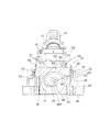
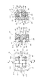
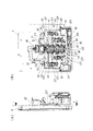
次に、上部可変入賞球装置60及び下部可変入賞球装置80の詳細な構成について図12乃至図19を参照して説明する。但し、上部可変入賞球装置60と下部可変入賞球装置80は、同一の構成部材によって構成されるため、便宜的に上部可変入賞球装置60の構成についてのみ説明を行う。図12は、上部可変入賞球装置60を示す斜視図である。図13は、上部可変入賞球装置60を示す正面図である。図14(A)は、図13のC−C線断面図であり、図14(B)は、図13のD−D線断面図である。図15は、開閉部材62を示す背面斜視図である。図16は、開閉部材62、ストッパー部材204、及び開閉係合部材214を示す背面斜視図である。図17は、後側構成体191の所定部分で切った上部可変入賞球装置60を示す背面図である。図18は、開閉係合部材214による開閉部材62の開閉動作を示す説明図である。図19は、ストッパー部材204による開閉部材62の開放保持動作を示す説明図である。   Next, detailed configurations of the upper variable winning ball device 60 and the lower variable winning ball device 80 will be described with reference to FIGS. However, since the upper variable winning ball apparatus 60 and the lower variable winning ball apparatus 80 are configured by the same constituent members, only the configuration of the upper variable winning ball apparatus 60 will be described for convenience. FIG. 12 is a perspective view showing the upper variable winning ball device 60. FIG. 13 is a front view showing the upper variable winning ball device 60. 14A is a cross-sectional view taken along the line CC in FIG. 13, and FIG. 14B is a cross-sectional view taken along the line DD in FIG. FIG. 15 is a rear perspective view showing the opening / closing member 62. FIG. 16 is a rear perspective view showing the opening / closing member 62, the stopper member 204, and the opening / closing engagement member 214. FIG. 17 is a rear view showing the upper variable winning ball device 60 cut at a predetermined portion of the rear structure 191. FIG. 18 is an explanatory view showing the opening / closing operation of the opening / closing member 62 by the opening / closing engagement member 214. FIG. 19 is an explanatory view showing an opening and holding operation of the opening / closing member 62 by the stopper member 204.

図12及び図13に示すように、上部可変入賞球装置60は、前記取付基板61を有しており、該取付基板61の外周部分には、遊技領域12にビス止めするための取付穴190が複数穿設されている。取付基板61の前面には、前述したように開閉部材62が個々に開閉自在に取り付けられた第1〜第4の可変入賞口61a〜61dが穿設されると共に、遊技球を第2可変入賞口61b側及び第3可変入賞口61c側に個々に誘導する左右一対の誘導突起61eが突設されている。一方、取付基板61の裏面側には、前述した開閉部材62の開放機構及び閉鎖機構を構成する各種構成部材を収容すると共に各誘導路64〜67を形成する前側及び後側の各構成体191,192が一体的に取り付けられている。   As shown in FIGS. 12 and 13, the upper variable winning ball device 60 has the mounting board 61, and a mounting hole 190 for screwing the game area 12 to the outer peripheral portion of the mounting board 61. Are perforated. As described above, first to fourth variable winning ports 61a to 61d, each having an openable / closable member 62 attached thereto as described above, are formed in the front surface of the mounting board 61, and the game balls are placed in the second variable prize. A pair of left and right guide protrusions 61e are individually provided on the mouth 61b side and the third variable winning opening 61c side. On the other hand, on the back surface side of the mounting substrate 61, various constituent members constituting the opening mechanism and the closing mechanism of the opening / closing member 62 described above are accommodated, and the front and rear constituent members 191 that form the guiding paths 64 to 67 are formed. , 192 are integrally attached.

図14(A)に示すように、開閉部材62は、支軸193(開閉支軸)を中心として回動自在に取付基板61に取り付けられる(同図中には、第1,第2の可変入賞口61a,61bと個々に連通する開閉部材62のみを図示)。開閉部材62は、図15に示すように、支軸193が軸支される軸支部194(開閉軸支部)と、可変入賞口(61a〜61b)を開閉する開閉板部195と、を備えている。開閉板部195の裏面は、開放状態で受け入れた遊技球を支承して後方に誘導する支承誘導面196として構成され、該支承誘導面196の下端部分は、軸支部194よりも下方に延設されている。   As shown in FIG. 14A, the opening / closing member 62 is attached to the mounting substrate 61 so as to be rotatable about a support shaft 193 (opening / closing support shaft) (in FIG. 14A, the first and second variable members). Only the opening / closing member 62 communicating with each of the winning openings 61a and 61b is shown). As shown in FIG. 15, the opening / closing member 62 includes a shaft support portion 194 (open / close shaft support portion) on which the support shaft 193 is supported, and an opening / closing plate portion 195 that opens and closes the variable winning openings (61 a to 61 b). Yes. The back surface of the opening / closing plate portion 195 is configured as a support guide surface 196 that supports a game ball received in an open state and guides it backward, and a lower end portion of the support guide surface 196 extends below the shaft support portion 194. Has been.

支承誘導面196の両側端には、それぞれ側壁面が立設されており、一側壁面には、開閉係合部材214との係合によって開閉部材62を開放する開放係合部197が形成されている。また、一側壁面側となる下方への延設部分には、開放係合部197と連続的に閉鎖保持部198が形成されている。閉鎖保持部198は、開閉係合部材214との係合によって開閉部材62の閉鎖状態を保持する。一方、他側壁面側となる下方への延設部分には、ストッパー部材204との係合によって開閉部材62の開放状態を保持する保持係合凹部199が形成されている。保持係合凹部199の側端部分には、開閉検出アーム200が延設されている。開閉検出アーム200は、開閉部材62の開閉動作に応じてフォトセンサ(図示しない)の光送受信部の遮断及び開放を行うことで、開閉部材62の開閉状態を検出する。   Side wall surfaces are erected on both side ends of the bearing guide surface 196, and an opening engagement portion 197 that opens the opening / closing member 62 by engagement with the opening / closing engagement member 214 is formed on one side wall surface. ing. Further, a closed holding portion 198 is formed continuously with the open engagement portion 197 at the downwardly extending portion on the side wall surface side. The closing holding part 198 holds the closing state of the opening / closing member 62 by engagement with the opening / closing engaging member 214. On the other hand, a holding engagement recess 199 that holds the open state of the opening / closing member 62 by engagement with the stopper member 204 is formed in a downwardly extending portion on the other side wall surface side. An open / close detection arm 200 is extended at a side end portion of the holding engagement recess 199. The open / close detection arm 200 detects the open / close state of the open / close member 62 by blocking and opening an optical transmission / reception unit of a photosensor (not shown) according to the open / close operation of the open / close member 62.

開閉板部195の上端部分には、支軸193を中心とした開閉部材62の回動バランスを調節することで、開閉部材62の開閉動作をスムーズに行わせる棒状錘201が埋設されている。即ち、開閉部材62の閉鎖時には、起立状態(垂直位置)にある開閉板部195の上端に棒状錘201が位置することで、開閉部材62の閉鎖状態を保つ一方、開閉部材62の開放時には、傾動する開閉板部195上端の棒状錘201がその重さによって開閉部材62の開放動作を促進する。また、開閉板部195の前面には、開放規制突片202が突設されている。開放規制突片202は、取付基板61の前面に突設された規制凸部61fとの当接によって開閉部材62の開放を規制する。   A bar-shaped weight 201 is embedded in the upper end portion of the opening / closing plate portion 195 so as to smoothly open and close the opening / closing member 62 by adjusting the rotational balance of the opening / closing member 62 around the support shaft 193. That is, when the opening / closing member 62 is closed, the rod-shaped weight 201 is positioned at the upper end of the opening / closing plate portion 195 in the standing state (vertical position), so that the opening / closing member 62 is kept closed, while when the opening / closing member 62 is opened, The bar-shaped weight 201 at the upper end of the tilting opening / closing plate portion 195 promotes the opening operation of the opening / closing member 62 by its weight. Further, an opening restricting protruding piece 202 protrudes from the front surface of the opening / closing plate portion 195. The opening restricting protrusion 202 restricts the opening of the opening / closing member 62 by contact with a restricting convex portion 61 f provided on the front surface of the mounting substrate 61.

なお、図15に示す開閉部材62は、正面から見て上部可変入賞球装置60(取付基板61)の右側に配置される可変入賞口(第3可変入賞口61c又は第4可変入賞口61d)と対応する開閉部材であり、正面から見て上部可変入賞球装置60(取付基板61)の左側に配置される可変入賞口(第1可変入賞口61a又は第2可変入賞口61b)と対応する開閉部材は、図15に示す開閉部材62と左右対称な形状をなすものである。即ち、図16に示すように、各可変入賞口61a〜61dに開閉部材62を取り付けた状態で、開放係合部197及び閉鎖保持部198は、上部可変入賞球装置60(取付基板61)の中央側に配置される一方、保持係合凹部199及び開閉検出アーム200は、上部可変入賞球装置60(取付基板61)の外側に配置されるようになっている。   The opening / closing member 62 shown in FIG. 15 is a variable winning opening (the third variable winning opening 61c or the fourth variable winning opening 61d) arranged on the right side of the upper variable winning ball apparatus 60 (mounting board 61) when viewed from the front. And corresponding to a variable winning opening (first variable winning opening 61a or second variable winning opening 61b) arranged on the left side of the upper variable winning ball apparatus 60 (mounting board 61) when viewed from the front. The opening / closing member is symmetrical to the opening / closing member 62 shown in FIG. That is, as shown in FIG. 16, in a state where the opening / closing member 62 is attached to each of the variable winning openings 61a to 61d, the opening engaging portion 197 and the closing holding portion 198 are provided on the upper variable winning ball apparatus 60 (attachment board 61). On the other hand, the holding engagement recess 199 and the opening / closing detection arm 200 are arranged on the outer side of the upper variable winning ball device 60 (attachment board 61).

また、上部可変入賞球装置60(取付基板61)の上側に配置される可変入賞口(第1可変入賞口61a及び第4可変入賞口61d)と対応する左右対称の開閉部材62は、それぞれ単一の支軸193によって取付基板61に軸支され、同様に、下側に配置される可変入賞口(第2可変入賞口61b及び第3可変入賞口61c)と対応する左右対称の開閉部材62もそれぞれ単一の支軸193によって取付基板61に軸支される。   In addition, the symmetrical open / close members 62 corresponding to the variable winning ports (the first variable winning port 61a and the fourth variable winning port 61d) arranged on the upper side of the upper variable winning ball device 60 (mounting substrate 61) are respectively single. A bilaterally symmetric opening / closing member 62 that is pivotally supported on the mounting board 61 by one support shaft 193 and corresponding to the variable winning opening (the second variable winning opening 61b and the third variable winning opening 61c) disposed on the lower side. Are also supported on the mounting substrate 61 by a single support shaft 193.

前側構成体191には、各可変入賞口61a〜61dと個々に連通する球誘導部203a〜203dが形成されている(図14(A)及び図17参照、但し、図14(A)中には第1,第2の可変入賞口61a,61bと個々に連通する球誘導部203a,203bのみを図示)。各球誘導部203a〜203d内には、それぞれ開閉部材92の開放状態を保持するストッパー部材204が設けられている。ストッパー部材204は、開放中の開閉部材62(支承誘導面196)から送り込まれる遊技球を受ける球受面部205と、該球受面部205の上端に設けられて支軸206(ストッパー支軸)を中心として回動自在にストッパー部材204を前側構成体191に取り付ける軸支部207(ストッパー軸支部)と、を備えている。   The front structure 191 is formed with ball guiding portions 203a to 203d that individually communicate with the variable winning openings 61a to 61d (see FIG. 14A and FIG. 17; however, in FIG. 14A) (Only the ball guiding portions 203a and 203b communicating with the first and second variable prize winning openings 61a and 61b are shown). A stopper member 204 that holds the open state of the opening / closing member 92 is provided in each of the ball guiding portions 203a to 203d. The stopper member 204 is provided with a ball receiving surface portion 205 that receives a game ball sent from the open / close member 62 (supporting guide surface 196), and a support shaft 206 (stopper support shaft) provided at the upper end of the ball receiving surface portion 205. A shaft support portion 207 (stopper shaft support portion) for attaching the stopper member 204 to the front side structural body 191 so as to be rotatable about the center is provided.

球受面部205の一側下端には、前記保持係合凹部199との係合によって開閉部材62の開放状態を保持する係合爪208が形成されている。また、球受面部205の裏面には、支軸206を中心としたストッパー部材204の回動バランスを調節することで、係合爪208と保持係合凹部199との係合状態を確実にする棒状錘209が一体的に取り付けられている。なお、ストッパー部材204は、開閉部材62と同様に、左側の可変入賞口(第1可変入賞口61a及び第2可変入賞口61b)と右側の可変入賞口(第3可変入賞口61c及び第4可変入賞口61d)とで左右対称な形状をなす。また、上側の可変入賞口(第1可変入賞口61a及び第4可変入賞口61d)と対応する左右対称のストッパー部材204は、それぞれ単一の支軸206によって前側構成体191に軸支され、同様に、下側の可変入賞口(第2可変入賞口61b及び第3可変入賞口61c)と対応する左右対称のストッパー部材204もそれぞれ単一の支軸206によって前側構成体191に軸支される。   An engaging claw 208 that holds the open state of the opening / closing member 62 by engaging with the holding engagement recess 199 is formed at one lower end of the ball receiving surface portion 205. Further, the engagement state between the engagement claw 208 and the holding engagement recess 199 is ensured on the back surface of the ball receiving surface portion 205 by adjusting the rotation balance of the stopper member 204 around the support shaft 206. A rod-shaped weight 209 is integrally attached. The stopper member 204 is similar to the opening / closing member 62 in that the left variable winning opening (the first variable winning opening 61a and the second variable winning opening 61b) and the right variable winning opening (the third variable winning opening 61c and the fourth variable winning opening 61c). The shape is symmetrical with the variable winning opening 61d). The left and right symmetrical stopper members 204 corresponding to the upper variable winning opening (the first variable winning opening 61a and the fourth variable winning opening 61d) are each pivotally supported by the front structure 191 by a single support shaft 206. Similarly, the left and right symmetrical stopper members 204 corresponding to the lower variable winning opening (the second variable winning opening 61b and the third variable winning opening 61c) are also pivotally supported by the front structure 191 by a single pivot 206, respectively. The

後側構成体192には、図17に示すように、各球誘導部203a〜203dと個々に連通する球誘導部210a〜210dが形成されており、各球誘導部210a〜210dの球排出口211a〜211dは、それぞれ後側構成体192の左右側壁部分に穿設されている。即ち、左側の可変入賞口(第1可変入賞口61a及び第2可変入賞口61b)と対応する球誘導部210a,210bは、それぞれ可変入賞口に入って各球誘導部203a,203bを通過した遊技球を遊技盤4裏面で左側に誘導する一方、右側の可変入賞口(第3可変入賞口61c及び第4可変入賞口61d)と対応する球誘導部210c,210dは、それぞれ可変入賞口に入って各球誘導部203c,203dを通過した遊技球を遊技盤4裏面で右側に誘導するようになっている。   As shown in FIG. 17, the rear structure body 192 is formed with ball guiding portions 210a to 210d that communicate with the respective ball guiding portions 203a to 203d, and the ball discharge ports of the respective ball guiding portions 210a to 210d. 211a to 211d are formed in the left and right side walls of the rear structure 192, respectively. That is, the ball guiding sections 210a and 210b corresponding to the left variable winning opening (the first variable winning opening 61a and the second variable winning opening 61b) enter the variable winning opening and pass through the respective ball guiding sections 203a and 203b. While the game ball is guided to the left side on the back side of the game board 4, the ball guiding portions 210c and 210d corresponding to the right variable winning port (the third variable winning port 61c and the fourth variable winning port 61d) are respectively variable variable winning ports. The game balls that have entered and passed through the ball guide portions 203c and 203d are guided to the right side on the back of the game board 4.

球誘導部210a〜210dには、それぞれ前記入賞口スイッチ63を取り付けるためのスイッチ取付部212が形成されている。スイッチ取付部212には、入賞口スイッチ63を着脱自在に取り付ける係合爪212aが設けられている。そして、入賞口スイッチ63の後端部と係合爪212aとの係合によって、入賞口スイッチ63の球検出穴63a(図14(A)参照)が各球誘導部210a〜210dと連通して取り付けられることで、球誘導部210a〜210dを通過した遊技球を個々に検出するようになっている。入賞口スイッチ63の球検出穴63aは、各球誘導部210a〜210dの通路断面形状に合った円形状であり、然も、スイッチ取付部212は、球検出穴63aが各球誘導部210a〜210dの通路傾斜に合わせて若干傾くように入賞口スイッチ63を取り付けるようになっている(図17参照)。このため、可変入賞口61a〜61dに入った遊技球は、入賞口スイッチ63による検出と球誘導部210a〜210dの通過がスムーズに行われるようになっている。   The ball guiding portions 210a to 210d are formed with switch attachment portions 212 for attaching the winning prize opening switch 63, respectively. The switch mounting portion 212 is provided with an engaging claw 212a for detachably attaching the winning opening switch 63. The ball detection hole 63a (see FIG. 14A) of the winning port switch 63 communicates with each of the ball guiding portions 210a to 210d by the engagement between the rear end portion of the winning port switch 63 and the engaging claw 212a. By being attached, the game balls that have passed through the ball guiding sections 210a to 210d are individually detected. The ball detection hole 63a of the winning opening switch 63 has a circular shape that matches the passage cross-sectional shape of each of the ball guiding portions 210a to 210d. However, the switch mounting portion 212 has the ball detection hole 63a that corresponds to each of the ball guiding portions 210a to 210a. A prize opening switch 63 is attached so as to be slightly inclined in accordance with the passage inclination of 210d (see FIG. 17). For this reason, the game balls that have entered the variable winning openings 61a to 61d are smoothly detected by the winning opening switch 63 and passed through the ball guiding sections 210a to 210d.

なお、前側構成体191に形成された球誘導部203aと後側構成体192に形成された球誘導部210aとにより、第1可変入賞口61aに入った遊技球を第1入賞球装置91の方向(第1チューリップ式入賞口91cの開放機構)に誘導する誘導路64が構成される。前側構成体191に形成された球誘導部203bと後側構成体192に形成された球誘導部210bとにより、第2可変入賞口61bに入った遊技球を第2入賞球装置92の方向(第2チューリップ式入賞口92cの開放機構)に誘導する誘導路65が構成される。前側構成体191に形成された球誘導部203cと後側構成体192に形成された球誘導部210cとにより、第3可変入賞口61cに入った遊技球を第3入賞球装置93の方向(第3チューリップ式入賞口93cの開放機構)に誘導する誘導路66が構成される。前側構成体191に形成された球誘導部203dと後側構成体192に形成された球誘導部210dとにより、第4可変入賞口61dに入った遊技球を第4入賞球装置94の方向(第4チューリップ式入賞口94bの開放機構)に誘導する誘導路67が構成される。   The game ball that has entered the first variable winning opening 61a is transferred to the first winning ball device 91 by the ball guiding portion 203a formed on the front component 191 and the ball guiding portion 210a formed on the rear component 192. A guide path 64 that guides in the direction (the opening mechanism of the first tulip type winning opening 91c) is configured. A game ball that has entered the second variable winning opening 61b is moved in the direction of the second winning ball device 92 (by the ball guiding portion 203b formed on the front structure 191 and the ball guiding portion 210b formed on the rear structure 192). A guiding path 65 for guiding to the second tulip-type winning opening 92c opening mechanism) is configured. A game ball that has entered the third variable winning opening 61c is moved in the direction of the third winning ball device 93 (by the ball guiding portion 203c formed on the front component 191 and the ball guiding portion 210c formed on the rear component 192). A guide path 66 for guiding to the third tulip-type winning opening 93c) is configured. A game ball that has entered the fourth variable winning opening 61d is moved in the direction of the fourth winning ball device 94 by the ball guiding portion 203d formed on the front component 191 and the ball guiding portion 210d formed on the rear component 192 ( A guide path 67 for guiding to the fourth tulip type winning opening 94b) is configured.

また、後側構成体192の中央(各球誘導部203a,203d間、及び各球誘導部203b,203c間)には、図14(B)及び図17に示すように、上下方向に延びる落下通路213が形成されている。落下通路213上端の開口は、前記特別通路部50からの遊技球を受け入れる球入口213aとして形成され、落下通路213下端の開口は、当該落下通路213を通過した遊技球を下方に排出する球出口213bとして形成されている。即ち、上部可変入賞球装置60の落下通路213は、球入口213aで特別通路部50を通過した遊技球を受け入れ、球出口213bから下部可変入賞球装置80に向けて遊技球を排出する。一方、下部可変入賞球装置80の落下通路213は、球入口213aで上部可変入賞球装置60を通過した遊技球を受け入れ、球出口213bから回収通路232(図22(B)参照)に遊技球を排出する。   Further, as shown in FIG. 14B and FIG. 17, a drop extending in the vertical direction is placed at the center of the rear structure 192 (between the ball guiding portions 203a and 203d and between the ball guiding portions 203b and 203c). A passage 213 is formed. An opening at the upper end of the drop passage 213 is formed as a ball inlet 213a for receiving a game ball from the special passage portion 50, and an opening at the lower end of the drop passage 213 is a ball outlet for discharging the game ball that has passed through the drop passage 213 downward. It is formed as 213b. That is, the falling passage 213 of the upper variable winning ball device 60 receives the game ball that has passed through the special passage portion 50 at the ball inlet 213a and discharges the gaming ball from the ball outlet 213b toward the lower variable winning ball device 80. On the other hand, the falling passage 213 of the lower variable winning ball device 80 receives the game ball that has passed through the upper variable winning ball device 60 at the ball inlet 213a, and enters the collection passage 232 from the ball outlet 213b (see FIG. 22B). Is discharged.

落下通路213内には、各球誘導部203a,203d間及び各球誘導部203b,203c間となる上下二箇所にそれぞれ左右対称形状の開閉係合部材214が設けられている。開閉係合部材214は、軸支部214aを備えると共に該軸支部214aが支軸215に回動自在に軸支されることで、支軸215を中心として回動自在に設けられている。各球誘導部203a,203d間の左側の開閉係合部材214は、第1可変入賞口61aと対応するものであり、各球誘導部203a,203d間の右側の開閉係合部材214は、第4可変入賞口61dと対応するものである。一方、各球誘導部203b,203c間の左側の開閉係合部材214は、第2可変入賞口61bと対応するものであり、各球誘導部203b,203c間の右側の開閉係合部材214は、第3可変入賞口61cと対応するものである。   In the drop passage 213, symmetrical opening / closing engagement members 214 are provided at two upper and lower positions between the ball guiding portions 203a and 203d and between the ball guiding portions 203b and 203c. The opening / closing engagement member 214 includes a shaft support portion 214a and is rotatably provided around the support shaft 215 by the shaft support portion 214a being rotatably supported by the support shaft 215. The left opening / closing engagement member 214 between the ball guiding portions 203a, 203d corresponds to the first variable winning opening 61a, and the right opening / closing engagement member 214 between the ball guiding portions 203a, 203d is This corresponds to the 4 variable prize winning opening 61d. On the other hand, the left opening / closing engagement member 214 between the ball guiding portions 203b and 203c corresponds to the second variable winning opening 61b, and the right opening / closing engagement member 214 between the ball guiding portions 203b and 203c is This corresponds to the third variable winning opening 61c.

なお、上側の可変入賞口(第1可変入賞口61a及び第4可変入賞口61d)と対応する左右対称の開閉係合部材214は、それぞれ単一の支軸215によって前側構成体191と後側構成体192との間に軸支され、同様に、下側の可変入賞口(第2可変入賞口61b及び第3可変入賞口61c)と対応する左右対称の開閉係合部材214もそれぞれ単一の支軸215によって前側構成体191と後側構成体192との間に軸支される。   The left and right symmetrical opening / closing engagement members 214 corresponding to the upper variable winning opening (the first variable winning opening 61a and the fourth variable winning opening 61d) are respectively connected to the front structure 191 and the rear by a single support shaft 215. Similarly, each of the bilaterally symmetric opening / closing engaging members 214 corresponding to the lower variable winning opening (the second variable winning opening 61b and the third variable winning opening 61c) is also single. Are supported between the front side structural body 191 and the rear side structural body 192.

開閉係合部材214の軸支部214aには、前側構成体191に形成された球誘導部(203a〜203d)内に配されて開閉部材62の開放係合部197及び閉鎖保持部198と係合する係合突起部216と、後側構成体192に形成された落下通路213内に配されて当該落下通路213内を落下する遊技球と当接する当接部217とが突設されると共に、支軸215を中心とした開閉係合部材214の回動バランスを調節する棒状錘218が埋設されている。なお、当接部217は、落下通路213を落下する遊技球との当接部分が当該遊技球を受け止める球受面として形成されている。棒状錘218は、開閉部材62の開放保持状態が解除されたときに、その自重によって開閉係合部材214を回動して当接部217を落下通路213内で傾動位置から起立位置に移行する。   The shaft support portion 214 a of the opening / closing engagement member 214 is disposed in a ball guiding portion (203 a to 203 d) formed in the front structure 191 and engages with the opening engagement portion 197 and the closing holding portion 198 of the opening / closing member 62. And an abutting portion 217 arranged in a drop passage 213 formed in the rear side structure 192 and abutting with a game ball falling in the drop passage 213, A bar-shaped weight 218 for adjusting the rotational balance of the opening / closing engagement member 214 around the support shaft 215 is embedded. In addition, the contact part 217 is formed as a ball receiving surface that receives the game ball at a contact part with the game ball falling through the drop passage 213. When the opening / holding state of the opening / closing member 62 is released, the bar-shaped weight 218 rotates the opening / closing engagement member 214 by its own weight, and moves the contact portion 217 from the tilting position to the standing position in the drop passage 213. .

また、落下通路213の後側内壁面には、落下通路213内を落下する遊技球を受けてこれを当接部217側(落下通路213の前側)に誘導する誘導突起部213cが突設されている(図14(B)及び図17参照)。誘導突起部213cは、上側及び下側の可変入賞口(可変入賞口61a,61d及び可変入賞口61b,61c)と個々に対応するよう上下二箇所に突設されている。   In addition, on the rear inner wall surface of the drop passage 213, a guide projection 213c is provided so as to receive a game ball falling in the drop passage 213 and guide it to the contact portion 217 side (front side of the drop passage 213). (See FIG. 14B and FIG. 17). The guide protrusions 213c are provided at two locations in the upper and lower sides so as to correspond to the upper and lower variable winning ports (variable winning ports 61a and 61d and variable winning ports 61b and 61c), respectively.

ここで、開閉係合部材214による開閉部材62の開閉動作及びストッパー部材204による開閉部材62の開放保持動作について説明する。先ず、開閉部材62(可変入賞口61a〜61d)の閉鎖状態では、図18(A)のE−E線断面図となる図18(B)に示すように、開閉係合部材214の係合突起部216は、開閉部材62の開放係合部197及び閉鎖保持部198との係合を解除した状態にある。但し、この状態から振動等の外力によって、支軸193を中心として可変入賞口(61a〜61d)を開放する方向(図18(B)の反時計方向)に開閉部材62が回動した場合には、閉鎖保持部198が係合突起部216と係合して開閉部材62の回動を規制することで、可変入賞口(61a〜61d)の閉鎖状態が保持される。即ち、開閉部材62は、閉鎖保持部198と係合突起部216との係合によって若干の遊びを持って閉鎖状態が保持されるようになっている。   Here, the opening and closing operation of the opening and closing member 62 by the opening and closing engagement member 214 and the opening and holding operation of the opening and closing member 62 by the stopper member 204 will be described. First, in the closed state of the opening / closing member 62 (variable winning openings 61a to 61d), as shown in FIG. 18B, which is a cross-sectional view taken along the line EE of FIG. The projecting portion 216 is in a state in which the engagement with the opening engagement portion 197 and the closing holding portion 198 of the opening / closing member 62 is released. However, when the opening / closing member 62 is rotated from this state by an external force such as vibration in a direction (a counterclockwise direction in FIG. 18B) that opens the variable winning opening (61a to 61d) around the support shaft 193. The closed holding portion 198 engages with the engaging protrusion 216 and restricts the rotation of the opening / closing member 62, whereby the closed state of the variable prize opening (61a to 61d) is held. That is, the opening / closing member 62 is held in a closed state with a slight play by the engagement between the closing holding portion 198 and the engaging protrusion 216.

また、開閉部材62(可変入賞口61a〜61d)の閉鎖状態では、開閉係合部材214の当接部217は、図14(B)に示すように、落下通路213内で起立位置にある。また、ストッパー部材204の係合爪208は、図19(A)のG−G線断面図となる図19(B)に示すように、開閉部材62の保持係合凹部199との係合を解除した状態にある。   In the closed state of the opening / closing member 62 (variable winning ports 61a to 61d), the contact portion 217 of the opening / closing engagement member 214 is in an upright position in the drop passage 213 as shown in FIG. Further, the engagement claw 208 of the stopper member 204 engages with the holding engagement recess 199 of the opening / closing member 62 as shown in FIG. It is in a released state.

そして、特別通路部50から送り込まれた遊技球が落下通路213内を自然落下によって通過すると、その通過に伴って当該遊技球が当接部217を押し下げて、当接部217を起立位置から傾動位置に移行する。これにより、開閉係合部材214は、支軸215を中心として図18(B)の時計方向(図18(C)の反時計方向)に回動して係合突起部216が押し上げられる。押し上げられた係合突起部216は、開放係合部197と係合することで、図18(A)のF−F線断面図となる図18(C)に示すように、支軸193を中心として開閉部材62を図18(C)の時計方向に回動して可変入賞口(61a〜61d)を開放する。   Then, when the game ball sent from the special passage portion 50 passes through the fall passage 213 by natural fall, the game ball pushes down the contact portion 217 along with the passage, and the contact portion 217 is tilted from the standing position. Move to position. As a result, the opening / closing engagement member 214 rotates about the support shaft 215 in the clockwise direction in FIG. 18B (counterclockwise in FIG. 18C), and the engagement protrusion 216 is pushed up. As shown in FIG. 18C, which is a cross-sectional view taken along the line FF of FIG. 18A, the pushed-up engaging protrusion 216 engages with the release engaging portion 197, and as shown in FIG. The opening / closing member 62 is rotated in the clockwise direction in FIG.

また、上記した係合突起部216と開放係合部197との係合によって開閉部材62が可変入賞口(61a〜61d)の開放位置まで回動すると、図19(A)のH−H線断面図となる図19(C)に示すように、ストッパー部材204は、棒状錘209による回動バランスに基づいて支軸206を中心として図19(C)の時計方向に回動し、係合爪208が保持係合凹部199と係合する。これにより、開閉部材62は、開放状態が保持される。なお、このような開放状態において、開閉係合部材214は、係合突起部216が開閉部材62の閉鎖保持部198に押し上げられた状態にあり、落下通路213内の当接部217は、押し下げられた位置に保持される。   Further, when the opening / closing member 62 is rotated to the open position of the variable winning opening (61a to 61d) by the engagement of the engagement protrusion 216 and the release engagement portion 197, the HH line in FIG. As shown in FIG. 19C, which is a cross-sectional view, the stopper member 204 rotates around the support shaft 206 in the clockwise direction in FIG. 19C based on the rotation balance by the rod-shaped weight 209, and engages. The claw 208 engages with the holding engagement recess 199. Thereby, the open / close member 62 is kept open. In such an open state, the opening / closing engagement member 214 is in a state where the engagement protrusion 216 is pushed up by the closing holding portion 198 of the opening / closing member 62, and the contact portion 217 in the drop passage 213 is pushed down. Held in place.

その後、開放中の可変入賞口(61a〜61d)に遊技球が入賞すると、当該遊技球が開閉部材62の支承誘導面196上を流下して後方(球誘導部203a〜203d内)に送り込まれる。そして、球誘導部(203a〜203d)内に送り込まれた遊技球が球受面部205を後方に押し込むことで、ストッパー部材204が支軸206を中心として図19(C)の反時計方向(図19(B)の時計方向)に回動し、係合爪208と保持係合凹部199との係合を解除して開閉部材62の開放保持状態を解除する。このとき、開閉部材62は、支承誘導面196の下方延設部分(軸支部194よりも下方に延設された部分)となる閉鎖誘導面部に遊技球が転がり込むことで支軸193を中心として図19(B)の反時計方向に回動し、可変入賞口(61a〜61d)を閉鎖する。また、これに伴い、開閉係合部材214は、棒状錘218による回動バランスに基づいて支軸215を中心として図19(B)の時計方向に回動し、当接部217が落下通路213内で起立位置に移行する。   Thereafter, when a game ball wins the open variable winning opening (61a to 61d), the game ball flows down on the support guide surface 196 of the opening / closing member 62 and is sent to the rear (in the ball guide portions 203a to 203d). . Then, the game ball sent into the ball guiding portions (203a to 203d) pushes the ball receiving surface portion 205 backward, so that the stopper member 204 is centered on the support shaft 206 in the counterclockwise direction of FIG. 19 (B) clockwise), the engagement between the engagement claw 208 and the holding engagement recess 199 is released, and the open / close state of the opening / closing member 62 is released. At this time, the opening / closing member 62 is shown in FIG. It rotates counterclockwise at 19 (B) and closes the variable prize winning openings (61a to 61d). Accordingly, the opening / closing engagement member 214 rotates about the support shaft 215 in the clockwise direction in FIG. 19B based on the rotation balance by the rod-shaped weight 218, and the contact portion 217 falls in the drop passage 213. Move to the standing position.

ところで、以上説明した開閉係合部材214による開閉部材62の開放動作において、本実施形態の構成では、遊技球の自重によって開閉部材を開放する従来の構成に比べて、素早いタイミングで開閉部材62を開放するようになっている。具体的には、図20に示すように、遊技球を自然落下させる落下通路213によって球通路を構成すると共に、落下通路213内での当接部217の突出寸法L3を遊技球の直径寸法L2よりも小さく設定している。そして、落下通路213を自然落下する遊技球の衝撃力を当接部217に加えることで開閉係合部材214を回動し、回動する開閉係合部材214の係合突起部216と開閉部材62との係合によって開閉部材62を開放する。   By the way, in the opening operation of the opening / closing member 62 by the opening / closing engaging member 214 described above, in the configuration of the present embodiment, the opening / closing member 62 is moved at a faster timing than the conventional configuration in which the opening / closing member is opened by the weight of the game ball. It is designed to be opened. Specifically, as shown in FIG. 20, a ball passage is constituted by a drop passage 213 that naturally drops a game ball, and a protrusion dimension L3 of the contact portion 217 in the drop passage 213 is set to a diameter dimension L2 of the game ball. Is set smaller. Then, by applying the impact force of the game ball that naturally falls in the drop passage 213 to the contact portion 217, the opening / closing engagement member 214 is rotated, and the engagement protrusion 216 and the opening / closing member of the rotating opening / closing engagement member 214 are rotated. The opening / closing member 62 is opened by the engagement with 62.

このため、遊技球を当接部217上に載せた後に遊技球の自重によって当接部217を下方に押し込んで開閉部材62を徐々に開放位置に移行するような構成と違い、遊技球の衝撃力が当接部217に加わった瞬間に開閉係合部材214を回動して瞬時に開閉部材62を開放することができる。その結果、素早いタイミングで開閉部材62を開放することができる。また、この構成によれば、当接部217が配される球通路(落下通路213)を傾斜通路とすることなく、然も当接部217を遊技球よりも大きな形状で形成することがないので、可変入賞球装置(上部可変入賞球装置60、下部可変入賞球装置80)の大型化を回避でき、ひいては可変入賞球装置の設計自由度を低下させることがない。   For this reason, unlike the configuration in which the game ball is placed on the contact portion 217 and then the contact portion 217 is pushed downward by the weight of the game ball to gradually move the opening / closing member 62 to the open position. The opening / closing engagement member 214 can be rotated at the moment when a force is applied to the contact portion 217 to open the opening / closing member 62 instantaneously. As a result, the opening / closing member 62 can be opened at a quick timing. Further, according to this configuration, the ball passage (falling passage 213) in which the contact portion 217 is arranged is not an inclined passage, and the contact portion 217 is not formed in a shape larger than the game ball. Therefore, it is possible to avoid an increase in the size of the variable winning ball device (upper variable winning ball device 60, lower variable winning ball device 80), and consequently, the design freedom of the variable winning ball device is not reduced.

また、落下通路213は、その通路幅寸法L1が遊技球の直径寸法L2(=11mm)よりも若干大きく設定されている。このため、遊技球が落下通路213の内壁に衝突する頻度を軽減することができ、遊技球の落下速度が低下することを極力回避できる。従って、遊技球の自然落下による衝撃力を極力大きな力として当接部217に加わえることができ、より一層素早いタイミングで開閉部材62を開放することができる。なお、落下通路213の通路幅寸法L1は、2個の遊技球が同時に通過することなく、落下通路213内を1個の遊技球がスムーズに通過し得る寸法であればよい。具体的に、実施形態中では、遊技球の直径寸法L2よりも1mm大きい12mmが通路幅寸法L1に設定されている。   Further, the drop passage 213 is set such that the passage width dimension L1 thereof is slightly larger than the diameter dimension L2 (= 11 mm) of the game ball. For this reason, the frequency with which a game ball collides with the inner wall of the fall passage 213 can be reduced, and a fall of the fall speed of the game ball can be avoided as much as possible. Therefore, the impact force caused by the natural fall of the game ball can be applied to the contact portion 217 as much as possible, and the opening / closing member 62 can be opened at a much quicker timing. The passage width dimension L1 of the drop passage 213 may be a dimension that allows one game ball to pass smoothly through the drop passage 213 without passing two game balls simultaneously. Specifically, in the embodiment, 12 mm which is 1 mm larger than the diameter dimension L2 of the game ball is set as the passage width dimension L1.

また、落下通路213の内壁には、当該落下通路213を落下する遊技球との衝突によって当該遊技球を当接部217の軸支部214a側となる部分に誘導する誘導突起部213cが突設されている。これにより、球入口213aに入った遊技球(図20に示すP1の状態)は、その後、落下通路213内の誘導突起部213cと衝突して(図20に示すP2の状態)、落下方向が鉛直方向から若干傾いた当接部217の軸支部214a側の方向に切り替わり、軸支部214a側となる部分に落下する(図20に示すP3の状態)。このため、遊技球の衝撃力を効率良く開閉係合部材214の回動力に変換することができ(図20に示すP4の状態)、開閉係合部材214の回動速度を高めることで、より一層素早いタイミングでの開閉部材62の開放が可能になる。   In addition, a guide projection 213c is provided on the inner wall of the drop passage 213 so as to guide the game ball to a portion of the contact portion 217 on the shaft support portion 214a side by collision with the game ball falling through the drop passage 213. ing. Thereby, the game ball (P1 state shown in FIG. 20) entering the ball inlet 213a subsequently collides with the guide protrusion 213c in the drop passage 213 (P2 state shown in FIG. 20), and the falling direction is changed. The contact portion 217 slightly tilted from the vertical direction is switched to the direction of the shaft support portion 214a and falls to a portion on the shaft support portion 214a side (state P3 shown in FIG. 20). For this reason, the impact force of the game ball can be efficiently converted into the rotational force of the opening / closing engagement member 214 (state of P4 shown in FIG. 20), and the rotation speed of the opening / closing engagement member 214 can be increased. The opening / closing member 62 can be opened at a faster timing.

また、当接部217は、落下通路213を落下する遊技球との当接部分が当該遊技球を受け止める球受面として形成されると共に、先端側に向って若干下り傾斜して配置されている。言い換えれば、当接部217は、誘導突起部213cと衝突した遊技球の落下方向と垂直面となるように落下通路213内に配置されている。これにより、誘導突起部213cに衝突して落下通路213内での落下方向が鉛直方向から若干軸支部214a側に傾いた遊技球は、球受面に対して直角となる方向で当接部217に当接する。このため、遊技球の衝撃力を効率良く当接部217に加えることができる。   The contact portion 217 is formed such that a contact portion with a game ball falling through the fall passage 213 is formed as a ball receiving surface for receiving the game ball, and is slightly inclined downward toward the tip side. . In other words, the contact portion 217 is disposed in the drop passage 213 so as to be in a plane perpendicular to the drop direction of the game ball colliding with the guide protrusion 213c. As a result, a game ball that has collided with the guide projection 213c and whose fall direction in the fall passage 213 is slightly inclined from the vertical direction toward the pivotal support 214a is a contact portion 217 in a direction perpendicular to the ball receiving surface. Abut. For this reason, the impact force of a game ball can be applied to the contact part 217 efficiently.

また、誘導突起部213cは、当接部217と対向する落下通路213の内壁面であり、且つ軸支部214aの配置位置よりも上方となる箇所に設けられる。これにより、誘導突起部213cに遊技球を衝突させた後に、当該遊技球を当接部217に誘導することができるので、誘導突起部213cと当接部217との間で遊技球が挟み込まれて落下通路213内で球詰りが生じることを防止できる。なお、実施形態中では、軸支部214aの中心から上方に高さ寸法L4(=11.4mm)の位置に誘導突起部213cが突設されている。   In addition, the guide protrusion 213c is provided on the inner wall surface of the drop passage 213 facing the contact portion 217 and at a position above the position where the shaft support portion 214a is disposed. As a result, the game ball can be guided to the contact portion 217 after the game ball collides with the guide projection portion 213c, so that the game ball is sandwiched between the guide projection portion 213c and the contact portion 217. Therefore, it is possible to prevent clogging of the balls in the falling passage 213. In the embodiment, the guide projection 213c protrudes upward from the center of the shaft support 214a at a height dimension L4 (= 11.4 mm).

また、落下通路213内で誘導突起部213c上に遊技球が停留して球詰りが生じることを防止できるように、誘導突起部213cの突出寸法L5は、落下通路213の通路幅寸法から遊技球の直径寸法L2を減算した値よりも小さい値に設定されている。具体的に、実施形態中では、誘導突起部213cが突設された部分に対応する通路幅寸法が14mmに設定され、該通路幅寸法から遊技球の直径寸法L2(=11mm)を減算した値は3mmとなる。これに対応して、誘導突起部213cの突出寸法L5は、3mmよりも小さい2mmに設定している。従って、誘導突起部213cの先端部分から対向する落下通路213の内壁面までの寸法L6は、遊技球の直径寸法L2よりも大きい12mmとなる。これにより、遊技球は、誘導突起部213c上に停留することなくスムーズに当接部217上に落下するようになっている。   Further, the projecting dimension L5 of the guiding projection 213c is determined from the path width dimension of the dropping path 213 so that it is possible to prevent the game ball from stopping on the guiding projection 213c in the falling path 213. Is set to a value smaller than the value obtained by subtracting the diameter dimension L2. Specifically, in the embodiment, the passage width dimension corresponding to the portion where the guide protrusion 213c is projected is set to 14 mm, and the value obtained by subtracting the diameter dimension L2 (= 11 mm) of the game ball from the passage width dimension Is 3 mm. Correspondingly, the projection dimension L5 of the guide projection 213c is set to 2 mm, which is smaller than 3 mm. Accordingly, the dimension L6 from the tip end portion of the guide protrusion 213c to the inner wall surface of the falling passage 213 that is opposite is 12 mm, which is larger than the diameter L2 of the game ball. As a result, the game ball is smoothly dropped on the contact portion 217 without stopping on the guide protrusion 213c.

なお、本実施形態では、遊技球の衝撃力が当接部217に加わることで、開閉係合部材214が破損することを回避するために、高強度を有する材料(例えば、ガラス繊維を含有するポリカーボネイト等)によって開閉係合部材214を形成している。また、遊技球の衝撃力が最も大きくかかる当接部217の球受面の基部(軸支部214a側の部分)の強度を高めるために、球受面の肉厚部分が軸支部214a側から先端側に向けて徐々に細くなるテーパー形状に形成している。   In the present embodiment, a material having high strength (for example, glass fiber is included) in order to prevent the opening / closing engagement member 214 from being damaged by the impact force of the game ball being applied to the contact portion 217. The opening / closing engagement member 214 is formed of polycarbonate or the like. Further, in order to increase the strength of the base of the ball receiving surface of the contact portion 217 (the portion on the shaft support portion 214a side) where the impact force of the game ball is the largest, the thick portion of the ball receiving surface is advanced from the shaft support portion 214a side. It is formed in a tapered shape that gradually narrows toward the side.

ところで、上記した開閉係合部材214による開閉部材62の開放動作において、落下通路213内を落下する遊技球が当接部217と当接するタイミングで、遊技領域12を流下する遊技球が開閉部材62の前方を通過した場合、開閉部材62前方の遊技球が開閉係合部材214の回動動作に伴う開閉係合部材214(係合突起部216)と開閉部材62(開放係合部197)との係合を妨げることになる。そして、最悪の場合、遊技球が落下通路213を通過したにも拘わらず、開閉部材62が開放しないことが生じる虞がある。そこで、図21に示す変形例の構成とすることで、確実に開閉部材62を開放するようにしてもよい。以下、図21を参照して変形例の構成について説明する。なお、上記した実施形態と同一の構成については、便宜的に同一の符号を付し、その詳細な説明を省略する。   By the way, in the opening operation of the opening / closing member 62 by the opening / closing engagement member 214 described above, the game ball flowing down the game area 12 is opened / closed at the timing when the game ball falling in the drop passage 213 contacts the contact portion 217. When the game ball passes in front of the opening / closing member 62, the opening / closing engagement member 214 (engagement projection 216) and the opening / closing member 62 (open engagement portion 197) that accompany the turning operation of the opening / closing engagement member 214 Will be hindered. In the worst case, the open / close member 62 may not be opened although the game ball passes through the drop passage 213. Therefore, the opening / closing member 62 may be reliably opened by adopting the configuration of the modification shown in FIG. Hereinafter, the configuration of the modification will be described with reference to FIG. In addition, about the same structure as above-mentioned embodiment, the same code | symbol is attached | subjected for convenience and the detailed description is abbreviate | omitted.

図21に示すように、落下通路213の後側内壁面(当接部217との対向面となる内壁)には、誘導突起部213cの下方となる部分に押込突起部213dが突設されている。なお、押込突起部213dは、後述する開閉係合部材214’の軸支部214aよりも下方位置に設けられると共に、誘導突起部213cと同様に、上側及び下側の可変入賞口(可変入賞口61a,61d及び可変入賞口61b,61c)と個々に対応するよう上下二箇所に突設されている。実施形態中では、軸支部214aの中心から下方に高さ寸法L7(=3.4mm)の位置に押込突起部213dが突設されている。   As shown in FIG. 21, on the rear inner wall surface of the drop passage 213 (the inner wall that faces the abutting portion 217), a pushing projection portion 213d protrudes from a portion below the guide projection portion 213c. Yes. The pushing protrusion 213d is provided at a lower position than a shaft support 214a of an opening / closing engagement member 214 ′ to be described later, and similarly to the guide protrusion 213c, the upper and lower variable winning openings (variable winning openings 61a). , 61d and the variable prize winning openings 61b, 61c). In the embodiment, a pushing projection 213d is projected from the center of the shaft support 214a at a position of a height dimension L7 (= 3.4 mm).

一方、変形例の開閉係合部材214’は、開閉係合部材214と同様に、支軸215に回動自在に軸支される軸支部214aを備え、該軸支部214aには、開閉部材62(開放係合部197及び閉鎖保持部198)と係合する係合突起部216と、落下通路213内を落下する遊技球と当接する当接部217’とが突設されると共に、支軸215を中心とした開閉係合部材214の回動バランスを調節する棒状錘218が埋設されている。開閉係合部材214’ の当接部217’は、その上面が凹状の湾曲形状をなし、当接部217’の先端部分は、押込凸部217’aを構成している。   On the other hand, the open / close engaging member 214 ′ of the modified example includes a shaft support portion 214a rotatably supported on the support shaft 215, like the open / close engagement member 214, and the open / close member 62 is provided on the shaft support portion 214a. An engagement projection 216 that engages with the (open engagement portion 197 and the closing holding portion 198) and an abutment portion 217 ′ that abuts against a game ball that falls in the drop passage 213 are provided in a protruding manner. A bar-shaped weight 218 that adjusts the rotational balance of the opening / closing engagement member 214 centered on 215 is embedded. The contact portion 217 ′ of the opening / closing engagement member 214 ′ has a concave curved upper surface, and the tip portion of the contact portion 217 ′ constitutes a pressing projection 217 ′ a.

しかして、誘導突起部213cと衝突して当接部217’上に落下した遊技球は、その後の下方落下によって当接部217’を下方に押し下げ、開閉部材62を開放する方向に開閉係合部材214’を回動させる。その後、遊技球は、押込突起部213dとの当接によって軸支部214a側に押し込まれ、開閉係合部材214’を回動する力を強める(図21に示すP5の状態)。また、このとき、当接部217’の先端部分に設けられた押込凸部217’aは、押込突起部213dによって押し込まれた遊技球との当接によって当該遊技球による当接部217’の押し込みを助長する。これにより、遊技球が当接部217’に当接するのと同じタイミングで、閉鎖位置にある開閉部材62の前方に遊技球が落下するような場合(図21に示すP6の状態)でも、押込突起部213dによる遊技球の押し込みによって開閉部材62前方の遊技球を押し払って開閉部材を開放することができる(図21に示すP7,P8の状態)。   Thus, the game ball that has collided with the guide protrusion 213c and dropped onto the contact portion 217 'is pushed down on the contact portion 217' by the subsequent downward drop, and is opened and closed in a direction to open the opening and closing member 62. The member 214 ′ is rotated. Thereafter, the game ball is pushed into the shaft support 214a side by contact with the push-in protrusion 213d, and the force for rotating the opening / closing engagement member 214 'is increased (state P5 shown in FIG. 21). Further, at this time, the pushing protrusion 217′a provided at the tip of the abutting portion 217 ′ is brought into contact with the game ball pushed by the pushing projection 213d, so that Assist in pushing. Thus, even when the game ball falls in front of the opening / closing member 62 in the closed position at the same timing as the game ball contacts the contact portion 217 ′ (P6 state shown in FIG. 21), the push-in is performed. By pushing the game ball by the protrusion 213d, the game ball in front of the opening / closing member 62 can be pushed away to open the opening / closing member (states P7 and P8 shown in FIG. 21).

なお、押込突起部213dは、開閉部材62が開放位置に移行した状態(図21に示すP8の状態)で、当該押込突起部213dの先端部分から当接部217’が遊技球と当接する当接先端部分(押込凸部217’a)までの寸法L9が遊技球の直径寸法L2(=11mm)よりも若干大きくなる位置に設けられている。これにより、押込突起部213dによる遊技球の押し込みをより効率的に行わせることができる。なお、当接部217’の当接先端部分とは、落下通路213を落下する遊技球が当接部217’と当接する部分において、最も当接部217’の先端部分に近い部分のことをいい、実施形態中では、当接部217’先端の押込凸部217’aとなる。また、実施形態中では、押込突起部213dの先端部分から当接部217’が遊技球と当接する当接先端部分(押込凸部217’a)までの寸法L9が11.3mmとなるように押込突起部213dを設けている。但し、押込突起部213dの突出寸法L8は、1.8mmに設定されている。   Note that the pushing protrusion 213d is in a state in which the abutting portion 217 ′ comes into contact with the game ball from the tip end portion of the pushing protrusion 213d in a state where the opening / closing member 62 has shifted to the open position (P8 shown in FIG. 21). The dimension L9 up to the contact tip portion (pushing protrusion 217′a) is provided at a position where it is slightly larger than the diameter L2 (= 11 mm) of the game ball. Thereby, pushing of the game ball by the pushing protrusion 213d can be performed more efficiently. The contact tip portion of the contact portion 217 ′ is the portion closest to the tip portion of the contact portion 217 ′ in the portion where the game ball falling through the drop passage 213 contacts the contact portion 217 ′. In the embodiment, it is the pressing convex portion 217′a at the tip of the contact portion 217 ′. In the embodiment, the dimension L9 from the tip portion of the pushing projection 213d to the abutting tip portion (pushing projection 217′a) where the abutting portion 217 ′ abuts on the game ball is 11.3 mm. A pressing projection 213d is provided. However, the protrusion dimension L8 of the pushing protrusion 213d is set to 1.8 mm.

次に、遊技盤4裏面での遊技球の球流れについて図22を参照して説明する。図22(A)は球通路カバー体220を示す側面図であり、図22(B)は図22(A)のI−I線断面図である。   Next, the flow of game balls on the back of the game board 4 will be described with reference to FIG. 22A is a side view showing the ball passage cover body 220, and FIG. 22B is a cross-sectional view taken along the line II of FIG. 22A.

図22(A)に示すように、遊技盤4の裏面には、遊技領域12内の各種入賞口に入った遊技球を誘導する球通路が形成された球通路カバー体220が取り付けられている。球通路カバー体220には、図22(B)に示すように、入賞振分装置40の排出通路部51に送り込まれた遊技球を受け入れてこれを回収する回収通路221と、入賞振分装置40の特別通路部50と上部可変入賞球装置60の落下通路213とを連通する連通通路222と、が形成されている。しかして、入賞口41に入った後に球受回転体47の振り分けによって排出通路部51に送り込まれた遊技球は、回収通路221を通って回収される。一方、入賞口41に入った後に球受回転体47の振り分けによって特別通路部50に送り込まれた遊技球は、連通通路222を通って上部可変入賞球装置60の落下通路213(球入口213a)に送り込まれる。   As shown in FIG. 22 (A), on the back surface of the game board 4, a ball passage cover body 220 in which ball passages for guiding game balls entering various winning holes in the game area 12 are formed is attached. . As shown in FIG. 22 (B), the ball passage cover body 220 receives a game ball sent to the discharge passage portion 51 of the winning distribution device 40 and collects it, and a winning distribution device. A communication passage 222 that connects the 40 special passage portions 50 and the drop passage 213 of the upper variable winning ball apparatus 60 is formed. Thus, the game balls that have been sent to the discharge passage portion 51 by sorting the ball receiving rotor 47 after entering the winning opening 41 are collected through the collection passage 221. On the other hand, the game balls that have been sent to the special passage portion 50 by sorting the ball receiving and rotating body 47 after entering the winning opening 41 pass through the communication passage 222 and fall passage 213 (ball inlet 213a) of the upper variable winning ball apparatus 60. Is sent to.

球通路カバー体220における上部可変入賞球装置60の近傍部分には、誘導路64(球排出口211a)から排出された遊技球を第1入賞球装置91側(第1チューリップ式入賞口91cの開放機構)に誘導する第1誘導通路223と、誘導路65(球排出口211b)から排出された遊技球を第2入賞球装置92側(第2チューリップ式入賞口92cの開放機構)に誘導する第2誘導通路224と、誘導路66(球排出口211c)から排出された遊技球を第3入賞球装置93側(第3チューリップ式入賞口93cの開放機構)に誘導する第3誘導通路225と、誘導路67(球排出口211d)から排出された遊技球を第4入賞球装置94側(第4チューリップ式入賞口94cの開放機構)に誘導する第4誘導通路226と、が形成されている。   In the vicinity of the upper variable winning ball device 60 in the ball passage cover 220, the game balls discharged from the guide path 64 (the ball discharge port 211a) are placed on the first winning ball device 91 side (the first tulip type winning port 91c). The first guiding passage 223 for guiding to the opening mechanism) and the game balls discharged from the guiding path 65 (ball discharge port 211b) are guided to the second winning ball device 92 side (opening mechanism of the second tulip type winning port 92c). And a third guide passage for guiding game balls discharged from the guide passage 66 (ball discharge port 211c) to the third winning ball apparatus 93 side (opening mechanism of the third tulip type winning port 93c). 225 and a fourth guide passage 226 for guiding the game ball discharged from the guide path 67 (ball discharge port 211d) to the fourth winning ball device 94 side (the opening mechanism of the fourth tulip type winning port 94c). The To have.

しかして、当選遊技状態の発生に伴う上部可変入賞球装置60(第1〜第4の可変入賞口61a〜61d)の開放状態において、第1可変入賞口61aに入った遊技球は、誘導路64を通って第1誘導通路223に送り込まれ、該第1誘導通路223を通って第1入賞球装置91側に誘導されることで、第1チューリップ式入賞口91cの開放機構を作動して第1チューリップ式入賞口91cを開放する。第2可変入賞口61bに入った遊技球は、誘導路65を通って第2誘導通路224に送り込まれ、該第2誘導通路224を通って第2入賞球装置92側に誘導されることで、第2チューリップ式入賞口92cの開放機構を作動して第2チューリップ式入賞口92cを開放する。第3可変入賞口61cに入った遊技球は、誘導路66を通って第3誘導通路225に送り込まれ、該第3誘導通路225を通って第3入賞球装置93側に誘導されることで、第3チューリップ式入賞口93cの開放機構を作動して第3チューリップ式入賞口93cを開放する。第4可変入賞口61dに入った遊技球は、誘導路67を通って第4誘導通路226に送り込まれ、該第4誘導通路226を通って第4入賞球装置94側に誘導されることで、第4チューリップ式入賞口94cの開放機構を作動して第4チューリップ式入賞口94cを開放する。なお、第1〜第4のチューリップ式入賞口91c〜94cの開放機構を作動した遊技球は、球通路カバー体220に形成された回収通路(特に符号を付さない)を通って回収される。   Thus, in the open state of the upper variable winning ball device 60 (first to fourth variable winning ports 61a to 61d) accompanying the occurrence of the winning gaming state, the game ball that has entered the first variable winning port 61a 64 is sent to the first guide passage 223 and is guided to the first winning ball apparatus 91 side through the first guide passage 223 to operate the opening mechanism of the first tulip type winning opening 91c. The first tulip type winning opening 91c is opened. The game ball that has entered the second variable winning opening 61b is sent to the second guide path 224 through the guide path 65, and is guided to the second winning ball apparatus 92 side through the second guide path 224. Then, the opening mechanism of the second tulip type winning opening 92c is operated to open the second tulip type winning opening 92c. The game ball that has entered the third variable winning opening 61c is sent to the third guiding passage 225 through the guiding path 66, and is guided to the third winning ball apparatus 93 side through the third guiding path 225. Then, the opening mechanism of the third tulip type winning opening 93c is operated to open the third tulip type winning opening 93c. The game ball that has entered the fourth variable winning opening 61d is sent to the fourth guide path 226 through the guide path 67, and is guided to the fourth winning ball apparatus 94 side through the fourth guide path 226. Then, the opening mechanism of the fourth tulip type winning opening 94c is operated to open the fourth tulip type winning opening 94c. Note that the game ball that has actuated the opening mechanism of the first to fourth tulip-type prize winning ports 91c to 94c is collected through a collection passage (not marked in particular) formed in the ball passage cover body 220. .

また、球通路カバー体220における上部可変入賞球装置60の下方部分には、上部可変入賞球装置60の落下通路213(球出口213b)と下部可変入賞球装置80の落下通路213(球入口213a)とを連通する連通通路227が形成されている。しかして、上部可変入賞球装置60の落下通路213を通過(自然落下)した遊技球は、連通通路227を通ってそのまま自然落下によって下部可変入賞球装置80の落下通路213(球入口213a)に送り込まれる。   Further, in the lower part of the upper variable winning ball device 60 in the ball path cover body 220, there are a falling passage 213 (ball outlet 213b) of the upper variable winning ball device 60 and a falling passage 213 (ball inlet 213a) of the lower variable winning ball device 80. ) Is formed. Thus, the game ball that has passed through the drop passage 213 of the upper variable winning ball device 60 (naturally dropped) passes through the communication passage 227 and is directly dropped into the falling passage 213 (ball inlet 213a) of the lower variable winning ball device 80 by natural falling. It is sent.

球通路カバー体220における下部可変入賞球装置80の近傍部分には、誘導路84から排出された遊技球を受け入れてこれを回収する回収通路228と、誘導路85から排出された遊技球を受け入れてこれを回収する回収通路229と、誘導路86から排出された遊技球を受け入れてこれを回収する回収通路230と、誘導路87から排出された遊技球を受け入れてこれを回収する回収通路231と、が形成されている。   In the vicinity of the lower variable winning ball apparatus 80 in the ball path cover body 220, a game path discharged from the guide path 84 is received and collected, and a game ball discharged from the path 85 is received. A collection passage 229 for collecting the game balls, a collection passage 230 for receiving and collecting the game balls discharged from the guide passage 86, and a collection passage 231 for receiving and collecting the game balls discharged from the guide passage 87. And are formed.

しかして、当選遊技状態の発生に伴う下部可変入賞球装置60(第5〜第8の可変入賞口81a〜81d)の開放状態において、第5可変入賞口81aに入った遊技球は、誘導路84を通って回収通路228に送り込まれ、該回収通路228を通って回収される。第6可変入賞口81bに入った遊技球は、誘導路85を通って回収通路229に送り込まれ、該回収通路229を通って回収される。第7可変入賞口81cに入った遊技球は、誘導路86を通って回収通路230に送り込まれ、該回収通路230を通って回収される。第8可変入賞口81dに入った遊技球は、誘導路87を通って回収通路231に送り込まれ、該回収通路231を通って回収される。   Thus, in the open state of the lower variable winning ball device 60 (the fifth to eighth variable winning ports 81a to 81d) accompanying the occurrence of the winning gaming state, the game balls that have entered the fifth variable winning port 81a 84 is sent to the recovery passageway 228 and is recovered through the recovery passageway 228. The game balls that have entered the sixth variable winning opening 81 b are sent to the collection passage 229 through the guide path 85 and collected through the collection path 229. The game balls that have entered the seventh variable winning opening 81 c are sent to the collection passage 230 through the guide path 86 and are collected through the collection path 230. The game balls that have entered the eighth variable winning opening 81d are sent to the collection passage 231 through the guide path 87 and collected through the collection passage 231.

また、球通路カバー体220における下部可変入賞球装置80の下方部分には、下部可変入賞球装置80の落下通路213(球出口213b)から排出された遊技球を受け入れてこれを回収する回収通路232が形成されている。   Further, a lower part of the lower variable winning ball apparatus 80 in the ball path cover body 220 receives a game ball discharged from the falling path 213 (ball outlet 213b) of the lower variable winning ball apparatus 80 and collects it. 232 is formed.

以上のように、本実施形態の構成によれば、上部可変入賞球装置60は、可変入賞口61a〜61dに入った遊技球を検出する入賞口スイッチ63と、可変入賞口61a〜61dに入った遊技球を遊技盤4の裏面側で誘導する誘導路64〜67と、を備え、誘導路64〜67は、遊技球を上部可変入賞球装置60の側方に向けて排出する球誘導部210a〜210dを有し、入賞口スイッチ63は、遊技球の通過に基づいて当該遊技球の検出を行う球検出穴63aを有すると共に、該球検出穴63aが球誘導部210a〜210dの通路側壁の一部を構成するように配置される。これにより、上部可変入賞球装置60の裏面側を極力コンパクトな構成とすることができ、ひいては装置自体の大型化を回避することができる。また、この構成によれば、可変入賞球装置(上部可変入賞球装置60及び下部可変入賞球装置80)同士を隣接して配置できるので、複数の可変入賞球装置を一箇所にまとめて配置することが可能になる。   As described above, according to the configuration of the present embodiment, the upper variable winning ball device 60 enters the winning port switch 63 that detects the game balls that have entered the variable winning ports 61a to 61d and the variable winning ports 61a to 61d. Guide paths 64 to 67 for guiding the game balls on the back side of the game board 4, and the guide paths 64 to 67 discharge the game balls toward the side of the upper variable winning ball apparatus 60. The winning opening switch 63 has a ball detection hole 63a for detecting the game ball based on the passage of the game ball, and the ball detection hole 63a is a passage side wall of the ball guiding portions 210a to 210d. It arrange | positions so that a part of may be comprised. Thereby, the back surface side of the upper variable winning ball apparatus 60 can be made as compact as possible, and the enlargement of the apparatus itself can be avoided. Further, according to this configuration, since the variable winning ball devices (the upper variable winning ball device 60 and the lower variable winning ball device 80) can be arranged adjacent to each other, a plurality of variable winning ball devices are collectively arranged in one place. It becomes possible.

また、本実施形態の構成によれば、上部可変入賞球装置60は、左右方向に並設された2つの入賞口を上下二段に有することで4つの入賞口(可変入賞口61a〜61d)を備えると共に、該4つの入賞口には、開閉部材62が個々に開閉可能に設けられると共に、球誘導部210a〜210dに入賞口スイッチ63が配置された誘導路64〜67が個々に連通して設けられ、左側の入賞口(可変入賞口61a,61b)と対応する球誘導部210a,210b(左球排出部)は、左側方に向けて遊技球を排出する通路傾斜に形成され、右側の入賞口(可変入賞口61c,61d)と対応する球誘導部210c,210d(右球排出部)は、右側方に向けて遊技球を排出する通路傾斜に形成され、上側の入賞口(可変入賞口61a,61d)と対応する球誘導部210a,210d(上球排出部)は、左側方又は右側方に向けて遊技球を排出する通路傾斜に形成され、下側の入賞口(可変入賞口61b,61c)と対応する球誘導部210b,210c(下球排出部)は、上球排出部による遊技球の排出方向と同一方向に向けて遊技球を排出する通路傾斜に形成される(球誘導部210bはその上側となる球誘導部210aと同様に左側方、球誘導部210cはその上側となる球誘導部210dと同様に右側方)。これにより、可変入賞球装置に左上、右上、左下、右下の計4つの入賞口を設けた構成において、可変入賞球装置の裏面側を極力コンパクトな構成とすることで、装置自体の大型化を回避することができる。   Further, according to the configuration of the present embodiment, the upper variable winning ball apparatus 60 has four winning holes (variable winning holes 61a to 61d) by having two winning holes arranged in parallel in the left-right direction. The four winning awards are provided with opening / closing members 62 so as to be individually openable and closable, and guide paths 64 to 67 each having a winning opening switch 63 disposed in the ball guiding portions 210a to 210d communicate with each other. The ball guiding portions 210a and 210b (left sphere discharge portions) corresponding to the left winning opening (variable winning openings 61a and 61b) are formed in a passage inclination for discharging game balls toward the left side, The ball guiding portions 210c and 210d (right sphere discharge portion) corresponding to the prize winning opening (variable winning openings 61c and 61d) are formed in a passage inclination for discharging the game ball toward the right side, and the upper winning opening (variable) (Winners 61a, 61d) Corresponding ball guiding portions 210a and 210d (upper ball discharge portions) are formed in a passage inclination for discharging game balls toward the left side or the right side, and correspond to the lower winning ports (variable winning ports 61b and 61c). The ball guiding portions 210b and 210c (lower ball discharging portion) to be formed are formed in a passage inclination for discharging the game ball in the same direction as the game ball discharging direction by the upper ball discharging portion (the ball guiding portion 210b is located on the upper side thereof). The sphere guiding part 210a is on the left side, and the sphere guiding part 210c is on the right side in the same way as the sphere guiding part 210d on the upper side). As a result, in the configuration in which the variable winning ball device is provided with a total of four winning openings, upper left, upper right, lower left, and lower right, the back side of the variable winning ball device is made as compact as possible, thereby increasing the size of the device itself. Can be avoided.

パチンコ機を示す正面図である。It is a front view which shows a pachinko machine. 本体枠及び前面枠を開放した状態のパチンコ機を示す斜視図である。It is a perspective view which shows the pachinko machine of the state which open | released the main body frame and the front frame. パチンコ機の裏面構成を示す背面図である。It is a rear view which shows the back surface structure of a pachinko machine. 遊技盤を示す正面図である。It is a front view which shows a game board. 主基板及びサブ統合基板における回路構成の一例を示すブロック図である。It is a block diagram which shows an example of the circuit structure in a main board | substrate and a subintegrated board. 入賞振分装置を示す斜視図である。It is a perspective view which shows a prize distribution device. 入賞振分装置を示す正面図である。It is a front view showing a prize distribution device. 図7のA−A線断面図である。It is the sectional view on the AA line of FIG. 図7のB−B線断面図である。It is the BB sectional view taken on the line of FIG. 入賞振分装置の下部空間に設けられた当選穴と落選穴とを示す正面図である。It is a front view which shows the winning hole and the winning hole provided in the lower space of the winning distribution device. 入賞振分装置の下部空間に設けられた特別通路部と排出通路部とを示す正面図である。It is a front view which shows the special channel | path part and discharge channel | path part which were provided in the lower space of the prize distribution device. 上部可変入賞球装置を示す斜視図である。It is a perspective view which shows an upper variable winning ball apparatus. 上部可変入賞球装置を示す正面図である。It is a front view which shows an upper variable winning ball apparatus. 同図(A)は図13のC−C線断面図であり、同図(B)は図13のD−D線断面図である。3A is a cross-sectional view taken along the line CC in FIG. 13, and FIG. 1B is a cross-sectional view taken along the line DD in FIG. 開閉部材を示す背面斜視図である。It is a back perspective view which shows an opening-and-closing member. 開閉部材、ストッパー部材、及び開閉係合部材を示す背面斜視図である。It is a back perspective view showing an opening-and-closing member, a stopper member, and an opening-and-closing engagement member. 後側構成体の所定部分で切った上部可変入賞球装置を示す背面図である。It is a rear view which shows the upper variable winning ball apparatus cut | disconnected by the predetermined part of the back side structure. 開閉係合部材による開閉部材の開閉動作を示す説明図である。It is explanatory drawing which shows the opening / closing operation | movement of the opening / closing member by an opening / closing engagement member. ストッパー部材による開閉部材の開放保持動作を示す説明図である。It is explanatory drawing which shows the open holding | maintenance operation | movement of the opening-and-closing member by a stopper member. 落下通路を自然落下する遊技球による開閉係合部材の回動動作を示す説明図である。It is explanatory drawing which shows rotation operation | movement of the opening-and-closing engagement member by the game ball which falls naturally in a fall channel | path. 変形例における開閉係合部材の回動動作を示す説明図である。It is explanatory drawing which shows rotation operation | movement of the opening-and-closing engagement member in a modification. 同図(A)は球通路カバー体を示す側面図であり、同図(B)は同図(A)のI−I線断面図である。FIG. 4A is a side view showing a spherical passage cover body, and FIG. 4B is a cross-sectional view taken along the line II of FIG.

符号の説明Explanation of symbols

1 パチンコ機
4 遊技盤
12 遊技領域
40 入賞振分装置
41 入賞口
43 誘導通路
44 クルーン転動板
47 球受回転体
48 当選切欠部
49 落選切欠部
60 上部可変入賞球装置(可変入賞球装置)
61a〜61d 可変入賞口(入賞口)
63 入賞口スイッチ(球検出手段)
64〜67 誘導路
80 上部可変入賞球装置(可変入賞球装置)
81a〜81d 可変入賞口(入賞口)
83 入賞口スイッチ(球検出手段)
84〜87 誘導路
91 第1入賞球装置
92 第2入賞球装置
93 第3入賞球装置
94 第4入賞球装置
91b〜94b 開放入賞口
91c〜94c チューリップ式入賞口
110 主基板
120 サブ統合基板
140 取付基板
151 係合突起
153 取付突片部
154 係合突起
156 透光装飾板
210a〜210d 球誘導部(球排出部)

DESCRIPTION OF SYMBOLS 1 Pachinko machine 4 Game board 12 Game area 40 Winning distribution apparatus 41 Winning opening 43 Guidance passage 44 Clune rolling board 47 Ball receiving rotation body 48 Winning notch 49 Drop winning notch 60 Upper variable winning ball apparatus (variable winning ball apparatus)
61a-61d Variable winning entrance (winning entrance)
63 Winning mouth switch (ball detection means)
64-67 Taxiway 80 Upper variable winning ball device (variable winning ball device)
81a-81d Variable winning entrance (winning entrance)
83 Winning mouth switch (ball detection means)
84 to 87 Guideway 91 First winning ball device 92 Second winning ball device 93 Third winning ball device 94 Fourth winning ball device 91b to 94b Open winning port 91c to 94c Tulip type winning port 110 Main board 120 Sub integrated board 140 Attachment board 151 Engagement protrusion 153 Attachment protrusion piece 154 Engagement protrusion 156 Translucent decoration board 210a-210d Sphere guidance part (sphere discharge part)

Claims (1)

遊技盤に区画形成された遊技領域に遊技球を打ち込んで遊技を行う遊技機であって、
前記遊技領域に打ち込まれた遊技球を受け入れる入賞口と、該入賞口を開放する開放位置と閉鎖する閉鎖位置との間で移行可能な開閉部材と、を有する可変入賞球装置を備え、
前記可変入賞球装置は、
前記入賞口に入った遊技球を検出する球検出手段と、
前記入賞口に入った遊技球を前記遊技盤の裏面側で誘導する誘導路と、を備え、
前記誘導路は、遊技球を当該可変入賞球装置の側方に向けて排出する球排出部を有し、
前記球検出手段は、遊技球の通過に基づいて当該遊技球の検出を行う球検出部を有すると共に、該球検出部が前記球排出部の通路側壁の一部を構成するように配置されることを特徴とする遊技機。

A gaming machine for playing a game by driving a game ball into a game area defined on the game board,
A variable winning ball apparatus having a winning opening for receiving a game ball driven into the gaming area, and an opening / closing member capable of shifting between an open position for opening the winning opening and a closed position for closing;
The variable winning ball apparatus is:
Ball detecting means for detecting a game ball that has entered the winning opening;
A guide path for guiding the game ball that has entered the winning opening on the back side of the game board,
The guide path has a ball discharge unit that discharges the game ball toward the side of the variable winning ball apparatus,
The ball detection means includes a ball detection unit that detects the game ball based on the passage of the game ball, and the ball detection unit is arranged to constitute a part of a passage side wall of the ball discharge unit. A gaming machine characterized by that.

JP2005080050A 2005-03-18 2005-03-18 Game machine Pending JP2006255309A (en)

Priority Applications (1)

Application Number Priority Date Filing Date Title
JP2005080050A JP2006255309A (en) 2005-03-18 2005-03-18 Game machine

Applications Claiming Priority (1)

Application Number Priority Date Filing Date Title
JP2005080050A JP2006255309A (en) 2005-03-18 2005-03-18 Game machine

Publications (2)

Publication Number Publication Date
JP2006255309A true JP2006255309A (en) 2006-09-28
JP2006255309A5 JP2006255309A5 (en) 2009-11-05

Family

ID=37095138

Family Applications (1)

Application Number Title Priority Date Filing Date
JP2005080050A Pending JP2006255309A (en) 2005-03-18 2005-03-18 Game machine

Country Status (1)

Country Link
JP (1) JP2006255309A (en)

Citations (3)

* Cited by examiner, † Cited by third party
Publication number Priority date Publication date Assignee Title
JPS63292984A (en) * 1987-05-25 1988-11-30 株式会社 ソフィア Pinball game machine
JP2003205103A (en) * 2002-01-11 2003-07-22 Takao:Kk Pachinko game machine
JP2004167279A (en) * 2004-03-11 2004-06-17 Sansei R & D:Kk Pachinko game machine

Patent Citations (3)

* Cited by examiner, † Cited by third party
Publication number Priority date Publication date Assignee Title
JPS63292984A (en) * 1987-05-25 1988-11-30 株式会社 ソフィア Pinball game machine
JP2003205103A (en) * 2002-01-11 2003-07-22 Takao:Kk Pachinko game machine
JP2004167279A (en) * 2004-03-11 2004-06-17 Sansei R & D:Kk Pachinko game machine

Similar Documents

Publication Publication Date Title
JP4737442B2 (en) Game machine
JP5980728B2 (en) Game machine
JP2009082355A (en) Pinball game machine
JP2011103978A (en) Game machine frame unit
JP6249704B2 (en) Game machine
JP2006271452A (en) Game machine
JP2006271453A (en) Game machine
JP5985441B2 (en) Game machine
JP6355272B2 (en) Game machine
JP5273565B2 (en) Game machine
JP5268337B2 (en) Pachinko machine
JP6355271B2 (en) Game machine
JP5313055B2 (en) Equipment device and game machine
JP5366456B2 (en) Pachinko machine
JP6137618B2 (en) Game machine
JP6838619B2 (en) Game machine
JP2006255309A (en) Game machine
JP2006255248A (en) Game machine
JP2006255310A (en) Game machine
JP2006255249A (en) Game machine
JP6274625B2 (en) Game machine
JP6686294B2 (en) Amusement machine
JP5581425B2 (en) Equipment device and game machine
JP5658384B2 (en) Game machine
JP6240883B2 (en) Game machine

Legal Events

Date Code Title Description
A521 Written amendment

Free format text: JAPANESE INTERMEDIATE CODE: A523

Effective date: 20090910

A131 Notification of reasons for refusal

Free format text: JAPANESE INTERMEDIATE CODE: A131

Effective date: 20091208

A977 Report on retrieval

Free format text: JAPANESE INTERMEDIATE CODE: A971007

Effective date: 20091210

A02 Decision of refusal

Free format text: JAPANESE INTERMEDIATE CODE: A02

Effective date: 20100413