JP2006250283A - Torque limiter - Google Patents
Torque limiter Download PDFInfo
- Publication number
- JP2006250283A JP2006250283A JP2005069497A JP2005069497A JP2006250283A JP 2006250283 A JP2006250283 A JP 2006250283A JP 2005069497 A JP2005069497 A JP 2005069497A JP 2005069497 A JP2005069497 A JP 2005069497A JP 2006250283 A JP2006250283 A JP 2006250283A
- Authority
- JP
- Japan
- Prior art keywords
- permanent magnet
- rotating body
- rotator
- torque limiter
- elastic material
- Prior art date
- Legal status (The legal status is an assumption and is not a legal conclusion. Google has not performed a legal analysis and makes no representation as to the accuracy of the status listed.)
- Pending
Links
Images


Abstract
Description
本発明は、磁力を利用したトルクリミッターに関する。 The present invention relates to a torque limiter using magnetic force.
磁力を利用したトルクリミッターとして、回転部材に永久磁石を接着により固定したものが従来知られている(例えば特許文献1,2参照)。また、樹脂製回転体あるいは永久磁石のいずれか一方に複数の凸部を設け、永久磁石と樹脂製回転体とを嵌め合わせたときに、上記凸部の先端が樹脂製回転体あるいは永久磁石のいずれか一方に圧力接触する構成にしたものが従来知られている(例えば特許文献3参照)。
回転部材に永久磁石を固定するには、圧入によって固定するのが最も簡単であり、製造工程も少なく、低コストで製作が可能である。しかしながら、磁力の強い永久磁石は一般的に弾力性の極めて少ない材料によって成形されているものである。従って、回転部材に永久磁石を圧入して両者を固定しようとすると、永久磁石にかかる圧力が大きくなりすぎるため、永久磁石が割れてしまうことになり、現実的には回転部材と永久磁石とを圧入によって固定する方法は採用することが出来ない。
特許文献1,2に示される従来技術では、回転部材に永久磁石を接着によって固定している。しかしながら、この方法では、回転部材と永久磁石との間の高い嵌めあい精度が要求され、しかも高精度を要求されるため、コスト高は免れない。しかも、製造工程においても、高い嵌め合い精度を持って製造された回転部材と永久磁石との間に接着剤をまんべんなく介在せしめることは容易ではなく、これもコスト高の大きな要素となっていた。また、接着剤を介在せしめた後においても、完全に接着されるまで一定時間放置しておく必要があり、これもコスト高の大きな要素となっていた。
これを解決するために、本件出願人によって特許文献3に示される従来技術が提案された。この従来技術は、永久磁石を取り付ける軸部材を樹脂製とし、この軸部材と永久磁石とのいずれか一方に突起を形成し、永久磁石に突起を形成した場合には、軸部材と永久磁石との嵌合によって、この突起で他方の樹脂製軸部材を削り取ることで両者を固定し、樹脂製の回転部材に突起を形成した場合には、軸部材と永久磁石との嵌合によって、この突起の先端部分が削り取られることで両者を固定する構成となっている。このような構成をとることによって、接着による方法を取らずに軸部材に永久磁石を組み込むことが可能となり、上述した接着による方法の欠点を解決している。
しかしながら、この従来技術では、次のような欠点があることがわかった。即ち、上記のように軸部材の一部を削り取ることによって、その削り取られた破片・削り粉がケース内部に残留し、回転軸受部分に付着し、そのために回転摩擦抵抗が増加・変動し、その結果トルクリミッターとしての伝達トルクが変動することになる。
本発明の目的は、従来技術の上記欠点を解消し、コスト高となる接着による方法を採らずしかも破片・削り粉等が発生しない軸部材と永久鉱石との結合を可能としたトルクリミッターを提供することにある。
In order to fix the permanent magnet to the rotating member, it is easiest to fix the permanent magnet by press-fitting, and the number of manufacturing processes is small, and the manufacturing can be performed at low cost. However, a permanent magnet having a strong magnetic force is generally formed of a material having extremely low elasticity. Therefore, if the permanent magnet is press-fitted into the rotating member to fix them, the pressure applied to the permanent magnet becomes too large, and the permanent magnet will be cracked. The method of fixing by press fitting cannot be adopted.
In the prior art disclosed in
In order to solve this, the prior art shown in Patent Document 3 has been proposed by the present applicant. In this prior art, when a shaft member for attaching a permanent magnet is made of resin, a protrusion is formed on one of the shaft member and the permanent magnet, and the protrusion is formed on the permanent magnet, the shaft member and the permanent magnet When the other resin shaft member is scraped off by this projection to fix both, and the projection is formed on the resin rotating member, the projection is formed by fitting the shaft member and the permanent magnet. Both ends are fixed by being scraped off. By adopting such a configuration, it becomes possible to incorporate a permanent magnet into the shaft member without taking a method by bonding, and solves the above-mentioned drawbacks of the method by bonding.
However, this prior art has been found to have the following drawbacks. That is, by scraping off a part of the shaft member as described above, the scraped pieces and shavings remain inside the case and adhere to the rotating bearing part, and thus the rotational friction resistance increases and fluctuates. As a result, the transmission torque as a torque limiter fluctuates.
The object of the present invention is to provide a torque limiter that eliminates the above-mentioned drawbacks of the prior art and enables the coupling of a shaft member and permanent ore that do not take a costly method of adhesion and does not generate debris or shavings. There is to do.
上記目的を達成するため本発明は、外側回転体に内側回転体を相対回転自在に組み込むとともに、上記外側回転体と内側回転体とのいずれか一方の回転体に永久磁石を組み込み、いずれか他方の回転体には上記永久磁石に対向する半硬質磁性体を組み込んだトルクリミッターにおいて、上記回転体に永久磁石を組み込む手段は、上記回転体と上記永久磁石との間に弾性材料を介在せしめ、該弾性材料によって両者を少なくとも径方向に押圧する構成としたものである。
また本発明は、上記弾性材料を、上記回転体の周面全周にわたって配置された環状部材としたものである。
また本発明は、外側回転体に内側回転体を相対回転自在に組み込むとともに、上記外側回転体と内側回転体とのいずれか一方の回転体に永久磁石を組み込み、いずれか他方の回転体には上記永久磁石に対向する半硬質磁性体を組み込んだトルクリミッターにおいて、上記回転体に永久磁石を組み込む手段は、上記回転体と上記永久磁石との間に弾性材料を介在せしめ、該弾性材料によって両者を少なくとも径方向に押圧する押圧手段と、上記回転体と上記永久磁石とのいずれか一方側に回転方向の第1の突き当て面形成し、他方側に上記第1の突き当て面に対して回転方向に対向する第2の突き当て面を形成し、上記第1の突き当て面と第2の突き当て面とが当接することによって上記回転体と上記永久磁石の回転方向の相対移動を規制する回転方向移動制限手段と、上記回転体と上記永久磁石との軸方向の相対移動を規制する軸方向移動規制手段とからなるものである。
In order to achieve the above object, the present invention incorporates an inner rotator into an outer rotator so as to be relatively rotatable, and a permanent magnet is incorporated into one of the outer rotator and the inner rotator. In the torque limiter incorporating a semi-rigid magnetic body facing the permanent magnet in the rotating body, the means for incorporating the permanent magnet into the rotating body includes an elastic material interposed between the rotating body and the permanent magnet, The elastic material is configured to press both at least in the radial direction.
Moreover, this invention makes the said elastic material the cyclic | annular member arrange | positioned over the perimeter surface of the said rotary body.
Further, the present invention incorporates an inner rotating body into the outer rotating body so as to be relatively rotatable, and also incorporates a permanent magnet into one of the outer rotating body and the inner rotating body. In the torque limiter incorporating a semi-hard magnetic body facing the permanent magnet, the means for incorporating the permanent magnet into the rotating body includes an elastic material interposed between the rotating body and the permanent magnet. A pressing means for pressing at least in the radial direction, a first abutting surface in the rotational direction is formed on one side of the rotating body and the permanent magnet, and against the first abutting surface on the other side A second abutting surface facing the rotation direction is formed, and the first abutting surface and the second abutting surface are in contact with each other, thereby restricting relative movement of the rotating body and the permanent magnet in the rotating direction. Do And the rolling direction movement limiting means is made of an axial movement restricting means for restricting relative axial movement between the rotating body and the permanent magnet.
本発明は、コスト高にならず、しかも破片、削り粉等が発生しない回転体と永久磁石との結合が可能となる。 According to the present invention, it is possible to couple a rotating body and a permanent magnet that do not increase costs and generate no debris or shavings.
以下に本発明の実施の形態を添付した図面を参照して詳細に説明する。
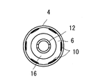
図1において、4はトルクリミッター2の外側回転体(ハウジング)であり、これの内径部にキャップ6と、半硬質磁性体(ヒステリシスリング)8が固定されている。
Embodiments of the present invention will be described below in detail with reference to the accompanying drawings.
In FIG. 1,
前記キャップ6には、軸方向の全長にわたって伸びる複数の溝10が形成されている。本件発明の対象となっている永久磁石と半硬質磁性体とによるトルクリミッターにおいては、対向配置された永久磁石が半硬質磁性体を磁化し、その磁気ヒステリシスループの面積に比例する回転力を伝達する(ヒステリシストルク)。そして最大伝達トルクを超えたときには、永久磁石と半硬質磁性体とが一定のトルクを維持した状態で相対回転し、そのときに半硬質磁性体が発熱し、外側回転体4(ハウジング)内の温度が上昇する。この温度上昇が、永久磁石のもつ温度係数分だけ永久磁石を減磁させ、その結果、トルクリミッターの伝達トルクが低下してしまうことになる。上記キャップ6に形成された溝10は、外側回転体4の内周面とキャップ6との間に形成されており、外側回転体4内の熱を外部に放出するための空気抜き穴10として機能し、外側回転体4内の温度上昇による磁力低下を抑制している。
The
12は、内側回転体(スリーブ)であり、両端部の近傍が軸受け14,16によって前記外側回転体4の内径部に回転自在に支持されている。前記内側回転体12の外周面に管状の永久磁石18が嵌挿され、該永久磁石18の外周面は、所定の隙間を存して前記半硬質磁性体8の内周面と対向している。
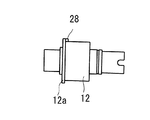
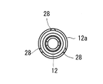
前記永久磁石18の一端面には、図7に示すように、凹部26が形成され、この凹部26に対応して、内側回転体12のつば部12aには凸部28が形成されている。上記凹部26と凸部28は、回転方向と軸方向に係合する突き当て面26,28を構成している。前記突き当て面26,28は、互いに嵌合し、これによって、前記内側回転体12と永久磁石18との回転方向の相対移動を規制する回転方向移動制限手段を構成している。
As shown in FIG. 7, a
この回転方向移動制限手段は、正逆2方向の回転方向の移動を制限するが、外側回転体4と内側回転体12との相対回転方向が一方向のみであるものにおいては、その相対回転方向1方向のみの回転を制限する構成であっても良い。前記内側回転体12には、リテーナ20が固定され、該リテーナ20の外周面にOリングからなる弾性材料22が嵌挿されている。
This rotational direction movement restricting means restricts the movement in the forward and reverse two rotational directions, but when the relative rotational direction of the
前記弾性材料22は、リテーナ20のつば部20aに係止され、前記永久磁石18の端部とリテーナ20に圧接している。前記弾性材料22の弾力により前記永久磁石18と内側回転体12は、軸方向と径方向即ち軸方向に対して垂直な方向に押圧され、この押圧力により、永久磁石18は、ガタのない状態で、弾性材料22を介して内側回転体12に固定されている。ここに、弾性材料22は、内側回転体12と永久磁石18との両者を径方向に押圧する押圧手段を構成する。
The
前記弾性材料22による、軸方向の押圧力により、永久磁石18の端面に形成された突き当て面26は、内側回転体12のつば部12aの突き当て面28に当接し、永久磁石18の内側回転体12に対する軸方向の移動が係止される。本実施形態において、突き当て面26,28と、該突き当て面26,28同士が当接するように永久磁石18をリテーナ20を支点として軸方向に付勢する弾性材料22は、内側回転体12と永久磁石18との軸方向の相対移動を規制する軸方向移動制限手段を構成している。
Due to the pressing force of the
上記のように構成したトルクリミッター2は、永久磁石18と半硬質磁性体8との間に生じるヒステリシストルクにより、内側回転体12と外側回転体4との相対回転が規制されているが、内側回転体12若しくは外側回転体4に入力される回転トルクが、ヒステリシストルクによって規制されたトルク以上になると、内側回転体12と外側回転体4とが相対回転する。
In the
つまり、入力される回転トルクが小さければ、内側回転体12若しくは外側回転体4の回転を、外側回転体4もしくは内側回転体12に伝達するが、入力される回転トルクが所定の大きさを超えると、内側回転体12と外側回転体4とが相対回転し、過大な負荷が外側回転体4若しくは内側回転体12に作用しないようにしている。
That is, if the input rotational torque is small, the rotation of the inner rotating
上記第1の実施形態では、永久磁石18の一端側にのみ弾性材料22を配置したが、図8に示すように、永久磁石18の両端にOリングからなる弾性材料24,22を配置し、弾性材料24を内側回転体12のつば部12bで係止するとともに、弾性材料22をリテーナ20で係止し、永久磁石18の両端を弾性材料24,22によって弾発し、永久磁石18と内側回転体12とを径方向及び軸方向に押圧する構成としても良い。この場合、弾性材料24,22は、内側回転体12と永久磁石18との両者を径方向に押圧する押圧手段であると同時に、両者の軸方向の相対移動を規制する軸方向移動制限手段である。
In the first embodiment, the
また、上記実施形態ではいずれも、永久磁石18と内側回転体12とを、弾性材料22,24により、径方向と軸方向の両方に押圧しているが、図9に示すように、リテーナ20のつば部20aと内側回転体12の端面12c間に係止した弾性材料22を、リテーナ20を支点として永久磁石18の内周面に、これに対して垂直に圧接し、永久磁石18と内側回転体12とを、弾性材料22の弾力によって、径方向のみに押圧するようにしても良い。この場合、弾性材料22は、内側回転体12と永久磁石18との両者を径方向に押圧する押圧手段を構成する。
In the above embodiments, the
図9中、リテーナ20のつば部20aは、永久磁石18の端面と当接し、永久磁石18が内側回転体12に対して軸方向にずれないように永久磁石18を係止している。本実施形態において、リテーナ20のつば部20aと内側回転体12のつば部12aの突き当て面28と永久磁石18に設けられた突き当て面26とは、内側回転体と永久磁石との軸方向の相対移動を規制する軸方向移動制限手段を構成している。
In FIG. 9, the
また図10に示すように、弾性材料22を、内側回転体12の段部12eの外周面と永久磁石18の内周面との間に圧縮配置し、永久磁石18と内側回転体12とを径方向に押圧する構成としても良い。図10において、弾性材料22は、内側回転体12の段部12eの壁面12dとリテーナ20のつば部20bとの間で係止され、且つ、リテーナ20のつば部20bは、永久磁石18の端面に当接してこれを内側回転体12に対して軸方向にずれないように係止している。
Further, as shown in FIG. 10, the
上記実施形態はいずれも、弾性材料としてOリングを用いているが、本発明の実施に際しては特にOリングに限定されるものではなく、図11及び図12に示すように、内側回転体12の外周面に、その軸方向に沿って複数の条溝30を設け、各条溝30に棒状の弾性材料32を配置し、該弾性材料32を永久磁石18の内周面に圧接するようにしても良い。
In any of the above embodiments, an O-ring is used as the elastic material. However, the present invention is not particularly limited to the O-ring, and as shown in FIGS. A plurality of
図11に示す実施形態の他の構成は、図1に示す実施形態と略同一である。また、本発明は、外側回転体に半硬質磁性体を組み込み、内側回転体に永久磁石を組み込んだ構成に特に限定されるものではなく、その逆、即ち、外側回転体に永久磁石を組み込み、内側回転体に半硬質磁性体を組み込んだ構成としても良い。 Other configurations of the embodiment shown in FIG. 11 are substantially the same as those of the embodiment shown in FIG. Further, the present invention is not particularly limited to a configuration in which a semi-rigid magnetic body is incorporated in the outer rotating body and a permanent magnet is incorporated in the inner rotating body, and vice versa, that is, a permanent magnet is incorporated in the outer rotating body, It is good also as a structure which incorporated the semi-hard magnetic body in the inner side rotary body.
2 トルクリミッター
4 外側回転体
6 キャップ
8 半硬質磁性体
10 空気穴
12 内側回転体
14 軸受け
16 軸受け
18 永久磁石
20 リテーナ
22 弾性材料
24 弾性材料
26 突き当て面
28 突き当て面
30 条溝
32 弾性材料
2
Claims (3)
An inner rotating body is incorporated into the outer rotating body so as to be relatively rotatable, and a permanent magnet is incorporated into one of the outer rotating body and the inner rotating body, and the other rotating body is opposed to the permanent magnet. In the torque limiter incorporating the semi-rigid magnetic body, the means for incorporating the permanent magnet into the rotating body includes an elastic material interposed between the rotating body and the permanent magnet, and the elastic material causes the both to at least radially. A first abutting surface in the rotational direction is formed on one side of the pressing means for pressing, the rotating body and the permanent magnet, and the other side is opposed to the first abutting surface in the rotational direction. A rotation direction movement control that forms a second abutting surface and restricts relative movement of the rotating body and the permanent magnet in the rotation direction by contacting the first abutting surface and the second abutting surface. It means a torque limiter, characterized in that it consists axial movement restricting means for restricting relative axial movement between the rotating body and the permanent magnet.
Priority Applications (2)
| Application Number | Priority Date | Filing Date | Title |
|---|---|---|---|
| JP2005069497A JP2006250283A (en) | 2005-03-11 | 2005-03-11 | Torque limiter |
| CNB2006100012875A CN100480156C (en) | 2005-03-11 | 2006-01-12 | Torque limiter |
Applications Claiming Priority (1)
| Application Number | Priority Date | Filing Date | Title |
|---|---|---|---|
| JP2005069497A JP2006250283A (en) | 2005-03-11 | 2005-03-11 | Torque limiter |
Publications (2)
| Publication Number | Publication Date |
|---|---|
| JP2006250283A true JP2006250283A (en) | 2006-09-21 |
| JP2006250283A5 JP2006250283A5 (en) | 2007-12-06 |
Family
ID=36993813
Family Applications (1)
| Application Number | Title | Priority Date | Filing Date |
|---|---|---|---|
| JP2005069497A Pending JP2006250283A (en) | 2005-03-11 | 2005-03-11 | Torque limiter |
Country Status (2)
| Country | Link |
|---|---|
| JP (1) | JP2006250283A (en) |
| CN (1) | CN100480156C (en) |
Cited By (2)
| Publication number | Priority date | Publication date | Assignee | Title |
|---|---|---|---|---|
| JP2008256119A (en) * | 2007-04-05 | 2008-10-23 | Tsubakimoto Chain Co | Cylindrical magnetic gear |
| JP2011106559A (en) * | 2009-11-17 | 2011-06-02 | Yamauchi Corp | Torque limiter |
Families Citing this family (2)
| Publication number | Priority date | Publication date | Assignee | Title |
|---|---|---|---|---|
| JP2011182939A (en) * | 2010-03-08 | 2011-09-22 | Fujifilm Corp | Conduit connection device for medical device |
| FR3022526B1 (en) * | 2014-06-20 | 2016-06-24 | Sagem Defense Securite | ELECTROMECHANICAL ACTUATOR WITH MAGNETIC TORQUE LIMITER |
Citations (3)
| Publication number | Priority date | Publication date | Assignee | Title |
|---|---|---|---|---|
| JPH0671915U (en) * | 1993-03-22 | 1994-10-07 | 光洋精工株式会社 | Bearing device |
| JPH0829720A (en) * | 1994-07-20 | 1996-02-02 | Fuji Xerox Co Ltd | Mounting structure for rotary polygon mirror |
| JP2001208094A (en) * | 2000-01-27 | 2001-08-03 | Yamauchi Corp | Co-axial cylindrical torque limiter and its process of manufacture |
-
2005
- 2005-03-11 JP JP2005069497A patent/JP2006250283A/en active Pending
-
2006
- 2006-01-12 CN CNB2006100012875A patent/CN100480156C/en not_active Expired - Fee Related
Patent Citations (3)
| Publication number | Priority date | Publication date | Assignee | Title |
|---|---|---|---|---|
| JPH0671915U (en) * | 1993-03-22 | 1994-10-07 | 光洋精工株式会社 | Bearing device |
| JPH0829720A (en) * | 1994-07-20 | 1996-02-02 | Fuji Xerox Co Ltd | Mounting structure for rotary polygon mirror |
| JP2001208094A (en) * | 2000-01-27 | 2001-08-03 | Yamauchi Corp | Co-axial cylindrical torque limiter and its process of manufacture |
Cited By (2)
| Publication number | Priority date | Publication date | Assignee | Title |
|---|---|---|---|---|
| JP2008256119A (en) * | 2007-04-05 | 2008-10-23 | Tsubakimoto Chain Co | Cylindrical magnetic gear |
| JP2011106559A (en) * | 2009-11-17 | 2011-06-02 | Yamauchi Corp | Torque limiter |
Also Published As
| Publication number | Publication date |
|---|---|
| CN100480156C (en) | 2009-04-22 |
| CN1831354A (en) | 2006-09-13 |
Similar Documents
| Publication | Publication Date | Title |
|---|---|---|
| JP5351377B2 (en) | Force limiting assembly | |
| JP2006250283A (en) | Torque limiter | |
| JP2009156283A (en) | Rotation transmitting device | |
| JP2006312954A (en) | Torque limiter | |
| JP2009287579A (en) | Torque transmission mechanism | |
| JP2009083699A (en) | Wheel support device | |
| JP2014152799A (en) | Double roller type tripod-shaped constant velocity joint | |
| JP5026301B2 (en) | Rolling bearing unit and manufacturing method thereof | |
| JP2006118586A (en) | Power transmission device | |
| JP6576767B2 (en) | Reverse input blocking device | |
| JP2007270966A (en) | Creep prevention structure of rolling bearing | |
| JP4827401B2 (en) | Torque limiter and manufacturing method thereof | |
| JP2007113751A (en) | Power transmission structure of motor | |
| JP2009210025A (en) | Reverse input preventing clutch | |
| JP2005163868A (en) | Bearing device | |
| JP2005337270A (en) | Torque limiter | |
| JP2005344858A (en) | Torque limiter | |
| JP4432815B2 (en) | Power transmission device | |
| JP2009185860A (en) | Rolling bearing unit | |
| JP2003090359A (en) | One-way clutch | |
| JP4391322B2 (en) | Universal joint | |
| JP2013002465A (en) | Rolling bearing mounting structure in rotating shaft device | |
| JP2010175024A (en) | Bearing for steering column | |
| JP4761208B2 (en) | Bearing device | |
| JP4864640B2 (en) | Torque limiter |
Legal Events
| Date | Code | Title | Description |
|---|---|---|---|
| A621 | Written request for application examination |
Free format text: JAPANESE INTERMEDIATE CODE: A621 Effective date: 20070808 |
|
| A521 | Written amendment |
Effective date: 20071001 Free format text: JAPANESE INTERMEDIATE CODE: A523 |
|
| A521 | Written amendment |
Effective date: 20071018 Free format text: JAPANESE INTERMEDIATE CODE: A523 |
|
| A977 | Report on retrieval |
Free format text: JAPANESE INTERMEDIATE CODE: A971007 Effective date: 20090619 |
|
| A131 | Notification of reasons for refusal |
Free format text: JAPANESE INTERMEDIATE CODE: A131 Effective date: 20090623 |
|
| A521 | Written amendment |
Free format text: JAPANESE INTERMEDIATE CODE: A523 Effective date: 20090817 |
|
| A131 | Notification of reasons for refusal |
Effective date: 20100106 Free format text: JAPANESE INTERMEDIATE CODE: A131 |
|
| A521 | Written amendment |
Effective date: 20100120 Free format text: JAPANESE INTERMEDIATE CODE: A523 |
|
| A02 | Decision of refusal |
Effective date: 20100723 Free format text: JAPANESE INTERMEDIATE CODE: A02 |