JP2006247268A - System and method for positioning patient - Google Patents
System and method for positioning patient Download PDFInfo
- Publication number
- JP2006247268A JP2006247268A JP2005071291A JP2005071291A JP2006247268A JP 2006247268 A JP2006247268 A JP 2006247268A JP 2005071291 A JP2005071291 A JP 2005071291A JP 2005071291 A JP2005071291 A JP 2005071291A JP 2006247268 A JP2006247268 A JP 2006247268A
- Authority
- JP
- Japan
- Prior art keywords
- area
- image information
- patient
- positioning
- image
- Prior art date
- Legal status (The legal status is an assumption and is not a legal conclusion. Google has not performed a legal analysis and makes no representation as to the accuracy of the status listed.)
- Pending
Links
Images


Classifications
-
- A—HUMAN NECESSITIES
- A61—MEDICAL OR VETERINARY SCIENCE; HYGIENE
- A61B—DIAGNOSIS; SURGERY; IDENTIFICATION
- A61B6/00—Apparatus for radiation diagnosis, e.g. combined with radiation therapy equipment
- A61B6/46—Apparatus for radiation diagnosis, e.g. combined with radiation therapy equipment with special arrangements for interfacing with the operator or the patient
- A61B6/461—Displaying means of special interest
- A61B6/463—Displaying means of special interest characterised by displaying multiple images or images and diagnostic data on one display
-
- A—HUMAN NECESSITIES
- A61—MEDICAL OR VETERINARY SCIENCE; HYGIENE
- A61B—DIAGNOSIS; SURGERY; IDENTIFICATION
- A61B6/00—Apparatus for radiation diagnosis, e.g. combined with radiation therapy equipment
- A61B6/04—Positioning of patients; Tiltable beds or the like
-
- A—HUMAN NECESSITIES
- A61—MEDICAL OR VETERINARY SCIENCE; HYGIENE
- A61B—DIAGNOSIS; SURGERY; IDENTIFICATION
- A61B6/00—Apparatus for radiation diagnosis, e.g. combined with radiation therapy equipment
- A61B6/54—Control of apparatus or devices for radiation diagnosis
- A61B6/545—Control of apparatus or devices for radiation diagnosis involving automatic set-up of acquisition parameters
-
- A—HUMAN NECESSITIES
- A61—MEDICAL OR VETERINARY SCIENCE; HYGIENE
- A61N—ELECTROTHERAPY; MAGNETOTHERAPY; RADIATION THERAPY; ULTRASOUND THERAPY
- A61N5/00—Radiation therapy
- A61N5/10—X-ray therapy; Gamma-ray therapy; Particle-irradiation therapy
- A61N5/1048—Monitoring, verifying, controlling systems and methods
- A61N5/1049—Monitoring, verifying, controlling systems and methods for verifying the position of the patient with respect to the radiation beam
- A61N2005/1061—Monitoring, verifying, controlling systems and methods for verifying the position of the patient with respect to the radiation beam using an x-ray imaging system having a separate imaging source
Abstract
Description
本発明は、X線又は陽子線をはじめとする粒子線等の各種放射線を患部に照射して治療する放射線治療に用いる患者位置決めシステム及び患者位置決め方法に関する。 The present invention relates to a patient positioning system and a patient positioning method used for radiation therapy in which an affected area is irradiated with various types of radiation such as X-rays or proton beams.
腫瘍細胞を、各種放射線を照射することで壊死させることを目的とする放射線治療は、近年広く行われつつある。用いられる放射線としては最も広く利用されているX線だけでなく、陽子線をはじめとする粒子線を使った治療も行われている。 In recent years, radiotherapy aimed at necrosis of tumor cells by irradiating various types of radiation has been widely performed. As the radiation used, treatment using not only the most widely used X-ray but also a particle beam such as a proton beam is performed.
放射線治療の重要なプロセスの一つに患者の位置決めがある。患者の位置決めとは、一般に治療計画装置から出力されたDRR(Digital Reconstructed Radiograph)画像と放射線照射前にX線透視装置を用いて治療台の上に患者を寝かせた状態で撮影するDR(Digital Radiograph)画像とを技師または医師が比較することにより、治療計画で決定した患者の位置と現在の治療台上の患者の位置とのズレを算出し、二種類の画像が一致するように治療台の移動量を求め、治療台を移動させるプロセスである。 One important process of radiation therapy is patient positioning. The patient positioning is generally a DRR (Digital Reconstructed Radiograph) image output from the treatment planning device and a DR (Digital Radiograph) imaged with the patient lying on the treatment table using an X-ray fluoroscopy device before irradiation. ) By comparing the images with the technician or doctor, the difference between the patient position determined in the treatment plan and the patient position on the current treatment table is calculated, and the treatment table position is adjusted so that the two images match. This is a process of determining the amount of movement and moving the treatment table.
DRR画像は、DR画像を模擬した画像であり、治療計画時に撮影されたCT画像から生成される。以下、適宜、DRR画像のことを参照画像、またDR画像のことを比較画像と呼ぶ。なお、患者位置決めでは、参照画像として上記DRR画像の代わりにX線シミュレータ等を用いて撮影した画像を用いる場合もある。 The DRR image is an image simulating a DR image and is generated from a CT image taken at the time of treatment planning. Hereinafter, the DRR image is appropriately referred to as a reference image, and the DR image is referred to as a comparative image. In patient positioning, an image captured using an X-ray simulator or the like may be used as a reference image instead of the DRR image.
現在の患者の位置と治療計画時の位置とのズレを算出する方式として、従来、参照点(計算点)入力方式が用いられている。これは、コンピュータのモニタ上に参照画像と比較画像とを表示し、移動量を算出するために、システムの操作者が両画像の対応する点(例えば骨の部分などの明確に識別できる箇所が選ばれる。指定される点は参照点と呼ばれる。)をマウス等の入力手段を用いて指定し、対応する点の誤差が最小になるように移動量を求める方式である(例えば、特許文献1参照。)。 Conventionally, a reference point (calculation point) input method has been used as a method for calculating the difference between the current patient position and the position at the time of treatment planning. This is because a reference image and a comparative image are displayed on a computer monitor, and a point where the operator of the system can clearly identify a point corresponding to both images (for example, a bone portion or the like) is calculated in order to calculate the movement amount. This is a method in which a designated point is called a reference point) using an input means such as a mouse, and the amount of movement is calculated so that the error of the corresponding point is minimized (for example, Patent Document 1). reference.).
また、参照画像と比較画像の両画像の画素値を比較し、相関係数や差の二乗等が最小になるように移動量を求める画像比較方式も用いられている(例えば、特許文献2参照。)。 In addition, an image comparison method is also used in which pixel values of both the reference image and the comparison image are compared to obtain a movement amount so that the correlation coefficient, the square of the difference, or the like is minimized (see, for example, Patent Document 2). .)
近年、画像技術の高度化によりDR画像についても高解像度化且つ大サイズ化する傾向にあり、例えば2048×2048ピクセル程度のDR画像がX線撮像装置から出力される。このような大サイズの画像を通常のモニタ(例えば、1280×1024ピクセルの解像度のモニタ)に全体表示する場合、100%の大きさ(すなわち縮小なし)で画像全体を表示することはできず、上記の例では2048×2048ピクセルの画像を1280×1024の解像度のモニタに表示するのであるから、最大50%に縮小した画像を表示することになる。 In recent years, with the advancement of image technology, DR images tend to have higher resolution and larger size. For example, a DR image of about 2048 × 2048 pixels is output from an X-ray imaging apparatus. When displaying such a large image on a normal monitor (for example, a monitor having a resolution of 1280 × 1024 pixels), the entire image cannot be displayed in a size of 100% (that is, no reduction) In the above example, since an image of 2048 × 2048 pixels is displayed on a monitor having a resolution of 1280 × 1024, an image reduced to a maximum of 50% is displayed.
ここで、上記従来の参照点入力方式において、操作者が通常のモニタを用いてDR画像全体を俯瞰しつつ参照点を入力しようとする場合、上述したように縮小画像に対して参照点を入力することになる。その結果、仮に100%の画像が表示されていた場合には1ピクセルの特定の点を指定できるのに対し、上記の例で言えば画像が高さ及び幅ともに50%に縮小されているので、4ピクセルを一度に選択することになる。さらに、実際の画像表示ソフトウェアではグラフィカルユーザインタフェースのボタンやスクロールバー、メニュー等が画面上に存在するため、画像の表示倍率はさらに小さくなり、一度に選択されるピクセル数はさらに増加する可能性がある。このため、操作者が意図する参照点と対応する画像上の点との対応が曖昧になり、意図した点とは違う画像上の点が参照点となって位置決めの精度が悪化するおそれがあった。 Here, in the above-described conventional reference point input method, when the operator intends to input a reference point while looking down on the entire DR image using a normal monitor, the reference point is input to the reduced image as described above. Will do. As a result, if a 100% image is displayed, a specific point of one pixel can be specified, whereas in the above example, the image is reduced to 50% in both height and width. Four pixels will be selected at a time. In addition, since the actual image display software has buttons, scroll bars, menus, etc. on the screen on the screen, the image display magnification is further reduced, and the number of pixels selected at one time may be further increased. is there. For this reason, the correspondence between the reference point intended by the operator and the corresponding point on the image becomes ambiguous, and a point on the image different from the intended point may become a reference point, which may deteriorate the positioning accuracy. It was.
一方、上記従来の画像比較方式では、表示の倍率にかかわり無く演算を実施するため、上記のような参照点の曖昧さに起因する位置決め精度低下の問題は発生しない。しかしながら、比較対照となる画像領域全体の画素値を比較する方式のため、参照点入力方式と比較すると計算量が多く、位置決め時間が長くなる問題点があった。 On the other hand, in the conventional image comparison method, since the calculation is performed regardless of the display magnification, the above-described problem of deterioration in positioning accuracy due to the ambiguity of the reference point does not occur. However, this method involves comparing pixel values of the entire image area to be compared, so that there is a problem that the calculation amount is large and the positioning time is long compared with the reference point input method.
以上のように、上記従来の参照点入力方式及び画像比較方式では、位置決め精度の向上と位置決め時間の短縮とを両立させることができなかった。 As described above, in the conventional reference point input method and image comparison method, it is impossible to achieve both improvement in positioning accuracy and reduction in positioning time.
本発明は、上記従来技術の課題を解決するために考え出されたものであり、その目的は、位置決め精度の向上と位置決め時間の短縮とを両立できる患者位置決めシステム及び患者位置決め方法を提供することにある。 The present invention has been conceived in order to solve the above-described problems of the prior art, and an object of the present invention is to provide a patient positioning system and a patient positioning method capable of both improving positioning accuracy and shortening positioning time. It is in.
上記した目的を達成する本発明の特徴は、前記患者の患部領域を含む画像情報である第1画像情報及び第2画像情報の少なくとも1つを縮小表示可能な表示装置と、前記表示装置に表示された前記第1画像情報及び前記第2画像情報における特定の領域を指定入力する入力装置と、前記指定入力された特定領域を前記表示装置の縮小倍率に応じて拡大した拡大領域を設定する拡大領域設定処理装置と、前記設定された拡大領域中にその一部領域である代表領域を設定する代表領域設定処理装置と、前記第1画像情報中の代表領域の位置情報と、前記第2画像情報中の代表領域の位置情報とに基づき、前記患者の位置決めに用いる位置決め情報を生成する演算処理装置とを備えることにある。表示装置の縮小倍率に応じて特定領域を拡大し、その拡大領域中に代表領域を設定した上で、対応する代表領域の位置ずれが最小になるように位置決め情報を生成することにより、縮小表示した状態で特定領域(参照点)の指定入力を行った場合でも位置決め精度低下の問題が生じることはない。また、画像比較方式のように画像全体の画素値を比較する方式ではないため、計算量が少なく、位置決め時間も短くて済む。したがって、位置決め精度の向上と位置決め時間の短縮とを両立させることができる。 A feature of the present invention that achieves the above-described object is that a display device capable of reducing and displaying at least one of first image information and second image information, which is image information including the affected area of the patient, is displayed on the display device. An input device for designating and inputting a specific area in the first image information and the second image information, and an enlargement for setting an enlarged area in which the designated and input specific area is enlarged in accordance with a reduction magnification of the display device A region setting processing device; a representative region setting processing device for setting a representative region which is a partial region in the set enlarged region; position information of a representative region in the first image information; and the second image. And an arithmetic processing unit that generates positioning information used for positioning of the patient based on position information of the representative region in the information. A specific area is enlarged according to the reduction magnification of the display device, a representative area is set in the enlarged area, and positioning information is generated so as to minimize the displacement of the corresponding representative area, thereby reducing the display. Even if a specific area (reference point) is designated and input in the state where it has been performed, the problem of a decrease in positioning accuracy does not occur. Further, since it is not a method for comparing pixel values of the entire image as in the image comparison method, the calculation amount is small and the positioning time is short. Therefore, both improvement in positioning accuracy and shortening of the positioning time can be achieved.
本発明によれば、位置決め精度の向上と位置決め時間の短縮とを両立できる。 According to the present invention, it is possible to improve both positioning accuracy and shorten positioning time.
以下、本発明の実施形態を図面を参照しつつ説明する。 Embodiments of the present invention will be described below with reference to the drawings.
(実施形態1)
図1は、本発明の好適な一実施形態である患者位置決めシステムの全体構成図である。
(Embodiment 1)
FIG. 1 is an overall configuration diagram of a patient positioning system according to a preferred embodiment of the present invention.
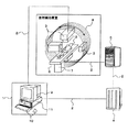
この図1に示すように、本実施形態の患者位置決めシステムは、回転ガントリを備えた放射線(例えば陽子線)治療装置に用いられるものを想定している。なお、本発明はこれ以外にもX線治療装置等の一般的な放射線治療装置に適用可能である。 As shown in FIG. 1, the patient positioning system of the present embodiment is assumed to be used for a radiation (for example, proton beam) treatment apparatus having a rotating gantry. In addition, the present invention can be applied to a general radiotherapy apparatus such as an X-ray therapy apparatus.
図1において、患者位置決め用コンピュータ1は、ネットワークケーブル2を介し、X線透視画像撮影装置3、医用画像サーバ(画像情報格納装置)4、及び治療台制御装置5と接続されている。治療台制御装置5は、患者が治療照射時に横臥するベッド(治療台)6を駆動するベッド駆動装置7の制御を行い、ベッド6の位置を制御する。またX線透視画像撮影装置3は、治療照射前にベッド6上に患者12を寝かせた状態で患者12の患部領域を撮影するためのものであり、回転ガントリ8内において患者12の近傍に配置され、回転ガントリ8の回転に伴い患者12の周囲を回転可能に設置されている。このX線透視画像撮影装置3により撮影された患者12の患部領域を含む画像データ(第2画像情報)は、ネットワークケーブル2を介して比較画像(DR(Digital Radiograph)画像)として患者位置決め用コンピュータ1に出力される。一方、治療計画時に作成されたCT画像(立体画像)及びこのCT画像から生成された適宜の断層画像である参照画像(DRR(Digital Reconstructed Radiograph)画像)は医用画像サーバ4に格納されており、必要に応じて患者位置決め用コンピュータ1によって取得される。この患者位置決め用コンピュータ1は、X線透視画像撮影装置3から取得した比較画像と医用画像サーバ4から取得した参照画像とを表示するモニタ(表示装置)9、コンピュータ操作者が各種入力操作をするためのマウスやキーボード等の入力装置10、及び演算装置(拡大領域設定処理装置、代表領域設定処理装置、演算処理装置)11を備えている。
In FIG. 1, a patient positioning computer 1 is connected to an X-ray fluoroscopic image capturing
なお、上記では、X線透視画像撮影装置3から患者位置決め用コンピュータ1に直接比較画像が送信されるように記載したが、X線透視画像撮影装置3から医用画像サーバ4に送信されて画像データが一旦保管され、保管された画像データが患者位置決め用コンピュータ1により比較画像として読み出されるようにしてもよい。
In the above description, the comparison image is directly transmitted from the X-ray fluoroscopic
図2は患者位置決め用コンピュータ1の演算装置11により行われる制御フローである。以下、この図2を用いて、本実施形態の患者位置決めシステムにより行われる患者12の位置決め手順について説明する。なお、このフローは操作者からの適宜の位置決め開始指示(例えば入力装置10からの指示入力)があった際に開始される。
FIG. 2 is a control flow performed by the
まず、治療計画時に作成され医用画像サーバ4に格納されている参照画像を、例えば図示しない記憶装置(メモリ)等に読み込む(ステップ21)。
First, a reference image created at the time of treatment planning and stored in the
次に、X線透視画像撮影装置3により撮影されたベッド6上に寝ている状態の患者12の比較画像を、X線透視画像撮影装置3から例えば図示しない記憶装置(メモリ)等に読み込む(ステップ22)。なお、この比較画像は、X線透視画像撮影装置3(又は患者位置決め用コンピュータ1でもよい)から医用画像サーバ4にも送信され、サーバ4内に保管される。
Next, a comparison image of the
なお、上記のステップ21とステップ22は、順序が入れ替わってもよいし、並列して行ってもよい。
In addition, said
上記ステップ21及びステップ22において参照画像及び比較画像の両画像の読込みが終了すると、患者位置決め用コンピュータ1のモニタ9に両画像を表示する(ステップ23)。この時、モニタ9の画像表示部分に参照画像と比較画像の両画像全体が表示部分に収まるように、必要に応じて縮小して表示する。本実施形態では、例えば、参照画像及び比較画像のサイズは共に2048×2048ピクセルの画像であり(図3(B)参照)、患者位置決め用コンピュータ1のモニタ9におけるそれぞれの画像の画像表示領域のサイズは512×512ピクセルであるとする。したがって、参照画像及び比較画像は共に25%に縮小されて表示される(図3(A)参照)。なお、図3には参照画像及び比較画像のうちの一方のみを図示している。
When the reading of both the reference image and the comparison image is completed in
次に、操作者により参照点(特定領域)が入力されたかどうかが判定される(ステップ24)。具体的には、参照画像及び比較画像の両画像全体が25%に縮小表示された状態のモニタ9の画面上で、操作者が入力装置10を用いて参照画像と比較画像のそれぞれの対応する位置に患者位置決めに使用する参照点を入力したかどうかが判定される。なお、この参照点は、画像上において一部分に偏よらずに全体的に分散されて配置されるのが好ましいため、通常、このように患部領域全体を表示させながら操作者により入力される。参照点の入力位置としては、例えば骨の先端部分などの明確に識別できる箇所が選ばれる。
Next, it is determined whether or not a reference point (specific area) has been input by the operator (step 24). Specifically, on the screen of the monitor 9 in a state where both the reference image and the comparison image are reduced and displayed at 25%, the operator uses the
図3(A)に4箇所の参照点を入力した例を示す。この図3(A)に示すように、参照点は点で表示されている。 FIG. 3A shows an example in which four reference points are input. As shown in FIG. 3A, the reference points are displayed as dots.
次に、操作者により画像の拡大指示入力があったかどうかが判定される(ステップ25)。具体的には、操作者が入力装置10を用いてモニタ9に表示されている画像を拡大する指示入力を行ったかどうかが判定される。拡大指示入力があった場合、点であった参照点を拡大して計算領域(拡大領域)として例えば矩形の線画で表示する(ステップ26)。この状態を図3(B)に示す。この図3(B)は、2048×2048ピクセルの画像が100%表示された状態である(なお、実際にはモニタ9には100%表示の状態では画像全体の1/4しか表示されない)。この計算領域は、図4に示すように1辺が4ピクセルである16ピクセルの矩形領域で構成される。すなわち、図3(A)に示す縮小表示画面上では1ピクセルで構成された参照点が、モニタ9の画像表示を拡大すると図3(B)に示すようにその拡大倍率(言い換えると縮小倍率)に応じて拡大され、4×4ピクセルの計算領域として設定される。
Next, it is determined whether or not an operator has input an image enlargement instruction (step 25). Specifically, it is determined whether or not the operator has input an instruction to enlarge the image displayed on the monitor 9 using the
さらに、操作者により上記設定された計算領域の修正がされたかどうかを判定する(ステップ27)。本実施形態では、操作者は、計算領域の修正操作として、領域の伸縮、移動、回転等が可能である。操作者により入力装置10を用いて修正入力がされると、修正された計算領域は即座に反映される(ステップ28)。なお、ここでは本計算領域を矩形形状としたが、必ずしも矩形である必要はなく、円形や楕円形等の任意の形状で定義可能である。
Further, it is determined whether or not the operator has corrected the set calculation area (step 27). In the present embodiment, the operator can expand / contract, move, rotate, etc. the area as a calculation area correction operation. When the operator makes correction input using the
このようにして計算領域が確定すると、その計算領域中に代表点(代表領域)を設定する。この代表点の算出手法について、図5及び図6を用いて以下に説明する。 When the calculation area is thus determined, a representative point (representative area) is set in the calculation area. This representative point calculation method will be described below with reference to FIGS.
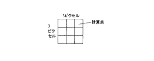
説明を簡易とするために、図5では計算領域を1辺が3ピクセルである9ピクセルの矩形領域で構成した場合を考える。これは、参照画像及び比較画像が33%の縮小倍率でモニタ9に表示されている状態で操作者が参照点を入力し、100%表示に拡大した状態に相当する。 In order to simplify the explanation, consider the case where the calculation area is composed of a rectangular area of 9 pixels with 3 pixels on one side in FIG. This corresponds to a state in which the operator inputs a reference point while the reference image and the comparative image are displayed on the monitor 9 at a reduction ratio of 33% and is enlarged to 100% display.
本実施形態では、この計算領域に含まれる各ピクセルを計算点とし、計算領域を9点の計算点の集合であると考える。そして、各計算点に対し重み付けを行い、その重みを考慮して計算領域内に含まれる計算点から一つの代表点を算出する。この代表点を算出するための重みとしては、計算領域内の画素値を使用する。これは、一般にX線透視画像を用いた患者の位置決めでは、骨のような明確な構造物を位置決めのための計算点とすることが多く、X線透視画像上では骨のような明確な構造物は輝度(すなわち画素値)が高くなり、画素値の大きさが骨等の明確な構造物を表す指標であると考えられるからである。 In this embodiment, each pixel included in the calculation area is regarded as a calculation point, and the calculation area is considered to be a set of nine calculation points. Each calculation point is weighted, and one representative point is calculated from the calculation points included in the calculation region in consideration of the weight. As a weight for calculating the representative point, a pixel value in the calculation area is used. In general, in positioning of a patient using a fluoroscopic image, a clear structure such as a bone is often used as a calculation point for positioning. On the fluoroscopic image, a clear structure such as a bone is often used. This is because an object has high luminance (that is, a pixel value), and the size of the pixel value is considered to be an index representing a clear structure such as a bone.
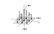
具体的には、計算領域内で画素値が最大である計算点の重みを1とし、その他の計算点の画素値を最大の画素値で規格化し重み付けする。そして、各計算点の重みを当該計算点の座標に掛け合わせ、得られた結果を足し算することで代表点を算出する。なお、このときに用いられる各計算点の座標は、計算領域内の中心を原点としたものである。このように計算領域内の画素値を重みに変換し、その重み分布を考慮して代表点を算出することにより、操作者が入力したかった点を再現することができるようになっている。なお、上記重み分布は、入力情報の確実性を表す確率分布であるとも言うことができる(すなわち、重みが1である画素値が最大の点が、操作者が入力した点である確率が最も高いことになる)。 Specifically, the weight of the calculation point having the maximum pixel value in the calculation area is set to 1, and the pixel values of other calculation points are normalized and weighted with the maximum pixel value. Then, the representative point is calculated by multiplying the weight of each calculation point by the coordinates of the calculation point and adding the obtained results. Note that the coordinates of each calculation point used at this time are based on the origin in the calculation area. In this way, by converting the pixel values in the calculation area into weights and calculating the representative points in consideration of the weight distribution, it is possible to reproduce the points that the operator wanted to input. The weight distribution can also be said to be a probability distribution representing the certainty of the input information (that is, the probability that the pixel value with the weight of 1 is the highest is the point input by the operator). Will be expensive).
図6は図5に示す計算領域に重み付けを行ったときの重み分布の一例を示す図である。この図6に示す分布は、計算領域の中央のピクセルが最も大きな画素値であり、この中央のピクセルに垂直及び平行に隣接するピクセルが2番目に大きな画素値であり、残りの4隅のピクセルが最小の画素値である場合の重みの分布である。この場合、各計算点の重みを当該計算点の座標に掛け合わせ得られた結果を足し算すると、画素値の対称性から中央のピクセルが代表点となる。 FIG. 6 is a diagram showing an example of a weight distribution when weighting the calculation area shown in FIG. In the distribution shown in FIG. 6, the pixel in the center of the calculation area has the largest pixel value, the pixel adjacent to the center pixel vertically and in parallel is the second largest pixel value, and the remaining four corner pixels. Is a distribution of weights when is the minimum pixel value. In this case, when the result obtained by multiplying the weight of each calculation point by the coordinates of the calculation point is added, the central pixel becomes the representative point due to the symmetry of the pixel value.
以上のような算出方法により、自動的に重み付けを行って代表点を算出する。なお、本実施形態では操作者による重み付けの修正が可能である。すなわち、代表点を算出する前に、操作者により上記の計算領域内の画素値分布から自動的に設定される各計算点の重みの修正がされたかどうかが判定される(ステップ29)。このとき、具体的には、患者位置決め用コンピュータ1のモニタ9に計算領域内の重み分布が例えば図6に示したようにグラフィック表示され、操作者は棒グラフ等で表現されている重みを入力装置10(マウス等)を用いて変更することが可能となっている。このようにして、操作者による重みの修正入力がされた場合には、修正された重みは即座に反映される(ステップ30)。 The representative points are automatically weighted by the calculation method as described above. In the present embodiment, the operator can correct the weighting. That is, before calculating the representative point, it is determined whether or not the weight of each calculation point automatically set from the pixel value distribution in the calculation area has been corrected by the operator (step 29). At this time, specifically, the weight distribution in the calculation area is graphically displayed on the monitor 9 of the patient positioning computer 1 as shown in FIG. 6, for example, and the operator inputs the weight expressed by a bar graph or the like. 10 (mouse or the like) can be used for the change. In this way, when the operator inputs correction of the weight, the corrected weight is immediately reflected (step 30).
このようにして重み付けが確定すると、上述した算出方法によって計算領域毎に代表点を算出する(ステップ31)。そして、患者位置決め計算を実施する(ステップ32)。すなわち、算出された代表点を用い、参照画像と比較画像との代表点間の誤差を最小にする画像の移動量を、最小二乗法を用いて算出する。 When weighting is thus determined, representative points are calculated for each calculation region by the above-described calculation method (step 31). Then, patient positioning calculation is performed (step 32). That is, by using the calculated representative point, an image moving amount that minimizes an error between the representative points of the reference image and the comparison image is calculated using a least square method.
患者位置決め計算終了後、比較画像を算出された移動量に基づき回転及び移動させ、その結果をモニタ9の画像表示に反映させる(ステップ33)。そして、操作者により位置決め終了指示がされたかどうかが判定される(ステップ34)。操作者が位置決め結果をモニタ9の画像上にて確認し、問題がないと判定して入力装置10を用いて位置決め終了の指示入力をした場合には、ネットワークケーブル2を介して治療台制御装置5に患者12(ベッド6)の移動量(位置決め情報)を送信する(ステップ35)。これにより、治療台制御装置5がベッド駆動装置7の制御を行い、ベッド6が移動されて患者12の位置決めがなされる。
After completion of the patient positioning calculation, the comparison image is rotated and moved based on the calculated movement amount, and the result is reflected in the image display on the monitor 9 (step 33). Then, it is determined whether or not a positioning end instruction has been given by the operator (step 34). When the operator confirms the positioning result on the image of the monitor 9, determines that there is no problem, and inputs an instruction to end positioning using the
以上において、参照画像及び比較画像は、特許請求の範囲各項記載の患者の患部領域を含む画像情報である第1画像情報及び第2画像情報に相当する。 In the above, the reference image and the comparison image correspond to the first image information and the second image information, which are image information including the affected area of the patient described in the claims.
以上説明した本実施形態の患者位置決めシステムによれば、以下の効果を奏する。 According to the patient positioning system of the present embodiment described above, the following effects are obtained.
すなわち、本実施形態のように参照画像及び比較画像がモニタ9上で縮小表示された状態で参照点を入力する場合、従来の参照点入力方式では、拡大表示したときの拡大された参照点(すなわち計算領域)に含まれるピクセルの全てが選択されていることになり、それらのピクセルのうちのいずれかのピクセルが計算点として設定され、参照画像と比較画像との間で各計算点間の誤差が最小になるように最小二乗法を用い移動量を計算することになる。したがって、従来方式では計算点となるピクセルが不確定であるため、操作者が意図した点とは異なる画像上の点が計算点となってしまい、位置決めの精度が低下するおそれがある。 That is, when the reference point is input in a state where the reference image and the comparative image are reduced and displayed on the monitor 9 as in the present embodiment, in the conventional reference point input method, the enlarged reference point ( That is, all the pixels included in the calculation area) are selected, and any one of those pixels is set as a calculation point, and between each calculation point between the reference image and the comparison image The movement amount is calculated using the least square method so that the error is minimized. Therefore, in the conventional method, since the pixel that is the calculation point is indeterminate, a point on the image that is different from the point intended by the operator becomes a calculation point, which may reduce the positioning accuracy.
これに対し、本実施形態の患者位置決めシステムでは、上述したように、操作者が入力した参照点をモニタ9の表示縮小倍率に応じて拡大して計算領域として認識し、この計算領域中の画素値分布(重み分布)を考慮した算出手法により代表点を算出する。これにより、計算領域内における操作者の入力情報の確実性を表す確率分布を考慮して代表点を設定することができるので、操作者が縮小画面上において参照点を入力した際に指定しようとした点を再現することができる。したがって、この代表点を用いて位置ずれ量を算出することにより、上記従来の参照点入力方式における画像の縮小度に起因した参照点入力情報の不確定性を排除することができ、患者位置決めの精度を向上させることができる。 On the other hand, in the patient positioning system of this embodiment, as described above, the reference point input by the operator is enlarged according to the display reduction magnification of the monitor 9 and recognized as a calculation area, and the pixels in this calculation area The representative points are calculated by a calculation method that takes into account the value distribution (weight distribution). As a result, the representative point can be set in consideration of the probability distribution representing the certainty of the input information of the operator in the calculation area, so that the operator tries to specify when the reference point is input on the reduced screen. Can be reproduced. Therefore, by calculating the amount of displacement using this representative point, it is possible to eliminate the uncertainty of the reference point input information due to the image reduction degree in the above-described conventional reference point input method. Accuracy can be improved.
さらに、本実施形態では、先に説明した図2のステップ27において、モニタ9の表示の拡大(縮小)倍率に基づき自動で設定される計算領域を操作者の意図に応じてさらに好適な領域に修正することができる。またステップ30において、計算領域の画素値に基づき自動で設定される各計算点の重みを修正することができる。これにより、例えば操作者が医師等である場合にあっては当該医師の専門的な判断による計算領域の修正や重み付けの修正を行うことが可能であり、位置決め精度をさらに向上することができる。
Further, in the present embodiment, the calculation area automatically set based on the enlargement (reduction) magnification of the display of the monitor 9 in the
一方で、本実施形態の代表点算出においては、ほんの数ピクセル〜数十ピクセルの範囲から構成される計算領域の各ピクセルにおける画素値と座標を乗じてそれらを加算する演算が行われるのみであり、それ以外は従来の参照点入力方式と同様に参照画像と比較画像との代表点間の誤差が最小となるように最小二乗法を用いて移動量を算出するだけである。したがって、参照画像と比較画像において画像の特徴的な形状が捉えられるだけの所定の大きさを有する画像領域に対してそれら領域内の全ての画素値を比較する従来の画像比較方式に比べ、演算量が大幅に少なくて済む。その結果、画像比較方式の患者位置決め方法よりも高速な位置決め演算が可能となり、患者の位置決めに要する時間を短縮することができる。 On the other hand, in the representative point calculation of the present embodiment, only the operation of multiplying the pixel values and coordinates in each pixel of the calculation area composed of only a few pixels to several tens of pixels and adding them is performed. Other than that, it is only necessary to calculate the amount of movement using the least square method so that the error between the representative points of the reference image and the comparison image is minimized as in the conventional reference point input method. Therefore, compared to a conventional image comparison method that compares all pixel values in an image area having a predetermined size that can capture the characteristic shape of the image in the reference image and the comparison image. The amount is much smaller. As a result, positioning calculation can be performed at a higher speed than the image comparison type patient positioning method, and the time required for patient positioning can be shortened.
以上のことから、本実施形態によれば、位置決め精度の向上と位置決め時間の短縮とを両立することができる。 From the above, according to the present embodiment, it is possible to improve both positioning accuracy and shorten positioning time.
(実施形態2)
本実施形態は、上記実施形態1では操作者が参照点を入力する例であったのに対し、操作者が計算領域を入力する例である。すなわち、例えばモニタ9に参照画像及び比較画像を100%又はそれ以上の倍率(150%、200%等)で表示した場合、縮小表示した状態では明確な識別性を有する骨格の尖った部分等が拡大されたために尖り部分が丸くなり、識別性が低下する場合がある。本実施形態はこのような場面に適用される例であり、操作者が目印にしようとした部分を含むある程度の大きさを有する領域を指定すると、その領域から代表点が算出され、患者位置決め計算が行われるものである。
(Embodiment 2)
The present embodiment is an example in which the operator inputs the calculation area, whereas the operator inputs the reference point in the first embodiment. That is, for example, when the reference image and the comparison image are displayed on the monitor 9 at a magnification of 100% or higher (150%, 200%, etc.), a pointed portion of the skeleton having clear distinctiveness in a reduced display state, Since it is enlarged, the sharp portion may be rounded, and the discrimination may be reduced. This embodiment is an example applied to such a scene. When an operator specifies a region having a certain size including a portion to be marked, a representative point is calculated from the region, and patient positioning calculation is performed. Is done.
図7は本実施形態における患者位置決め用コンピュータ1の演算装置11の制御フローである。以下、この図7を用いて、本実施形態の患者位置決めシステムにより行われる患者12の位置決め手順について説明する。
FIG. 7 is a control flow of the
ステップ21〜ステップ23は前述の図2と同様であり、参照画像及び比較画像の両画像が医用画像サーバ4及びX線透視画像撮影装置3から読み込まれ、患者位置決め用コンピュータ1のモニタ9上に表示される。なお、このときの画像は100%又はそれよりも拡大した状態で表示されており、モニタ9上には参照画像又は比較画像の一部分のみが表示された状態である。
次に、操作者により計算領域が入力されたかどうかが判定される(ステップ24’)。具体的には、操作者が、参照画像又は比較画像の一部分が表示された状態のモニタ9の画面上で、入力装置10(例えばマウス)を用いて画像を移動又は画像を切り替えながら、入力装置10を用いて参照画像と比較画像のそれぞれの対応する位置に、患者位置決めに使用する計算領域(複数ピクセルで構成される)を目印にしようとする部分を囲むようにラバーバンド等を用いて入力したかどうかが判定される。図8(A)は、100%表示された画像上に4箇所の計算領域を入力した例を示しており、計算領域は矩形領域で表示されている。なお、ここでは操作者が入力する計算領域を矩形形状としているが、必ずしも矩形である必要はなく、円形や楕円形等の任意の形状で定義可能である。 Next, it is determined whether or not a calculation area has been input by the operator (step 24 '). Specifically, the input device moves while the image is moved or switched using the input device 10 (for example, a mouse) on the screen of the monitor 9 in a state where a part of the reference image or the comparison image is displayed. 10 using a rubber band or the like so as to surround a portion to be used as a marker for a calculation area (consisting of a plurality of pixels) used for patient positioning at a corresponding position in each of the reference image and the comparison image. It is determined whether or not FIG. 8A shows an example in which four calculation areas are input on a 100% displayed image, and the calculation areas are displayed as rectangular areas. Here, the calculation area input by the operator is rectangular, but it is not necessarily rectangular, and can be defined by any shape such as a circle or an ellipse.
計算領域の入力がされると、操作者により画像の拡大又は縮小表示の指示入力がされたかどうかが判定される(ステップ25’)。具体的には、操作者が、例えば入力した計算領域の画面全体上での位置関係等を確認するために、入力装置10を用いて画像の縮小(又は拡大)の指示入力を行ったかどうかが判定される。縮小(又は拡大)指示入力がされると、次に操作者により計算領域の修正がされたかどうかが判定される(ステップ27)。
When the calculation area is input, it is determined whether or not an instruction for enlarging or reducing the image is input by the operator (step 25 '). Specifically, whether or not the operator has input an instruction for image reduction (or enlargement) using the
その後、ステップ28〜ステップ35は前述の図2と同様であり、操作者により入力された計算領域中の画素値に応じて重み付けがなされ(修正が可能)、各重みを当該計算点の座標に掛け合わせて足し算することで、各計算領域ごとに代表点が算出される。図8(B)にこのときの状態を示す。そして、参照画像と比較画像との代表点間の誤差を最小にする画像の移動量が最小二乗法を用いて算出され、その結果に問題がない場合には、当該算出結果に応じた患者12(ベッド6)の移動量が患者位置決め用コンピュータ1から治療台制御装置5に送信され、治療台制御装置5の制御によりベッド6が移動されて患者12の位置決めがなされる。
Thereafter,
上記以外の本実施形態の構成については、前述の実施形態1と同様であるので説明を省略する。 Since the configuration of the present embodiment other than the above is the same as that of the first embodiment, description thereof will be omitted.
以上説明した実施形態2によれば、モニタ9により参照画像又は比較画像が拡大表示され目印にしようとした部分の識別性が低下した場合であっても、操作者が目印にしようとした部分を含むある程度の大きさを有する領域を指定すれば、その領域から画素値分布(重み分布)を考慮した算出手法により代表点が算出され、操作者が参照点として指定しようとした点を再現することができる。したがって、患者位置決めの精度を向上させることができる。また、上記実施形態1と同様に演算量が少なくて済むので、患者の位置決めに要する時間を短縮することができる。したがって、本実施形態においても、位置決め精度の向上と位置決め時間の短縮とを両立することができる。 According to the second embodiment described above, even if the reference image or the comparative image is enlarged and displayed on the monitor 9 and the identification of the part to be used as a mark is deteriorated, the part that the operator has set as the mark is displayed. If an area having a certain size is specified, the representative points are calculated from the area using a calculation method that takes into account the pixel value distribution (weight distribution), and the point that the operator is trying to specify as a reference point is reproduced. Can do. Therefore, the accuracy of patient positioning can be improved. Further, since the calculation amount is small as in the first embodiment, the time required for positioning the patient can be shortened. Therefore, also in this embodiment, it is possible to achieve both improvement in positioning accuracy and reduction in positioning time.
なお、上記実施形態2ではモニタ9の画像表示が100%又はそれよりも拡大表示された場合について説明したが、これに限らず、前述の実施形態1と同様にモニタ9に縮小表示された状態で操作者が計算領域を指定するようにしてもよいのは言うまでもない。この場合、例えば操作者が目が悪い等の原因によりモニタ9に縮小表示された画像に対し適切に参照点を入力できないような場合に、非常に有用となる。 In the second embodiment, the case where the image display on the monitor 9 is displayed at 100% or larger than that is described. However, the present invention is not limited to this, and a state in which the image is reduced and displayed on the monitor 9 as in the first embodiment. Needless to say, the operator may designate the calculation area. In this case, for example, when the operator cannot appropriately input the reference point to the image reduced and displayed on the monitor 9 due to a bad eye or the like, it is very useful.
4 医用画像サーバ(画像情報格納装置)
5 治療台制御装置
9 モニタ(表示装置)
10 入力装置
11 演算装置(拡大領域設定処理装置、代表領域設定処理装置、演算処理装置)
12 患者
4 Medical image server (image information storage device)
5 Treatment table control device 9 Monitor (display device)
10
12 patients
Claims (17)
前記患者の患部領域を含む画像情報である第1画像情報及び第2画像情報の少なくとも1つを縮小表示可能な表示装置と、
前記表示装置に表示された前記第1画像情報及び前記第2画像情報における特定の領域を指定入力する入力装置と、
前記指定入力された特定領域を前記表示装置の縮小倍率に応じて拡大した拡大領域を設定する拡大領域設定処理装置と、
前記設定された拡大領域中にその一部領域である代表領域を設定する代表領域設定処理装置と、
前記第1画像情報中の代表領域の位置情報と前記第2画像情報中の代表領域の位置情報とに基づき、前記患者の位置決めに用いる位置決め情報を生成する演算処理装置とを備えたことを特徴とする患者位置決めシステム。 In a patient positioning system for positioning a patient performing radiation therapy,
A display device capable of reducing and displaying at least one of first image information and second image information that is image information including the affected area of the patient;
An input device for designating and inputting a specific area in the first image information and the second image information displayed on the display device;
An enlarged area setting processing device for setting an enlarged area in which the specified and input specific area is enlarged according to a reduction magnification of the display device;
A representative area setting processing device for setting a representative area that is a partial area in the set enlarged area;
An arithmetic processing unit configured to generate positioning information used for positioning of the patient based on position information of the representative area in the first image information and position information of the representative area in the second image information. And patient positioning system.
前記患者の患部領域を含む画像情報である第1画像情報及び第2画像情報の少なくとも1つを表示する表示装置と、
前記表示装置に表示された前記第1画像情報及び前記第2画像情報における特定の領域を指定入力する入力装置と、
前記指定された特定領域中にその一部領域である代表領域を設定する代表領域設定処理装置と、
前記第1画像情報中の代表領域の位置情報と前記第2画像情報中の代表領域の位置情報とに基づき、前記患者の位置決めに用いる位置決め情報を生成する演算処理装置とを備えたことを特徴とする患者位置決めシステム。 In a patient positioning system for positioning a patient performing radiation therapy,
A display device that displays at least one of first image information and second image information that is image information including the affected area of the patient;
An input device for designating and inputting a specific area in the first image information and the second image information displayed on the display device;
A representative area setting processing device for setting a representative area which is a partial area in the specified specific area;
An arithmetic processing unit configured to generate positioning information used for positioning of the patient based on position information of the representative area in the first image information and position information of the representative area in the second image information. And patient positioning system.
前記患者の患部領域を含む画像情報である前記第1画像情報及び前記第2画像情報の少なくとも1つを縮小可能に表示し、
表示された前記第1画像情報及び前記第2画像情報における特定の領域を指定し、
指定された特定領域を前記表示の縮小倍率に応じて拡大し、
拡大された拡大領域中にその一部領域である代表領域を設定し、
前記第1画像情報中の代表領域の位置情報と前記第2画像情報中の代表領域の位置情報とに基づき、前記患者の位置決めに用いる位置決め情報を生成することを特徴とする患者位置決め方法。 In a patient positioning method for positioning a patient performing radiation therapy,
Displaying at least one of the first image information and the second image information, which is image information including the affected area of the patient, in a reducible manner;
Specify a specific area in the displayed first image information and second image information,
Magnify the specified specific area according to the reduction ratio of the display,
Set a representative area that is a partial area in the enlarged area,
A patient positioning method for generating positioning information used for positioning of the patient based on position information of a representative area in the first image information and position information of a representative area in the second image information.
前記患者の患部領域を含む画像情報である前記第1画像情報及び前記第2画像情報の少なくとも1つを表示し、
表示された前記第1画像情報及び前記第2画像情報における特定の領域を指定し、
指定された特定領域中にその一部領域である代表領域を設定し、
前記第1画像情報中の代表領域の位置情報と前記第2画像情報中の代表領域の位置情報とに基づき、前記患者の位置決めに用いる位置決め情報を生成することを特徴とする患者位置決め方法。 In a patient positioning method for positioning a patient performing radiation therapy,
Displaying at least one of the first image information and the second image information which is image information including the affected area of the patient;
Specify a specific area in the displayed first image information and second image information,
Set a representative area that is a partial area within the specified area.
A patient positioning method for generating positioning information used for positioning of the patient based on position information of a representative area in the first image information and position information of a representative area in the second image information.
前記患者の患部領域を含む画像情報である前記第1画像情報及び前記第2画像情報の少なくとも1つを表示装置に縮小可能に表示させる手順と、
操作者により指定された前記第1画像情報及び前記第2画像情報における特定の領域を、前記表示装置の縮小倍率に応じて拡大する手順と、
前記拡大された拡大領域中にその一部領域である代表領域を設定する手順と、
前記第1画像情報中の代表領域の位置情報と前記第2画像情報中の代表領域の位置情報とに基づき、前記患者の位置決めに用いる位置決め情報を生成する手順とを、コンピュータに実行させるための患者位置決め用プログラム。 A patient positioning program for positioning a patient performing radiation therapy,
A procedure for displaying at least one of the first image information and the second image information, which is image information including the affected area of the patient, on a display device so as to be reduced
A procedure for enlarging a specific area in the first image information and the second image information designated by an operator in accordance with a reduction magnification of the display device;
A procedure for setting a representative area which is a partial area in the enlarged area;
A method for causing a computer to execute a procedure for generating positioning information used for positioning the patient based on position information of a representative area in the first image information and position information of a representative area in the second image information. Patient positioning program.
前記患者の患部領域を含む画像情報である前記第1画像情報及び前記第2画像情報の少なくとも1つを表示装置に表示させる手順と、
操作者により指定された前記第1画像情報及び前記第2画像情報における特定の領域中にその一部領域である代表領域を設定する手順と、
前記第1画像情報中の代表領域の位置情報と前記第2画像情報中の代表領域の位置情報とに基づき、前記患者の位置決めに用いる位置決め情報を生成する手順とを、コンピュータに実行させるための患者位置決め用プログラム。 A patient positioning program for positioning a patient performing radiation therapy,
Displaying at least one of the first image information and the second image information, which is image information including the affected area of the patient, on a display device;
A procedure for setting a representative area which is a partial area in a specific area in the first image information and the second image information designated by an operator;
A method for causing a computer to execute a procedure for generating positioning information used for positioning the patient based on position information of a representative area in the first image information and position information of a representative area in the second image information. Patient positioning program.
前記患者の患部領域を含む画像情報である前記第1画像情報及び前記第2画像情報の少なくとも1つを表示装置に縮小可能に表示させる手順と、
操作者により指定された前記第1画像情報及び前記第2画像情報における特定の領域を、前記表示装置の縮小倍率に応じて拡大する手順と、
前記拡大された拡大領域中にその一部領域である代表領域を設定する手順と、
前記第1画像情報中の代表領域の位置情報と前記第2画像情報中の代表領域の位置情報とに基づき、前記患者の位置決めに用いる位置決め情報を生成する手順とを、コンピュータに実行させるための患者位置決め用プログラムを記録した記録媒体。 A recording medium that records a patient positioning program for positioning a patient performing radiation therapy,
A procedure for displaying at least one of the first image information and the second image information, which is image information including the affected area of the patient, on a display device so as to be reduced
A procedure for enlarging a specific area in the first image information and the second image information designated by an operator in accordance with a reduction magnification of the display device;
A procedure for setting a representative area which is a partial area in the enlarged area;
A method for causing a computer to execute a procedure for generating positioning information used for positioning the patient based on position information of a representative area in the first image information and position information of a representative area in the second image information. A recording medium on which a patient positioning program is recorded.
前記患者の患部領域を含む画像情報である前記第1画像情報及び前記第2画像情報の少なくとも1つを表示装置に表示させる手順と、
操作者により指定された前記第1画像情報及び前記第2画像情報における特定の領域中にその一部領域である代表領域を設定する手順と、
前記第1画像情報中の代表領域の位置情報と前記第2画像情報中の代表領域の位置情報とに基づき、前記患者の位置決めに用いる位置決め情報を生成する手順とを、コンピュータに実行させるための患者位置決め用プログラムを記録した記録媒体。 A recording medium that records a patient positioning program for positioning a patient performing radiation therapy,
Displaying at least one of the first image information and the second image information, which is image information including the affected area of the patient, on a display device;
A procedure for setting a representative area which is a partial area in a specific area in the first image information and the second image information designated by an operator;
A method for causing a computer to execute a procedure for generating positioning information used for positioning the patient based on position information of a representative area in the first image information and position information of a representative area in the second image information. A recording medium on which a patient positioning program is recorded.
Priority Applications (4)
| Application Number | Priority Date | Filing Date | Title |
|---|---|---|---|
| JP2005071291A JP2006247268A (en) | 2005-03-14 | 2005-03-14 | System and method for positioning patient |
| US11/359,481 US20060241387A1 (en) | 2005-03-14 | 2006-02-23 | Patient positioning system and patient positioning method |
| DE602006001222T DE602006001222D1 (en) | 2005-03-14 | 2006-02-27 | System and method for patient positioning |
| EP06003976A EP1702650B1 (en) | 2005-03-14 | 2006-02-27 | Patient positioning system and method |
Applications Claiming Priority (1)
| Application Number | Priority Date | Filing Date | Title |
|---|---|---|---|
| JP2005071291A JP2006247268A (en) | 2005-03-14 | 2005-03-14 | System and method for positioning patient |
Publications (1)
| Publication Number | Publication Date |
|---|---|
| JP2006247268A true JP2006247268A (en) | 2006-09-21 |
Family
ID=36396295
Family Applications (1)
| Application Number | Title | Priority Date | Filing Date |
|---|---|---|---|
| JP2005071291A Pending JP2006247268A (en) | 2005-03-14 | 2005-03-14 | System and method for positioning patient |
Country Status (4)
| Country | Link |
|---|---|
| US (1) | US20060241387A1 (en) |
| EP (1) | EP1702650B1 (en) |
| JP (1) | JP2006247268A (en) |
| DE (1) | DE602006001222D1 (en) |
Cited By (9)
| Publication number | Priority date | Publication date | Assignee | Title |
|---|---|---|---|---|
| JP2008188368A (en) * | 2007-02-08 | 2008-08-21 | Mitsubishi Heavy Ind Ltd | Radiotherapy apparatus control device and radiation irradiation method |
| JP2010519965A (en) * | 2007-02-28 | 2010-06-10 | ユニバーシティ オブ メリーランド,ボルチモア | Method for performing image-guided three-dimensional radiosurgery on breast cancer and equipment used there |
| JP2011212130A (en) * | 2010-03-31 | 2011-10-27 | Natl Inst Of Radiological Sciences | Positioning device for radiation beam irradiated object and positioning method |
| JP2011245289A (en) * | 2010-05-24 | 2011-12-08 | Mitsubishi Electric Research Laboratories Inc | Method for plan-based medical image registration |
| CN104023792A (en) * | 2012-02-28 | 2014-09-03 | 三菱重工业株式会社 | Radiotherapy equipment control device, radiotherapy equipment control method, and program executed by computer for radiotherapy equipment |
| JP2015029838A (en) * | 2013-08-06 | 2015-02-16 | 株式会社東芝 | Medical image processing device, medical image processing method, and medical image processing system |
| JP2015106262A (en) * | 2013-11-29 | 2015-06-08 | 株式会社東芝 | Image processing apparatus, medical treatment system, and image processing method |
| JP2016063876A (en) * | 2014-09-22 | 2016-04-28 | 国立研究開発法人放射線医学総合研究所 | Image processing apparatus |
| WO2019053935A1 (en) * | 2017-09-14 | 2019-03-21 | 株式会社島津製作所 | Radiation imaging device |
Families Citing this family (4)
| Publication number | Priority date | Publication date | Assignee | Title |
|---|---|---|---|---|
| CN103415254B (en) * | 2012-02-02 | 2017-06-09 | 东芝医疗系统株式会社 | X ray CT device |
| CN102526890B (en) * | 2012-02-29 | 2014-12-10 | 赵瑞 | Imitative positioning method for radiation treatment radiation field |
| JP6351164B2 (en) * | 2014-06-12 | 2018-07-04 | 国立研究開発法人量子科学技術研究開発機構 | Beam irradiation object confirmation device, beam irradiation object confirmation program, and stopping power ratio calculation program |
| JP2020065920A (en) * | 2018-10-24 | 2020-04-30 | キヤノンメディカルシステムズ株式会社 | Medical diagnostic imaging apparatus, medical diagnostic imaging method, and program |
Citations (4)
| Publication number | Priority date | Publication date | Assignee | Title |
|---|---|---|---|---|
| JPH10312187A (en) * | 1997-05-12 | 1998-11-24 | Toshiba Corp | Expansion/reduction display device and method |
| JP2000510023A (en) * | 1996-10-28 | 2000-08-08 | ローマ リンダ ユニヴァーシティ メディカル センター | Proton beam digital imaging system |
| JP2003319930A (en) * | 2002-03-07 | 2003-11-11 | Siemens Ag | Method and device for repeated relative re-positioning of patient |
| JP2004267250A (en) * | 2003-03-05 | 2004-09-30 | Hitachi Ltd | Bed positioning device and method |
Family Cites Families (9)
| Publication number | Priority date | Publication date | Assignee | Title |
|---|---|---|---|---|
| DE3844716C2 (en) * | 1987-08-24 | 2001-02-22 | Mitsubishi Electric Corp | Ionised particle beam therapy device |
| EP0811205B1 (en) * | 1994-11-25 | 2003-09-10 | Sophisview Technologies, Ltd | System and method for diagnosis of living tissue diseases |
| US5833607A (en) * | 1996-03-25 | 1998-11-10 | Siemens Corporate Research, Inc. | Automatic full-leg mosaic and display for peripheral angiography |
| JP3053389B1 (en) * | 1998-12-03 | 2000-06-19 | 三菱電機株式会社 | Moving object tracking irradiation device |
| DE19953177A1 (en) * | 1999-11-04 | 2001-06-21 | Brainlab Ag | Method to position patient exactly for radiation therapy or surgery; involves comparing positions in landmarks in X-ray image and reconstructed image date, to determine positioning errors |
| US6516045B2 (en) * | 2001-05-04 | 2003-02-04 | The Regents Of The University Of California | Device and method for determining proportions of body materials |
| JP3859605B2 (en) * | 2003-03-07 | 2006-12-20 | 株式会社日立製作所 | Particle beam therapy system and particle beam extraction method |
| US6950493B2 (en) * | 2003-06-25 | 2005-09-27 | Besson Guy M | Dynamic multi-spectral CT imaging |
| US7394946B2 (en) * | 2004-05-18 | 2008-07-01 | Agfa Healthcare | Method for automatically mapping of geometric objects in digital medical images |
-
2005
- 2005-03-14 JP JP2005071291A patent/JP2006247268A/en active Pending
-
2006
- 2006-02-23 US US11/359,481 patent/US20060241387A1/en not_active Abandoned
- 2006-02-27 DE DE602006001222T patent/DE602006001222D1/en active Active
- 2006-02-27 EP EP06003976A patent/EP1702650B1/en not_active Expired - Fee Related
Patent Citations (4)
| Publication number | Priority date | Publication date | Assignee | Title |
|---|---|---|---|---|
| JP2000510023A (en) * | 1996-10-28 | 2000-08-08 | ローマ リンダ ユニヴァーシティ メディカル センター | Proton beam digital imaging system |
| JPH10312187A (en) * | 1997-05-12 | 1998-11-24 | Toshiba Corp | Expansion/reduction display device and method |
| JP2003319930A (en) * | 2002-03-07 | 2003-11-11 | Siemens Ag | Method and device for repeated relative re-positioning of patient |
| JP2004267250A (en) * | 2003-03-05 | 2004-09-30 | Hitachi Ltd | Bed positioning device and method |
Cited By (13)
| Publication number | Priority date | Publication date | Assignee | Title |
|---|---|---|---|---|
| JP2008188368A (en) * | 2007-02-08 | 2008-08-21 | Mitsubishi Heavy Ind Ltd | Radiotherapy apparatus control device and radiation irradiation method |
| JP2010519965A (en) * | 2007-02-28 | 2010-06-10 | ユニバーシティ オブ メリーランド,ボルチモア | Method for performing image-guided three-dimensional radiosurgery on breast cancer and equipment used there |
| JP2011212130A (en) * | 2010-03-31 | 2011-10-27 | Natl Inst Of Radiological Sciences | Positioning device for radiation beam irradiated object and positioning method |
| JP2011245289A (en) * | 2010-05-24 | 2011-12-08 | Mitsubishi Electric Research Laboratories Inc | Method for plan-based medical image registration |
| CN104023792B (en) * | 2012-02-28 | 2016-07-06 | 三菱重工业株式会社 | Radiation therapy device control device and radiation therapy device control method |
| CN104023792A (en) * | 2012-02-28 | 2014-09-03 | 三菱重工业株式会社 | Radiotherapy equipment control device, radiotherapy equipment control method, and program executed by computer for radiotherapy equipment |
| US9844685B2 (en) | 2012-02-28 | 2017-12-19 | Hitachi, Ltd. | Radiotherapy equipment control device, radiotherapy equipment control method, and program executed by computer for radiotherapy equipment |
| US9675818B2 (en) | 2013-08-06 | 2017-06-13 | Kabushiki Kaisha Toshiba | Apparatus, method and system for medical image-based radiotherapy planning |
| JP2015029838A (en) * | 2013-08-06 | 2015-02-16 | 株式会社東芝 | Medical image processing device, medical image processing method, and medical image processing system |
| JP2015106262A (en) * | 2013-11-29 | 2015-06-08 | 株式会社東芝 | Image processing apparatus, medical treatment system, and image processing method |
| JP2016063876A (en) * | 2014-09-22 | 2016-04-28 | 国立研究開発法人放射線医学総合研究所 | Image processing apparatus |
| WO2019053935A1 (en) * | 2017-09-14 | 2019-03-21 | 株式会社島津製作所 | Radiation imaging device |
| JPWO2019053935A1 (en) * | 2017-09-14 | 2020-04-02 | 株式会社島津製作所 | Radiography equipment |
Also Published As
| Publication number | Publication date |
|---|---|
| US20060241387A1 (en) | 2006-10-26 |
| EP1702650B1 (en) | 2008-05-21 |
| EP1702650A1 (en) | 2006-09-20 |
| DE602006001222D1 (en) | 2008-07-03 |
Similar Documents
| Publication | Publication Date | Title |
|---|---|---|
| JP2006247268A (en) | System and method for positioning patient | |
| US7231073B2 (en) | Medical image processing apparatus with a function of measurement on a medical image | |
| CN104025119B (en) | For performing the operation and the imaging system and method in interventional medical procedure | |
| US20170316589A1 (en) | Method for dynamically generating an adaptive multi-resolution image from algorithms selected based on user input | |
| JP2015147041A (en) | X-ray CT apparatus and CT image display method | |
| JP6226621B2 (en) | Medical image processing apparatus, medical image processing method, and medical image processing system | |
| KR20000052875A (en) | Apparatus for matching x-ray images with reference images | |
| US20160120495A1 (en) | Control device for controlling tomosynthesis imaging, imaging apparatus, imaging system, control method, and program for causing computer to execute the control method | |
| JP2008515476A (en) | Method and system for planning imaging parameters | |
| KR20160139298A (en) | Method and apparatus for displaying medical image | |
| JP2007061426A (en) | X-ray ct apparatus and method for roentgenography | |
| US10991137B2 (en) | Information processing apparatus, information processing method, and information processing system for display of medical images | |
| US20140037057A1 (en) | X-ray imaging apparatus, and method of setting imaging area of x-ray imaging apparatus | |
| JP2021145882A (en) | Image processing device and program | |
| JP4200811B2 (en) | Radiation therapy planning device | |
| JP2010017303A (en) | X-ray diagnostic apparatus and image processing program for the same | |
| US11051778B2 (en) | X-ray fluoroscopic imaging apparatus | |
| US20060241370A1 (en) | Medical x-ray imaging workflow improvement | |
| US20150154757A1 (en) | Image processor, treatment system, and image processing method | |
| US20070036266A1 (en) | Medical x-ray imaging workflow improvement | |
| JP5002488B2 (en) | Bed positioning system and radiotherapy apparatus | |
| JP4595594B2 (en) | Image processing apparatus and program | |
| CN1839754B (en) | Method for reducing radiation exposure of X-ray and data processing system | |
| JP7134678B2 (en) | Radiation image processing device, radiation image processing method and program | |
| JP2022035719A (en) | Photographing error determination support device and program |
Legal Events
| Date | Code | Title | Description |
|---|---|---|---|
| A621 | Written request for application examination |
Free format text: JAPANESE INTERMEDIATE CODE: A621 Effective date: 20070216 |
|
| A131 | Notification of reasons for refusal |
Free format text: JAPANESE INTERMEDIATE CODE: A131 Effective date: 20100216 |
|
| A02 | Decision of refusal |
Free format text: JAPANESE INTERMEDIATE CODE: A02 Effective date: 20100706 |