JP2006246007A - Signal processor for microphone array and microphone array system - Google Patents
Signal processor for microphone array and microphone array system Download PDFInfo
- Publication number
- JP2006246007A JP2006246007A JP2005058785A JP2005058785A JP2006246007A JP 2006246007 A JP2006246007 A JP 2006246007A JP 2005058785 A JP2005058785 A JP 2005058785A JP 2005058785 A JP2005058785 A JP 2005058785A JP 2006246007 A JP2006246007 A JP 2006246007A
- Authority
- JP
- Japan
- Prior art keywords
- microphone array
- signal processing
- delay
- harmonic structure
- signal
- Prior art date
- Legal status (The legal status is an assumption and is not a legal conclusion. Google has not performed a legal analysis and makes no representation as to the accuracy of the status listed.)
- Granted
Links
- 230000005236 sound signal Effects 0.000 claims description 56
- 238000001228 spectrum Methods 0.000 claims description 14
- 238000000034 method Methods 0.000 claims description 13
- 238000001514 detection method Methods 0.000 claims description 7
- 230000002123 temporal effect Effects 0.000 claims description 5
- 238000000605 extraction Methods 0.000 description 19
- 238000010586 diagram Methods 0.000 description 5
- 239000000284 extract Substances 0.000 description 5
- 238000012986 modification Methods 0.000 description 5
- 230000004048 modification Effects 0.000 description 5
- 230000007423 decrease Effects 0.000 description 2
- 230000003111 delayed effect Effects 0.000 description 2
- NCGICGYLBXGBGN-UHFFFAOYSA-N 3-morpholin-4-yl-1-oxa-3-azonia-2-azanidacyclopent-3-en-5-imine;hydrochloride Chemical compound Cl.[N-]1OC(=N)C=[N+]1N1CCOCC1 NCGICGYLBXGBGN-UHFFFAOYSA-N 0.000 description 1
- 238000004378 air conditioning Methods 0.000 description 1
- 238000006243 chemical reaction Methods 0.000 description 1
- 230000000295 complement effect Effects 0.000 description 1
- 230000001934 delay Effects 0.000 description 1
- 230000006866 deterioration Effects 0.000 description 1
- 238000012850 discrimination method Methods 0.000 description 1
- 230000000694 effects Effects 0.000 description 1
- 230000035945 sensitivity Effects 0.000 description 1
Images


Classifications
-
- H—ELECTRICITY
- H04—ELECTRIC COMMUNICATION TECHNIQUE
- H04R—LOUDSPEAKERS, MICROPHONES, GRAMOPHONE PICK-UPS OR LIKE ACOUSTIC ELECTROMECHANICAL TRANSDUCERS; DEAF-AID SETS; PUBLIC ADDRESS SYSTEMS
- H04R3/00—Circuits for transducers, loudspeakers or microphones
- H04R3/005—Circuits for transducers, loudspeakers or microphones for combining the signals of two or more microphones
-
- G—PHYSICS
- G10—MUSICAL INSTRUMENTS; ACOUSTICS
- G10L—SPEECH ANALYSIS TECHNIQUES OR SPEECH SYNTHESIS; SPEECH RECOGNITION; SPEECH OR VOICE PROCESSING TECHNIQUES; SPEECH OR AUDIO CODING OR DECODING
- G10L25/00—Speech or voice analysis techniques not restricted to a single one of groups G10L15/00 - G10L21/00
- G10L25/90—Pitch determination of speech signals
-
- H—ELECTRICITY
- H04—ELECTRIC COMMUNICATION TECHNIQUE
- H04R—LOUDSPEAKERS, MICROPHONES, GRAMOPHONE PICK-UPS OR LIKE ACOUSTIC ELECTROMECHANICAL TRANSDUCERS; DEAF-AID SETS; PUBLIC ADDRESS SYSTEMS
- H04R2201/00—Details of transducers, loudspeakers or microphones covered by H04R1/00 but not provided for in any of its subgroups
- H04R2201/40—Details of arrangements for obtaining desired directional characteristic by combining a number of identical transducers covered by H04R1/40 but not provided for in any of its subgroups
- H04R2201/403—Linear arrays of transducers
-
- H—ELECTRICITY
- H04—ELECTRIC COMMUNICATION TECHNIQUE
- H04R—LOUDSPEAKERS, MICROPHONES, GRAMOPHONE PICK-UPS OR LIKE ACOUSTIC ELECTROMECHANICAL TRANSDUCERS; DEAF-AID SETS; PUBLIC ADDRESS SYSTEMS
- H04R2430/00—Signal processing covered by H04R, not provided for in its groups
- H04R2430/20—Processing of the output signals of the acoustic transducers of an array for obtaining a desired directivity characteristic
- H04R2430/23—Direction finding using a sum-delay beam-former
Landscapes
- Engineering & Computer Science (AREA)
- Physics & Mathematics (AREA)
- Signal Processing (AREA)
- Health & Medical Sciences (AREA)
- Acoustics & Sound (AREA)
- Audiology, Speech & Language Pathology (AREA)
- Human Computer Interaction (AREA)
- Computational Linguistics (AREA)
- Multimedia (AREA)
- General Health & Medical Sciences (AREA)
- Otolaryngology (AREA)
- Circuit For Audible Band Transducer (AREA)
- Measurement Of Velocity Or Position Using Acoustic Or Ultrasonic Waves (AREA)
- Obtaining Desirable Characteristics In Audible-Bandwidth Transducers (AREA)
Abstract
Description
本発明は、任意の空間に複数のマイクロフォンを配列したマイクロフォンアレー用の信号処理装置およびマイクロフォンアレーシステムに関する。 The present invention relates to a signal processing apparatus and a microphone array system for a microphone array in which a plurality of microphones are arranged in an arbitrary space.
従来より、任意の空間に複数のマイクロフォンを配列したマイクロフォンアレーを構成し、各マイクロフォンで受音した信号に遅延を付加した後、それらの総和をとるアレー処理を行うことにより、指向特性を持たせることが提案されている(特許文献1,非特許文献1参照)。このようなアレー処理は、「遅延和処理」または「DS(Delay−and−Sum)処理」と呼ばれる。
Conventionally, a microphone array in which a plurality of microphones are arranged in an arbitrary space is configured, a delay is added to the signals received by each microphone, and then an array process is performed to obtain a sum of them, thereby providing directivity characteristics. (See
ここでDS処理の原理は、およそ次のようなものである。
一般にマイクロフォンアレーシステムは、図13に示すように、M個(Mは2以上の自然数)のマイクロフォンMICi(iは1〜Mの自然数)からなるマイクロフォンアレーと、各マイクロフォンから出力される音声信号xsi(t)にそれぞれ遅延量Diを負荷する遅延器と、遅延された音声信号xsi(t−Di)の総和をとる加算器から構成される。簡単のため、受音器として作用するマイクロフォンアレーは、M個のマイクロフォンが直線上に等間隔で配列された等間隔直線配列マイクロフォンアレーとする。
各マイクロフォンの出力音声信号xsi(t)に適当な遅延量Diを与えることによって、目的方向(指向特性を持たせたい方向)θLから各マイクロフォンに到来する音声の時間差を補正し、同相化することができる。一方、目的方向θL以外の方向から到来する音声については、上記の遅延操作では同相化されない。したがって、遅延後の音声信号xsi(t−Di)を加算すると、同相化された信号については強調されるものの、同相化されない信号については強調効果は小さい。その結果、目的方向θLに対して感度が高い指向特性を形成する。
Here, the principle of the DS processing is as follows.
In general, as shown in FIG. 13, the microphone array system has a microphone array composed of M (M is a natural number of 2 or more) microphones MICi (i is a natural number of 1 to M) and an audio signal xsi output from each microphone. (T) includes a delay unit that loads the delay amount Di and an adder that calculates the sum of the delayed audio signal xsi (t−Di). For simplicity, the microphone array acting as a sound receiver is an equally spaced linear array microphone array in which M microphones are arrayed at equal intervals on a straight line.
By applying an appropriate delay amount Di to the output sound signal xsi (t) of each microphone, the time difference of the sound arriving at each microphone from the target direction (direction in which the directivity characteristic is to be given) θL is corrected and made in phase. Can do. On the other hand, voices coming from directions other than the target direction θL are not made in-phase by the delay operation. Therefore, when the delayed audio signal xsi (t-Di) is added, the in-phase signal is emphasized, but the enhancement effect is small for the non-in-phase signal. As a result, a directivity characteristic having high sensitivity with respect to the target direction θL is formed.
非特許文献1によれば、以上のようなDS処理によるマイクロフォンアレーシステムの指向特性を次のように表すことができる。まず、アレー処理出力y(t)とアレー入力xi(t)との振幅比、すなわちアレーゲインGは、下記の式(1)、式(2)によって表される。
According to
G=|sin(ΩM/2)/sin(Ω/2)| ・・・・・式(1)
ここで、
Ω=2πfd(sinθL−sinθ)/c ・・・・・式(2)
f: 音声信号の周波数
d: マイクロフォン間隔
θL:目的方向
θ: 音声の到来する方向
c: 音速
G = | sin (ΩM / 2) / sin (Ω / 2) | Expression (1)
here,
Ω = 2πfd (sin θL−sin θ) / c (2)
f: frequency of voice signal d: microphone interval θL: target direction θ: direction of voice arrival c: speed of sound
目的方向θLをはさんでアレーゲインGがゼロ(または、十分な低ゲイン)となるまでの指向特性は、主ローブ(mainlobe)と呼ばれ、アレーゲインGが最初にゼロとなる条件は、上記式(1)より
ΩM/2=π ・・・・・式(3)
のときである。θL=0(目的方向がマイクロフォンアレーの正面)のときは、上記式(2)と式(3)より、アレーゲインが最初にゼロとなる角度θ1(主ローブ幅)は、次のように表される。
θ1=sin-1(c/fdM) ・・・・・式(4)
上記式(4)から、周波数f、マイクロフォン間隔d、マイクロフォン数Mが大きくなれば、主ローブ幅が小さくなることがわかる。
The directivity characteristic until the array gain G becomes zero (or a sufficiently low gain) across the target direction θL is called a main lobe, and the condition that the array gain G first becomes zero is the above formula ( From 1) ΩM / 2 = π Equation (3)
At the time. When θL = 0 (the target direction is the front of the microphone array), the angle θ1 (main lobe width) at which the array gain first becomes zero is expressed as follows from the above equations (2) and (3). The
θ1 = sin −1 (c / fdM) Equation (4)
From the above equation (4), it can be seen that the main lobe width decreases as the frequency f, the microphone interval d, and the number of microphones M increase.
非特許文献1によれば、一般に、DSマイクロフォンアレーの指向特性については、次のようなことがいえ、これらは直線配列以外のアレー形状であっても、共通の性質である。
(1)マイクロフォン数Mとマイクロフォン間隔dを大きく選び、アレー長Mdを大きくすれば、目的方向に鋭い指向特性が実現できる。
(2)主ローブの幅に周波数依存性(高い周波数ほど鋭い)がある。
(3)マイクロフォン間隔dがd<c/2fであれば、主ローブの空間的折り返しは生じない。
According to Non-Patent
(1) If the number M of microphones and the microphone interval d are selected to be large and the array length Md is increased, a directivity characteristic sharp in the target direction can be realized.
(2) The width of the main lobe has frequency dependency (the higher the frequency, the sharper).
(3) If the microphone interval d is d <c / 2f, the main lobe is not spatially folded.
なお、出願人は、本明細書に記載した先行技術文献情報で特定される先行技術文献以外には、本発明に関連する先行技術文献を出願時までに発見するには至らなかった。
以上のようなDSマイクロフォンシステムの性質のため、低い周波数帯についても鋭い指向特性を得ようとすると全体のアレー長を大きくしなければならず、マイクロフォンアレーの小型化の妨げとなっていた。また、小型のマイクロフォンアレーを用いた場合には、指向特性を十分に鋭くすることができないため、低い周波数帯の音声信号が周辺からの他の音声信号(雑音)に埋もれてしまうという問題があった。
そこで、本発明は、小型のマイクロフォンアレーを用いても低い周波数帯の音声の収音を可能とするマイクロフォンアレー用信号処理装置およびマイクロフォンアレーシステムを提供することを目的とする。
Due to the nature of the DS microphone system as described above, if an attempt is made to obtain sharp directivity characteristics even in a low frequency band, the entire array length has to be increased, which hinders miniaturization of the microphone array. In addition, when a small microphone array is used, the directivity characteristics cannot be sufficiently sharpened, so that there is a problem that a low frequency band audio signal is buried in other audio signals (noise) from the surroundings. It was.
SUMMARY OF THE INVENTION An object of the present invention is to provide a microphone array signal processing apparatus and a microphone array system that can pick up a low frequency band sound even when a small microphone array is used.
上述の目的を達成するために、本発明にかかるマイクロフォンアレー用信号処理装置は、マイクロフォンアレーを構成する複数のマイクロフォンからそれぞれ出力される複数の音声信号にそれぞれ遅延を付加する遅延手段と、それぞれ遅延を付加された前記複数の音声信号の総和をとる加算手段と、前記音声信号に含まれる音声の調波構造を検出する検出手段と、検出された調波構造に基づいて所定の周波数成分を選択的に通過させるフィルタ手段とを備えたことを特徴とする。
本発明においては、マイクロフォンアレーのアレー長と周波数によって定まる指向特性に対し、十分高い周波数成分については、前記遅延手段および前記加算手段による遅延和処理によって必要な指向特性を得る一方、低い周波数成分については、当該音声信号の調波構造に着目し、前記フィルタ手段によって当該音声信号に関係しない周波数成分が取り除かれる。
In order to achieve the above object, a signal processing apparatus for microphone array according to the present invention includes delay means for adding delay to a plurality of audio signals output from a plurality of microphones constituting the microphone array, and delays respectively. Adding means for summing up the plurality of audio signals, detection means for detecting the harmonic structure of the audio included in the audio signal, and selecting a predetermined frequency component based on the detected harmonic structure And a filter means for allowing the passage.
In the present invention, with respect to the directivity characteristic determined by the array length and frequency of the microphone array, for the sufficiently high frequency component, the necessary directivity characteristic is obtained by the delay sum processing by the delay means and the addition means, while the low frequency component is obtained. Focuses on the harmonic structure of the audio signal, and the filter means removes frequency components not related to the audio signal.
ここで上記検出手段は、例えば、音声信号から抽出される基本ピッチに基づいて調波構造を検出してもよいが、前記音声信号のスペクトルの時間的変化、例えば、調波構造ごとのスペクトルの出現やピークのタイミング等に基づいて一の音源から到来する音声信号の調波構造を特定するようにしてもよい。 Here, the detection means may detect the harmonic structure based on the basic pitch extracted from the audio signal, for example, but the temporal change in the spectrum of the audio signal, for example, the spectrum of each harmonic structure The harmonic structure of the audio signal coming from one sound source may be specified based on the appearance or peak timing.
また、フィルタ手段は、例えば、前記加算手段から出力される音声信号のうち、音声信号の基本ピッチの整数倍の周波数成分(基本ピッチおよび高調波成分)を選択的に通過させる櫛型フィルタにより実現することができる。したがって、フィルタ手段を、例えば、前記加算手段の出力のうち高周波成分を通過させるハイパスフィルタと、前記調波構造に基づいて所定の周波数成分を通過させる櫛型フィルタと、前記ハイパスフィルタの出力と前記櫛型フィルタの出力とを加算して出力する出力手段とにより構成することにより、検出された調波構造に基づいて所定の周波数成分を選択的に通過させることができる。 The filter means is realized by, for example, a comb filter that selectively passes a frequency component (basic pitch and harmonic component) that is an integral multiple of the basic pitch of the audio signal among the audio signals output from the adding means. can do. Therefore, the filter means, for example, a high-pass filter that passes high-frequency components of the output of the adding means, a comb filter that passes predetermined frequency components based on the harmonic structure, the output of the high-pass filter, and the By configuring the output means to add and output the output of the comb filter, a predetermined frequency component can be selectively passed based on the detected harmonic structure.
また、本発明にかかるマイクロフォンアレー用信号処理装置は、さらに音源を判別する判別手段を備え、この判別手段によって判別された任意の音源から到来する音声信号の調波構造に基づいて所定の周波数成分を選択的に通過させるようにしてもよい。 The microphone array signal processing apparatus according to the present invention further includes a discriminating unit for discriminating a sound source, and a predetermined frequency component based on a harmonic structure of an audio signal coming from an arbitrary sound source discriminated by the discriminating unit. May be selectively passed.
このとき、前記判別手段による音源の判別は、音声信号の調波構造と前記遅延手段および前記加算手段による遅延和処理の周波数特性とに基づいて行うことができる。
例えば、当該音源からの音声信号の調波構造スペクトルを遅延和処理の前後で比較すると、音源が目的方向(マクロフォンアレーの指向特性の中心)に位置している場合には、両者がほぼ同じ傾向を示すのに対し、音源が目的方向から外れている場合には、両者が異なる傾向を示す。したがって、調波構造ごとに遅延和処理前後のスペクトルを比較することによって、音源の判別を行うことができる。
At this time, the sound source can be discriminated by the discriminating means based on the harmonic structure of the audio signal and the frequency characteristics of the delay sum processing by the delay means and the adding means.
For example, when the harmonic structure spectrum of the audio signal from the sound source is compared before and after the delay sum process, if the sound source is located in the target direction (the center of the directivity characteristics of the macrophone array), the two are almost the same. On the other hand, when the sound source is out of the target direction, the two tend to be different. Therefore, the sound source can be determined by comparing the spectrum before and after the delay sum processing for each harmonic structure.
また、本発明にかかるマイクロフォンアレーシステムは、空間的に配列された複数のマイクロフォンからなるマイクロフォンアレーと、このマイクロフォンアレーを構成する前記マイクロフォンからそれぞれお出力される音声信号を処理するマイクロフォンアレー用信号処理装置を備えたマイクロフォンアレーシステムにおいて、前記マイクロフォンアレー用信号処理装置として、上述したいずれかのマイクロフォンアレー用信号処理装置を用いたことを特徴とする。 A microphone array system according to the present invention includes a microphone array composed of a plurality of spatially arranged microphones, and a microphone array signal processing for processing an audio signal output from each of the microphones constituting the microphone array. In the microphone array system provided with the apparatus, any one of the above-described microphone array signal processing apparatuses is used as the microphone array signal processing apparatus.
本発明によれば、従来は鋭い指向特性を実現できなかった低周波成分についても、選択性を高め、雑音を抑制することができるので、アレー長を大きくしなくても低い周波数帯の音声の収音を可能とするマイクロフォンアレー用信号処理装置およびマイクロフォンアレーシステムを提供することができる。 According to the present invention, it is possible to improve the selectivity and suppress the noise even for the low-frequency component, which has not been able to realize the sharp directivity characteristics, so that it is possible to reduce the sound of the low frequency band without increasing the array length. It is possible to provide a microphone array signal processing apparatus and a microphone array system that enable sound collection.
以下、図面を参照し、本発明の実施の形態について説明する。 Embodiments of the present invention will be described below with reference to the drawings.
[第1の実施の形態]
図1は、第1の実施の形態にかかるマイクロフォンアレーシステムの概要を示す図、図2は、このマイクロフォンアレーシステムの信号処理装置の構成を示す図である。
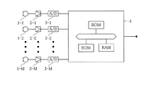
このマイクロフォンアレーシステムは、図1に示すように、マイクロフォンアレーを構成するM個のマイクロフォン1−1〜1−Mと、各マイクロフォンから出力される音声信号をそれぞれ増幅するアンプ2−1〜2−Mと、増幅された音声信号をA/D変換するA/D変換器3−1〜3−Mと、A/D変換された音声信号に対してデジタル信号処理を行い出力する信号処理装置4とから構成されている。
なお、信号処理装置4は、CPU(中央演算装置)、信号処理装置を制御するプログラム等を記憶したROMおよびCPUによる各種演算結果等を記憶するRAM等の記憶装置を有するコンピュータにより実現することも可能である。また、汎用のCPUに代えて、専用の信号処理装置(DSP)を用いてもよい。
[First Embodiment]
FIG. 1 is a diagram showing an outline of a microphone array system according to the first embodiment, and FIG. 2 is a diagram showing a configuration of a signal processing device of the microphone array system.
As shown in FIG. 1, the microphone array system includes M microphones 1-1 to 1-M constituting a microphone array and amplifiers 2-1 to 2-amplifying audio signals output from the microphones. M, A / D converters 3-1 to 3 -M for A / D converting the amplified audio signal, and a
The
信号処理装置4は、図2に示すように、遅延和(DS)処理部41とフィルタ処理部42とから構成されている。
このうちDS処理部41は、A/D変換された各音声信号に対して遅延を付加する遅延器411−1〜411−Mとこれらの遅延器の出力を加算する加算器412とから成り、その基本構成および動作は、従来のDS処理部と同一である。
As shown in FIG. 2, the
Among them, the
フィルタ処理部42は、DS処理部41から出力されるDS処理後の音声信号の調波構造に基づいてフィルタ処理を行うフィルタであり、具体的には、調波構造検出部(ピッチ抽出部)421とフィルタ部422とから構成される。ここでピッチ抽出部421は、公知のピッチ抽出手法によりDS処理部41から出力されるDS処理後の音声信号からその基本ピッチを抽出する。なお、公知のピッチの抽出手法については、例えば、特許文献2、特許文献3等を参照されたい。
一方、フィルタ部422は、低い周波数帯域に対しては、ピッチ抽出部421によって抽出された基本ピッチの整数倍の周波数成分のみを通過させる、一種の櫛型フィルタとして作用するとともに、それ以外の高い周波数帯域に対しては、そのまま通過させるデジタルフィルタである。櫛型フィルタとして作用すべき周波数帯域は、DS処理によっては十分な指向特性を得られない周波数帯とすればよい。この帯域は、マイクロフォンアレーのアレー長に応じて自ずと定めることができる。
The
On the other hand, the
従来のマイクロフォンアレーシステムにおいては、アレー長を十分大きくとれない場合には、周波数帯が低くなると、DS処理によっては十分に鋭い指向特性を得ることができないため、DS処理部41から出力されるDS処理後の音声信号には、収音したい音声信号の他にも音声信号に空調やプロジェクタの雑音等の広帯域雑音が含まれていることが多い。
一方、収音したい音声は、一般的に基本ピッチ(基本周波数)と基本ピッチの整数倍の高調波成分とからなる調波構造を有する。したがって、本実施の形態においては、まず、ピッチ抽出部421において、DS処理部41から出力されるDS処理後の音声信号に含まれる基本ピッチ(基本周波数)を抽出し、フィルタ部422において、この基本ピッチを整数倍することにより、調波構造を検出し、この調波構造に基づくフィルタ処理を行うことにより、広帯域雑音を取り除くことができる。
In the conventional microphone array system, when the array length cannot be made sufficiently large, a sufficiently sharp directivity cannot be obtained depending on the DS processing when the frequency band becomes low. The processed audio signal often includes broadband noise such as air conditioning and projector noise in addition to the audio signal to be collected.
On the other hand, the voice to be collected generally has a harmonic structure composed of a basic pitch (basic frequency) and a harmonic component that is an integral multiple of the basic pitch. Therefore, in the present embodiment, first, the
次に図3を参照して、上述したフィルタ部422の構成について詳述する。
図3に示すように、信号処理装置4のうち、フィルタ処理部42は、ピッチ抽出部421、櫛型フィルタ422a、DS処理部41の出力から高い周波数成分を抽出するハイパスフィルタ(HPF)422b、櫛型フィルタ422aの出力とHPF422bの出力とを加算する加算器422cとから構成することができる。
ここで櫛型フィルタ422aは、ピッチ抽出部421により抽出された基本ピッチの整数倍の周波数成分を通過させるように構成される。したがって、櫛型フィルタ422aからは、DS処理部41から出力される音声信号のうち、調波構造成分のみが出力される。このような櫛型フィルタ422aは、デジタルフィルタにより構成してもよいし、周波数領域において実行するものでもよい。
一方、HPF422bは、DS処理によって十分な指向特性が得られる高い周波数帯の信号成分のみを通過させるように構成されている。したがって、DS処理部41から出力される音声信号のうち、広帯域雑音等を含む低周波成分は、HPF422bによってカットされ、十分な指向特性が得られる高い周波数帯の信号成分のみが出力される。
Next, the configuration of the
As shown in FIG. 3, in the
Here, the
On the other hand, the
このような構成をとることにより、本実施の形態にかかるマイクロフォンアレーシステムは、高い周波数成分についてはDS処理のみを行い、DS処理によっては鋭い指向特性を得ることができない低い周波数帯の信号については、調波構造に基づくフィルタ処理を行っていることになる。
特に、高い周波数成分については、DS処理部41の出力がHPF422bによって供給されるため、例えば無声子音等の比較的高い周波数帯に主要なエネルギーが分布している音声信号の欠落を避けることができる。
By adopting such a configuration, the microphone array system according to the present embodiment performs only DS processing for high frequency components, and for signals in a low frequency band where sharp directivity characteristics cannot be obtained by DS processing. Therefore, the filter processing based on the harmonic structure is performed.
In particular, for high frequency components, since the output of the
なお、本実施の形態の変形例として、図4に示すように、櫛型フィルタ422aの後段にローパスフィルタ(LPF)422dを設け、櫛型フィルタ422aの出力をこのLPF422dを通した上で加算器422cに供給するようにしてもよい。なお、このようなLPF422dは、櫛型フィルタ422aの前段に設けるようにしてもよい。このとき、LPF422dの通過帯域は、DS処理によっては十分な指向特性が得られない低い周波数帯とし、LPF422dとHPF422bとが互いに補完し合うことがより望ましい。これにより音質の劣化を抑えることが可能となる。
As a modification of the present embodiment, as shown in FIG. 4, a low-pass filter (LPF) 422d is provided after the
[第2の実施の形態]
次に本発明の第2の実施の形態について図5を参照して説明する。
第1の実施の形態においては、DS処理部41の出力をピッチ抽出部421の入力とし、DS処理後の音声信号から基本ピッチを抽出するものとして説明したが、本実施の形態は、DS処理前の信号に基づいて基本ピッチを抽出するようにしたものである。
図5は、本実施の形態にかかるマイクロフォンアレーシステムのうち、信号処理装置4の構成を示す図である。ここに示すように、ピッチ抽出部421は、マイクロフォンアレーを構成するM個のマイクロフォンのうち任意の1のマイクロフォンのA/D変換後の音声信号から基本ピッチを抽出するようにしてもよいし、図示はしないが、マイクロフォンアレーとは別に基本ピッチ抽出用のマイクロフォンを設けてもよい。
なお、本実施の形態において、信号処理装置4を除くマイクロフォンアレーの構成は、上述した第1の実施の形態と同様である(図1参照)。また、信号処理装置4の各構成要素も第1の実施の形態と同様である。
[Second Embodiment]
Next, a second embodiment of the present invention will be described with reference to FIG.
In the first embodiment, the output of the
FIG. 5 is a diagram showing the configuration of the
In the present embodiment, the configuration of the microphone array excluding the
[第3の実施の形態]
次に図6乃至9を参照して、本発明の第3の実施の形態について説明する。なお、上述した従来の技術および第1の実施例と同一の構成については、同一の符号を用いることとし、その説明は適宜省略する。
本発明の第3の実施の形態にかかるマイクロフォンアレーシステムは、十分に鋭い指向性特性を得られない結果、マイクロフォンアレーが複数の音源からの音声を検出してしまう場合であっても、それらの到来する方向から音源を判別する手段を備えたものである。
図6に本実施の形態にかかるマイクロフォンアレーシステムの信号処理装置4の構成を示す。本実施の形態において、信号処理装置4は、ピッチ抽出部421と、判別部521と、フィルタ部422とを備えたフィルタ処理部52を有する。
このうち、ピッチ抽出部421は、第1の実施の形態で述べたように、音声信号(本実施の形態においてはDS処理部41の出力信号)からその基本ピッチを抽出する。
[Third Embodiment]
Next, a third embodiment of the present invention will be described with reference to FIGS. In addition, about the same structure as the prior art mentioned above and the 1st Example, the same code | symbol shall be used and the description is abbreviate | omitted suitably.
The microphone array system according to the third exemplary embodiment of the present invention cannot obtain sufficiently sharp directivity characteristics, so that even when the microphone array detects sounds from a plurality of sound sources, Means for discriminating the sound source from the direction of arrival is provided.
FIG. 6 shows a configuration of the
Among these, the
判別部521は、ピッチ抽出部421によって抽出された基本ピッチから得られる調波構造ごとにDS処理前後の信号を比較して、その基本ピッチを有する当該音声が目的方向(θL)から到来したものか否かを判別し、目的方向から到来した音声の基本ピッチをフィルタ部422に出力する。この音源の判別の原理については後述する。
フィルタ部422は、低い周波数帯域に対しては、判別部521によって与えられる基本ピッチの整数倍の周波数成分のみを通過させる、一種の櫛型フィルタとして作用するとともに、それ以外の高い周波数帯域に対しては、そのまま通過させるデジタルフィルタである。その特性は、第1の実施の形態におけるフィルタ部422と同じものである。
The discriminating
The
次に判別部521における音源の判別処理について図7A乃至9を参照して説明する。
(1)音源の方向とDS処理の周波数特性
マイクロフォンアレーの目的方向θLは、DS処理における各遅延量Diを適宜制御することによって定めることができ、その指向特性には周波数依存性があることは、上述したとおりである(例えば、式(1)乃至(4)等参照)。図7Aおよび図7Bは、ともにDS処理後の音声信号の周波数特性を表し、前者は音源が目的方向θLにある場合、後者は音源が目的方向θLから外れた位置にある場合を表す。音源が音源が目的方向θLにある場合には、周波数領域全体にわたってほぼフラットな周波数特性が得られる(図7A)。これに対し、音源が目的方向θLから外れている場合は、低い周波数領域においてはフラットな特性を示すものの、指向特性の周波数依存性により、高い周波数帯域においては、複数の特定の周波数(これらの周波数は、マイクロフォン数M、マイクロフォン間隔d、音源の目的方向とのずれθによって様々である。)にピークが現れるとともに、全体的にゲインが小さくなる傾向がある(図7B)。
したがって、ある音源から到来した音声に関し、周波数領域においてDS処理前の信号とDS処理後の信号とを比較すると、音源が目的方向θLにある場合には、調波構造を構成する各ピーク周波数においてほぼ等しいレベルとなるのに対し、音源が目的方向θLからはずれている場合には、ピーク周波数によって異なるレベルとなる。
Next, the sound source discrimination processing in the
(1) Direction of sound source and frequency characteristics of DS processing The target direction θL of the microphone array can be determined by appropriately controlling each delay amount Di in the DS processing, and the directivity has frequency dependence. As described above (see, for example, formulas (1) to (4)). FIGS. 7A and 7B both show the frequency characteristics of the audio signal after DS processing. The former represents the case where the sound source is in the target direction θL, and the latter represents the case where the sound source is at a position deviating from the target direction θL. When the sound source is in the target direction θL, a substantially flat frequency characteristic can be obtained over the entire frequency domain (FIG. 7A). On the other hand, when the sound source deviates from the target direction θL, it exhibits a flat characteristic in the low frequency range, but due to the frequency dependence of the directivity, a plurality of specific frequencies (these The frequency varies depending on the number of microphones M, the distance between the microphones d, and the deviation θ from the target direction of the sound source.), And the gain tends to decrease as a whole (FIG. 7B).
Therefore, when the signal before the DS processing and the signal after the DS processing are compared in the frequency domain with respect to the sound coming from a certain sound source, when the sound source is in the target direction θL, at each peak frequency constituting the harmonic structure While the levels are almost equal, if the sound source deviates from the target direction θL, the level varies depending on the peak frequency.
(2)調波構造に基づく音源の判別
実環境においては、様々な音源からの複数の信号が入り混じっているため、DS処理前後の信号を単純に比較しても、特定の音源について上述のような周波数特性の違いを見いだすことはまず不可能である。
そこで、本実施の形態においては、各音源が特有の調波構造を有している点に着目し、一の調波構造を構成する倍音列の位置についてのみ、DS処理前の信号とDS処理後の信号とを比較する。これによって、それらの倍音成分が同一の音源から発せられたものであるならば、それらの周波数成分については、DS処理の周波数特性が表れる。したがって、調波構造ごとにDS処理の周波数特性を比較することにより、複数の音源を判別することが可能となる。
(2) Sound source discrimination based on harmonic structure In the actual environment, since a plurality of signals from various sound sources are mixed, even if the signals before and after the DS processing are simply compared, a specific sound source is It is impossible to find such a difference in frequency characteristics.
Therefore, in the present embodiment, paying attention to the point that each sound source has a unique harmonic structure, only the position of the harmonic sequence constituting one harmonic structure and the signal before DS processing and the DS processing. Compare with later signals. As a result, if those harmonic components are emitted from the same sound source, the frequency characteristics of the DS processing appear for those frequency components. Therefore, a plurality of sound sources can be discriminated by comparing the frequency characteristics of the DS processing for each harmonic structure.
このような調波構造に基づく音源の判別方法について、図8乃至図9を参照して説明する。
図8は、特定の音源からの音声のフーリエスペクトルの一例を示す図である。横軸は周波数、縦軸は強度である。ここに示すように、一般的に自然界に存在する音声は調波構造を有しているので、そのフーリエスペクトルは、基本ピッチ(固有振動数)の整数倍の周波数にピークが等間隔に現れる。
図9Aおよび図9Bは、図8に示す調波構造の倍音成分についてDS処理前の音声信号とDS処理後の音声信号との差(以下、倍音成分に関するDS処理の周波数特性を単に「エンベロープ」という。)を示す図である。このうち、図9Aは、音源が目的方向θLにある場合のエンベロープであり、図9Bは、音源が目的方向θLからはずれているときのエンベロープの例である。前者の場合はすべての倍音成分についてほぼ同じ値をとる(すなわちフラットとなる)のに対し、後者の場合は、特に高い周波数領域において異なる値をとることがわかる。
したがって、基本ピッチが異なる調波構造ごとにDS処理による周波数特性を求めることにより、その特徴からその調波構造を有する音源が目的方向θLにあるか否かを判別することができる。
A sound source discrimination method based on such a harmonic structure will be described with reference to FIGS.
FIG. 8 is a diagram illustrating an example of a Fourier spectrum of sound from a specific sound source. The horizontal axis is frequency and the vertical axis is intensity. As shown here, since speech that exists in nature generally has a harmonic structure, the Fourier spectrum has peaks appearing at equal intervals at a frequency that is an integral multiple of the basic pitch (natural frequency).
9A and 9B show the difference between the sound signal before the DS process and the sound signal after the DS process for the harmonic component having the harmonic structure shown in FIG. 8 (hereinafter, the frequency characteristic of the DS process related to the harmonic component is simply “envelope”). It is a figure which shows. 9A is an envelope when the sound source is in the target direction θL, and FIG. 9B is an example of the envelope when the sound source is deviated from the target direction θL. It can be seen that the former case takes almost the same value for all overtone components (ie, becomes flat), whereas the latter case takes a different value particularly in a high frequency region.
Therefore, by determining the frequency characteristics by DS processing for each harmonic structure having a different basic pitch, it is possible to determine whether or not the sound source having the harmonic structure is in the target direction θL from the characteristics.
以上のように、本実施の形態においては、判別部521が調波構造に基づいて音源を判別し、目的方向θLにある音源の調波構造のみをフィルタ部422に与えることができるので、低い周波数帯域においても、マイクロフォンアレーが収音した複数の音源からの音声信号の中から目的方向θLからの音声信号を取り出すことができる。
As described above, in the present embodiment, the
なお、本実施の形態においては、目的方向をθLとする1つのDS処理後の信号に基づいて判別を行うものとして説明したが、目的方向を異にする他のDS処理を同時に行い、そのDS処理後の信号についても同様の判別を行なってもよい。この場合、音源が目的方向θLにある場合には、目的方向を異にするDS処理の特性に基づくエンベロープはフラットにはならないことは明らかである。したがって、目的方向を異にする2以上のエンベロープを取得し、エンベロープがフラットにはならない、という情報をも積極的に活用することによって、判別の精度をより向上させることが可能となる。 In the present embodiment, it has been described that the determination is performed based on a signal after one DS process in which the target direction is θL. However, other DS processes with different target directions are performed simultaneously, and the DS is processed. The same determination may be made for the processed signal. In this case, when the sound source is in the target direction θL, it is clear that the envelope based on the characteristics of the DS processing with different target directions does not become flat. Therefore, by acquiring two or more envelopes having different target directions and actively utilizing information that the envelope does not become flat, it is possible to further improve the accuracy of determination.
また、本実施の形態においては、複数の音源からの音声が入り交じった信号から音源ごとの調波構造を特定する方法として、ピッチ抽出部421において、公知のピッチ抽出手法により各音声信号に含まれる基本ピッチを抽出してもよいが、音声信号のスペクトルの時間的変化に基づいて一の音源から到来する音声の調波構造を特定するようにしてもよい。
図10は、音声信号のスペクトルの時間的変化の一例を示す図である。縦軸に周波数、横軸は時間を表す。図10においては、異なる音源(例えば話者A,話者B)からの音声の周波数スペクトルが、それらの調波構造とともに異なる時間に出現する様子が示されている。ここでは、話者Aは時間t1 に話し始め、話者Bは時間t2 に話し始めている。このように、調波構造検出部421において、音声信号のスペクトルの時間的変化、例えば、調波構造を示すスペクトルの出現やそのピークのタイミング等に基づいて各音源の調波構造を特定するようにしてもよい。
Further, in the present embodiment, as a method for identifying the harmonic structure for each sound source from a signal in which sounds from a plurality of sound sources are mixed, the
FIG. 10 is a diagram illustrating an example of a temporal change in the spectrum of an audio signal. The vertical axis represents frequency and the horizontal axis represents time. FIG. 10 shows how the frequency spectra of voices from different sound sources (for example, speaker A and speaker B) appear at different times together with their harmonic structures. Here, speaker A begins speaking at time t1, and speaker B begins speaking at time t2. As described above, the harmonic
また、本実施の形態の変形例として、図11に示すように、ピッチ抽出部421がDS処理前の信号に基づいて基本ピッチを抽出するように構成してもよい。また、フィルタ部422に代えて櫛型フィルタ422aを設け、その出力をHPF422bの出力と加算するようにしてもよい。
As a modification of the present embodiment, as shown in FIG. 11, the
[第4の実施の形態]
本発明の第4の実施の形態にかかる信号処理装置の構成を図12に示す。この信号処理装置は、図11に示した信号処理装置4のフィルタ処理部52のうち、フィルタ部422aとHPF422bを省略し、調波構造検出部(ピッチ抽出部)421および判別部521からフィルタ処理部52’を構成し、このフィルタ処理部52’とDS処理部41と組み合わせ、音源方向判別装置としたものである。
このような音源方向判別装置においては、調波構造検出部421によって抽出された基本ピッチから得られる調波構造ごとにDS処理前後の信号を比較して、その基本ピッチを有する当該音声が目的方向(θL)から到来したものか否かを判別する。したがって、複数の話者が存在する場合でも、これらの話者から発せられる音声の調波構造がそれぞれ異なれば、話者ごとに方向を特定することが可能となる。図示はしないが、このとき、DS処理部41の遅延量D1〜DMからそのときの目的方向(θL)を算出し、これ出力するようにしてもよい。
[Fourth Embodiment]
FIG. 12 shows the configuration of a signal processing apparatus according to the fourth embodiment of the present invention. This signal processing device omits the
In such a sound source direction discriminating apparatus, signals before and after the DS processing are compared for each harmonic structure obtained from the fundamental pitch extracted by the harmonic
また、本実施の形態においては、調波構造検出部421を用いてマイクロフォンによって収集した音声信号の調波構造を特定しているが、変形例として、この調波構造検出部421に代えて、メモリ等の記憶手段を設け、これに目的とする音源の持つ調波構造を記憶させておき、マイクロフォンアレーの指向特性を変化させることにより、目的とする音源の方向を特定することができる。
また、音源がマイクロフォンアレーの正面にあるか否かを判断するのであれば、DS処理部41の遅延部411−1〜411−Mは不要となる。
In the present embodiment, the harmonic structure of the audio signal collected by the microphone is specified using the harmonic
Further, if it is determined whether the sound source is in front of the microphone array, the delay units 411-1 to 411 -M of the
1−1〜1−M…マイクロフォン、2−1〜2−M…アンプ、3−1〜3−M…A/Dコンバータ、4…信号処理装置、41…遅延和処理部、411−1〜411−M…遅延器、412…加算器、42,52,52’…フィルタ処理部、421…調波構造抽出部(ピッチ抽出部)、422…フィルタ部、422a…櫛型フィルタ,422b…HPF、422c…加算器、422d…LPF、521…判別部、。
DESCRIPTION OF SYMBOLS 1-1 to 1-M ... Microphone, 2-1 to 2-M ... Amplifier, 3-1 to 3-M ... A / D converter, 4 ... Signal processing apparatus, 41 ... Delay sum processing part, 411-1 411-M ... delay unit, 412 ... adder, 42, 52, 52 '... filter processing unit, 421 ... harmonic structure extraction unit (pitch extraction unit), 422 ... filter unit, 422a ... comb filter, 422b ...
Claims (8)
それぞれ遅延を付加された前記複数の音声信号の総和をとる加算手段と、
前記音声信号に含まれる音声の調波構造を検出する検出手段と、
検出された調波構造に基づいて所定の周波数成分を選択的に通過させるフィルタ手段と
を備えたことを特徴とするマイクロフォンアレー用信号処理装置。 Delay means for adding delay to a plurality of audio signals respectively output from a plurality of microphones constituting a microphone array;
Adding means for taking the sum of the plurality of audio signals each with a delay added thereto;
Detecting means for detecting a harmonic structure of a voice included in the voice signal;
A microphone array signal processing apparatus, comprising: filter means for selectively passing a predetermined frequency component based on the detected harmonic structure.
前記検出手段は、前記音声信号に含まれる基本ピッチを抽出する手段を含み、
前記フィルタ手段は、前記加算手段から出力される音声信号のうち、抽出された前記基本ピッチの整数倍の周波数成分を選択的に通過させる
ことを特徴とするマイクロフォンアレー用信号処理装置。 In the microphone array signal processing device according to claim 1,
The detecting means includes means for extracting a basic pitch included in the audio signal;
The filter means selectively passes a frequency component that is an integral multiple of the extracted basic pitch in the audio signal output from the adding means.
前記検出手段は、前記音声信号のスペクトルの時間的変化に基づいて一の音源から到来する音声信号の調波構造を特定する
ことを特徴とするマイクロフォンアレー用信号処理装置。 In the microphone array signal processing device according to claim 1,
The signal processing apparatus for a microphone array, wherein the detection unit specifies a harmonic structure of an audio signal arriving from one sound source based on a temporal change in a spectrum of the audio signal.
前記フィルタ手段は、
前記加算手段の出力のうち高周波成分を通過させるハイパスフィルタと、
前記調波構造に基づいて所定の周波数成分を通過させる櫛型フィルタと、
前記ハイパスフィルタの出力と前記櫛型フィルタの出力とを加算して出力する出力手段と
を備えたことを特徴とするマイクロフォンアレー用信号処理装置。 The microphone array signal processing device according to any one of claims 1 to 3,
The filter means includes
A high-pass filter that passes high-frequency components of the output of the adding means;
A comb filter that allows a predetermined frequency component to pass based on the harmonic structure;
A signal processing apparatus for a microphone array, comprising output means for adding and outputting the output of the high-pass filter and the output of the comb filter.
さらに音源を判別する判別手段を備え、
前記フィルタ手段は、前記判別手段によって判別された任意の音源から到来する音声信号の調波構造に基づいて所定の周波数成分を選択的に通過させることを特徴とするマイクロフォンアレー。 In the microphone array signal processing device according to any one of claims 1 to 4,
Furthermore, it has a discrimination means for discriminating the sound source,
The microphone array selectively passes a predetermined frequency component based on a harmonic structure of an audio signal coming from an arbitrary sound source determined by the determination unit.
前記判別手段は、
音声信号の調波構造と前記遅延手段および前記加算手段による遅延和処理の周波数特性とに基づいて前記音源を判別することを特徴とするマイクロフォンアレー用信号処理装置。 The signal processing apparatus for a microphone array according to claim 5,
The discrimination means includes
6. A microphone array signal processing apparatus, wherein the sound source is discriminated based on a harmonic structure of an audio signal and frequency characteristics of delay-and-sum processing by the delay means and the addition means.
それぞれ遅延を付加された前記複数の音声信号の総和をとる加算手段と、
前記音声信号に含まれる音声の調波構造を検出する検出手段と、
音声信号の調波構造と前記遅延手段および前記加算手段による遅延和処理の周波数特性とに基づいて前記音源を判別する判別手段と
を備えたことを特徴とするマイクロフォンアレー用信号処理装置。 Delay means for adding delay to a plurality of audio signals respectively output from a plurality of microphones constituting a microphone array;
Adding means for taking the sum of the plurality of audio signals each with a delay added thereto;
Detecting means for detecting a harmonic structure of a voice included in the voice signal;
A microphone array signal processing apparatus comprising: a discrimination unit that discriminates the sound source based on a harmonic structure of an audio signal and a frequency characteristic of delay sum processing by the delay unit and the addition unit.
このマイクロフォンアレーを構成する前記マイクロフォンからそれぞれ出力される音声信号を処理するマイクロフォンアレー用信号処理装置を備えたマイクロフォンアレーシステムにおいて、
前記マイクロフォンアレー用信号処理装置は、
請求項1乃至7のいずれか1つに記載されたマイクロフォンアレー用信号処理装置であることを特徴とするマイクロフォンアレーシステム。
A microphone array comprising a plurality of spatially arranged microphones;
In a microphone array system including a microphone array signal processing device that processes audio signals output from the microphones constituting the microphone array,
The microphone array signal processing apparatus comprises:
A microphone array system according to any one of claims 1 to 7, wherein the microphone array system is a signal processing apparatus for a microphone array.
Priority Applications (4)
| Application Number | Priority Date | Filing Date | Title |
|---|---|---|---|
| JP2005058785A JP4407538B2 (en) | 2005-03-03 | 2005-03-03 | Microphone array signal processing apparatus and microphone array system |
| EP06004398.1A EP1699260A3 (en) | 2005-03-03 | 2006-03-03 | Microphone array signal processing apparatus, microphone array signal processing method, and microphone array system |
| US11/368,073 US20060198536A1 (en) | 2005-03-03 | 2006-03-03 | Microphone array signal processing apparatus, microphone array signal processing method, and microphone array system |
| US12/753,215 US8218787B2 (en) | 2005-03-03 | 2010-04-02 | Microphone array signal processing apparatus, microphone array signal processing method, and microphone array system |
Applications Claiming Priority (1)
| Application Number | Priority Date | Filing Date | Title |
|---|---|---|---|
| JP2005058785A JP4407538B2 (en) | 2005-03-03 | 2005-03-03 | Microphone array signal processing apparatus and microphone array system |
Publications (2)
| Publication Number | Publication Date |
|---|---|
| JP2006246007A true JP2006246007A (en) | 2006-09-14 |
| JP4407538B2 JP4407538B2 (en) | 2010-02-03 |
Family
ID=36569743
Family Applications (1)
| Application Number | Title | Priority Date | Filing Date |
|---|---|---|---|
| JP2005058785A Expired - Fee Related JP4407538B2 (en) | 2005-03-03 | 2005-03-03 | Microphone array signal processing apparatus and microphone array system |
Country Status (3)
| Country | Link |
|---|---|
| US (2) | US20060198536A1 (en) |
| EP (1) | EP1699260A3 (en) |
| JP (1) | JP4407538B2 (en) |
Families Citing this family (6)
| Publication number | Priority date | Publication date | Assignee | Title |
|---|---|---|---|---|
| US7626889B2 (en) * | 2007-04-06 | 2009-12-01 | Microsoft Corporation | Sensor array post-filter for tracking spatial distributions of signals and noise |
| JPWO2009004718A1 (en) * | 2007-07-03 | 2010-08-26 | パイオニア株式会社 | Musical sound enhancement device, musical sound enhancement method, musical sound enhancement program, and recording medium |
| US9685730B2 (en) | 2014-09-12 | 2017-06-20 | Steelcase Inc. | Floor power distribution system |
| US9584910B2 (en) | 2014-12-17 | 2017-02-28 | Steelcase Inc. | Sound gathering system |
| CN109859749A (en) * | 2017-11-30 | 2019-06-07 | 阿里巴巴集团控股有限公司 | A kind of voice signal recognition methods and device |
| CN109831731B (en) * | 2019-02-15 | 2020-08-04 | 杭州嘉楠耘智信息科技有限公司 | Sound source orientation method and device and computer readable storage medium |
Family Cites Families (18)
| Publication number | Priority date | Publication date | Assignee | Title |
|---|---|---|---|---|
| JP2713102B2 (en) | 1993-05-28 | 1998-02-16 | カシオ計算機株式会社 | Sound signal pitch extraction device |
| JPH09140000A (en) | 1995-11-15 | 1997-05-27 | Nippon Telegr & Teleph Corp <Ntt> | Loud hearing aid for conference |
| JP3552837B2 (en) | 1996-03-14 | 2004-08-11 | パイオニア株式会社 | Frequency analysis method and apparatus, and multiple pitch frequency detection method and apparatus using the same |
| JP3344647B2 (en) * | 1998-02-18 | 2002-11-11 | 富士通株式会社 | Microphone array device |
| EP1230739B1 (en) * | 1999-11-19 | 2016-05-25 | Gentex Corporation | Vehicle accessory microphone |
| JP2001337694A (en) * | 2000-03-24 | 2001-12-07 | Akira Kurematsu | Method for presuming speech source position, method for recognizing speech, and method for emphasizing speech |
| WO2002029782A1 (en) * | 2000-10-02 | 2002-04-11 | The Regents Of The University Of California | Perceptual harmonic cepstral coefficients as the front-end for speech recognition |
| JP2002175099A (en) | 2000-12-06 | 2002-06-21 | Hioki Ee Corp | Method and device for noise suppression |
| US6930235B2 (en) * | 2001-03-15 | 2005-08-16 | Ms Squared | System and method for relating electromagnetic waves to sound waves |
| CA2388352A1 (en) * | 2002-05-31 | 2003-11-30 | Voiceage Corporation | A method and device for frequency-selective pitch enhancement of synthesized speed |
| JP3513662B1 (en) * | 2003-02-05 | 2004-03-31 | 鐵夫 杉岡 | Cogeneration system |
| US7512245B2 (en) * | 2003-02-25 | 2009-03-31 | Oticon A/S | Method for detection of own voice activity in a communication device |
| US7643641B2 (en) * | 2003-05-09 | 2010-01-05 | Nuance Communications, Inc. | System for communication enhancement in a noisy environment |
| US7949057B2 (en) * | 2003-10-23 | 2011-05-24 | Panasonic Corporation | Spectrum coding apparatus, spectrum decoding apparatus, acoustic signal transmission apparatus, acoustic signal reception apparatus and methods thereof |
| TWI230023B (en) * | 2003-11-20 | 2005-03-21 | Acer Inc | Sound-receiving method of microphone array associating positioning technology and system thereof |
| US20070076898A1 (en) * | 2003-11-24 | 2007-04-05 | Koninkiljke Phillips Electronics N.V. | Adaptive beamformer with robustness against uncorrelated noise |
| DE602005007219D1 (en) * | 2004-02-20 | 2008-07-10 | Sony Corp | Method and device for separating sound source signals |
| JP4729927B2 (en) * | 2005-01-11 | 2011-07-20 | ソニー株式会社 | Voice detection device, automatic imaging device, and voice detection method |
-
2005
- 2005-03-03 JP JP2005058785A patent/JP4407538B2/en not_active Expired - Fee Related
-
2006
- 2006-03-03 US US11/368,073 patent/US20060198536A1/en not_active Abandoned
- 2006-03-03 EP EP06004398.1A patent/EP1699260A3/en not_active Withdrawn
-
2010
- 2010-04-02 US US12/753,215 patent/US8218787B2/en not_active Expired - Fee Related
Also Published As
| Publication number | Publication date |
|---|---|
| US20060198536A1 (en) | 2006-09-07 |
| EP1699260A3 (en) | 2013-04-10 |
| EP1699260A2 (en) | 2006-09-06 |
| US8218787B2 (en) | 2012-07-10 |
| US20100189279A1 (en) | 2010-07-29 |
| JP4407538B2 (en) | 2010-02-03 |
Similar Documents
| Publication | Publication Date | Title |
|---|---|---|
| US8612217B2 (en) | Method and system for noise reduction | |
| US9986332B2 (en) | Sound pick-up apparatus and method | |
| JP5305743B2 (en) | Sound processing apparatus and method | |
| US8885839B2 (en) | Signal processing method and apparatus | |
| JP4407538B2 (en) | Microphone array signal processing apparatus and microphone array system | |
| JP6065028B2 (en) | Sound collecting apparatus, program and method | |
| JP2008219458A (en) | Sound source separator, sound source separation program and sound source separation method | |
| JP6540730B2 (en) | Sound collection device, program and method, determination device, program and method | |
| JP2011099967A (en) | Sound signal processing method and sound signal processing device | |
| JP5642339B2 (en) | Signal separation device and signal separation method | |
| US10085087B2 (en) | Sound pick-up device, program, and method | |
| WO2015125191A1 (en) | Voice signal processing device and voice signal processing method | |
| JP2010124370A (en) | Signal processing device, signal processing method, and signal processing program | |
| US10015592B2 (en) | Acoustic signal processing apparatus, method of processing acoustic signal, and storage medium | |
| JP6048596B2 (en) | Sound collector, input signal correction method for sound collector, and mobile device information system | |
| US10366703B2 (en) | Method and apparatus for processing audio signal including shock noise | |
| JP6436180B2 (en) | Sound collecting apparatus, program and method | |
| CN113660578B (en) | Directional pickup method and device with adjustable pickup angle range for double microphones | |
| JP5105336B2 (en) | Sound source separation apparatus, program and method | |
| US11825264B2 (en) | Sound pick-up apparatus, storage medium, and sound pick-up method | |
| JP6065029B2 (en) | Sound collecting apparatus, program and method | |
| JP5633145B2 (en) | Sound signal processing device | |
| EP3513573B1 (en) | A method, apparatus and computer program for processing audio signals | |
| JP2006072163A (en) | Disturbing sound suppressing device | |
| JP6252274B2 (en) | Background noise section estimation apparatus and program |
Legal Events
| Date | Code | Title | Description |
|---|---|---|---|
| A621 | Written request for application examination |
Free format text: JAPANESE INTERMEDIATE CODE: A621 Effective date: 20080122 |
|
| A977 | Report on retrieval |
Free format text: JAPANESE INTERMEDIATE CODE: A971007 Effective date: 20090701 |
|
| A131 | Notification of reasons for refusal |
Free format text: JAPANESE INTERMEDIATE CODE: A131 Effective date: 20090714 |
|
| A521 | Written amendment |
Free format text: JAPANESE INTERMEDIATE CODE: A523 Effective date: 20090909 |
|
| TRDD | Decision of grant or rejection written | ||
| A01 | Written decision to grant a patent or to grant a registration (utility model) |
Free format text: JAPANESE INTERMEDIATE CODE: A01 Effective date: 20091020 |
|
| A01 | Written decision to grant a patent or to grant a registration (utility model) |
Free format text: JAPANESE INTERMEDIATE CODE: A01 |
|
| A61 | First payment of annual fees (during grant procedure) |
Free format text: JAPANESE INTERMEDIATE CODE: A61 Effective date: 20091102 |
|
| R150 | Certificate of patent or registration of utility model |
Free format text: JAPANESE INTERMEDIATE CODE: R150 |
|
| FPAY | Renewal fee payment (event date is renewal date of database) |
Free format text: PAYMENT UNTIL: 20121120 Year of fee payment: 3 |
|
| FPAY | Renewal fee payment (event date is renewal date of database) |
Free format text: PAYMENT UNTIL: 20121120 Year of fee payment: 3 |
|
| FPAY | Renewal fee payment (event date is renewal date of database) |
Free format text: PAYMENT UNTIL: 20131120 Year of fee payment: 4 |
|
| LAPS | Cancellation because of no payment of annual fees |