JP2006244407A - Display device - Google Patents
Display device Download PDFInfo
- Publication number
- JP2006244407A JP2006244407A JP2005062891A JP2005062891A JP2006244407A JP 2006244407 A JP2006244407 A JP 2006244407A JP 2005062891 A JP2005062891 A JP 2005062891A JP 2005062891 A JP2005062891 A JP 2005062891A JP 2006244407 A JP2006244407 A JP 2006244407A
- Authority
- JP
- Japan
- Prior art keywords
- circuit
- display device
- scanning lines
- display
- filter
- Prior art date
- Legal status (The legal status is an assumption and is not a legal conclusion. Google has not performed a legal analysis and makes no representation as to the accuracy of the status listed.)
- Pending
Links
Images


Abstract
Description
本発明は、画像取込み機能を備えた表示装置に関する。 The present invention relates to a display device having an image capturing function.
近年、携帯電話、ノート型コンピュータ等の各種機器の表示装置として、液晶表示装置や有機ELディスプレイなどの開発が進められている。 In recent years, liquid crystal display devices and organic EL displays have been developed as display devices for various devices such as mobile phones and notebook computers.
一般に、液晶表示装置は、複数の走査線と複数の信号線との各交差部に薄膜トランジスタ(TFT)、液晶容量、及び、補助容量を有する表示画素が配列したアレイ基板と、走査線及び信号線を駆動する駆動回路とを備えている。近年では、集積回路技術の発展およびプロセス技術の実用化により駆動回路の一部もアレイ基板上に形成され得るようになり、液晶表示装置全体の軽薄短小化が図られている。 In general, a liquid crystal display device includes an array substrate in which display pixels having thin film transistors (TFTs), liquid crystal capacitors, and auxiliary capacitors are arranged at intersections of a plurality of scanning lines and a plurality of signal lines, and scanning lines and signal lines. And a drive circuit for driving. In recent years, with the development of integrated circuit technology and the practical application of process technology, a part of the drive circuit can be formed on the array substrate, and the entire liquid crystal display device has been reduced in size and thickness.
一方、アレイ基板上に画像取り込み機能を有する密着型エリアセンサを配置した画像取り込み機能付き表示装置が光入力機能付き表示装置として提案されている。 On the other hand, a display device with an image capturing function in which a contact area sensor having an image capturing function is arranged on an array substrate has been proposed as a display device with an optical input function.
この種の画像取り込み機能を有する従来の液晶表示装置は、複数の走査線と複数の信号線との各交差部に配列された例えば液晶画素部などからなる表示手段と、例えばフォトダイオードなどからなる光検知手段を有し、この光検知手段を構成するフォトダイオードに接続されたキャパシタの電荷量をフォトダイオードでの受光量に応じて変化させ、キャパシタの両端の電圧を検出することにより画像データを生成し、画像取り込みを行っている。 A conventional liquid crystal display device having this type of image capturing function includes a display unit including, for example, a liquid crystal pixel unit arranged at each intersection of a plurality of scanning lines and a plurality of signal lines, and a photodiode, for example. The image data is obtained by detecting the voltage at both ends of the capacitor by changing the amount of charge of the capacitor connected to the photodiode constituting the light detecting means according to the amount of light received by the photodiode. Generate and capture images.
このような画像取り込み機能を有する表示装置において、複数の撮像条件で得られた画像データから画像処理によって入射光の照射強度に対応した多階調画像データを得る手法が提案されている。 In a display device having such an image capturing function, a method for obtaining multi-gradation image data corresponding to the irradiation intensity of incident light from image data obtained under a plurality of imaging conditions by image processing has been proposed.
また、画像を表示する表示フレームの間に撮像フレームを挿入することにより画像の表示を行いながら画像を取り込む手法も提案されている。この手法を用いると、表示装置の表示画面に指を触れたり、または例えばペン型の光源を用いて表示画面に光を照射したりすることにより、表示装置の座標入力デバイスとして使用することが可能であり、座標算出アルゴリズムやクリック検出アルゴリズムなどが提案されている。 There has also been proposed a method for capturing an image while displaying an image by inserting an imaging frame between display frames for displaying the image. When this method is used, it can be used as a coordinate input device for a display device by touching the display screen of the display device with a finger or irradiating light on the display screen using, for example, a pen-type light source. Coordinate calculation algorithms and click detection algorithms have been proposed.
上述した従来の画像取り込み機能付き表示装置では、製造プロセスに起因して発生した点状欠損や線状欠損のある画像データをそのまま外部に出力しているため、外部のICを用いて欠損を補完する画像処理が必要となる。この画像処理を行うためには通常IC内部に画像データ数ライン分のメモリを必要とするため、ICの回路規模が大きくなりコストも高くなるという問題があった。 In the above-described conventional display device with an image capturing function, image data having a dot defect or a line defect generated due to a manufacturing process is output to the outside as it is, so that the defect is compensated by using an external IC. Image processing is required. In order to perform this image processing, a memory corresponding to several lines of image data is usually required in the IC, so that there is a problem that the circuit scale of the IC increases and the cost also increases.
逆に外部のICで補完処理を行わない場合、欠損のない画像取り込み機能付き表示装置のみを選別する必要があるため製造歩留りが低下してしまうという問題があった。
本発明は、上記の問題点に鑑みてなされたものであって、点状欠損や線状欠損で一部欠落した部分を補完するとともに、外部ICの回路規模増大及びコスト上昇を抑え、かつ、製造歩留まりの高い画像取り込み機能付き表示装置を提供することを目的とする。 The present invention has been made in view of the above-described problems, and complements a part that is partially lost due to a point defect or a line defect, and suppresses an increase in circuit scale and cost of an external IC, and It is an object of the present invention to provide a display device with an image capturing function having a high manufacturing yield.
本発明の一様態による表示装置は、並行に配列された複数の走査線と、前記複数の走査線に交差するように配列された複数の信号線と、前記複数の走査線と前記複数の信号線との交差部に配列された複数の表示画素と、前記複数の表示画素の1つまたは複数毎に少なくとも1つ設けられた光検知部と、前記複数の走査線と前記複数の信号線とを介して前記複数の表示画素を駆動する駆動手段と、前記光検知部を制御する出力制御部と、を備え、前記出力制御部は、少なくとも前記表示画素に表示される画像の階調値を補完するフィルタを有するものである。 A display device according to one embodiment of the present invention includes a plurality of scanning lines arranged in parallel, a plurality of signal lines arranged to intersect the plurality of scanning lines, the plurality of scanning lines, and the plurality of signals. A plurality of display pixels arranged at intersections with the lines, at least one photodetecting unit provided for each one or a plurality of the display pixels, the plurality of scanning lines, and the plurality of signal lines, Driving means for driving the plurality of display pixels via an output controller, and an output control unit for controlling the light detection unit, wherein the output control unit determines at least a gradation value of an image displayed on the display pixel. It has a complementary filter.
本発明によれば、点状欠損や線状欠損のある画像データを補完するとともに、外部ICの回路規模増大及びコスト上昇を抑え、かつ、製造歩留まりの高い画像取り込み機能付き表示装置を提供することが可能である。 According to the present invention, it is possible to provide a display device with an image capturing function that complements image data having a point defect or a line defect, suppresses an increase in circuit scale and cost of an external IC, and has a high manufacturing yield. Is possible.
以下、図面を用いて、本発明を実施するための最良の形態(以下、実施形態と称する)を説明する。 Hereinafter, the best mode for carrying out the present invention (hereinafter referred to as an embodiment) will be described with reference to the drawings.
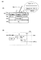
図1は画像取り込み機能付き表示装置のアレイ基板100と、アレイ基板100の撮像動作を制御し、撮像データを受け取って処理を行う外部IC200との動作を説明するブロック図である。図1に示すように、画像取り込み機能付き表示装置10は、例えば、ガラス基板上のポリシリコン薄膜トランジスタ回路で駆動される液晶ディスプレイである。
FIG. 1 is a block diagram for explaining the operations of the
外部IC200は専用に作られたASIC、デジタルシグナルプロセッサDSP、中央演算装置CPU等であり、撮像画像をディスプレイに再表示したり、ストレージデバイスに保存したり、あるいは撮像画像を処理することによって座標入力を行うなどの様々な処理を行うものである。ただし、ここでは外部IC200によって表示動作を制御する部分の説明は省略する。
The
アレイ基板100上の表示領域110には、並行に配列された複数の走査線Xと、複数の走査線Xに交差するように配列された複数の信号線Yが形成されている。図1には、走査線X(n)と信号線Y(m)をそれぞれ1本ずつ示している。複数の走査線Xと複数の信号線Yとの交差部120には、表示手段としての画素回路122及び、光検知手段としてのセンサ回路124が配列されている。図1には、1つの画素回路122及び1つのセンサ回路124を代表して示している。
In the
アレイ基板100上の表示領域110の周囲には、複数の走査線Xと複数の信号線Yとを介して画像回路122を駆動する駆動回路が形成されている。この駆動回路は、複数の画素回路122を行単位で駆動する走査線駆動回路132と、駆動される画素回路122にそれぞれの画像信号を供給する信号線駆動回路134とを有する。
Around the
また、アレイ基板100上の表示領域110の周囲には、複数のセンサ回路124を制御するための制御手段が設けられている。この制御手段は、センサ回路124をプリチャージするプリチャージ回路138と、センサ回路124を行単位で指定するためのセンサ制御回路136と、センサ回路124からの出力をアナログ/デジタル変換するA/D変換部140と、A/D変換部140が出力するデジタルデータを受信し、外部IC200に出力する出力制御部150と、を有している。出力制御部150は、フィルタ152とデータ転送部154とを含む。
A control means for controlling the plurality of
アレイ基板100では、まず交差部120に設けられたセンサ回路124を用いて入射光強度の情報をアナログ信号に変換し、そのアナログ信号をアレイ基板100周辺に設けられたA/D変換部140によってデジタル画像データに変換する。そのデジタル画像データは、アレイ基板100周辺に設けられた撮像データの出力制御部150によって外部IC200に出力される。出力制御部150は、フィルタ152とデータ転送部154とを有している。A/D変換部140から出力されたデータは、出力制御部150のフィルタ152でフィルタ処理され、データ転送部154によってシリアルに外部IC200に出力される。
In the
図2(A)、図2(B)に、図1に示した画素回路122、及び、センサ回路124の基本的な回路構成例を示す。図2(A)に示すように、アレイ基板100には、ライトペン700によって光入力が成されている。アレイ基板(ガラス基板)100の外側には、ガラス保護のために透明膜102がコーティングまたは貼り付けられている。アレイ基板100の内面側には、ここでは図示されていない複数の走査線X、複数の信号線Y、画素回路122及びセンサ回路124が印刷技術及び蒸着技術を用いて形成されている。
2A and 2B illustrate basic circuit configuration examples of the
アレイ基板100の内面側に形成されたPINダイオードD1、D2、D3は、それぞれセンサ回路124内で光感応素子として機能する。PINダイオードD1、D2、D3の周囲は、絶縁層103によって囲まれている。また、絶縁層103には、PINダイオードD1、D2、D3に対向して遮光膜SH1、SH2、SH3が形成されている。
The PIN diodes D1, D2, and D3 formed on the inner surface side of the
アレイ基板100と間隔をおいて、対向基板105が配置されている。対向基板105は、共通電極(透明電極)を有するとともに、アレイ基板100と対向している。アレイ基板100と対向基板105との間には液晶層104が狭持されている。対向基板105の外側には、バックライト106が配置されている。バックライト106から照射された光は、対向基板105、液晶層104、及び、アレイ基板100を透過する際に、その透過状態が制御され、表示画面に画像が得られる。
A
図2(B)には、1つのセンサ回路124の基本的な回路構成例を示している。信号線Y(m)には、スイッチ(薄膜トランジスタ)TR2のソースが接続されている。スイッチTR2のドレインはフォトダイオードPDのカソードに接続されるとともに、センサ容量CPの一方の電極に接続されている。フォトダイオードPDのアノード、及び、センサ容量CPの他方の電極は、所定の電位のアースラインに接続されている。スイッチTR2のゲートは、リセット制御ラインCRT(n)に接続されている。
FIG. 2B illustrates a basic circuit configuration example of one
上記のセンサ回路124は、特定の水平ブランキング期間の後半で、センサ容量CPにプリチャージが行われ、次の周期(1垂直期間後)の特定水平ブランキング期間の前半で読み出しが行われる。プリチャージ後、フォトダイオードPDに照射される光量が多い場合は、センサ容量CPの放電量が多い。逆にフォトダイオードPDに照射される光量が少ない場合は、センサ容量CPの放電量が少ない。なお、フォトダイオードPDとバックライトとの間には遮光処理が成されている。したがって、読み出し期間にセンサ容量CPの電圧を、増幅器を介して出力することで、センサ出力を得ることができる。
In the
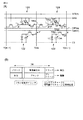
図3(A)には、上記の画素回路122、及び、センサ回路124の一構成例を示している。図3(A)に示すように、電圧ラインCsは、補助容量Csk及び液晶LCの一方の電極に所定の周期で所定の電位を与える電圧ラインである。ゲートラインGate(n)は、画素回路122の駆動トランジスタTR1をオンオフ制御するためのゲートラインである。
FIG. 3A illustrates a configuration example of the
また、リセット制御ラインCRT(n)は、センサ回路124を構成するスイッチTR2をオンオフ制御するための制御信号ラインである。スイッチTR2がオンしたときに、センサ容量CPにプリチャージが行われる。GNDは、接地ラインである。また、SFB(n)は、センサ容量CPの電位を読み出すときに薄膜トランジスタTR4をオンするセンサ出力制御ラインである。薄膜トランジスタTR3は増幅素子として機能する。フォトダイオードPDは、光に感応し、光量に応じた電流を流す。これにより、センサ容量CPにプリチャージされている電荷を放出することができる。
The reset control line CRT (n) is a control signal line for ON / OFF control of the switch TR2 constituting the
信号線Y(m−1)、Y(m)、Y(m+1)は図1に示した信号線駆動回路134、及びA/D変換部140に接続されている。また、電源ラインCs、ゲートラインGate(n)は、図1に示した走査線駆動回路132に接続され、リセット制御ラインCRT(n)、接地ラインGND、及び、センサ制御ラインSFB(n)はセンサ制御回路136に接続されている。
The signal lines Y (m−1), Y (m), and Y (m + 1) are connected to the signal
図3(B)に、上記の回路の動作を説明するためのタイミングチャートを示す。上記の回路は、1垂直期間(1フレーム期間)内の特定の1水平期間を次のように設定している。画素回路122では、1水平期間(1H)内を、第1ブランク期間、コモン反転ブランク期間、書き込み期間、及び、第2ブランク期間に分けている。この4つの期間に対応させてセンサ回路124では、出力期間、コモン反転タイミング期間、プリチャージ期間に分けている。1垂直期間(1フレーム期間)内の上記4つの期間以外は、画素回路122は表示期間で、センサ回路124は撮像期間である。
FIG. 3B is a timing chart for explaining the operation of the above circuit. In the above circuit, one specific horizontal period within one vertical period (one frame period) is set as follows. In the
画素回路122では、補助容量Cskに対して信号線Y(m+1)を介して、書き込み期間に矢印a1に示すような経路で画像信号が書き込まれる。この容量Cskの両端間に生じた電圧値に応じて液晶LCが駆動され階調表示される。
In the
センサ回路124では、上記書き込み期間に続いて、トランジスタTR2がオンされ、容量CPに対してプリチャージが行われる。このとき信号線Y(m+1)を介して矢印b1、及び矢印c1に示すような経路で容量CPがプリチャージされる。つまり、書き込み期間とプリチャージ期間とがずれており、信号線Yを有効に利用している。撮像期間においてフォトダイオードPDに電流が流れると、プリチャージ電圧が変化する。
In the
次の1フレームサイクルで、出力期間にトランジスタTR4がオンされると、センサ容量CPの電圧がトランジスタTR3で増幅され、信号線Y(m)を介して取り出される(矢印d1、e1の経路)。隣の水平ラインの画素及びセンサ部においても次の1水平期間に同様の動作が実行される。センサ容量CPから取り出された電圧は、プリチャージ以後、読み出しスタートまでの間、フォトダイオードPDが遮光されていた時間に応じて変化する。全く遮光されていない場合は、読み出された電圧は十分に低い状態で、遮光されていた時間が長い場合は、高い電圧が得られる。これによりライトペン700によってインプットが成されたのかどうかを判断する。 In the next one frame cycle, when the transistor TR4 is turned on during the output period, the voltage of the sensor capacitor CP is amplified by the transistor TR3 and taken out via the signal line Y (m) (paths of arrows d1 and e1). The same operation is also performed in the next horizontal period in the pixels and sensor units of the adjacent horizontal line. The voltage extracted from the sensor capacitor CP changes in accordance with the time during which the photodiode PD is shielded from light after precharge until read start. When the light is not shielded at all, the read voltage is sufficiently low, and when the light is shielded for a long time, a high voltage is obtained. Thereby, it is determined whether or not an input is made by the light pen 700.
図4は、上記の動作をフレーム単位で示した説明図である。図4には例えばNフレーム目とN+1フレーム目を示している。Nフィレ−ム目の特定の水平期間に上記の処理が行われ、N+1フレーム目の特定水平期間までの期間に、画素回路122では画像を表示し、センサ回路124では光を撮像する。
FIG. 4 is an explanatory diagram showing the above operation in units of frames. FIG. 4 shows, for example, the Nth frame and the (N + 1) th frame. The above processing is performed during a specific horizontal period of the Nth frame, and during the period up to the specific horizontal period of the (N + 1) th frame, the
次に、センサ回路124からの出力に対するフィルタ処理について説明する。図1に示すように、ある走査線X(n)をアクティブにすると、センサ回路124から出力された画素1行分のアナログ信号がA/D変換部140に入力される。A/D変換部140の出力はデジタル画像データとして出力制御部150に入力される。
Next, filter processing for the output from the
図5は、この発明の装置の一動作例を説明するために示している。図5は、位置(x、y)にある注目画素の階調値F(x、y)と、その注目画素に対して上下左右斜め方向に隣接する画素の階調値F(x−1、y−1)、F(x、y−1)、・・・など、計9個の階調値(図の左側)を例えば昇順降順に並び替え、そのうち、例えば、中間順位のもの或いはr番目に大きいものを注目画素(x、y)の新しい階調値G(x、y)(図の右側)として採用する、という3×3近傍のランクオーダーフィルタ処理を示している。このような処理を実現する回路は以下に説明するような回路である。 FIG. 5 shows an example of the operation of the apparatus of the present invention. FIG. 5 illustrates the gradation value F (x, y) of the target pixel at the position (x, y) and the gradation value F (x−1, For example, a total of nine gradation values (left side in the figure) such as y-1), F (x, y-1),... The rank order filter processing in the vicinity of 3 × 3 is shown in which the larger one is adopted as the new gradation value G (x, y) (right side of the drawing) of the pixel of interest (x, y). A circuit that realizes such processing is a circuit as described below.
図6に、センサ回路124からの出力信号を処理する一回路構成例を示す。ある走査線X(n)をアクティブにすると、走査線X(n)に接続されたセンサ回路124は検知した光強度をアナログ信号としてA/D変換部140に出力する。A/D変換部140は、各信号線に対応したA/D変換回路ADCと、ディレイ・フリップフロップD−FF1とを有している。A/D変換回路ADCは、センサ回路124から入力されたアナログ信号をデジタルデータに変換する。ディレイ・フリップフロップD−FF1は、1水平期間に一度、所定のタイミングでA/D変換回路ADCの出力を取り込む。
FIG. 6 shows a circuit configuration example for processing an output signal from the
なお、本実施形態においては、A/D変換回路ADCは例えば1ビットのデータに対応するもので、各ディレイ・フリップフロップD−FF1には1行分の画素の1ビット画像データが取り込まれる。 In the present embodiment, the A / D conversion circuit ADC corresponds to, for example, 1-bit data, and 1-bit image data of pixels for one row is captured in each delay flip-flop D-FF1.
加算回路SUM3は、行方向に隣接する3画素分の1ビット画像データを入力されると、それらの和を出力する組み合せ回路である。加算回路SUM3は、図7(A)に示す真理値表のように入力された値に対する出力をする。 The adder circuit SUM3 is a combinational circuit that outputs the sum of 1-bit image data for three pixels adjacent in the row direction. The adder circuit SUM3 outputs an input value as in the truth table shown in FIG.
加算回路SUM3からの出力は、直列に接続された3つのディレイ・フリップフロップD−FF2に入力される。ディレイ・フリップフロップD−FF2は、加算回路SUM3の出力を1水平期間ごとに所定のタイミングで転送していくもので、これによって加算回路SUM3の出力を3行分保持しておくことができる。2つの加算器PL1、PL2は上記3行分のデータの和をとり、1水平期間ごとに所定のタイミングでディレイ・フリップフロップD−FF3にその和が取り込まれる。 The output from the adder circuit SUM3 is input to three delay flip-flops D-FF2 connected in series. The delay flip-flop D-FF2 transfers the output of the adder circuit SUM3 at a predetermined timing every horizontal period, and can thereby hold the output of the adder circuit SUM3 for three rows. The two adders PL1 and PL2 take the sum of the data for the above three rows, and the sum is taken into the delay flip-flop D-FF3 at a predetermined timing every horizontal period.
以上のことから、ディレイ・フリップフロップD−FF3には行方向に隣接する3画素の3段分の階調値、つまり、3×3近傍の階調値の和が1水平期間ごとに取り込まれることになる。 From the above, the delay flip-flop D-FF3 takes in the gradation values for three stages of three pixels adjacent in the row direction, that is, the sum of the gradation values in the vicinity of 3 × 3 every horizontal period. It will be.
ディレイ・フリップフロップD−FF3からの出力は、コンパレータCOMP4に入力される。コンパレータCOMP4回路はディレイ・フリップフロップD−FF3の値と指定されたランク値rとを比較する4ビットのコンパレータで、図7(B)にその入出力関係を示している。これは、3×3近傍の階調値の和がランク値より大きい以上の場合は1、ランク値未満の場合は0で注目画素の階調値を置き換えることに相当する。 The output from the delay flip-flop D-FF3 is input to the comparator COMP4. The comparator COMP4 circuit is a 4-bit comparator that compares the value of the delay flip-flop D-FF3 with the specified rank value r. FIG. 7B shows the input / output relationship. This corresponds to replacing the gradation value of the target pixel with 1 when the sum of gradation values in the vicinity of 3 × 3 is greater than or equal to the rank value, and 0 when the sum is less than the rank value.
この結果、フィルタ152では、例えば先の図5に示す注目画素の階調値F(x、y)を、その3×3近傍の階調値を昇順降順に並び替えて、r番目に小さい大きい階調値に変換する。つまり、ランク値rのランクオーダーフィルタ処理を行ったことになる。画像データが1ビットの場合は、

のように、フィルタ152では、注目画素の階調値F(x、y)を、近傍画素の値を全て加算してランク値r以上の場合は1、ランク値r未満の場合は0と変換する。
As described above, the
コンパレータCOMP4の出力ラインは、データ転送部154に接続されている。データ転送部154は、スイッチHSWを介して各フィルタ回路に接続されたディレイ・フリップフロップD−FF4を有している。ディレイ・フリップフロップD−FF4は外部にデータをシリアルに出力するためのシフトレジスタである。
The output line of the comparator COMP4 is connected to the
まず、1水平期間ごとにある所定のタイミングでスイッチHSWがオン状態かつスイッチTSKがオフ状態となり、その間に転送クロックが1回立ち上がる(または立ち下がる)ことによってディレイ・フリップフロップD−FF4に画素1行分のデータが保持される。その後スイッチTSKがオン状態かつスイッチHSWがオフ状態になり、転送クロックに従ってデータが順次転送される。
First, at a predetermined timing every horizontal period, the switch HSW is turned on and the switch TSK is turned off. During this time, the transfer clock rises (or falls) once, whereby the delay flip-flop D-FF4 receives the
図8に、3×3近傍の画素に対して、上記のフィルタ152によってフィルタ処理を行った結果の一例を示す。図8(A)に示す画像は、フィルタ処理を行わない場合の画像であって、ライトペン700等による光をアレイ基板100に照射して座標入力を行う際に、外部IC200に対して出力される2値画像データである。画像左側の白丸部がライトペン700の指示部に対応し、画像右側に縦に走っている白線がA/D変換回路ADCの不良によって発生した線状欠損に対応している。
FIG. 8 shows an example of a result obtained by performing the filtering process on the pixels in the vicinity of 3 × 3 by the
図8(B)、図8(C)、および図8(D)には、ランクオーダーフィルタのランク値rの値が異なる場合の結果の一例を示している。図8(B)はランク値rを5に設定した場合の結果を示している。これは、ランクオーダーフィルタが、その特別の場合であるメジアンフィルタである場合で、点状欠損および線状欠損を補完している。図8(C)には、ランク値rを9に設定した場合の結果を示している。この場合には、ライトペン700の指示部および、線状欠損の白領域が収縮されている(収縮処理)。図8(D)には、ランク値rを1に設定した場合の結果を示している。この場合には、ライトペン700の指示部および、線状欠損の白領域が膨張されている(膨張処理)。 FIG. 8B, FIG. 8C, and FIG. 8D show an example of results when the rank order r values of the rank order filters are different. FIG. 8B shows the result when the rank value r is set to 5. This is a case where the rank order filter is a median filter, which is a special case thereof, and complements the point defect and the line defect. FIG. 8C shows the result when the rank value r is set to 9. In this case, the pointing portion of the light pen 700 and the white area of the linear defect are contracted (contraction processing). FIG. 8D shows the result when the rank value r is set to 1. In this case, the pointing portion of the light pen 700 and the white area of the linear defect are expanded (expansion process).
上記のように、ランクオーダーフィルタ回路で設定するランク値rの値によって、点状欠損や線状欠損を補完したり、白領域の膨張・収縮したりする効果が得られる。 As described above, the effect of complementing the point defect or the line defect or expanding / contracting the white region is obtained by the value of the rank value r set by the rank order filter circuit.
なお、ランクオーダーフィルタ回路のランク値は、外部IC200で決めても良くアレイ基板100上の回路で決めても良い。また、ランク値を固定値にしても良いし、外部IC200またはアレイ基板上100の回路によって制御し、動的に変更しても良い。
The rank value of the rank order filter circuit may be determined by the
上記ランクオーダーフィルタ回路は、アレイ基板100上に形成されているため、外部IC200の回路規模を増大させることがなく、その為のコスト上昇を抑えることができる。また、欠損のない画像取込み機能付き表示装置を選別する必要がなくなり、製造歩留まりが高くなる。さらに、ランクオーダーフィルタ回路をアレイ基板100上に形成することで、撮像データの効率的な取り込みが可能になっている。
Since the rank order filter circuit is formed on the
また、上記のランクオーダーフィルタ回路は、各信号線に対応して形成されるので、画素1行分のランクオーダーフィルタ処理を並列に行うことが可能である。また、1水平周期のクロックでのフィルタ処理が可能であり、高速なクロックを必要としない。 Further, since the rank order filter circuit is formed corresponding to each signal line, rank order filter processing for one row of pixels can be performed in parallel. Further, the filtering process can be performed with a clock of one horizontal cycle, and a high-speed clock is not required.
次に本発明の第2実施形態について説明する。図9に示す回路は、ランクオーダーフィルタ回路の特別な場合(3×3近傍のランクオーダーフィルタ回路でランク値rが5の場合)であるメジアンフィルタ回路をフィルタ152として用いる。この場合、前述のランクオーダーフィルタ回路においてランク値rの値を変更することによっても実施可能であるが、より簡略化された回路構成も可能である。図9には、その詳細な回路構成例を示した。
Next, a second embodiment of the present invention will be described. The circuit shown in FIG. 9 uses, as the
図9に示すフィルタ152の回路部分だけが図6と異なっている。ソート回路SORT3は、3つの入力値を昇順にソートして出力する組み合せ回路であり、ソート回路SORT2は、2つの入力値を昇順にソートして出力する組み合せ回路である。ソート回路SORT3とソート回路SORT2とは、入力に対して、それぞれ図10(A)、図10(B)の真理値表に示すように信号を出力する。
Only the circuit portion of the
ノードS、M、Lには、ソート回路SORT3またはソート回路SORT2によってソートされた値のうちで最小値、中間値、最大値が出力される。4段のディレイ・フリップフロップD−FF5は、隣接する3列の画素のうち階調値が最小のものを3行分取り込み、さらにその3行のうち最大のものを最終段に出力する。同様にディレイ・フリップフロップD一FF6は、3列の画素のうち階調値が中間のものを3行分取り込み、さらにその3行の中で中間のものを最終段に出力する。ディレイ・フリップフロップD−FF7は、3列の画素のうち階調値が最大のものを3行分取り込み、さらにその3行のうち最小のものを最終段に出力する。 Among the values sorted by the sort circuit SORT3 or the sort circuit SORT2, the minimum value, the intermediate value, and the maximum value are output to the nodes S, M, and L. The four-stage delay flip-flop D-FF5 fetches three rows of pixels having the smallest gradation value among the adjacent three columns of pixels, and outputs the largest one of the three rows to the final stage. Similarly, the delay flip-flop D1FF6 takes in three rows of pixels with intermediate gradation values among the three columns of pixels, and outputs the intermediate one of the three rows to the final stage. The delay flip-flop D-FF7 takes in three rows of pixels with the maximum gradation value among the pixels in the three columns, and outputs the smallest one of the three rows to the final stage.
最後にディレイ・フリップフロップD−FF5、ディレイ・フリップフロップD−FF6、およびディレイ・フリップフロップD−FF7の最終段の出力がソート回路SORT3に入力され、それらの中央の順位にある階調値がデータ転送部154に出力される。このことによって、注目画素の3×3近傍にある画素の階調値の中で、ランク値rが5である画素の階調値がデータ転送部154に出力されることになる。つまり、フィルタ152では、メジアンフィルタ処理が成される。
Finally, the output of the final stage of the delay flip-flop D-FF5, the delay flip-flop D-FF6, and the delay flip-flop D-FF7 is input to the sort circuit SORT3, and the gradation value at the center order thereof is displayed. The data is output to the
上記のメジアンフィルタ回路についても、フィルタ処理を行うことによって図8(B)に示す画像が得られる。また、前述したランクオーダーフィルタ回路を用いる場合と同様に、外部IC200の回路規模を増大させることがなく、その為のコスト上昇を抑えることができる。さらに、欠損のない画像取込み機能付き表示装置を選別する必要がなくなり、製造歩留まりが高くなる。また、メジアンフィルタ回路をアレイ基板上に形成することで、撮像データの効率的な取り込みが可能になっている。
Also for the median filter circuit described above, the image shown in FIG. 8B can be obtained by performing the filtering process. Further, as in the case of using the rank order filter circuit described above, the circuit scale of the
また、メジアンフィルタ回路は、各信号線に対応して形成されているため、1水平周期のクロックで並列処理が可能で、高速なクロックを必要としない。 Further, since the median filter circuit is formed corresponding to each signal line, parallel processing is possible with a clock of one horizontal cycle, and a high-speed clock is not required.
次に、本発明の第3実施形態について説明する。図11は、シリアルにフィルタ処理を実行する実施形態の一例についてのブロック図である。 Next, a third embodiment of the present invention will be described. FIG. 11 is a block diagram of an example of an embodiment that executes filter processing serially.
本実施形態では、出力制御部150が画素3行分のデータをシリアルに出力するデータ転送部154を有している。センサ回路124から出力されたアナログ信号は、A/D変換部140でデジタル画像データに変換され、出力制御部150に入力される。出力制御部150では、3行分のデータ転送部154によって転送されるデジタル画像データを、出力制御部150の最終段に接続されたフィルタ152でシリアルにフィルタ処理して外部に出力する。
In the present embodiment, the
図12は、フィルタ152として例えばランクオーダーフィルタを用いた場合の詳細な回路構成の一例である。ディレイ・フリップフロップD−FF4は前述のようにスイッチTSKがオン状態の場合に転送クロックにしたがって図中右方向にデータを転送するシフトレジスタである。一方ディレイ・フリップフロップD−FF8は、スイッチHSWがオン状態の間の転送クロックに従って図中下方向にデータを転送するシフトレジスタである。
FIG. 12 shows an example of a detailed circuit configuration when a rank order filter, for example, is used as the
まず、1水平期間ごとにある所定のタイミングでスイッチHSWがオン状態かつスイッチTSKがオフ状態となり、その間に垂直転送クロックが1回立ち上がる(または立ち下がる)ことによってディレイ・フリップフロップD−FF8で画素1行分のデータが図中下方向に転送され保持される。同時に水平転送クロックが1回立ち上がる(または立ち下がる)ことによってディレイ・フリップフロップD−FF4に画素1行分のデータが保持される。その後スイッチTSKがオン状態かつスイッチHSWがオフ状態になり、水平転送クロックに従って図中右方向にデータを転送する。 First, the switch HSW is turned on and the switch TSK is turned off at a predetermined timing every one horizontal period, and the vertical transfer clock rises (or falls) once during that time, whereby the delay flip-flop D-FF8 generates a pixel. One row of data is transferred and held in the downward direction in the figure. At the same time, when the horizontal transfer clock rises (or falls) once, data for one row of pixels is held in the delay flip-flop D-FF4. Thereafter, the switch TSK is turned on and the switch HSW is turned off, and data is transferred in the right direction in the figure according to the horizontal transfer clock.
つまり、1水平期間中に3行分のデータがディレイ・フリップフロップD−FF4によって転送されていくことになる。従って、ディレイ・フリップフロップD−FF4の最終段にランクオーダーフィルタ回路を接続することによってシリアルに処理が実行される。 That is, three rows of data are transferred by the delay flip-flop D-FF4 during one horizontal period. Therefore, processing is executed serially by connecting a rank order filter circuit to the final stage of the delay flip-flop D-FF4.
上記のようにシリアルにフィルタ処理を行う回路構成の場合にも、ランクオーダーフィルタのランク値rの設定値によって図8(B)乃至図8(D)に示すようなフィルタ処理後の画像を得ることができる。また、図6に示す並列にフィルタ処理を行う場合と同様の効果に加えて、上記のようにシリアルにフィルタ処理を行うように回路を構成すると、ランクオーダーフィルタ回路の占有面積は前述の並列処理を行う場合に比べて小さくすることができる。 Even in the case of a circuit configuration that performs serial filter processing as described above, images after filter processing as shown in FIGS. 8B to 8D are obtained according to the set value of the rank value r of the rank order filter. be able to. Further, in addition to the same effect as the case of performing the filter processing in parallel shown in FIG. 6, if the circuit is configured to perform the filter processing serially as described above, the occupation area of the rank order filter circuit is the same as the parallel processing described above. It can be made smaller than the case of performing.
なお、3行分の画像データを3本の信号としてそのまま外部IC200へ出力しても良い。この場合は、外部IC200にランクオーダーフィルタ回路を形成する必要があるが、ラインメモリは不要であるため、外部IC200の回路規模やコストにはほとんど影響しない。また、並列処理の場合と同様に、ランクオーダーフィルタ回路のランク値rは、外部IC200またはアレイ基板100上の回路で決めても良い。ランク値rを固定値にしても良いし、動的に変更しても良い。
Note that the image data for three rows may be directly output to the
上記のフィルタ回路としてメジアンフィルタ回路を用いた場合を図13に示す。この場合も上記の図12に示した場合と同様の効果が得られる。 FIG. 13 shows a case where a median filter circuit is used as the filter circuit. In this case, the same effect as that shown in FIG. 12 can be obtained.
なお、この発明は、上記実施形態そのままに限定されるものではなく、実施段階ではその要旨を逸脱しない範囲で構成要素を変形して具体化できる。また、上記実施形態に開示されている複数の構成要素の適宜な組み合せにより種々の発明を形成できる。例えば、実施形態に示される全構成要素から幾つかの構成要素を削除してもよい。更に、異なる実施形態に亘る構成要素を適宜組み合せてもよい。 Note that the present invention is not limited to the above-described embodiment as it is, and can be embodied by modifying the constituent elements without departing from the scope of the invention in the implementation stage. Further, various inventions can be formed by appropriately combining a plurality of constituent elements disclosed in the embodiment. For example, some components may be deleted from all the components shown in the embodiment. Furthermore, you may combine suitably the component covering different embodiment.
10…表示装置、100…アレイ基板、110…表示部、122…画素回路、124…センサ回路、132…走査線駆動回路、134…信号線駆動回路、136…センサ制御回路、138…プリチャージ回路、140…A/D変換部、150…出力部、152…フィルタ、154…データ転送部、200…外部IC、X…走査線、Y…信号線、
DESCRIPTION OF
Claims (6)
前記複数の走査線に交差するように配列された複数の信号線と、
前記複数の走査線と前記複数の信号線との交差部に配列された複数の表示画素と、
前記複数の表示画素の1つまたは複数毎に少なくとも1つ設けられた光検知部と、
前記複数の走査線と前記複数の信号線とを介して前記複数の表示画素を駆動する駆動手段と、
前記光検知部を制御する出力制御部と、を備え、
前記出力制御部は、少なくとも前記表示画素に表示される画像の階調値を補完するフィルタを有する画像取り込み機能を備えた表示装置。 A plurality of scan lines arranged in parallel;
A plurality of signal lines arranged to intersect the plurality of scanning lines;
A plurality of display pixels arranged at intersections of the plurality of scanning lines and the plurality of signal lines;
A light detection unit provided at least one for each one or a plurality of the display pixels;
Driving means for driving the plurality of display pixels via the plurality of scanning lines and the plurality of signal lines;
An output control unit for controlling the light detection unit,
The output control unit is a display device having an image capturing function having a filter that complements at least a gradation value of an image displayed on the display pixel.
Priority Applications (5)
| Application Number | Priority Date | Filing Date | Title |
|---|---|---|---|
| JP2005062891A JP2006244407A (en) | 2005-03-07 | 2005-03-07 | Display device |
| US11/195,727 US7602380B2 (en) | 2004-08-10 | 2005-08-03 | Display device with optical input function |
| TW094126547A TWI300531B (en) | 2004-08-10 | 2005-08-04 | Display device with optical input function |
| EP05017052A EP1635250A2 (en) | 2004-08-10 | 2005-08-05 | Display device with optical input function |
| KR1020050072757A KR100622518B1 (en) | 2004-08-10 | 2005-08-09 | Display device with optical input function |
Applications Claiming Priority (1)
| Application Number | Priority Date | Filing Date | Title |
|---|---|---|---|
| JP2005062891A JP2006244407A (en) | 2005-03-07 | 2005-03-07 | Display device |
Publications (2)
| Publication Number | Publication Date |
|---|---|
| JP2006244407A true JP2006244407A (en) | 2006-09-14 |
| JP2006244407A5 JP2006244407A5 (en) | 2008-04-10 |
Family
ID=37050738
Family Applications (1)
| Application Number | Title | Priority Date | Filing Date |
|---|---|---|---|
| JP2005062891A Pending JP2006244407A (en) | 2004-08-10 | 2005-03-07 | Display device |
Country Status (1)
| Country | Link |
|---|---|
| JP (1) | JP2006244407A (en) |
Cited By (7)
| Publication number | Priority date | Publication date | Assignee | Title |
|---|---|---|---|---|
| KR100807206B1 (en) | 2005-05-19 | 2008-02-28 | 미쓰비시덴키 가부시키가이샤 | Display device |
| WO2008126768A1 (en) * | 2007-04-09 | 2008-10-23 | Sharp Kabushiki Kaisha | Display device |
| WO2010001652A1 (en) * | 2008-07-02 | 2010-01-07 | シャープ株式会社 | Display device |
| KR100941559B1 (en) * | 2007-02-26 | 2010-02-10 | 엡슨 이미징 디바이스 가부시키가이샤 | Electro-optical device, semiconductor device, display device, and electronic apparatus having the same |
| JP2013218730A (en) * | 2008-12-24 | 2013-10-24 | Semiconductor Energy Lab Co Ltd | Display device |
| US8780101B2 (en) | 2009-08-26 | 2014-07-15 | Sharp Kabushiki Kaisha | Photosensor operating in accordacne with specific voltages and display device including same |
| JP2017227854A (en) * | 2015-07-30 | 2017-12-28 | 株式会社半導体エネルギー研究所 | Display device |
Citations (5)
| Publication number | Priority date | Publication date | Assignee | Title |
|---|---|---|---|---|
| JPH0383473A (en) * | 1989-08-28 | 1991-04-09 | Matsushita Electric Works Ltd | Car detector |
| JP2002300404A (en) * | 2001-04-02 | 2002-10-11 | Canon Inc | Image processing method and image processor |
| JP2003046781A (en) * | 2001-07-31 | 2003-02-14 | Canon Inc | Method and device for image processing |
| JP2004318819A (en) * | 2003-03-31 | 2004-11-11 | Toshiba Matsushita Display Technology Co Ltd | Display device and information terminal device |
| JP2005020346A (en) * | 2003-06-26 | 2005-01-20 | Konica Minolta Business Technologies Inc | Data encrypting device, data decrypting device, image data storage device, and image forming device |
-
2005
- 2005-03-07 JP JP2005062891A patent/JP2006244407A/en active Pending
Patent Citations (5)
| Publication number | Priority date | Publication date | Assignee | Title |
|---|---|---|---|---|
| JPH0383473A (en) * | 1989-08-28 | 1991-04-09 | Matsushita Electric Works Ltd | Car detector |
| JP2002300404A (en) * | 2001-04-02 | 2002-10-11 | Canon Inc | Image processing method and image processor |
| JP2003046781A (en) * | 2001-07-31 | 2003-02-14 | Canon Inc | Method and device for image processing |
| JP2004318819A (en) * | 2003-03-31 | 2004-11-11 | Toshiba Matsushita Display Technology Co Ltd | Display device and information terminal device |
| JP2005020346A (en) * | 2003-06-26 | 2005-01-20 | Konica Minolta Business Technologies Inc | Data encrypting device, data decrypting device, image data storage device, and image forming device |
Cited By (9)
| Publication number | Priority date | Publication date | Assignee | Title |
|---|---|---|---|---|
| KR100807206B1 (en) | 2005-05-19 | 2008-02-28 | 미쓰비시덴키 가부시키가이샤 | Display device |
| KR100941559B1 (en) * | 2007-02-26 | 2010-02-10 | 엡슨 이미징 디바이스 가부시키가이샤 | Electro-optical device, semiconductor device, display device, and electronic apparatus having the same |
| US7843028B2 (en) | 2007-02-26 | 2010-11-30 | Sony Corporation | Electro-optical device, semiconductor device, display device, and electronic apparatus having the same |
| WO2008126768A1 (en) * | 2007-04-09 | 2008-10-23 | Sharp Kabushiki Kaisha | Display device |
| WO2010001652A1 (en) * | 2008-07-02 | 2010-01-07 | シャープ株式会社 | Display device |
| JP2013218730A (en) * | 2008-12-24 | 2013-10-24 | Semiconductor Energy Lab Co Ltd | Display device |
| US9035908B2 (en) | 2008-12-24 | 2015-05-19 | Semiconductor Energy Laboratory Co., Ltd. | Touch panel, display device, and electronic device |
| US8780101B2 (en) | 2009-08-26 | 2014-07-15 | Sharp Kabushiki Kaisha | Photosensor operating in accordacne with specific voltages and display device including same |
| JP2017227854A (en) * | 2015-07-30 | 2017-12-28 | 株式会社半導体エネルギー研究所 | Display device |
Similar Documents
| Publication | Publication Date | Title |
|---|---|---|
| US7602380B2 (en) | Display device with optical input function | |
| US9081435B2 (en) | Display apparatus | |
| JP2007018458A (en) | Display unit, sensor signal correction method, and imaging unit | |
| US8736556B2 (en) | Display device and method of driving the same | |
| JP4510738B2 (en) | Display device | |
| WO2011104957A1 (en) | Display device | |
| US9261726B2 (en) | Photoelectric sensor and photoelectric touch panel | |
| WO2016000346A1 (en) | Pixel circuit and driving method therefor, and display device | |
| JP2006244407A (en) | Display device | |
| US10963665B2 (en) | Method of setting light sources in display panel for optical fingerprint recognition and method of performing optical fingerprint recognition using the same | |
| JP2006244218A (en) | Display device with built-in sensor | |
| JPWO2009104667A1 (en) | Display device with optical sensor | |
| US20100002008A1 (en) | Image input/output device and method of correcting photo-reception level in image input/output device, and method of inputting image | |
| US20150253927A1 (en) | Semiconductor device | |
| US20170102812A1 (en) | Photosensitive array substrate, method for driving the same, optical touch screen and display device | |
| US20100053098A1 (en) | Information input device, information input method, information input/output device, and information input program | |
| JP5171941B2 (en) | Display device with optical sensor | |
| WO2010038513A1 (en) | Display device | |
| JP2007163877A (en) | Array substrate and display apparatus | |
| WO2010150572A1 (en) | Display device with light sensors | |
| JP4469680B2 (en) | Display device with optical input function | |
| JP2007047991A (en) | Display device and display method | |
| JP2007081870A (en) | Display device | |
| JP5232924B2 (en) | Display device and display device control method | |
| CN110858296B (en) | Fingerprint sensing device and fingerprint sensing method |
Legal Events
| Date | Code | Title | Description |
|---|---|---|---|
| A521 | Written amendment |
Free format text: JAPANESE INTERMEDIATE CODE: A523 Effective date: 20080226 |
|
| A621 | Written request for application examination |
Free format text: JAPANESE INTERMEDIATE CODE: A621 Effective date: 20080226 |
|
| A977 | Report on retrieval |
Free format text: JAPANESE INTERMEDIATE CODE: A971007 Effective date: 20100301 |
|
| A131 | Notification of reasons for refusal |
Free format text: JAPANESE INTERMEDIATE CODE: A131 Effective date: 20100309 |
|
| A02 | Decision of refusal |
Free format text: JAPANESE INTERMEDIATE CODE: A02 Effective date: 20100629 |