JP2006242574A - Pad type thermocouple - Google Patents
Pad type thermocouple Download PDFInfo
- Publication number
- JP2006242574A JP2006242574A JP2005054295A JP2005054295A JP2006242574A JP 2006242574 A JP2006242574 A JP 2006242574A JP 2005054295 A JP2005054295 A JP 2005054295A JP 2005054295 A JP2005054295 A JP 2005054295A JP 2006242574 A JP2006242574 A JP 2006242574A
- Authority
- JP
- Japan
- Prior art keywords
- temperature
- pad
- thermocouple
- type thermocouple
- metal
- Prior art date
- Legal status (The legal status is an assumption and is not a legal conclusion. Google has not performed a legal analysis and makes no representation as to the accuracy of the status listed.)
- Withdrawn
Links
Images


Abstract
Description
本発明は、たとえばボイラ内に設置される蒸発管のメタル温度を測定するように、温度測定対象面が輻射熱の影響を受ける環境での使用に適したパッド型熱電対に関する。 The present invention relates to a pad-type thermocouple suitable for use in an environment where the temperature measurement target surface is affected by radiant heat, for example, so as to measure the metal temperature of an evaporation tube installed in a boiler.
ボイラ内部に配設された蒸発管は、その周囲を高温の燃焼ガスが通過することにより、管内を流れる水等の流体が加熱されて蒸発するようになっている。この蒸発管のように、周囲温度が高い雰囲気中で蒸発管のメタル温度をシース熱電対で計測する場合、高い周囲温度による輻射熱の影響を受けないようにするための処置として、シース熱電対の感温部に保護カバーを取り付ける必要があった。
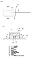
ここで、上述した保護カバーの施工例について、従来例を図5に基づいて説明する。この保護カバー1は、蒸発管2のメタル温度測定面にパット型熱電対10を溶接により固定した後、その周囲に耐熱テープ3を多重巻きして適所を針金4で固縛する。こうして固定した耐熱テープ3の外周側にセラミックス材質の溶剤5を塗布することにより、パッド型熱電対10の保護カバー1が完成する。
The evaporation pipe disposed in the boiler is heated and vaporized by a fluid such as water flowing in the pipe when a high-temperature combustion gas passes therethrough. When measuring the metal temperature of the evaporation tube with a sheathed thermocouple in an atmosphere where the ambient temperature is high like this evaporator tube, as a measure to prevent the influence of radiant heat due to the high ambient temperature, It was necessary to attach a protective cover to the temperature sensor.
Here, the example of construction of the protective cover described above will be described with reference to FIG. In this protective cover 1, a pad-
パッド型熱電対10は、矩形状とした金属製のパッド11に設けた切欠部にシース熱電対12の感温部を挿入して保持される。すなわち、シース熱電対12の先端部に設けられている感温部は金属製のパッド11に保持され、接触または近傍に位置する蒸発管2のメタル温度を測定するようになっている。なお、パッド型熱電対10は、パッド11を蒸発管2のメタル温度測定面に溶接(図中の符号13)して固定される。
このような保護カバー1を設けることにより、メタル温度を測定するシース熱電対12が耐熱テープ3等により周囲の温度から遮断されて輻射熱等の熱影響を低減することができる。なお、輻射熱を考慮する必要のない場合には、耐熱テープ3等よりなる保護カバー1を外部に取り付けることなくパッド型熱電対10が露出した状態、すなわち一般的には「裸パッド」と呼ばれている保護カバーなしの状態で使用される。
The pad-
By providing such a protective cover 1, the
また、耐火物表面の温度を測定する場合、シース熱電対の先端を溶接して密着させることができる金属面とは異なり、温度測定対象面にばらつきなく密着させることは困難になるため、密着度合いのばらつきにより測定誤差が生じやすくなる。そこで、この問題を解決する従来技術として、金属パッドと耐火物表面との間に耐火物充填材を介在させて密着固定することにより、耐火物表面温度の測定誤差を解消する温度測定方法及び温度測定用熱電対が提案されている。(たとえば、特許文献1参照)
しかしながら、従来の保護カバーなしのパッド型熱電対(裸パッド)は、図4に示した実験結果のように、輻射熱の影響を十分に除去できてないという問題を有している。
ここで、図4の実験結果を得た実験方法を図3に基づいて簡単に説明すると、異なるパッド型熱電対の試験品T1〜T5をメタル温度測定対象面となる金属板6の上に設置し、下面側から図示しない電気コンロで加熱する。この加熱と同時に、試験品T1〜T5から所定の間隔を設けた上方では、バーナ7が往復移動しながら加熱して輻射熱を与え、この状態により各試験品毎の温度変化を測定する。
However, the conventional pad-type thermocouple (bare pad) without a protective cover has a problem that the influence of radiant heat cannot be sufficiently removed as in the experimental results shown in FIG.
Here, the experimental method for obtaining the experimental results of FIG. 4 will be briefly described with reference to FIG. 3. The test pieces T1 to T5 of different pad type thermocouples are installed on the
この結果、保護カバー1を設けていない従来品の実験結果では、輻射熱による測定値の影響(Δt5)が大きいだけでなく、バーナ7による輻射熱の影響も往復移動の周期と一致する波線状となって現れている。また、輻射熱対策として保護カバー1を多重巻きにした図5の従来品では、保護カバー1の巻き付けを現場で施工する必要があるので、現地施工に多くの時間を要するという問題がある。
このように、従来の保護カバー1を設けたパッド型熱電対10は、現地施工に手間がかかるという問題を抱えているため、輻射熱の影響を低減してメタル温度測定対象面の温度を正確に測定できるだけでなく、現地施工の容易なパッド型熱電対の開発が望まれる。
本発明は、上記の事情に鑑みてなされたものであり、その目的とするところは、輻射熱の影響をより一層低減してメタル温度測定対象面の温度を正確に測定できる現地施工の容易なパッド型熱電対を提供することにある。
As a result, in the experimental result of the conventional product in which the protective cover 1 is not provided, not only the influence (Δt5) of the measurement value due to the radiant heat is large, but also the influence of the radiant heat due to the
As described above, the pad-
The present invention has been made in view of the above circumstances, and its object is to easily reduce the influence of radiant heat and to accurately measure the temperature of the metal temperature measurement target surface. Is to provide a thermocouple type.
本発明は、上記の課題を解決するため、下記の手段を採用した。
本発明は、温度測定を行うシース熱電対と、該シース熱電対の感温部周辺を保持して温度測定対象面に取り付けられるパッド部材とを具備し、前記温度測定対象面に輻射熱を受ける環境で使用されるパッド型熱電対であって、前記パッド部材が、前記温度測定対象面側に開口する感温部設置部と、前記感温部を前記輻射熱から遮温するように配設された低熱伝導材充填部とを備えていることを特徴とするものである。
In order to solve the above problems, the present invention employs the following means.
The present invention includes a sheath thermocouple that performs temperature measurement, and a pad member that is attached to the surface of the temperature measurement object while holding the periphery of the temperature sensing portion of the sheath thermocouple, and receives an radiant heat on the surface of the temperature measurement object In the pad type thermocouple used in the above, the pad member is disposed so as to shield the temperature sensing part from the radiant heat, and a temperature sensing part installation part opening on the temperature measurement target surface side. And a low thermal conductive material filling portion.
このようなパッド型熱電対によれば、パッド部材が、温度測定対象面側に開口する感温部設置部と、感温部を輻射熱から遮温するように配設された低熱伝導材充填部とを備えているので、低熱伝導材(断熱材)充填部が感温部に作用する周囲からの輻射熱を遮断し、感温部を温度測定対象面の近傍に接触させて、あるいは、温度測定対象面に直接接触させて表面温度を測定することができる。また、本発明のパッド型熱電対は、パッド部材に熱電対及び低熱伝導材が一体化されているので、着脱等の取り扱いも容易になる。 According to such a pad-type thermocouple, the pad member has a temperature-sensing part installation part that opens to the temperature measurement target surface side, and a low thermal conductive material filling part that is disposed so as to shield the temperature-sensing part from radiation heat. Therefore, the low heat conductive material (heat insulating material) filling part blocks the radiant heat from the surroundings that acts on the temperature sensing part, and the temperature sensing part is brought into contact with the vicinity of the surface to be measured, or the temperature is measured. The surface temperature can be measured in direct contact with the target surface. Moreover, since the pad type thermocouple of the present invention has a thermocouple and a low thermal conductive material integrated with the pad member, handling such as attachment and detachment becomes easy.
上述した本発明のパッド型熱電対によれば、熱電対の感温部が周囲の環境から受ける輻射熱の影響を最小限に抑えることができるので、たとえばボイラにおける蒸発管のように輻射熱の影響を受ける高温の環境下であっても、温度測定対象面の温度を正確に測定することができる。また、パッド部材に熱電対及び低熱伝導材が一体化されて着脱等の取り扱いを容易にしたので、現地施工の作業時間を短縮することができる。 According to the pad-type thermocouple of the present invention described above, since the temperature-sensitive part of the thermocouple can minimize the influence of radiant heat received from the surrounding environment, the influence of radiant heat, such as an evaporator tube in a boiler, can be suppressed. Even under a high temperature environment, the temperature of the temperature measurement target surface can be accurately measured. In addition, since the thermocouple and the low thermal conductive material are integrated with the pad member to facilitate handling such as attachment and detachment, the work time for on-site construction can be shortened.
以下、本発明に係るパッド型熱電対の一実施形態を図面に基づいて説明する。
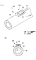
図1に示すパッド型熱電対20は、温度測定対象面に輻射熱を受ける環境、たとえば高温の燃焼ガスが流れるボイラ内において、蒸発管のメタル温度(表面温度)を測定するために使用される。このパッド型熱電対20は、温度測定を行うシース熱電対21と、このシース熱電対21の感温部22周辺を保持し、温度測定対象面となるメタル表面30に溶接等により固定して取り付けられるパッド部材23とを具備して構成される。
Hereinafter, an embodiment of a pad type thermocouple according to the present invention will be described with reference to the drawings.
The pad-
パッド部材23は略直方体形状とした金属製(たとえばSUS304)の部材であり、略平板のメタル表面30側に開口する感温部設置部(以下、「設置部」と呼ぶ)25と、感温部22を輻射熱から遮温するように配設された低熱伝導材充填部(以下、「充填部」と呼ぶ)26とを備えている。
略直方体形状のパッド部材23は、内部に充填部26となる空間が形成され、一面に設けた開口面は、低熱伝導材27を充填した後、同様の金属製とした蓋材24を溶接して閉じられる。また、パッド部材23には、充填部26となる空間の一面に、設置部25となる貫通溝が形成されている。図示の例では、蓋材24と設置部25となる貫通溝とが、充填部26となる空間の対向面に配置されている。
The
The substantially rectangular
すなわち、パッド型熱電対20は、先端に感温部22を備えたシース熱電対21と、設置部(貫通溝)25及び充填部(空間)26を備えたパッド部材23と、パッド部材23の充填部26を閉じる蓋材24と、充填部26に充填される低熱伝導材27とを備え、メタル表面30側となる設置部25を除く感温部22の周囲を、断熱材として機能する低熱伝導材27で覆って一体化した構成とされる。なお、低熱伝導材27としては、たとえばカオウール(登録商標)等が好適である。
このように構成されたパッド型熱電対20は、メタル表面30に対し、設置部25の貫通溝がメタル表面30側となるように溶接部28で固定設置される。
That is, the pad-
The pad-
この結果、シース熱電対21の感温部22の周囲は、設置部25の貫通溝を除きパッド部材23、蓋部材24及び低熱伝導材27により覆われるので、高温の燃焼ガス(図中の矢印G)が流れるボイラ内のような環境にあっても、感温部22に周囲の熱影響が及ぶのを最小限に抑え、かつ、燃焼ガスに含まれる灰等の粒子により感温部22が摩耗するのを防止することもできる。
図4は、上述したパッド型熱電対20について、輻射熱の影響を実験により確認した結果を示したものである。なお、この実験結果は、5種類の試作品T1〜5を用意し、上述した図3に示す方法により行った実験により得られたものである。
As a result, the periphery of the temperature sensing
FIG. 4 shows the result of confirming the influence of radiant heat by experiments for the
図4に示す実験結果において、試作品1は充填部26の空間に何も充填しないで中空としたもの、試作品2は充填部26の空間に木(カーボン)を充填したもの、試作品3は充填部26の空間にカオウール(登録商標)を充填したもの、試作品4は充填部26の空間に耐熱テープ3を折り畳んで重ねた耐熱テープ多重層を充填したもの、そして、試作品5は保護カバーなしの従来品である。
この実験結果によれば、バーナ7に点火して試作品1〜5の上方を往復移動させ、間接的に加熱したことによる熱影響、すなわち輻射熱の影響は、上述した本発明のパッド型熱電対20に相当する試作品3のΔt3が最も小さくなっている。従って、本発明のパッド型熱電対20が輻射熱の影響防止に有効であり、メタル表面30の表面温度を正確に測定できることが分かる。
In the experimental results shown in FIG. 4, the prototype 1 is hollow without filling the space of the
According to this experimental result, the thermal effect caused by indirect heating by igniting the
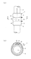
また、上述した実施形態では、メタル表面30を略平面としたが、比較的小径の蒸発管等のメタル温度を測定する場合には、メタル表面30′が曲面となるため、図2に示した変形例のパッド型熱電対20Aのように、メタル曲面30′に沿って金属材料を湾曲させた形状のパッド部材23′及び蓋部材24′となる。
このように、本発明のパッド型熱電対20,20Aは、シース熱電対21の感温部22を固定しているパッド部材23,23′の内部をくり抜いた空間部に断熱材として機能する低熱伝導材27を充填し、周囲からの温度を遮断して正確なメタル温度の測定を可能にしたものである。すなわち、本発明のパッド型熱電対20,20Aは、熱電対21の感温部22をメタル表面(蒸発管表面)30,30′に直接、あるいは、メタル表面30,30′に近いパッド部材23、23′の面に接触させ、このような接触面を除いて感温部22を低熱伝導材27により覆うことで、背面及び周囲からの温度吸収を小さくする構造となっている。
In the above-described embodiment, the
As described above, the pad-
従って、本発明のパッド型熱電対20,20Aによれば、シース熱電対21の感温部22が周囲の環境から受ける輻射熱の影響を最小限に抑えることができるので、たとえばボイラにおける蒸発管のように輻射熱の影響を受ける高温の環境下であっても、温度測定対象面となるメタル温度を正確に測定することができる。
なお、本発明は上述した実施形態に限定されるものではなく、本発明の要旨を逸脱しない範囲内において適宜変更することができる。
Therefore, according to the pad-
In addition, this invention is not limited to embodiment mentioned above, In the range which does not deviate from the summary of this invention, it can change suitably.
20,20A パッド型熱電対
21 シース熱電対
22 感温部
23,23′ パッド部材
24,24′ 蓋部材
25 感温部設置部
26 低熱伝導材充填部
27 低熱伝導材
28 溶接部
30 メタル表面(温度測定対象面)
20, 20A
Claims (1)
前記パッド部材が、前記温度測定対象面側に開口する感温部設置部と、前記感温部を前記輻射熱から遮温するように配設された低熱伝導材充填部とを備えていることを特徴とするパッド型熱電対。 A sheath thermocouple that performs temperature measurement, and a pad member that holds the periphery of the temperature sensing portion of the sheath thermocouple and is attached to the temperature measurement target surface, and is used in an environment that receives radiant heat on the temperature measurement target surface A pad-type thermocouple,
The pad member includes a temperature sensing part installation part that opens to the temperature measurement target surface side, and a low thermal conductive material filling part that is disposed so as to shield the temperature sensing part from the radiant heat. Features a pad-type thermocouple.
Priority Applications (1)
| Application Number | Priority Date | Filing Date | Title |
|---|---|---|---|
| JP2005054295A JP2006242574A (en) | 2005-02-28 | 2005-02-28 | Pad type thermocouple |
Applications Claiming Priority (1)
| Application Number | Priority Date | Filing Date | Title |
|---|---|---|---|
| JP2005054295A JP2006242574A (en) | 2005-02-28 | 2005-02-28 | Pad type thermocouple |
Publications (1)
| Publication Number | Publication Date |
|---|---|
| JP2006242574A true JP2006242574A (en) | 2006-09-14 |
Family
ID=37049155
Family Applications (1)
| Application Number | Title | Priority Date | Filing Date |
|---|---|---|---|
| JP2005054295A Withdrawn JP2006242574A (en) | 2005-02-28 | 2005-02-28 | Pad type thermocouple |
Country Status (1)
| Country | Link |
|---|---|
| JP (1) | JP2006242574A (en) |
Cited By (4)
| Publication number | Priority date | Publication date | Assignee | Title |
|---|---|---|---|---|
| CN101858793A (en) * | 2010-05-22 | 2010-10-13 | 东方电气集团东方汽轮机有限公司 | Narrow gap weld seam temperature measuring device and method |
| CN102692279A (en) * | 2011-03-21 | 2012-09-26 | 江苏亚星锚链股份有限公司 | Method for determining temperature uniformity of R5-grade mooring chain in heat treatment furnace |
| CN105157864A (en) * | 2015-10-13 | 2015-12-16 | 北京航空航天大学 | Hollow round bar specimen inner wall temperature measuring method |
| WO2022263022A1 (en) * | 2021-06-16 | 2022-12-22 | Tdk Electronics Ag | Assembly to protect a sensing device |
-
2005
- 2005-02-28 JP JP2005054295A patent/JP2006242574A/en not_active Withdrawn
Cited By (4)
| Publication number | Priority date | Publication date | Assignee | Title |
|---|---|---|---|---|
| CN101858793A (en) * | 2010-05-22 | 2010-10-13 | 东方电气集团东方汽轮机有限公司 | Narrow gap weld seam temperature measuring device and method |
| CN102692279A (en) * | 2011-03-21 | 2012-09-26 | 江苏亚星锚链股份有限公司 | Method for determining temperature uniformity of R5-grade mooring chain in heat treatment furnace |
| CN105157864A (en) * | 2015-10-13 | 2015-12-16 | 北京航空航天大学 | Hollow round bar specimen inner wall temperature measuring method |
| WO2022263022A1 (en) * | 2021-06-16 | 2022-12-22 | Tdk Electronics Ag | Assembly to protect a sensing device |
Similar Documents
| Publication | Publication Date | Title |
|---|---|---|
| CN104698025B (en) | Thermogravimetric measuring device | |
| US11415466B2 (en) | Temperature measuring device and method for determining temperature | |
| RU2567095C2 (en) | Infrared measurement of temperature, and its stabilisation | |
| EP2139295A1 (en) | Flexible heater comprising a temperature sensor at least partially embedded within | |
| JP6462710B2 (en) | Gas analyzer | |
| JPH10227703A (en) | Heat flux meter | |
| JP5872582B2 (en) | Temperature sensors and equipment | |
| JPH0933358A (en) | Device that measures temperature of high-temperature wall | |
| JP2006242574A (en) | Pad type thermocouple | |
| JP5959111B2 (en) | Heat flow sensor | |
| JP2022525074A (en) | Improved temperature sensor for gas burner and assembly consisting of the temperature sensor and burner | |
| JP2017173209A (en) | Specimen container and thermal analysis device | |
| RU2007125086A (en) | DEVICE FOR MEASURING THE INTENSITY OF RADIUS FLOWS DURING HEAT AND VACUUM TESTS OF SPACE VEHICLES AND METHOD OF ITS OPERATION | |
| US9816865B2 (en) | System and method for remote temperature measurements in a harsh environment | |
| Diller et al. | Heat flux measurement | |
| Northover et al. | A heat flux meter for use in boiler furnaces | |
| US20220397438A1 (en) | Non-invasive thermometer | |
| JPS61296229A (en) | Thermocouple and method for mounting the same | |
| Straubinger et al. | Simulation of reflow-based heat transfer on different thermocouple constructions | |
| JP6097197B2 (en) | Calorimeter and calorie measuring method | |
| KR101934839B1 (en) | Flow Reactor temperature measurement system using Quartz material | |
| US20220283105A1 (en) | Measurement of coating thermal properties by induction radiometry | |
| JP2752216B2 (en) | Thermocouple device | |
| JP3539624B2 (en) | Thermal conductivity measuring method and measuring device | |
| JP7075379B2 (en) | Heat history evaluation method for heat-resistant members and heat history evaluation device |
Legal Events
| Date | Code | Title | Description |
|---|---|---|---|
| A300 | Withdrawal of application because of no request for examination |
Free format text: JAPANESE INTERMEDIATE CODE: A300 Effective date: 20080513 |