JP2006242375A - Fluid coupling provided with holding ring having duplex functions - Google Patents
Fluid coupling provided with holding ring having duplex functions Download PDFInfo
- Publication number
- JP2006242375A JP2006242375A JP2005351996A JP2005351996A JP2006242375A JP 2006242375 A JP2006242375 A JP 2006242375A JP 2005351996 A JP2005351996 A JP 2005351996A JP 2005351996 A JP2005351996 A JP 2005351996A JP 2006242375 A JP2006242375 A JP 2006242375A
- Authority
- JP
- Japan
- Prior art keywords
- carrier
- fluid coupling
- extending
- bore
- finger
- Prior art date
- Legal status (The legal status is an assumption and is not a legal conclusion. Google has not performed a legal analysis and makes no representation as to the accuracy of the status listed.)
- Withdrawn
Links
- 239000012530 fluid Substances 0.000 title claims abstract description 88
- 230000008878 coupling Effects 0.000 title claims abstract description 59
- 238000010168 coupling process Methods 0.000 title claims abstract description 59
- 238000005859 coupling reaction Methods 0.000 title claims abstract description 59
- 238000000465 moulding Methods 0.000 claims description 4
- 238000007789 sealing Methods 0.000 claims description 4
- 239000007787 solid Substances 0.000 claims description 4
- 239000000463 material Substances 0.000 abstract description 20
- 230000007704 transition Effects 0.000 description 15
- 238000003780 insertion Methods 0.000 description 9
- 230000037431 insertion Effects 0.000 description 9
- 229920003023 plastic Polymers 0.000 description 7
- 239000004033 plastic Substances 0.000 description 7
- 238000000034 method Methods 0.000 description 5
- 238000002844 melting Methods 0.000 description 4
- 230000008018 melting Effects 0.000 description 4
- 239000002184 metal Substances 0.000 description 4
- 208000034693 Laceration Diseases 0.000 description 2
- 238000005452 bending Methods 0.000 description 2
- 229920003020 cross-linked polyethylene Polymers 0.000 description 2
- 239000004703 cross-linked polyethylene Substances 0.000 description 2
- 230000009977 dual effect Effects 0.000 description 2
- 238000013459 approach Methods 0.000 description 1
- 230000002950 deficient Effects 0.000 description 1
- 230000001788 irregular Effects 0.000 description 1
- 230000002093 peripheral effect Effects 0.000 description 1
- 238000007790 scraping Methods 0.000 description 1
- 238000006748 scratching Methods 0.000 description 1
- 230000002393 scratching effect Effects 0.000 description 1
- 238000000926 separation method Methods 0.000 description 1
- 238000003466 welding Methods 0.000 description 1
Images


Classifications
-
- F—MECHANICAL ENGINEERING; LIGHTING; HEATING; WEAPONS; BLASTING
- F16—ENGINEERING ELEMENTS AND UNITS; GENERAL MEASURES FOR PRODUCING AND MAINTAINING EFFECTIVE FUNCTIONING OF MACHINES OR INSTALLATIONS; THERMAL INSULATION IN GENERAL
- F16L—PIPES; JOINTS OR FITTINGS FOR PIPES; SUPPORTS FOR PIPES, CABLES OR PROTECTIVE TUBING; MEANS FOR THERMAL INSULATION IN GENERAL
- F16L37/00—Couplings of the quick-acting type
- F16L37/08—Couplings of the quick-acting type in which the connection between abutting or axially overlapping ends is maintained by locking members
- F16L37/084—Couplings of the quick-acting type in which the connection between abutting or axially overlapping ends is maintained by locking members combined with automatic locking
- F16L37/091—Couplings of the quick-acting type in which the connection between abutting or axially overlapping ends is maintained by locking members combined with automatic locking by means of a ring provided with teeth or fingers
Abstract
Description
本発明は、一般に、流体運搬部品を接合するために、流体カップリングに関する。 The present invention relates generally to fluid couplings for joining fluid carrying components.
金属またはプラスチックのチューブを互いに相互接続させるために、流体接続部、即ち、カップリングが公知である。こうしたチューブの1つは、また、弁、マニホルド、ポンプなどのような流体動作部品であってよい。 In order to interconnect metal or plastic tubes together, fluid connections, i.e. couplings, are known. One such tube may also be a fluid motion component such as a valve, manifold, pump, or the like.
このような流体コネクタは、典型的には、チューブの平坦な一定の直径の先端部と噛合う、径方向内方に延びた可撓性のばね状の指部を備えたリングの形態のリテイナを使用している。指部によって、チューブから離れるように指部を曲げるように挿入されて指部の内面と係合する解放ツールを用いて、チューブを取り除くことができる。 Such a fluid connector is typically a retainer in the form of a ring with a radially inwardly extending flexible spring-like finger that mates with the flat constant diameter tip of the tube. Is used. With the finger, the tube can be removed using a release tool that is inserted to bend the finger away from the tube and engage the inner surface of the finger.
PEX(交差結合されたポリエチレン)のようなより柔らかいプラスチックのチューブの使用により、流体カップリングを構成する際に考慮しなくてはならない他の要因を取り入れることができる。これらの擦り傷は、チューブに装着されたシール部材あるいはO−リングを通る漏れ通路を形成することがあり、あるいは、シール部材を損傷することもあり、流体漏れ通路の形成および欠陥流体カップリングの製造を招く。 The use of softer plastic tubing, such as PEX (cross-linked polyethylene), can incorporate other factors that must be considered when constructing fluid couplings. These scratches may form a leak passage through the seal member or O-ring attached to the tube, or may damage the seal member, creating a fluid leak passage and producing a defective fluid coupling. Invite.
上述したタイプの流体カップリングでは、シール部材およびリテイナが流体使用部品かハウジング内に装着された後、カップリングの端部フランジは、同じ溶融温度の同じ材料、即ち、互いに接着するプラスチックの使用を強要するソニックあるいは熱溶接によって、流体使用部品かハウジング着脱不可能に接合される。 In fluid couplings of the type described above, after the seal member and retainer are installed in the fluid-using part or housing, the end flange of the coupling uses the same material at the same melting temperature, i.e., plastic that adheres to each other. The parts using the fluid or the housing are joined in a non-detachable manner by forced sonic or thermal welding.
チューブの上面の擦り傷が流体カップリングのシール部材に損傷を与えるのを防ぎながら、管材あるいはチューブと流体使用部材即ちハウジングとの間の流体密接続を形成する流体カップリングを提供することが好ましいだろう。また、全てのコネクタ部品が流体使用部品即ちハウジングから取り外され得るような流体カップリングを提供することが望ましいだろう。また、異なる溶融温度を有する非制限的な数の異なる材料が使用可能であるような、ソニックあるいは熱溶接性のための同じ溶融点を有する同じ材料の使用を必要としない流体カップリングを提供することが望ましいだろう。 It would be desirable to provide a fluid coupling that forms a fluid tight connection between the tubing or tube and the fluid use member or housing while preventing scratching of the top surface of the tube from damaging the seal member of the fluid coupling. Let's go. It would also be desirable to provide a fluid coupling in which all connector parts can be removed from the fluid use part or housing. It also provides a fluid coupling that does not require the use of the same material with the same melting point for sonic or thermal weldability, such that an unlimited number of different materials with different melting temperatures can be used. It would be desirable.
本発明は、導管、弁、ポンプなどの2つの流体使用あるいは流体動作部材を接合するために、流体カップリングである。 The present invention is a fluid coupling for joining two fluid use or fluid working members such as a conduit, valve, pump and the like.
1つの態様では、流体カップリングは、開口端から延びたボアを備えた流体使用部品を有している。このボアは、内面を有している。キャリアは、第1の端面と第2の端面との間に延びたボアを有している。少なくとも1つの孔が、ボアに交差するキャリア内に形成されている。保持リングが、キャリアに装着されており、孔を通ってキャリアのボア中へと延びた先端部を備えた少なくとも1つの内方に延びた指部と、キャリアから外方に延びた先端部を備えた少なくとも1つの外方に延びた指部とを有している。外方に延びた指部の先端部は、キャリアを流体使用部材に固定するために流体使用部材内でボアの内面と係合する。保持リングで内方に延びた指部の先端部は、管材をキャリアに固定するように管材と係合する。 In one aspect, the fluid coupling includes a fluid use component with a bore extending from the open end. The bore has an inner surface. The carrier has a bore extending between the first end face and the second end face. At least one hole is formed in the carrier that intersects the bore. A retaining ring is attached to the carrier and has at least one inwardly extending finger with a tip extending through the hole into the carrier bore and a tip extending outwardly from the carrier. And at least one outwardly extending finger. The tip of the outwardly extending finger engages the inner surface of the bore within the fluid use member to secure the carrier to the fluid use member. The tip of the finger that extends inwardly with the retaining ring engages the tubing to secure the tubing to the carrier.
内側および外側シールが、キャリアに配置されている。これらシールは、別個のO−リングであってよく、あるいは、2段成型処理によってキャリアと共にキャリア上で一体的に運搬されてもよい。 Inner and outer seals are disposed on the carrier. These seals may be separate O-rings or may be carried together on the carrier with the carrier by a two-step molding process.
キャリアによって管材がキャリア内のボア中に挿入されるように管材を流体使用部材にシールする内側シールが、内方に延びた指部が接触する管材の所定の使用部分がシール部材と接触しないように、保持リングで内方に延びた指部の先端部から軸方向に配置されている。 The inner seal that seals the tubing to the fluid use member so that the tubing is inserted into the bore in the carrier by the carrier so that the predetermined use portion of the tubing contacted by the inwardly extending fingers does not contact the seal member Further, it is arranged in the axial direction from the tip end portion of the finger portion extending inward by the holding ring.
他の態様では、複数の内方に延びた指部あるいは複数の外方に延びた指部に、保持リングの外周の周りで指部の長さを螺旋形に変えることによって、螺旋形のピッチが形成されている。これにより、内方に延びた指部に螺旋形のピッチが形成される場合は、管材が、接合されたキャリアとハウジングとから外され得る。外方に延びた指部に螺旋形のピッチが形成される場合は、キャリアと管材との全体が、ハウジングから外され得る。 In another aspect, the helical pitch is changed by spiraling the length of the fingers around the outer periphery of the retaining ring into a plurality of inwardly extending fingers or a plurality of outwardly extending fingers. Is formed. Thereby, when a helical pitch is formed on the inwardly extending fingers, the tube can be removed from the joined carrier and housing. If a helical pitch is formed on the outwardly extending fingers, the entire carrier and tubing can be removed from the housing.
本発明の流体カップリングは、管材かチューブをコネクタに接合させるだけでなくコネクタ部品を流体使用部品か外側ハウジングに着脱可能に接合させるようにも、同じリテイナを使用することにより、既存の流体カップリングを改良している。本発明の流体カップリングのコネクタ部品は、また、2つの異なる方法で組立可能である。その方法の1つは、管材をハウジング中に挿入する前、あるいは管材をハウジング中に接合挿入させる前に、流体使用部品あるいはハウジング中に固定および挿入することである。 The fluid coupling of the present invention is not limited to connecting a pipe or tube to a connector, but also to connect a connector part to a fluid-using part or an outer housing in a detachable manner by using the same retainer. The ring has been improved. The connector part of the fluid coupling of the present invention can also be assembled in two different ways. One way is to fix and insert the tubing into the fluid-using component or housing before inserting the tubing into the housing or joining the tubing into the housing.
本発明の流体カップリングは、また、管材挿入中か取外し中にリテイナによって管材の面に形成されることのある擦り傷がシール部材に接触したり、シール部材を損傷したり、さもなければシール部材を通る漏れ通路を形成することのないようにシール部材をリテイナから軸方向に離間させる。本発明の流体カップリングは、また、コネクタ部品全体を流体使用部材即ちハウジングから容易に取り外せるようにする構造を有している。 The fluid coupling according to the present invention may also cause a scratch that may be formed on the surface of the pipe member by the retainer during insertion or removal of the pipe member to contact the seal member, damage the seal member, or otherwise the seal member. The seal member is axially spaced from the retainer so as not to form a leak passage through the retainer. The fluid coupling of the present invention also has a structure that allows the entire connector component to be easily removed from the fluid use member or housing.
本発明の様々の特徴、利点、および他の利用が、以下の詳細な説明および図面を参照することによって明らかになるだろう。 Various features, advantages, and other uses of the invention will become apparent by reference to the following detailed description and drawings.
後で更に詳しく説明されるように、流体カップリングは、管材と流体使用部材のような2つの部品の間に形成されている。流体使用部材は、所定の流体運搬か流体動作部材であってよく、チューブ、導管、貫通孔を有するハウジング、管材、弁、ポンプ、およびマニホルドなどであってもよい。 As will be described in more detail later, the fluid coupling is formed between two parts, such as a tube and a fluid use member. The fluid use member may be a predetermined fluid carrying or fluid operating member, and may be a tube, a conduit, a housing having a through hole, a pipe, a valve, a pump, a manifold, and the like.
管材は、開口端から延びた典型的には貫通孔を有するチューブ部材か流体使用部材の幾何学か形状として規定されている。「管材」として規定されるチューブ部材の幾何学あるいは形状は、一定の平坦な直径を有するのではなく不規則な形状および外形を有するチューブの端部と同様に、直線、丸いチューブの端部のような平坦で一定の直径を有する端部を含む所定の幾何学か形状を有することを意図されている。 Tubing is defined as the geometry or shape of a tube member or fluid use member that typically has a through hole extending from the open end. The geometry or shape of a tube member, defined as “tube”, is similar to the end of a straight, round tube, as well as the end of a tube having an irregular shape and profile rather than having a constant flat diameter. It is intended to have a predetermined geometry or shape that includes such a flat, constant diameter end.
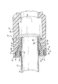
図1および図2に示されているように、流体カップリング20は、流体的におよびシールするように、管材22を流体使用部材(後ほどハウジング24と規定する)に結合させる。管材22は、開口端28から延びたボア26を有していて管状かつ円筒形である。管材22は、金属、プラスチックなどの所定の適当な材料で形成可能である。 As shown in FIGS. 1 and 2, fluid coupling 20 couples tubing 22 to a fluid use member (later defined as housing 24) to fluidly and seal. The tube 22 has a bore 26 extending from the open end 28 and is tubular and cylindrical. The tube material 22 can be formed of a predetermined appropriate material such as metal or plastic.
ハウジング24はまた、第1の開口端面30を有している。ボア32が、第1の端面30からハウジング24を通って延びている。ボア32は、例えば、第1の端面30から延びた第1の大きな直径のボア34と、この第1のボア34から軸方向に延びた第2の比較的小さな直径のボア36と、この第2のボア36から軸方向に延びた第3のボア38と、この第3のボア38から軸方向に延びた第4のボア40とから成る段付きボアとして形成されている。第5のボア42が、例えば、第4のボア40から延びる形で図1に示されている。 The housing 24 also has a first open end face 30. A bore 32 extends from the first end surface 30 through the housing 24. The bore 32 includes, for example, a first large diameter bore 34 extending from the first end face 30, a second relatively small diameter bore 36 extending axially from the first bore 34, and the first The second bore 36 is formed as a stepped bore including a third bore 38 extending in the axial direction from the second bore 36 and a fourth bore 40 extending in the axial direction from the third bore 38. A fifth bore 42 is shown in FIG. 1 as extending from, for example, the fourth bore 40.
第1のボア34と第2のボア36とは、概してハウジング24の外面46から垂直方向に延びた肩部の形の面44によって分離されている。 The first bore 34 and the second bore 36 are separated by a generally shoulder-shaped surface 44 that extends vertically from the outer surface 46 of the housing 24.
第2のボア36と第3のボア38とは、夫々に、面48によって分離されている。この態様では、面48は、外面46あるいはハウジング24の長軸に対して傾斜されているか角を成している面として規定している。 The second bore 36 and the third bore 38 are each separated by a surface 48. In this embodiment, the surface 48 is defined as a surface that is inclined or angled with respect to the outer surface 46 or the major axis of the housing 24.
第3のボア38および第4のボア40は、夫々に、同様に、ハウジング24の外面46あるいは長軸に対して角を成しているか傾斜された面50によって分離されている。 The third bore 38 and the fourth bore 40 are similarly separated by an outer surface 46 of the housing 24 or a surface 50 that is angled or inclined with respect to the major axis.
角を成しているか傾斜されている面48、50は、後述される保持リングあるいはリテイナの指部用の支持面を規定している。 The angled or inclined surfaces 48, 50 define a support surface for the retaining ring or retainer fingers described below.
図1および図2に示され、図3ないし図5にさらに詳しく示されているように、流体かプリング20はまた、ワンピースのモールド成形か機械加工されたボディ62の形態などのキャリア60を有している。ボディ62は、金属、プラスチックなどの適当な材料で形成可能である。
As shown in FIGS. 1 and 2 and in more detail in FIGS. 3-5, the fluid or pulling 20 also has a
ボディ62は、第1の端面64と、対向した第2の端面66とを有している。ボア68は、第1の端面64と第2の端面66との間に延びている。ボディ62の外面は、例えば、第1の端面64に近接した端部フランジ70に形成された段付き構造を有している。肩部72は、フランジ70から径の減じられたリング74まで傾斜されているか該して垂直な移行部を規定している。リング74は、外側シール部材76用の座部を形成している。
The
例えばリング74の主面に対して垂直に延びている肩部78が、リング74と第2のリング80との間の移行部を形成している。
For example, a
概して円筒形であり一定の直径を有するスリーブ82は、移行面84によって第2のリング80に接続されている。スリーブ82は、移行面84からボディ62の第2の端面66まで延びている。
A
移行面84は、スリーブ82の一端面から延びたほぼ垂直な壁86を有している。壁86の径方向外方の端面は、第2のリング80の一端面から延びた、傾斜されているか角度が付けられている面88に移行している。例えば3つの、複数のノッチ90が、移行面84に形成され、スリーブ82と第2のリング80との間に延びている。ノッチ90は、等距離で配置され、同じスペーシングを空けて、後述するように保持リングの外側の指部と同じ数だけ設けられている。ノッチ90は、保持リング上の外側の指部用の座部あるいは支持面を形成している。
The
複数の孔、例えば単なる例として3つの孔は、ボディ62の第1の端面64から延びた第1の直径のボア96と、この第1のボア96の一端面から垂直に延びている肩部100から軸方向に延びた第2のボア98と、このボア98の一端面から突出してほぼ垂直に延びている肩部104から延びた第3のボア102とから成る段付き構造を有している。
A plurality of holes, for example three holes by way of example, have a first diameter bore 96 extending from the
角をなした面94が、スリーブ82を通って形成され、各孔92の一部分を形成している。この面94は、後述するように、径方向内方に延びている指部のための支持面を形成している。
An
図3に示されているように、ボア68は、例えば、ボディ62の第1の端面64から延びた第1の直径のボア96と、この第1のボア96の一端面から垂直に延びた肩部100から軸方向に延びた第2のボア98と、このボア98の一端面から突出したほぼ垂直な肩部104から延びた第3のボア102とより形成された段付き構造を有している。
As shown in FIG. 3, the
肩部100と、ボア96の近接した内面とは、第2の内側シール部材106用の座部を形成している。図1〜図4に示され、図5に更に詳しく示されているように、リテイナ、即ち、保持リング110は、キャリアのボディ62に装着され、管材22をキャリア60に固定する機能と、キャリア60をハウジング24内に固定する機能との、2重の機能を果す。
The
適当な材料、典型的には金属か弾性およびばね特性を有する高強度プラスチックで形成可能な保持リング110は、図2〜4に示されているようにキャリアのボディ62のスリーブ82上に着座するような直径を有する環状バンド、即ち、リング112を有している。
A retaining
少なくとも1つあるいは複数の径方向内方および角張って延びたラッチ部材か指部が、バンド112から延びている。例えば、3つのラッチ指部114,116、および118が、バンド112の1つの端面から延びている。指部114,116、および118は、各孔92内の面94によって支持される。更に、各ラッチ指部114,116,および118は、内側端部を有している。全てが、概して、参照符号120で示されており、各孔92を通ってボア98中へ延びている。これにより、図1に示されているように第1の管材22と固定係合するために端部120が位置され得る。
Extending from the
キャリアボディ62のスリーブ82上での保持リング110のリング部112の組立中に、内側に延びたラッチ指部114,116、および118は、保持リング110が図1および図3に示されているように面86に当接するまで、スリーブ82の面に沿って外側に曲がっている。この時、内側ラッチ指部114,116、および118の先端部120は、孔92とアラインメントされ、図2ないし図6に示されているようなこれらの径方向内方に傾斜した通常の位置へと跳ね返る。これにより、各ラッチ指部114,116、および118の先端部120が、管材22の外面に対する干渉位置に付けられ得る。キャリアのボディ62中に管材22を挿入する間、ラッチ指部114,116、および118の先端部120が、管材22の外面と係合し、これを押し抜く。各ラッチ指部114,116、および118の径方向内方に延びた傾斜位置により、キャリアのボディ62から管材22を分離する方向への逆動が、内側ラッチ指部114,116、および118によって抵抗される。
During assembly of the
また、例えば、保持リング110が、複数の径方向外方に延びて傾斜したラッチ指部を有している。3つのラッチ指部122,124,126が、例として示されている。外側ラッチ指部112,124、および126は、内側ラッチ指部114,116、および118の及ぶ程度の径方向内方に延び傾斜した位置とは反対の径方向外方に延び傾斜した位置でバンド112の対向した側端部から延びている。
Further, for example, the holding
各外側ラッチ指部122,124、および126は、キャリアのボディ62の面90上に支持され、複数のノッチ90の1つの中に配置されている。このため、保持リング110がキャリアのボディ62上の所定位置に維持されることができ、内側指部114,116、および118がキャリアのボディ62の孔92中に挿入されるのと合わせて、保持リング110がキャリアのボディ62から回転および分離に抵抗する。
Each
図2〜図4に示されているように、各外側ラッチ指部122,124、および126は、ハウジング24内のボア36の内面との干渉位置に配置される外側先端部128を有している。このようにして、キャリア62がハウジング24の第1の開口端面30を通って挿入された時に、外側ラッチ指部122,124、および126の各々の先端部128が、ボア36の内面に係合し、押し抜く。外側ラッチ指部122、124、および126の各々の角位置が、キャリアのボディ62が挿入方向とは逆方向へと動くのに抵抗して、キャリア60をハウジング24内にしっかりと保持する。
As shown in FIGS. 2-4, each
内側ラッチ指部114,116、および118の各々は、ほぼ平坦な固体の部材で出来ている。外側ラッチ指部122,124、および126の各々は、複数の別個に移動可能な片持ち形状の指部として形成可能であることが、理解されるだろう。
Each of the
外側ラッチ指部122,124、および126の各々は、例えば、平坦な固体の部材より形成されている。各外側ラッチ122,124、および126は複数の別個に移動可能な片持ち形状の指部で形成可能であることが理解されるだろう。
Each of the
ハウジング24内の角を成しているか傾斜された面50がキャリアのボディ62に対向し、これに対して概して平行であることに、注意しなくてはならない。これにより、複数の内側ラッチ指部114,116、および118の内の1つのための開口が与えられる。同様に、ハウジング24内の角を成した面48は、キャリアボディ60の角を成しているか傾斜された面90に対向しているか、これに対して概して平行であり、外側ラッチ指部122,124、および126の内の1つのためのスロットを形成している。
It should be noted that the angled or inclined surface 50 in the housing 24 faces the
複数のシール部材は、キャリア60に形成され、即ち、配置され、キャリアをハウジング24と管材22に対してシールしている。シール部材は、例えば、外側シール部材72と内側シール部材106とを有している。外側シール部材72および内側シール部材106はキャリア60とは別個の部材として形成可能であるが、1つの態様では、内側シール部材72および外側シール部材106は、2段成型処理によってキャリアのボディ62と一体的にしっかりと結合可能である。これには、シール部材72,106が、キャリアボディ62を形成する材料のモールド成形温度に準拠した材料で形成されることが必要となってくる。
The plurality of sealing members are formed on the
内側シール部材72と外側シール部材106との各々には、例えば外側シール部材72のための葉130,132や、内側シール部材106のための葉134,136のような1つ以上の葉部が形成されている。
Each of the inner seal member 72 and the
外側シール部材72は、キャリアのボディ62の第1のリング面74上に着席する。内側シール部材106は、ボア96の内面に着席し、キャリアボディ62内の肩部100に当接する。
The outer seal member 72 is seated on the
流体カップリング20は、2つの異なる方法で組立可能である。両方法は、シール部材72,106がキャリアボディ62上に形成されるか配置されることから始まる。保持リング110はまた、上述したようにキャリアボディ62に装着されている。
The fluid coupling 20 can be assembled in two different ways. Both methods begin with the
第1の組立方法では、キャリアボディ62が、図2に示されているように、キャリアボディ62の肩部78がハウジング24内で肩部44に当接するまで、ハウジング24の開いた第1の端面30を通って挿入される。この時、外側ラッチ指部122,124、および126の先端部128が、キャリア60をハウジング24にしっかりとラッチ留めするように、ハウジング24のボア36の内面と係合し押し抜く。
In the first assembly method, the
このように挿入する間、外側シール部材72の葉部130,132が、キャリアボディ62をハウジング24に流体的にシールするように圧迫される。
During this insertion, the
次に、管材22の先端部は、図1に示されているように、キャリア60の開口端64を通って挿入される。このように挿入される間、先端部22の外面が、最初に内側シール部材106の葉部134,136とシールするように係合する。管材22の挿入は、第1の端部28が、内側ボア98の端部とボア102の開始部で肩部104に当接するまで続く。管材22の第1の端部28が肩部104に近づくにつれて、内側ラッチ指部114,116、および118の先端部120が、管材22の外面と係合し、これを押し抜く。
Next, the distal end portion of the tube material 22 is inserted through the
しかしながら、図2に示されているように、管材22の、第1の端部28に近接した端部のみが、内側ラッチ指部114,116、および118の先端部120と係合される。内側シール部材106と係合された管材22の面は、内側ラッチ指部114,116、および118と接触されることがなく、かくして、内側シール部材106の流体漏れや損傷につながる擦り傷、削り溝、あるいは面裂傷がつくことはないままである。
However, as shown in FIG. 2, only the end of the tubing 22 proximate the first end 28 is engaged with the
他の組立方法に関わって、キャリア60と、保持リング110と、内側および外側シール72,106とが、上述のように組立てられる。続いて、管材22の第1の端部28が、上述のように開いた第1の端面64を通ってキャリア60のボア68中に挿入される。内側ラッチ指部114,116、および118が、キャリア60を管材22の端部上に保持する。
In connection with other assembly methods, the
次に、組立てられた管材22およびキャリア60とが、ハウジング20の開いた第1の端面30を通ってユニットとして挿入される。ボア36,38、および46の異なる直径および傾斜面の夫々により、外側ラッチ指部122,124,および126の先端部128が、キャリア60がハウジング24のボア32中にほぼ完全に挿入されるまで、ボア36の内面と係合しない。この時、外側ラッチ指部122,124、および126の先端部128が、キャリア60および取付けられた管材22をハウジング24内に固定するように、ハウジング24のボア36の内面と係合する。
The assembled tube 22 and
外側シール部材72は、キャリア62上で外側ラッチ指部122,124、および126の先端部128から軸方向に離間され、外側シール部材72と係合されるボア34の擦り傷や面裂傷を防ぐように外側ラッチ指部122,124,および126と係合されるボア36よりも異なるボア34内に配置されていることに、注意すべきである。
The outer seal member 72 is axially spaced from the
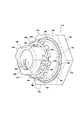
図6〜11を参照すると、ハウジングの形態である図11に示された流体使用部材152に対して、上述され図1〜3に示された管材22のような管材22を流体的にカップリングするために使用する他の態様の流体カップリング150が示されている。
Referring to FIGS. 6-11, the
この流体カップリング150は、キャリアボディ162、O−リング164のような外側シール部材、内側シール部材、即ち、O−リング166、リテイナ、即ち、保持リング168、およびトップハット170から成るキャリア160を有している。
The
キャリアボディ162は、モールド成形されたか機械加工されたプラスチックのワンピースボディであってよい。キャリアボディ162は、キャリアボディ162の第1の端面174から延びた端部フランジ172を有している。端部フランジ172の周面は、後述するようにキャリア162のハウジング152からの取外しを容易にするようにレンチかソケットを受けるために、ツール係合面を与える六角平面のような複数の平面176より形成可能である。
The
第1の環状リング178が、端部フランジ172の1つの端面から小径で突出している。第1のリング178は、第1の外側シール部材かO−リング164のための支持面か座部を形成している。
A first
肩部180が、第1のリング178よりも小さな直径を有する、第1のリング178と第2のリング182との間の移行部を形成している。
A
第2のリング182から垂直でない角度で配置された移行面184が、第2のリング182の1つの端面から延び、ほぼ垂直に延びた平面186へと移行している。ほぼ円筒形のスリーブ188が、平面186から軸方向に延びている。
A
複数の孔、例えば単なる例として3つの孔190,192、および194、即ち、窓は、平面186にほぼ近接して、スリーブ188内にこれを貫通するように形成されている。各孔、即ち、窓190,192、および194は、キャリアボディ162を通って延びた内部ボアへと開口している。
A plurality of holes, such as three
例えば3つのノッチ196,198,および200のような複数のノッチが、スリーブ188内に形成され、キャリアボディ162の第2の端面202から各孔190,192、および194まで夫々に延びている。各ノッチ196,198、および200は、小径部を形成し、保持リング168の内側ラッチ指部を方向付けて、保持リング168をスリーブ188上で挿入する間に通常の位置に弾性的に戻ろうとする本来の能力を超える内側ラッチ指部の過剰な曲げを防ぐように、窓190,192、および194の1つとアラインメントされる。
A plurality of notches, such as, for example, three
各ノッチ196,198、および200の前端面は、後述するように、リテイナ168をキャリアボディ162のスリーブ188上に設ける間にリテイナ168の内側ラッチ指部のための傾斜面を形成するように、キャリアボディ162の第2の端面202から角度をなしている。
The front end face of each
図10に示されているように、キャリアボディ162は、第1の端面174から延びた第1のボア210を有している。この第1のボア210は、ボア210から第2の小径部214までほぼ垂直に延びた肩部212で終端している。第2のボア214は、第1のボア210から同軸上に延び、キャリアボディ162を通って長軸に対してほぼ垂直な、角張った肩部216で終端している。
As shown in FIG. 10, the
肩部216は、端の肩部220まで延びた第3のボア218へと移行している。キャリアボディ162を通って長軸に対してほぼ垂直に配置されている端の肩部220は、キャリアボディ160の第2の端面202で第4のボア222中へ移行している。肩部220は、図10に仮想上示されている管材230の第1の挿入された端部を受けるために、挿入制限部か止め部を形成している。
The
肩部216は、内側シール部材、即ち、O−リング166のための座部を形成している。第2のボア214は、トップハット170のスリーブ232を摺動可能に受けるような大きさにされている。トップハット170のスリーブ232の一端部のフランジ234が、肩部212に当たって第1のボア210内に着席する。トップハット170は、第2のシール部材166をキャリアボディ160内に保持するように働く。
図6〜10に示されているように、リテイナ168は、中央リング240を有している。リテイナ168がキャリアボディ162のスリーブ188に装着されているとき、ほぼ平坦なリング240は、キャリアボディ162の平面188に当たって着席する。これにより、リング、即ち、バンド240の主面が斜めに、典型的にはキャリアボディ162の長軸に対して垂直方向に配置され、これによって、キャリアボディ162、管材230、およびハウジング152の間に保持リングによって与えられる引抜き抵抗が増す。
As shown in FIGS. 6-10, the
保持リング168はまた、参照符号242で各々が示された少なくとも1つ以上の内側ラッチ指部を有している。単なる例として、内側ラッチ指部は、均等に周方向に離間された3つのグループの内側ラッチ指部244,246、および248として配置されている。各内側ラッチ指部は、少なくとも1つの、典型的には1つ以上のラッチ指部であり、3つのラッチ指部242が各グループ244,246、および248を形成している。各グループ244,246、および248の各ラッチ指部242はまた、各グループ244,246、および248内で近接したラッチ指部242から均等に離間されている。
The retaining
ラッチ指部242は、キャリアボディ162のスリーブ188の孔190,192、および194を通って延び、管材230の外面との干渉位置に配置されるようにボア218の内面の径方向内方に突出した先端部250を有している。
The
保持リング180をスリーブ188上に挿入する間、ラッチ指部244,246、および248から成る各グループのラッチ指部242は、ノッチ196,198、および200の傾斜面に沿って摺動し、ラッチ指部244の先端部250が図10に示された通常の位置へ跳ね返され得るように保持リング168のリング240がスリーブ188上に十分に深く挿入されるまで、径方向外方に曲がる。
During insertion of retaining
保持リング168はまた、少なくとも1つ以上の外側ラッチ指部254を有している。単なる例として、複数のラッチ指部254は、リング240の全周の周りで均等に周方向に離間されている。外側ラッチ指部254は、内側ラッチ指部242のグループ244,246、および248と類似した周方向に離間されたグループで提供されるのに加えて、図6〜9に示されているのとほぼ同じ数だけ提供され得ることが、理解されるだろう。
The retaining
各外側ラッチ指部254は、保持リング268のリング240の一端部から径方向および角張って外方に配置された径方向外側先端部256で終端している。各外側ラッチ指部254の先端部256は、ハウジング152の内面に対する干渉位置に配置されている。
Each
ハウジング152は、例えば、第1の端面260と、対向した第2の端面262とを有している。ボア手段は、第1の端面260と第2の端面262との間に延びている。ボア手段は、周方向に延びた肩部266で終端した第1の端部260から延びた第1のボア264を有している。第2のボア268は、肩部266の径方向内方の端面からハウジング162を通って延びた長軸に対して傾斜しているか角をなした面270を形成する移行面へと延びている。第3のボア272は、移行面270から端の肩部274まで延びている。端の肩部274は、第4のボア276中へと移行する。
The
上述した第1の態様の流体カップリングと同様に、シール164,166を有するキャリアボディ160と、保持リング168と、トップハット170とは、事前組立の後、ハウジング252中へキャリア160および管材230を挿入する前に、管材230の端部に装着され得る。あるいは、キャリア260が、ハウジング152内に事前に装着され、次に、管材230が、キャリア160に挿入およびラッチ留めされ得る。
Similar to the fluid coupling of the first aspect described above, the
このような組立中に、外側の、即ち、第1のシール164は、キャリア160をハウジング162に対してシールするように、キャリア160の第1のリング178と、ハウジング152の離間された内部ボア164との間に着席する。第2のシール部材166は、肩部216およびキャリア160に当たって着席し、トップハット170によってキャリア160内に保持される。
During such assembly, the outer or
内側、即ち、第2のシール部材166は、管材230をキャリア160中へ挿入する方向に対して軸方向外方に離間されていることに、注意しなくてはならない。このように、内側ラッチ指部242の先端部250によって係合されて擦られる可能性のある管材230の外面の所定の部分は、第2のシール部材166の内面と接触しない。
It should be noted that the inner or
図10に示された組立位置では、リング240は、カップリング150の長軸に対してほぼ垂直に延びている。このため、リテイナ168が、キャリア160とハウジング152との間で、第1の態様の流体カップリング20の保持リング110のバンド112のほぼ水平な配置の場合よりも強く着席されるか設けられる。
In the assembled position shown in FIG. 10, the
他の態様では、内側ラッチ指部242か外側ラッチ指部254には、保持リング168の周りに螺旋形か渦巻形の構造が与えられ得る。これは、第1の最も短い内側ラッチ指部242あるいは外側ラッチ指部254から始まって最も長い内側ラッチ指部242あるいは外側ラッチ指部244までリテイナ168の円周の周りで各近接した内側ラッチ指部242あるいは外側ラッチ指部244の長さを徐々に増していくように各内側ラッチ指部244あるいは各外側ラッチ指部254の長さを変えることによって果され得る。これにより、内側ラッチ指部242の先端部250あるいは外側ラッチ指部254の先端部256が螺旋形に配置される。内側ラッチ指部242が長さ方向に螺旋形構造を有するように形成されている場合、管材230は、この管材230あるいは結合されたキャリア160およびハウジング152に回転ねじ解放(unthreading)力を加えることによって解放され、ハウジング152およびキャリア160を管材230から分離させることができる。
In other aspects, the
あるいは、外側ラッチ指部254が長さ方向に螺旋形の構造を有している場合、結合された管材230およびキャリア160は、アセンブリ一式としてハウジング152に対して解放され得る。
Alternatively, if the
最後に、単一保持リングが、キャリアを係合ハウジングあるいは流体部材にラッチ留めするだけでなく管材をキャリアにラッチ留めする2重の機能を果す独特の流体カップリングが開示されてきた。この単一保持リングにより、管材と急速接続部品とがソニックあるいは熱溶接されないため、急速接続部を形成してこの急速接続部を管材に結合させるのに、異なる溶融温度の異なる材料が使用可能である。 Finally, a unique fluid coupling has been disclosed in which a single retaining ring serves the dual function of latching tubing to the carrier as well as latching the carrier to the engagement housing or fluid member. Because this single retaining ring does not sonic or heat weld the tubing to the quick connect parts, different materials with different melting temperatures can be used to form the quick connect and join the quick connect to the pipe. is there.
62・・・ボディ、64・・・第1の端面、66・・・第2の端面、68・・・ボア、70・・・端部フランジ、72・・・肩部、74・・・リング、76・・・シール部材76、80・・・第2のリング、82・・・スリーブ。
62 ... Body, 64 ... First end surface, 66 ... Second end surface, 68 ... Bore, 70 ... End flange, 72 ... Shoulder, 74 ...
Claims (26)
第1の端面と第2の端面との間に延びたボアを有し、このボアを交差する少なくとも1つの孔が中に形成されているキャリアと、
前記キャリアに装着され、前記孔を通ってキャリアのボア中へと延びている先端部を備えた少なくとも1つの内側に延びた指部と、キャリアから外方に延びる先端部を備えた少なくとも1つの外側に延びた指部とを有し、このキャリアの外側に延びた指部の先端部は、キャリアを流体使用部材に固定させるように、前記流体使用部材のボアの内面と係合する保持リングとを具備し、
保持リングの前記内側に延びた指部の先端部は、管材をキャリアに固定させるように、管材と係合する、流体カップリング。 A fluid use member having a bore extending from the open end and having an inner surface;
A carrier having a bore extending between the first end face and the second end face and having at least one hole formed therein that intersects the bore;
At least one inwardly extending finger with a tip attached to the carrier and extending through the hole into the carrier bore and at least one with a tip extending outwardly from the carrier And a retaining ring that engages an inner surface of the bore of the fluid use member so that the carrier is secured to the fluid use member. And
A fluid coupling in which a tip of the finger extending inwardly of the retaining ring engages the tubing so that the tubing is secured to the carrier.
第1および第2の互いに対向した端部を有し、少なくとも1つの内側に延びた指部がこの第1の端部を延長させ、前記外方に延びた指部がこの第2の端部から延びている、平坦なバンドと、
前記キャリアの長軸に対してほぼ平行にキャリアに形成された平面とを有し、保持リングの前記バンドは、前記キャリアの平面に配置されている、請求項1の流体カップリング。 The retaining ring is
The first and second opposing ends have at least one inwardly extending finger extending the first end and the outwardly extending finger is the second end A flat band extending from the
The fluid coupling of claim 1, further comprising: a plane formed in the carrier substantially parallel to the major axis of the carrier, wherein the band of the retaining ring is disposed in the plane of the carrier.
第1および第2の周方向に互いに離間された端部を有し、前記少なくとも1つの内側に延びたラッチ指部はこの第1の端部から延び、前記少なくとも1つの外側に延びたラッチ指部は第2の端部から延びている、平坦なバンドと、
前記キャリアの長軸に対してほぼ垂直にキャリアに形成された平面とを有し、」保持リングの前記バンドは、キャリアの平面に配置されている、請求項1の流体
カップリング。 The retaining ring is
First and second circumferentially spaced ends, the at least one inwardly extending latching finger extends from the first end and the at least one outwardly extending latching finger A flat band extending from the second end; and
The fluid coupling of claim 1, wherein the band of the retaining ring is located in the plane of the carrier.
Applications Claiming Priority (1)
| Application Number | Priority Date | Filing Date | Title |
|---|---|---|---|
| US11/008,388 US7341286B2 (en) | 2004-12-09 | 2004-12-09 | Fluid coupling with dual function retention ring |
Publications (1)
| Publication Number | Publication Date |
|---|---|
| JP2006242375A true JP2006242375A (en) | 2006-09-14 |
Family
ID=36024318
Family Applications (1)
| Application Number | Title | Priority Date | Filing Date |
|---|---|---|---|
| JP2005351996A Withdrawn JP2006242375A (en) | 2004-12-09 | 2005-12-06 | Fluid coupling provided with holding ring having duplex functions |
Country Status (3)
| Country | Link |
|---|---|
| US (1) | US7341286B2 (en) |
| EP (1) | EP1669655A1 (en) |
| JP (1) | JP2006242375A (en) |
Families Citing this family (36)
| Publication number | Priority date | Publication date | Assignee | Title |
|---|---|---|---|---|
| ATE378544T1 (en) * | 2003-07-04 | 2007-11-15 | Friatec Ag | PLUG COUPLING |
| EP1783415B1 (en) * | 2005-11-04 | 2013-04-17 | Pres-Block S.P.A. | Fast-fit coupling for a fluid circulation system |
| FR2896572B1 (en) * | 2006-01-23 | 2009-07-03 | Saint Gobain Pam Sa | TUBULAR JUNCTION |
| PL1962009T3 (en) * | 2007-02-01 | 2012-05-31 | Conex Uniwersal Ltd | Pipe fitting arrangement and method for forming the same |
| US7490865B1 (en) * | 2007-07-30 | 2009-02-17 | Tzu Liang Tsai | Quick connector |
| US20090278346A1 (en) * | 2008-05-07 | 2009-11-12 | O'brien Kevin | Connector |
| US8814219B2 (en) | 2009-02-03 | 2014-08-26 | Bilfinger Water Technologies, Inc. | Push lock pipe connection system and disconnection tool |
| US9810358B2 (en) | 2009-02-03 | 2017-11-07 | Aqseptence Group, Inc. | Male push lock pipe connection system |
| US8342579B2 (en) | 2009-02-03 | 2013-01-01 | Hennemann Thomas L | Push lock pipe connection system |
| US10221977B2 (en) | 2009-02-03 | 2019-03-05 | Aqseptence Group, Inc. | Pipe coupling |
| US8469405B2 (en) * | 2009-10-20 | 2013-06-25 | Dave Wheatley Enterprises, Inc. | Securing mechanism for a coupling device |
| US20110214886A1 (en) * | 2010-03-05 | 2011-09-08 | The Viking Corporation | Push On Threadless Sprinkler And Fitting |
| USD717408S1 (en) | 2012-07-19 | 2014-11-11 | Homewerks Worldwide, LLC | Plumbing fastener |
| USD715902S1 (en) | 2012-07-19 | 2014-10-21 | Homewerks Worldwide, LLC | Plumbing fastener |
| DE102012108791A1 (en) * | 2012-09-18 | 2014-03-20 | Voss Automotive Gmbh | Construction system for a connection device for media lines |
| US8801048B2 (en) | 2012-11-27 | 2014-08-12 | Charlotte Pipe And Foundry Company | Mechanical pipe coupling assembly without adhesive or bonding agent |
| US9447906B2 (en) * | 2013-12-11 | 2016-09-20 | Nibco Inc. | Self-locking push-to-connect insert |
| US10006575B2 (en) | 2013-12-11 | 2018-06-26 | Nibco Inc. | Modular push-to-connect assembly |
| US9541228B2 (en) | 2013-12-11 | 2017-01-10 | Nibco Inc. | Push-to-connect fitting |
| US9777875B2 (en) | 2014-02-26 | 2017-10-03 | Nibco Inc. | Clam shell push-to-connect assembly |
| USD815516S1 (en) * | 2014-09-02 | 2018-04-17 | General Electric Company | Connector joint |
| CA3001862A1 (en) * | 2015-10-16 | 2017-04-20 | Ppc Broadband, Inc. | Connectors for use in high pressure coax core ejection and fiber optic cable injection |
| ITUA20161872A1 (en) * | 2016-03-21 | 2017-09-21 | Zorsol S R L | Improved male connector and associated connection assembly for the removable connection of a cooling unit to a cooling plate for funerary use |
| US10563385B1 (en) * | 2016-05-17 | 2020-02-18 | Wcm Industries, Inc. | Overflow cover interconnection system |
| US10443220B2 (en) | 2016-08-12 | 2019-10-15 | Wcm Industries, Inc. | Device for providing improved drainage |
| US11614191B2 (en) | 2017-09-08 | 2023-03-28 | Tyco Fire Products Lp | Push-to-connect-rotate-to-release sprinkler assembly and fitting with helical gripper ring |
| DE102017123539B3 (en) | 2017-10-10 | 2019-01-03 | HARTING Electronics GmbH | Printed circuit board connector with a screen element |
| US10962123B2 (en) | 2018-04-23 | 2021-03-30 | Sioux Chief Mfg. Co., Inc. | Push-fit spigot |
| DE102018109998A1 (en) * | 2018-04-25 | 2019-10-31 | Pipe-Aqua-Tec Gmbh & Co.Kg | Pipe connection system and method for producing a pipe connection |
| CA3118286A1 (en) * | 2018-10-30 | 2020-05-07 | Ina Acquisition Corp. | Fitting for connecting a main pipe liner to a branch conduit |
| US11079055B2 (en) * | 2018-10-30 | 2021-08-03 | Ina Acquisition Corp. | Fitting for connecting a main pipe liner to a branch conduit |
| IT201900005616A1 (en) * | 2019-04-11 | 2020-10-11 | Camozzi Automation S P A | FITTING ELEMENT |
| US11149426B2 (en) | 2019-06-12 | 2021-10-19 | Charlotte Pipe And Foundry Company | Toilet assembly having improved closet flange |
| US11814832B2 (en) | 2020-03-13 | 2023-11-14 | Wcm Industries, Inc. | Overflow covers and overflow systems for bathtubs |
| USD1003406S1 (en) | 2020-03-13 | 2023-10-31 | Wcm Industries, Inc. | Cover for a bathtub overflow system |
| KR20210141887A (en) * | 2020-05-15 | 2021-11-23 | 현대모비스 주식회사 | Structure for preventing connector removal from electronic components in vehicle |
Family Cites Families (32)
| Publication number | Priority date | Publication date | Assignee | Title |
|---|---|---|---|---|
| US3922011A (en) * | 1973-12-11 | 1975-11-25 | Tom Walters | Hose coupling |
| DE7936914U1 (en) | 1979-06-06 | 1980-11-06 | Armaturenfabrik Hermann Voss Gmbh + Co, 5272 Wipperfuerth | CONNECTING DEVICE FOR PRESSURE LINES |
| DD154393A1 (en) | 1980-12-11 | 1982-03-17 | Rudi Schmidt | PLUG COUPLING FOR GAS PIPES |
| US4586734A (en) * | 1982-12-08 | 1986-05-06 | General Industries, Inc. | Pipe joint assembly |
| DE3514018A1 (en) * | 1985-04-18 | 1986-10-23 | Rubber- En Kunststoffabriek Enbi B.V., Nuth | HOLDING RING |
| DE3710852C1 (en) * | 1987-04-01 | 1988-03-10 | Rasmussen Gmbh | Pipe coupling |
| US4889368A (en) | 1988-12-12 | 1989-12-26 | Aeroquip Corporation | Combination quick-connect and thread-disconnect tube connector |
| US4911406A (en) | 1989-01-11 | 1990-03-27 | Accor Technology, Inc. | Fluid conduit coupling apparatus |
| DE3931126A1 (en) | 1989-09-18 | 1991-03-28 | Yokohama Aeroquip | PIPE COUPLING |
| JPH073119Y2 (en) | 1989-11-20 | 1995-01-30 | シーケーディ株式会社 | Pipe fitting |
| JPH0439492A (en) | 1990-05-31 | 1992-02-10 | Tokai Rubber Ind Ltd | Quick connector |
| GB9115850D0 (en) | 1991-07-23 | 1991-09-04 | Univ Manchester | Coupling |
| US5366262A (en) * | 1992-07-23 | 1994-11-22 | Furnas Electric Co. | Quick connect fluid fitting |
| US5443289A (en) | 1992-11-11 | 1995-08-22 | Guest; John D. | Tube couplings |
| US5573279A (en) | 1994-01-03 | 1996-11-12 | Form Rite Corporation | Quick connect coupling |
| US5542717A (en) | 1994-01-03 | 1996-08-06 | Form Rite, Corporation | Quick connect coupling |
| DE69424282T2 (en) | 1994-09-14 | 2000-11-02 | Guest John D | Clamping ring |
| EP0838006B1 (en) | 1995-07-07 | 2004-09-29 | Marley Extrusions Limited | Push-fit tube couplings |
| US5662359A (en) | 1995-08-28 | 1997-09-02 | Form Rite | Quick connect coupling with lock ring and indicator |
| US6347815B1 (en) | 1995-08-31 | 2002-02-19 | Cooper Technology Services, Llc | Quick connect fluid coupling with components positioned to provide continuous insertion resistance |
| US5730475A (en) | 1995-10-13 | 1998-03-24 | Form Rite | Quick connect fluid coupling with collet retainer |
| US5887911A (en) | 1995-10-13 | 1999-03-30 | Form Rite | Quick connect fluid coupling with a self-contained releasable collet retainer |
| DE29701182U1 (en) | 1997-01-24 | 1997-03-20 | Feldhoff Helmut | Plug device for pipes |
| CN100368721C (en) | 1998-12-18 | 2008-02-13 | 爱考尔技术有限公司 | Tube coupling |
| CA2258413A1 (en) | 1999-01-12 | 2000-07-12 | Che-Hsiung Yang | A coupling device for metal pipes with innovative packing structure |
| US6378912B1 (en) | 1999-07-23 | 2002-04-30 | Sioux Chief Manufacturing Co., Inc. | Apparatus and method for connecting shower heads and tub spouts to a stub out |
| US6488319B2 (en) * | 2001-04-26 | 2002-12-03 | Jim Jones | Self restrained pressure gasket |
| DE10162657B4 (en) * | 2001-12-20 | 2004-06-17 | Festo Ag & Co. | Connection piece for fluid lines and fluid technology device equipped with it |
| US6905143B2 (en) | 2002-03-22 | 2005-06-14 | Itt Manufacturing Enterprises, Inc. | Fluid conduit quick connector and stuffer pack |
| US6942255B2 (en) * | 2002-04-23 | 2005-09-13 | Q3Jmc, Inc. | Twist fitting for air tank connections |
| JP4110520B2 (en) * | 2002-10-23 | 2008-07-02 | Smc株式会社 | Pipe fitting |
| US20050040650A1 (en) * | 2003-08-18 | 2005-02-24 | Chang Tuan Hsu | Easy assembled tube connector |
-
2004
- 2004-12-09 US US11/008,388 patent/US7341286B2/en not_active Expired - Fee Related
-
2005
- 2005-12-05 EP EP05026468A patent/EP1669655A1/en not_active Withdrawn
- 2005-12-06 JP JP2005351996A patent/JP2006242375A/en not_active Withdrawn
Also Published As
| Publication number | Publication date |
|---|---|
| US20060125235A1 (en) | 2006-06-15 |
| US7341286B2 (en) | 2008-03-11 |
| EP1669655A1 (en) | 2006-06-14 |
Similar Documents
| Publication | Publication Date | Title |
|---|---|---|
| JP2006242375A (en) | Fluid coupling provided with holding ring having duplex functions | |
| US9816655B2 (en) | Rotation locking push-to-connect fitting device, system and method | |
| CN109642688A (en) | Mixing push-in linking adapting device and component | |
| US4254973A (en) | Fluid coupling seal | |
| JP5301789B2 (en) | Hybrid quick joint | |
| JP3940381B2 (en) | Sockets and plugs for pipe fittings | |
| JP6250045B2 (en) | Fuel system connector and manufacturing method | |
| US8172275B2 (en) | Composite polymeric transition pipe fitting for joining polymeric and metallic pipes | |
| CN108779880B (en) | Push-in type connects adapting device, arrangement and method | |
| US20120104749A1 (en) | Tube coupling | |
| JP2019518181A (en) | Quick connector | |
| CN108027097A (en) | Push-in type jointing component and method with protective device | |
| US9574691B1 (en) | Hybrid push-to-connect fitting device, arrangement and method | |
| CN102667293B (en) | A kind of equipment for the pipeline in pipeline assembly of breaking seal | |
| JP2005221074A (en) | Quick connector for high pressure use | |
| JP6733653B2 (en) | Pipe fitting | |
| US11105452B1 (en) | Push-to-connect joint assembly and device | |
| JP4628931B2 (en) | Male and female member assembly | |
| US20240102593A1 (en) | Swage connector device, assembly and method | |
| CN101709816A (en) | Retracted quick coupling | |
| CN110114608A (en) | Push-in type is linked and packed component and device | |
| US20160186901A1 (en) | Fitting Adapter with Integrated Mounting Assembly, Device and Method | |
| JP2006500527A (en) | Integrated end fitting for pipe fitting | |
| JP4216672B2 (en) | Stop ring and fluid equipment with stop ring | |
| KR20210046307A (en) | Ferrule assembly for fitting |
Legal Events
| Date | Code | Title | Description |
|---|---|---|---|
| A761 | Written withdrawal of application |
Free format text: JAPANESE INTERMEDIATE CODE: A761 Effective date: 20080213 |