JP2006238205A - Imaging apparatus and imaging method - Google Patents
Imaging apparatus and imaging method Download PDFInfo
- Publication number
- JP2006238205A JP2006238205A JP2005051776A JP2005051776A JP2006238205A JP 2006238205 A JP2006238205 A JP 2006238205A JP 2005051776 A JP2005051776 A JP 2005051776A JP 2005051776 A JP2005051776 A JP 2005051776A JP 2006238205 A JP2006238205 A JP 2006238205A
- Authority
- JP
- Japan
- Prior art keywords
- image
- image signal
- field
- generating
- fields
- Prior art date
- Legal status (The legal status is an assumption and is not a legal conclusion. Google has not performed a legal analysis and makes no representation as to the accuracy of the status listed.)
- Pending
Links
Images


Abstract
Description
本発明は、撮像装置及び撮像方法に関する。 The present invention relates to an imaging apparatus and an imaging method.
近年、CCD等の撮像素子を用いて静止画像あるいは動画像を得るデジタルカメラが数多く開発されている。これらのカメラの動画像は当初フレーミングに使用する程度であったが、現在では動画記録が必須の付帯機能となっており、今後は標準のテレビジョン(おおよそVGAサイズ(640×480)、秒30コマ程度)を越える更なる高精細、高フレームレート化が進むとみられている。 In recent years, many digital cameras for obtaining still images or moving images using an image sensor such as a CCD have been developed. The moving images of these cameras were originally used for framing, but now they are an incidental function that requires the recording of moving images, and in the future, standard television (approximately VGA size (640 × 480), 30 seconds) It is expected that higher definition and higher frame rate will be achieved.
動画像の高精細化に伴い市場要望としてあがってくるのが、動画像の任意の時点での静止画切り出し機能である。現在の動画記録機能は、圧縮方式は各種あるものの基本的にはVGA程度の画像を並べているだけなので、あるポイントを抜き出して静止画として扱ってもプリント等を行うのに十分な解像度を得ることができない。 The demand for the market that comes with higher definition of moving images is a still image cut-out function at an arbitrary time point of moving images. Although the current video recording function has various compression methods, it basically only arranges images of about VGA, so even if you extract a point and treat it as a still image, you can get enough resolution to print etc. I can't.
そこで、動画像の表示・記録中に高解像度の静止画を撮影する機能を具備する撮像装置が提案されている。(例えば、特許文献1、2参照) In view of this, there has been proposed an imaging apparatus having a function of capturing a high-resolution still image during display / recording of a moving image. (For example, see Patent Documents 1 and 2)
しかしながら上記特許文献1においては、動画像を撮影する動画像撮影装置と、静止画を撮影する静止画撮影装置の両装置を設置するシステムとなっており、高価かつサイズの大きいシステムとなってしまう。特許文献2においては、動画及び静止画で撮影装置は共用できるが、動画像を記録している途中で静止画像を記録しようとすると動画像が中断してしまう。 However, in the above-mentioned Patent Document 1, a system is provided in which both a moving image capturing device that captures a moving image and a still image capturing device that captures a still image are installed, resulting in an expensive and large-sized system. . In Japanese Patent Laid-Open No. 2004-228561, the image capturing apparatus can be shared for moving images and still images, but if a still image is recorded in the middle of recording a moving image, the moving image is interrupted.
本発明は、上記課題を鑑みたものであり、その目的は、動画像撮影中の任意の時点で静止画像を撮影する際、表示・記録中の動画像を途切れさせることなく高精細な静止画像を得ることができる撮像装置及び撮像方法を提供することにある。 The present invention has been made in view of the above problems, and its purpose is to capture a high-definition still image without interrupting the displayed / recorded moving image when shooting a still image at any time during moving image shooting. It is an object to provide an imaging apparatus and an imaging method capable of obtaining the above.
本発明の撮像装置は、画素毎の光電変換により画像信号を生成するための撮像素子と、前記撮像素子の複数の画素からmフィールド(mは2以上の自然数)に分けて順次画像信号を読み出す第1の読み出し手段と、前記mフィールドのうちの特定の1フィールドの画像信号を連続して読み出す第2の読み出し手段と、前記読み出したmフィールドの画像信号を基にmフィールドの動画像信号を生成すると共に1フレームの静止画像信号を生成する第1の画像生成手段と、前記連続して読み出した特定の1フィールドの画像信号を基に動画像信号を生成する第2の画像生成手段とを有することを特徴とする。 An imaging apparatus according to the present invention sequentially reads out image signals by dividing an image sensor for generating an image signal by photoelectric conversion for each pixel into m fields (m is a natural number of 2 or more) from a plurality of pixels of the image sensor. A first readout means; a second readout means for successively reading out an image signal of one specific field of the m fields; and a moving image signal of an m field based on the read out image signal of the m field. A first image generation unit that generates a still image signal of one frame and a second image generation unit that generates a moving image signal based on the image signal of the specific one field read out continuously. It is characterized by having.
本発明の撮像方法は、画素毎の光電変換により画像信号を生成するための撮像素子を有する撮像装置の撮像方法であって、前記撮像素子の複数の画素からmフィールド(mは2以上の自然数)に分けて順次画像信号を読み出す第1の読み出しステップと、前記mフィールドのうちの特定の1フィールドの画像信号を連続して読み出す第2の読み出しステップと、前記読み出したmフィールドの画像信号を基にmフィールドの動画像信号を生成すると共に1フレームの静止画像信号を生成する第1の画像生成ステップと、前記連続して読み出した特定の1フィールドの画像信号を基に動画像信号を生成する第2の画像生成ステップとを有することを特徴とする。 An imaging method of the present invention is an imaging method of an imaging apparatus having an imaging device for generating an image signal by photoelectric conversion for each pixel, and includes m fields (m is a natural number of 2 or more) from a plurality of pixels of the imaging device. ), Sequentially reading out the image signal, a second reading step of successively reading out the image signal of one specific field of the m fields, and the read out image signal of the m field. Based on the first image generation step for generating an m-field moving image signal and a still image signal for one frame based on the image signal for the specific one field read out continuously, the moving image signal is generated. And a second image generation step.
動画像撮影中の任意の時点で静止画像を撮影する際、動画像を途切れさせることなく高精細な静止画像を得ることができる。 When shooting a still image at an arbitrary time during moving image shooting, a high-definition still image can be obtained without interrupting the moving image.
以下、本発明の実施の形態について図面を参照して説明する。
(第1の実施形態)
図1は、本発明の第1の実施形態に係るデジタルカメラの概略構成を示すブロック図である。レンズなどからなる光学系11は、被写体像をCCD12の受光面に結像する。CCD12は、その受光面に結像された被写体の光信号を光電変換して画素毎に電気信号(電荷)を生成する撮像素子である。また、光学系11とCCD12との間には、メカシャッタ(メカニカルシャッタ)13が配置され、このメカシャッタ13を閉じることでCCD12へ入射する光を遮断することができる。
Hereinafter, embodiments of the present invention will be described with reference to the drawings.
(First embodiment)
FIG. 1 is a block diagram showing a schematic configuration of a digital camera according to the first embodiment of the present invention. The
CCD駆動のタイミングパルスを発生するCCD駆動装置14によって駆動されたCCD12の出力は、サンプルホールド(S/H)、ゲインアンプ及びアナログデジタル変換(A/D)回路を含むプリプロセス回路15によってデジタル化され、デジタルプロセス回路16に取り込まれる。デジタルプロセス回路16では、ガンマ処理、色信号処理などの各種デジタル信号処理を行う。この際、画像信号をメモリ17との間で書き込み/読み出し処理している。また、デジタルプロセス回路16の出力はディスプレイ(表示手段:LCD)18に出力することも可能となっている。
The output of the
デジタルプロセス回路16で画像処理が施された画像データは、画像変換回路19を介して圧縮され、メモリカード20に書き込まれ、記録される。画像変換回路(記録手段)19は、デジタルプロセス回路16からの画像データを圧縮してメモリカード20へ記録(出力)する機能と、メモリカード20より読み出した画像データを伸長してデジタルプロセス回路16へ出力する機能を有している装置である。
The image data that has been subjected to image processing by the
また、光学系11、メカシャッタ13、CCD駆動装置14、プリプロセス回路15、デジタルプロセス回路16、画像変換回路19、メモリカード20のそれぞれは、カメラ制御部21によって制御されている。このカメラ制御部21には、レリーズや出力画像サイズ切り替え、読み出しモード切り替えなどの機能を有する操作部22が接続されている。
Each of the
次に、本実施形態のデジタルカメラに用いられるインターライン型CCD12の構成について説明する。図2はCCD12の構成を示している。CCD12はインターライン型の固体撮像素子であり、マトリクス状に配列されて入射した光を画素毎に電荷に変換する複数の光電変換素子(画素)1と、この画素1のそれぞれに蓄えられた信号電荷を読み出して垂直方向に転送する垂直転送部(VCCD)2と、この垂直転送部2から転送されてきた1ライン分の信号電荷を水平方向に転送する水平転送部(HCCD)3と、この水平転送部3から転送されてきた信号電荷を電気信号に変換する出力アンプ部4を備えている。光電変換素子1は、例えばフォトダイオードである。固体撮像素子(CCD)12は、画素毎の光電変換により画像信号を生成する。
Next, the configuration of the
図3は画素配列をあらわしており、この実施形態では2,400(H)列×1,800(V)行の画素数、3フィールド読み出しと仮定している。また、色フィルタの配列はR及びGが水平方向に交互に並んでいるRGラインとG及びBが水平方向に交互に並んでいるGBラインがある、いわゆるベイヤ配列として説明する。 FIG. 3 shows a pixel arrangement. In this embodiment, it is assumed that the number of pixels of 2,400 (H) columns × 1,800 (V) rows is three-field readout. The color filter array will be described as a so-called Bayer array in which there are an RG line in which R and G are alternately arranged in the horizontal direction and a GB line in which G and B are alternately arranged in the horizontal direction.
また、図4(a)、(b)、(c)の網掛けの画素がそれぞれA,B,Cフィールドで読み出される画素(各フィールド2,400(H)列×600(V)行)、A,B,Cは3フィールドの各フィールド名とする。
Also, the shaded pixels in FIGS. 4A, 4B, and 4C are read out in the A, B, and C fields, respectively (
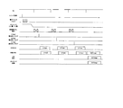
本実施形態のデジタルカメラにおける第1の撮影モードとして、静止画撮影モードについて図5のタイミングチャートを用いて説明する。VDは垂直同期信号、レリーズ信号はユーザーが操作部22に配置されたレリーズ釦を押下することにより発生する信号、メカシャッタ13は開閉により露光を制御し、電子シャッタはCCD駆動装置14で生成されたパルスをCCD12の基板電位に加え、画素1の電荷を基板方向に抜き取ることで露光を制御する。高速掃き出し(掃き捨て)動作は、垂直転送部(VCCD)2を高速で動作させ、垂直転送部2に溜まったスミアなどの信号を転送路外に掃き出す動作である。また、読み出しパルスはCCD駆動装置14にて生成され、それぞれ対応するフィールドの画素1に蓄積された信号を垂直転送部2へ読み出すために印加されるパルスである。
As a first shooting mode in the digital camera of this embodiment, a still image shooting mode will be described with reference to the timing chart of FIG. VD is a vertical synchronization signal, a release signal is a signal generated when the user presses a release button disposed on the
本実施形態のデジタルカメラにおいて静止画を撮影する際は、レリーズ後、所定の露光時間を経てメカシャッタ13が閉じられ、各画素1にその被写体の光量に応じた量の電荷が蓄積される。その後、画素の電荷を3フィールドに分割して垂直転送部2に読み出し、垂直転送部2及び水平転送部3を経由して転送する。また、各フィールドの画素を読み出す前に高速掃き出し期間を設け、垂直転送部2に残留するスミア成分等の除去を行う。この高速掃き出し期間が存在する点も、高速掃き出しを行わずに連続的に読み出す動画撮影に対し、本実施形態の静止画撮影の特徴である。図5は上記を図示したもので、レリーズ信号の後、電子シャッタパルスを印加して画素1の電荷を抜き取り、所定の露光時間を経てメカシャッタ13を閉じた後、垂直同期信号VDの周期で読み出しパルス印加とともにCCDからA、B、Cフィールドの画素を順次読み出している。各読み出しの前には上記高速掃き出し期間が設けられている。各フィールドの画素(各2,400×600)は読み出された後、プリプロセス回路15、デジタルプロセス回路16を経てメモリ17に蓄積され、さらにメモリ17上の3フィールドの画像は画像処理を経て静止画像(2,400×1,800)として生成される。これはメモリカード20に記録され、またLCD18に表示される。
When taking a still image with the digital camera of this embodiment, after the release, the
続いて、本実施形態のデジタルカメラにおける第2の撮影モードとして、動画撮影モードについて、図6のタイミングチャートを用いて説明する。 Next, a moving image shooting mode as a second shooting mode in the digital camera of the present embodiment will be described with reference to the timing chart of FIG.
本実施形態のデジタルカメラにおける動画像は、フレームレート、ファイルサイズ等を鑑みて画像サイズは静止画像の1/3程度の垂直本数でよいと考え、全画素のうちAフィールドの画素のみを読み出して、動画像とすることとしている。このとき、垂直と同様の間引き率で水平方向の画素も間引くので、最終的な動画像の画素数は、静止画2,400×1,800に対して、800×600となる。 Considering the frame rate, file size, etc., the moving image in the digital camera of this embodiment is considered to be a vertical number that is about 1/3 of the still image, and only the pixels in the A field are read out of all the pixels. , And moving images. At this time, since pixels in the horizontal direction are also thinned at the same thinning rate as vertical, the final number of pixels of the moving image is 800 × 600 with respect to the still image 2,400 × 1,800.
本実施形態における動画像の撮影は、図6に示すとおりであり、垂直同期信号VDの周期で読み出しパルス印加とともにCCDからAフィールドの画素が読み出され、プリプロセス回路15、デジタルプロセス回路16、メモリ17における画像処理を経て生成された動画像がメモリカード20に記録、あるいはLCD18に表示される。
Moving image shooting in the present embodiment is as shown in FIG. 6, and pixels in the A field are read out from the CCD along with the application of the readout pulse in the period of the vertical synchronization signal VD. A moving image generated through image processing in the
各フィールド画像の露光時間の調節は電子シャッタパルスの印加数の調節によって行われる。メカシャッタ閉及び高速掃き出し動作は行われない。 The exposure time of each field image is adjusted by adjusting the number of applied electronic shutter pulses. The mechanical shutter closing and high-speed sweeping operations are not performed.
また、各垂直同期信号VD期間にて読み出されるAフィールドの信号は2,400×600のサイズであるが、画像処理の最中に水平方向の画素が1/3に間引かれ、800×600のサイズに変更される。そして、図6に示すとおり、動画像としてメモリカード20に記録、あるいはLCD18に表示される。図7(a)は、網掛けの画素がCCDから読み出される画素(Aフィールドの画素)のうち動画像として使用される画素をあらわし、斜線の画素が水平方向に間引かれる画素をあらわしている。図7(b)は、間引き後の画素800×600をあらわしている。
The A field signal read in each vertical synchronization signal VD period has a size of 2,400 × 600, but the pixels in the horizontal direction are thinned out to 1/3 during image processing, and 800 × 600. The size is changed. Then, as shown in FIG. 6, it is recorded on the
続いて、本実施形態のデジタルカメラにおける第3の撮影モードとして、動画中静止画撮影モードについて説明する。 Subsequently, a moving image still image shooting mode will be described as a third shooting mode in the digital camera of the present embodiment.
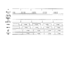
はじめに、本発明の第1の実施形態に関わる動画中静止画撮影モードについて、図8を用いて説明する。 First, the moving image still image shooting mode according to the first embodiment of the present invention will be described with reference to FIG.
動画中静止画撮影モードでは、ユーザーが操作部22に配置されたレリーズ釦を押下することによりレリーズ信号が発生され、その信号にともない静止画撮影を開始するものとする。レリーズ信号発生前の動画像撮影については、上記の第2の撮影モードである動画像撮影モードと同等であるので、説明は省略する。
In the moving image still image shooting mode, a release signal is generated when the user presses a release button disposed on the
レリーズ信号発生後について説明する。レリーズ信号が発生されると、次の垂直同期信号VDより、読み出しパルスをA、B、Cフィールドに対して各々印加して、それぞれのフィールド画像を順次読み出す。この際、各フィールド画像の露光時間の調節は電子シャッタパルスの印加数の調節によって行われる。メカシャッタ閉及び高速掃き出し動作は行われない。 A description will be given after the release signal is generated. When a release signal is generated, a read pulse is applied to each of the A, B, and C fields from the next vertical synchronizing signal VD to sequentially read out the respective field images. At this time, the exposure time of each field image is adjusted by adjusting the number of applied electronic shutter pulses. The mechanical shutter closing and high-speed sweeping operations are not performed.
また、各垂直同期信号VD期間にて読み出されるフィールドの信号は2,400×600のサイズであり、これらは読み出された後、プリプロセス回路15、デジタルプロセス回路16を経てメモリ17に蓄積される。
The field signals read out in each vertical synchronization signal VD period have a size of 2,400 × 600, and after these are read out, they are stored in the
各垂直同期信号VD期間では動画像の出力を継続する為、以下のような処理が行われる。Aフィールドの画像を読み出した場合、メモリ17上の2,400×600の画像信号に対して水平方向の画素を1/3に間引き、800×600にサイズ変更する。そして、図8に示すように動画像としてメモリカード20に記録、あるいはLCD18に表示される。図9(a)にAフィールドの重心を*で表す。
In order to continue outputting the moving image during each vertical synchronization signal VD period, the following processing is performed. When the image of the A field is read, the horizontal pixels are thinned out to 1/3 with respect to the 2,400 × 600 image signal on the
Bフィールドの画像を読み出した場合、メモリ17上の2,400×600の画像信号に対して水平方向の画素を1/3に間引き、800×600にサイズ変更する。また、他の動画像信号(Aフィールド)に対し、重心が異なる為、重心補正を施す。図9(b)にBフィールドの重心を*で表す。重心補正はAフィールドの重心にあわせるよう、☆の位置に補正する。そして、重心補正を施した画像(図中※印で示す)を図8に示すように動画像としてメモリカード20に記録、あるいはLCD18に表示される。
When the image of the B field is read out, the pixels in the horizontal direction are thinned out to 1/3 with respect to the 2,400 × 600 image signal on the
Cフィールドの画像を読み出した場合、メモリ17上の2,400×600の画像信号に対して水平方向の画素を1/3に間引き、800×600にサイズ変更する。また、他の動画像信号(Aフィールド)に対し、重心が異なる為、重心補正を施す。図9(c)にCフィールドの重心を*で表す。重心補正はAフィールドの重心にあわせるよう、☆の位置に補正する。そして、重心補正を施した画像(図中※印で示す)を図8に示すように動画像としてメモリカード20に記録、あるいはLCD18に表示される。
When the image of the C field is read, the horizontal pixels are thinned out to 1/3 with respect to the 2,400 × 600 image signal on the
以上のように、動画中静止画モードでは、重心補正を施した各フィールド画像を記録/表示に用いることで、レリーズ後も動画像を途切れさせずにすむ。 As described above, in the moving image still image mode, each field image subjected to the gravity center correction is used for recording / displaying, so that the moving image is not interrupted even after the release.
続いて、静止画像の生成について説明する。メモリ17上に記録されたA,B,Cの各フィールド画像はデジタルプロセス回路16による画像処理を経て静止画像(2,400×1,800)として生成される。これは動画像記録/表示の終了後、メモリカード20に記録される。
Subsequently, generation of a still image will be described. Each field image of A, B, and C recorded on the
以上のように、本実施形態により動画像撮影中の任意の時点で、表示・記録中の動画像を途切れさせることなく、高精細な静止画像を撮影することができることとなる。 As described above, according to the present embodiment, a high-definition still image can be taken at any time during moving image shooting without interrupting the moving image being displayed / recorded.
(第2の実施形態)
本発明の第2の実施形態に関わる動画中静止画撮影モードについて、図10を用いて説明する。
(Second Embodiment)
A moving image still image shooting mode according to the second embodiment of the present invention will be described with reference to FIG.
動画中静止画撮影モードでは、ユーザーが操作部22に配置されたレリーズ釦を押下することによりレリーズ信号が発生され、その信号にともない静止画撮影を開始するものとする。レリーズ信号発生前の動画像撮影については、上記の第2の撮影モードである動画像撮影モードと同等であるので、説明は省略する。
In the moving image still image shooting mode, a release signal is generated when the user presses a release button disposed on the
レリーズ信号発生後について説明する。レリーズ信号が発生されると、所定の露光時間を経てメカシャッタ13が閉じられる。そして次の垂直同期信号VDより、読み出しパルスをA、B、Cフィールドに対して各々印加して、それぞれのフィールド画像を順次読み出す。この際、メカシャッタ閉までの露光時間の調節は電子シャッタパルスの印加数の調節によって行われる。また各読み出しの前には高速掃き出し期間が設けられ、垂直転送部に残留するスミア成分等の除去を行っている。
A description will be given after the release signal is generated. When the release signal is generated, the
また、各垂直同期信号VD期間にて読み出されるフィールドの信号は2,400×600のサイズであり、これらは読み出された後、プリプロセス回路15、デジタルプロセス回路16を経てメモリ17に蓄積される。
The field signals read out in each vertical synchronization signal VD period have a size of 2,400 × 600, and after these are read out, they are stored in the
各垂直同期信号VD期間では動画像の出力を継続する為、以下のような処理が行われる。Aフィールドの画像を読み出した場合、メモリ17上の2,400×600の画像信号に対して水平方向の画素を1/3に間引き、800×600にサイズ変更する。そして、図10に示すように動画像としてメモリカード20に記録、あるいはLCD18に表示される。
In order to continue outputting the moving image during each vertical synchronization signal VD period, the following processing is performed. When the image of the A field is read, the horizontal pixels are thinned out to 1/3 with respect to the 2,400 × 600 image signal on the
Bフィールドの画像を読み出した場合、メモリ17上の2,400×600の画像信号に対して水平方向の画素を1/3に間引き、800×600にサイズ変更する。また、他の動画像信号(Aフィールド)に対し、重心が異なる為、重心補正を施す。図9(b)にBフィールドの重心を*で表す。重心補正はAフィールドの重心にあわせるよう、☆の位置に補正する。そして、重心補正を施した画像(図中※印で示す)を図10に示すように動画像としてメモリカード20に記録、あるいはLCD18に表示される。
When the image of the B field is read out, the pixels in the horizontal direction are thinned out to 1/3 with respect to the 2,400 × 600 image signal on the
Cフィールドの画像を読み出した場合、メモリ17上の2,400×600の画像信号に対して水平方向の画素を1/3に間引き、800×600にサイズ変更する。また、他の動画像信号(Aフィールド)に対し、重心が異なる為、重心補正を施す。図9(c)にCフィールドの重心を*で表す。重心補正はAフィールドの重心にあわせるよう、☆の位置に補正する。そして、重心補正を施した画像(図中※印で示す)を図10に示すように動画像としてメモリカード20に記録、あるいはLCD18に表示される。
When the image of the C field is read, the horizontal pixels are thinned out to 1/3 with respect to the 2,400 × 600 image signal on the
以上のように、動画中静止画撮影モードでは、重心補正を施した各フィールド画像を記録/表示に用いることで、レリーズ後も動画像を途切れさせずにすむ。 As described above, in the moving image still image shooting mode, each field image subjected to gravity center correction is used for recording / displaying, so that the moving image is not interrupted even after the release.
続いて、静止画像の生成について説明する。メモリ17上に記録されたA,B,Cの各フィールド画像はデジタルプロセス回路16による画像処理を経て静止画像(2,400×1,800)として生成される。これは動画像記録/表示の終了後、メモリカード20に記録される。
Subsequently, generation of a still image will be described. Each field image of A, B, and C recorded on the
以上のように、本実施形態により動画像撮影中の任意の時点で、表示・記録中の動画像を途切れさせることなく、高精細な静止画像を撮影することができることとなる。さらに、全フィールドを順次読み出す際にメカニカルシャッタを閉じることにより、フィールド間の露光時刻ずれがなくなり、静止画像において動く被写体の偽色を抑えることができることとなる。 As described above, according to the present embodiment, a high-definition still image can be taken at any time during moving image shooting without interrupting the moving image being displayed / recorded. Further, by closing the mechanical shutter when sequentially reading all fields, there is no exposure time shift between fields, and the false color of a moving subject in a still image can be suppressed.
以上のように、第1及び第2の実施形態によれば、レリーズ釦により静止画撮影が指示されたときには、動画中静止画撮影モードになる。動画中静止画撮影モードでは、CCD12の全画素をインターレース走査で3フィールドに分けて順次画像信号を読み出す例を説明したが、3フィールドに限定されず、mフィールド(mは2以上の自然数)に分けて読み出すことができる。そして、その読み出したmフィールドの画像信号を基にmフィールドの動画像信号を生成すると共に1フレームの静止画像信号を生成する。これにより、動画像撮影中の任意の時点で、表示・記録中の動画像を途切れさせることなく、高精細な静止画像を撮影することができる。
As described above, according to the first and second embodiments, when still image shooting is instructed by the release button, the moving image still image shooting mode is set. In the moving image still image shooting mode, the example in which all the pixels of the
また、レリーズ釦により静止画撮影が指示されないときは動画撮影モードになる。動画撮影モードでは、mフィールドのうちの特定の1フィールド(例えばAフィールド)の画像信号を垂直同期信号VDに同期して連続して読み出し、その連続して読み出した特定の1フィールドの画像信号を基に動画像信号を生成する。 In addition, when a still image shooting is not instructed by the release button, the moving image shooting mode is set. In the moving image shooting mode, an image signal of a specific one field (for example, A field) of m fields is continuously read in synchronization with the vertical synchronization signal VD, and the image signal of the specific one field read continuously is read. Based on this, a moving image signal is generated.
上記実施形態は、何れも本発明を実施するにあたっての具体化の例を示したものに過ぎず、これらによって本発明の技術的範囲が限定的に解釈されてはならないものである。すなわち、本発明はその技術思想、またはその主要な特徴から逸脱することなく、様々な形で実施することができる。 The above-described embodiments are merely examples of implementation in carrying out the present invention, and the technical scope of the present invention should not be construed as being limited thereto. That is, the present invention can be implemented in various forms without departing from the technical idea or the main features thereof.
1 光電変換素子(画素)
2 垂直転送部(VCCD)
3 水平転送部(HCCD)
4 出力アンプ部
11 レンズなどからなる光学系
12 CCD
13 メカシャッタ
14 CCD駆動装置
15 プリプロセス回路
16 デジタルプロセス回路
17 メモリ
18 ディスプレイ(LCD)
19 画像変換回路
20 メモリカード
21 カメラ制御部
22 操作部
1 Photoelectric conversion element (pixel)
2 Vertical transfer unit (VCCD)
3 Horizontal transfer unit (HCCD)
4
13 Mechanical shutter 14
19
Claims (7)
前記撮像素子の複数の画素からmフィールド(mは2以上の自然数)に分けて順次画像信号を読み出す第1の読み出し手段と、
前記mフィールドのうちの特定の1フィールドの画像信号を連続して読み出す第2の読み出し手段と、
前記読み出したmフィールドの画像信号を基にmフィールドの動画像信号を生成すると共に1フレームの静止画像信号を生成する第1の画像生成手段と、
前記連続して読み出した特定の1フィールドの画像信号を基に動画像信号を生成する第2の画像生成手段と
を有することを特徴とする撮像装置。 An image sensor for generating an image signal by photoelectric conversion for each pixel;
First reading means for sequentially reading image signals from a plurality of pixels of the image sensor in m fields (m is a natural number of 2 or more);
Second reading means for continuously reading image signals of one specific field of the m fields;
First image generating means for generating an m-field moving image signal based on the read m-field image signal and generating a still image signal of one frame;
An image pickup apparatus comprising: a second image generation unit configured to generate a moving image signal based on the image signal of the specific one field read out continuously.
前記第1の読み出し手段は、前記mフィールドの画像信号を順次読み出す際に、前記メカニカルシャッタを閉じることにより光を遮断することを特徴とする請求項1〜4のいずれか1項に記載の撮像装置。 Furthermore, it has a mechanical shutter for blocking light incident on the image sensor,
5. The imaging according to claim 1, wherein the first reading unit blocks light by closing the mechanical shutter when sequentially reading the image signals of the m field. apparatus.
前記第1の読み出し手段は、3フィールドに分けて順次画像信号を読み出し、
前記第2の読み出し手段は、前記3フィールドのうちの特定の1フィールドの画像信号を連続して読み出すことを特徴とする請求項1〜5のいずれか1項に記載の撮像装置。 The imaging element includes a line in which the first color and the second color are alternately arranged in the order of the first color and the second color, and the third color and the first color are the third color. The colors and the lines alternately arranged in the order of the first color are arranged alternately,
The first readout means sequentially reads out image signals in three fields,
6. The imaging apparatus according to claim 1, wherein the second reading unit continuously reads an image signal of one specific field among the three fields. 7.
前記撮像素子の複数の画素からmフィールド(mは2以上の自然数)に分けて順次画像信号を読み出す第1の読み出しステップと、
前記mフィールドのうちの特定の1フィールドの画像信号を連続して読み出す第2の読み出しステップと、前記読み出したmフィールドの画像信号を基にmフィールドの動画像信号を生成すると共に1フレームの静止画像信号を生成する第1の画像生成ステップと、
前記連続して読み出した特定の1フィールドの画像信号を基に動画像信号を生成する第2の画像生成ステップと
を有することを特徴とする撮像方法。
An imaging method of an imaging apparatus having an imaging element for generating an image signal by photoelectric conversion for each pixel,
A first readout step of sequentially reading out an image signal from a plurality of pixels of the imaging device in m fields (m is a natural number of 2 or more);
A second readout step of successively reading out the image signal of one specific field of the m fields, generating a moving image signal of the m field based on the read out image signal of the m field, and stillness of one frame A first image generation step for generating an image signal;
And a second image generation step of generating a moving image signal based on the image signal of the specific one field read out continuously.
Priority Applications (1)
| Application Number | Priority Date | Filing Date | Title |
|---|---|---|---|
| JP2005051776A JP2006238205A (en) | 2005-02-25 | 2005-02-25 | Imaging apparatus and imaging method |
Applications Claiming Priority (1)
| Application Number | Priority Date | Filing Date | Title |
|---|---|---|---|
| JP2005051776A JP2006238205A (en) | 2005-02-25 | 2005-02-25 | Imaging apparatus and imaging method |
Publications (2)
| Publication Number | Publication Date |
|---|---|
| JP2006238205A true JP2006238205A (en) | 2006-09-07 |
| JP2006238205A5 JP2006238205A5 (en) | 2010-03-25 |
Family
ID=37045345
Family Applications (1)
| Application Number | Title | Priority Date | Filing Date |
|---|---|---|---|
| JP2005051776A Pending JP2006238205A (en) | 2005-02-25 | 2005-02-25 | Imaging apparatus and imaging method |
Country Status (1)
| Country | Link |
|---|---|
| JP (1) | JP2006238205A (en) |
Cited By (2)
| Publication number | Priority date | Publication date | Assignee | Title |
|---|---|---|---|---|
| JP2008078794A (en) * | 2006-09-19 | 2008-04-03 | Pentax Corp | Image sensor driver |
| EP2518996A3 (en) * | 2007-05-10 | 2013-04-03 | Isis Innovation Limited | Image capture device and method |
Citations (10)
| Publication number | Priority date | Publication date | Assignee | Title |
|---|---|---|---|---|
| JPH06189175A (en) * | 1992-12-18 | 1994-07-08 | Yoshiomi Kuriwaka | Image pickup device |
| JP2000184385A (en) * | 1998-12-17 | 2000-06-30 | Sony Corp | Solid-state image pickup element, its drive method and camera system |
| JP2001352483A (en) * | 2000-06-07 | 2001-12-21 | Matsushita Electric Ind Co Ltd | Moving image and static image image pickup device |
| JP2002044531A (en) * | 2000-07-27 | 2002-02-08 | Sony Corp | Image pickup device, image recorder, image recording/ reproducing device and image transmission method |
| JP2003052049A (en) * | 2001-08-08 | 2003-02-21 | Canon Inc | Imaging apparatus |
| JP2003219275A (en) * | 2002-01-25 | 2003-07-31 | Olympus Optical Co Ltd | Imaging apparatus |
| JP2003224858A (en) * | 2002-01-30 | 2003-08-08 | Ricoh Co Ltd | Digital camera |
| JP2004056422A (en) * | 2002-07-19 | 2004-02-19 | Fuji Photo Film Co Ltd | Solid-state image pickup device and photometry method thereof |
| JP2004343607A (en) * | 2003-05-19 | 2004-12-02 | Matsushita Electric Ind Co Ltd | Image server |
| JP2005027120A (en) * | 2003-07-03 | 2005-01-27 | Olympus Corp | Bidirectional data communication system |
-
2005
- 2005-02-25 JP JP2005051776A patent/JP2006238205A/en active Pending
Patent Citations (10)
| Publication number | Priority date | Publication date | Assignee | Title |
|---|---|---|---|---|
| JPH06189175A (en) * | 1992-12-18 | 1994-07-08 | Yoshiomi Kuriwaka | Image pickup device |
| JP2000184385A (en) * | 1998-12-17 | 2000-06-30 | Sony Corp | Solid-state image pickup element, its drive method and camera system |
| JP2001352483A (en) * | 2000-06-07 | 2001-12-21 | Matsushita Electric Ind Co Ltd | Moving image and static image image pickup device |
| JP2002044531A (en) * | 2000-07-27 | 2002-02-08 | Sony Corp | Image pickup device, image recorder, image recording/ reproducing device and image transmission method |
| JP2003052049A (en) * | 2001-08-08 | 2003-02-21 | Canon Inc | Imaging apparatus |
| JP2003219275A (en) * | 2002-01-25 | 2003-07-31 | Olympus Optical Co Ltd | Imaging apparatus |
| JP2003224858A (en) * | 2002-01-30 | 2003-08-08 | Ricoh Co Ltd | Digital camera |
| JP2004056422A (en) * | 2002-07-19 | 2004-02-19 | Fuji Photo Film Co Ltd | Solid-state image pickup device and photometry method thereof |
| JP2004343607A (en) * | 2003-05-19 | 2004-12-02 | Matsushita Electric Ind Co Ltd | Image server |
| JP2005027120A (en) * | 2003-07-03 | 2005-01-27 | Olympus Corp | Bidirectional data communication system |
Cited By (6)
| Publication number | Priority date | Publication date | Assignee | Title |
|---|---|---|---|---|
| JP2008078794A (en) * | 2006-09-19 | 2008-04-03 | Pentax Corp | Image sensor driver |
| EP2518996A3 (en) * | 2007-05-10 | 2013-04-03 | Isis Innovation Limited | Image capture device and method |
| CN103067660A (en) * | 2007-05-10 | 2013-04-24 | 爱西斯创新有限公司 | Image capture device and method |
| US8508608B2 (en) | 2007-05-10 | 2013-08-13 | Isis Innovation Ltd. | Image capture device and method of capturing images |
| US8570388B2 (en) | 2007-05-10 | 2013-10-29 | Isis Innovation Ltd. | Image capture device and method |
| EP2145467B1 (en) * | 2007-05-10 | 2014-05-07 | ISIS Innovation Limited | Image capture device and method |
Similar Documents
| Publication | Publication Date | Title |
|---|---|---|
| US6903770B1 (en) | Digital camera which produces a single image based on two exposures | |
| JP4951440B2 (en) | Imaging apparatus and solid-state imaging device driving method | |
| JPH10210367A (en) | Electronic image-pickup device | |
| US7760257B2 (en) | Image capturing apparatus, control method and program thereof, and storage medium | |
| JP2005057378A (en) | Imaging apparatus | |
| JP2009017459A (en) | Ccd solid-state imaging element, driving method thereof, and imaging apparatus | |
| JP4678849B2 (en) | IMAGING DEVICE, ITS CONTROL METHOD, PROGRAM, AND STORAGE MEDIUM | |
| US7236194B2 (en) | Image signal processing apparatus | |
| JP2007325026A (en) | Image pickup device, its driving method, its signal processing method, and electronic information equipment | |
| JP2006228801A (en) | Solid state imaging element | |
| JP2006238205A (en) | Imaging apparatus and imaging method | |
| US7616354B2 (en) | Image capture apparatus configured to divisionally read out accumulated charges with a plurality of fields using interlaced scanning | |
| JP2001352483A (en) | Moving image and static image image pickup device | |
| JP3738654B2 (en) | Digital camera | |
| JP5106056B2 (en) | Imaging apparatus and flicker detection method thereof | |
| JP4022682B2 (en) | Imaging apparatus and image output method | |
| JP2005303653A (en) | Image pickup device | |
| JP4112106B2 (en) | Imaging device | |
| JP4302485B2 (en) | Imaging device, image acquisition device, and imaging system | |
| JP4527027B2 (en) | Imaging apparatus and imaging method | |
| JP2006074440A (en) | Imaging apparatus | |
| JP3846707B2 (en) | Method for driving solid-state imaging device and camera | |
| JP2004120391A (en) | Solid-state image pickup device | |
| JP2004096546A (en) | Solid-state image pickup device | |
| JP2000013686A (en) | Image pickup device |
Legal Events
| Date | Code | Title | Description |
|---|---|---|---|
| A621 | Written request for application examination |
Free format text: JAPANESE INTERMEDIATE CODE: A621 Effective date: 20080225 |
|
| A521 | Request for written amendment filed |
Free format text: JAPANESE INTERMEDIATE CODE: A523 Effective date: 20100204 |
|
| A977 | Report on retrieval |
Free format text: JAPANESE INTERMEDIATE CODE: A971007 Effective date: 20100210 |
|
| A131 | Notification of reasons for refusal |
Free format text: JAPANESE INTERMEDIATE CODE: A131 Effective date: 20100223 |
|
| A521 | Request for written amendment filed |
Free format text: JAPANESE INTERMEDIATE CODE: A523 Effective date: 20100422 |
|
| A131 | Notification of reasons for refusal |
Free format text: JAPANESE INTERMEDIATE CODE: A131 Effective date: 20110208 |
|
| A521 | Request for written amendment filed |
Free format text: JAPANESE INTERMEDIATE CODE: A523 Effective date: 20110408 |
|
| A131 | Notification of reasons for refusal |
Free format text: JAPANESE INTERMEDIATE CODE: A131 Effective date: 20111213 |
|
| A521 | Request for written amendment filed |
Free format text: JAPANESE INTERMEDIATE CODE: A523 Effective date: 20120208 |
|
| A02 | Decision of refusal |
Free format text: JAPANESE INTERMEDIATE CODE: A02 Effective date: 20120703 |