JP2006238112A - Notification apparatus, notification condition designating apparatus and state notification method - Google Patents
Notification apparatus, notification condition designating apparatus and state notification method Download PDFInfo
- Publication number
- JP2006238112A JP2006238112A JP2005050440A JP2005050440A JP2006238112A JP 2006238112 A JP2006238112 A JP 2006238112A JP 2005050440 A JP2005050440 A JP 2005050440A JP 2005050440 A JP2005050440 A JP 2005050440A JP 2006238112 A JP2006238112 A JP 2006238112A
- Authority
- JP
- Japan
- Prior art keywords
- notification
- state
- condition
- notification condition
- information
- Prior art date
- Legal status (The legal status is an assumption and is not a legal conclusion. Google has not performed a legal analysis and makes no representation as to the accuracy of the status listed.)
- Withdrawn
Links
Images


Landscapes
- Telephonic Communication Services (AREA)
- Mobile Radio Communication Systems (AREA)
Abstract
Description
本発明は、機器もしくは機器のユーザの状態を通知する通知装置、通知条件指定装置および状態通知方法に関する。 The present invention relates to a notification device, a notification condition designation device, and a state notification method for notifying a device or a user status of the device.
近年、通信相手の接続状態(オンライン/オフライン)を知ることができるプレゼンスサービスが簡易テキストメール交換サービス(IM:Instant Message)などで使われてきている。また、企業におけるプレゼンスサービスとしては、通信相手の在席状態(在席/不在)をネットワーク経由で通知するサービスが普及しつつある。 In recent years, a presence service that can know a connection state (online / offline) of a communication partner has been used in a simple text mail exchange service (IM: Instant Message) or the like. In addition, as a presence service in a company, a service for notifying the presence / absence of a communication partner via a network is becoming widespread.
このようなサービスを提供するための一つの方法として、IETF(Internet Engineering Task Force)のRFC3261(発行:2002.6)及びRFC3265(発行:2002.6)に示されるSIP(Session Initiation Protocol)のイベント通知機能がある。SIPイベント通知機能を使って企業におけるプレゼンスサービスを実現する場合としては、例えば、社員の状態を管理するプレゼンスサーバを設置し、社員の状態が変化したら、状態通知要求をしている人に向けて状態変化通知を送信する。 As one method for providing such a service, SIP (Session Initiation Protocol) events indicated in RFC 3261 (issue: 20022.6) and RFC 3265 (issue: 20022.6) of IETF (Internet Engineering Task Force) There is a notification function. When implementing a presence service in a company using the SIP event notification function, for example, a presence server for managing the status of an employee is installed. Send a state change notification.
図22は、従来の通知装置と通知条件指定装置兼被通知装置の例であるSIPイベント通知機能を使ったプレゼンスサービスにおけるネットワーク構成を示す図である。コンピュータ(PCとも記す)701〜704は、社内LAN710に接続されており、PCを使用するユーザのプレゼンス状態(在席/不在)の状態を持つ。通知装置であるプレゼンスサーバ700は、PC701〜704の状態を管理し、状態通知の要求があり、状態に変化があった場合は状態通知要求をしている機器、すなわち被通知装置に向けて状態変化を通知する。
FIG. 22 is a diagram showing a network configuration in a presence service using a SIP event notification function, which is an example of a conventional notification device, notification condition designating device and notified device. Computers (also referred to as PCs) 701 to 704 are connected to the in-
例えば、PC701の状態が「在席」であり、通知条件指定装置でもあり、被通知装置であるPC704が、PC701の状態通知をPC704に行なうように要求したら、プレゼンスサーバ700は、PC701が「在席」であることをPC704に通知する。次に、PC701が「在席」から「不在」に変化した場合は、プレゼンスサーバ700に「不在」という状態を登録する。プレゼンスサーバはPC701の状態を「在席」から「不在」に更新し、PC701の状態通知要求をしているPC704に対して状態変化を通知する。
For example, if the PC 701 is “attended” and is also a notification condition designation device, and the PC 704 as a notified device requests the PC 704 to notify the PC 704 of the status, the
このような状態通知に使われるSIPのメッセージについて図23を用いて説明する。図23は、従来の通知装置及び被通知装置におけるSIPを使ったプレゼンスサービスのメッセージフローを示す図である。PC701は自装置の状態を記述した発行メッセージ(以下、PUBLISHとも記す)をプレゼンスサーバ700に送信し、現在の状態をプレゼンスサーバ700に登録する。プレゼンスサーバ700はPUBLISHを受信してPC701の状態を登録すると、SIPで規定された「200 OK応答」を返す。
A SIP message used for such status notification will be described with reference to FIG. FIG. 23 is a diagram illustrating a message flow of a presence service using SIP in a conventional notification device and a notified device. The PC 701 transmits an issuance message (hereinafter also referred to as “PUBLISH”) describing the state of the own device to the
通知条件指定装置でもあり、被通知装置であるPC704はPC701の状態通知を要求するために、PC701のURI(Uniform Resource Identifier)と通知を要求する状態の種類(ここではプレゼンス)を記述した状態講読メッセージ(以下、SUBSCRIBEとも記す)をプレゼンスサーバ700に送信する。プレゼンスサーバ700はSUBSCRIBEを受信し通知要求を受け入れると、「200 OK応答」を返す。その後、プレゼンスサーバ700はPC701の状態を記述した通知メッセージ(以下、NOTIFYとも記す)をPC704に送信する。
In order to request the PC 701 status notification, the PC 704, which is also a notification condition specifying device and a notified device, requests a status notification describing the URI (Uniform Resource Identifier) of the PC 701 and the type of status requesting the notification (here, presence). A message (hereinafter also referred to as SUBSCRIBE) is transmitted to the
PC704はNOTIFYを受信し、PC701の状態を取得するとプレゼンスサーバ700に対して「200 OK応答」を返す。その後、PC701は自装置の状態が変化するたびにプレゼンスサーバ700にPUBLISHを送信する。プレゼンスサーバ700はPC701からのPUBLISHを受信すると、PC701の状態を記述したNOTIFYをPC704に送信する。
When the PC 704 receives NOTIFY and acquires the state of the PC 701, it returns a “200 OK response” to the
以上のようにSIPイベント通知機能を使うことによって、プレゼンスサービスを代表とする状態通知サービスを実現できる。現在、通知できる状態は社員の居場所や行動状態などに限られているが、今後はそれだけに限らずネットワークに接続された全ての機器の状態を通知するサービスの出現が予想される。ところが通知する状態や機器が増えることで状態を管理するサーバでの処理負荷増大が問題となり、負荷軽減を図る必要がでてくる。 By using the SIP event notification function as described above, a status notification service represented by a presence service can be realized. Currently, the status that can be notified is limited to the whereabouts and the behavioral status of the employee, but in the future, not only that but services that notify the status of all devices connected to the network are expected to appear. However, as the number of notification states and devices increases, an increase in processing load on the server managing the state becomes a problem, and it is necessary to reduce the load.
この負荷軽減方法としては、例えばIETFのSIMPLE(SIP for Instant Messaging and Presence Leveraging Extensions)ワーキンググループで提案されているイベントフィルタがある。イベントフィルタについて図24を用いて説明する。図24は、従来の通知装置及び通知条件指定装置におけるイベントフィルタのメッセージフローを示す図である。 As this load reduction method, for example, there is an event filter proposed in the IETF SIMPLE (SIP for Instant Messaging and Presence Leveraging Extensions) working group. The event filter will be described with reference to FIG. FIG. 24 is a diagram illustrating a message flow of an event filter in a conventional notification device and notification condition designating device.
イベントフィルタによれば、通知装置において、ある機器が指定された状態になったときだけNOTIFYを送信することが可能となる。PC704はSUBSCRIBEを送信する際に、NOTIFYを生成する条件をSUBSCRIBEのボディ部に記述する。この例では「PC701が不在になったときだけ通知」という条件を記述しておく。なお、実際の条件の記述はXML(Extensible Markup Language)が使われるが、ここでは詳細な説明を省略する。プレゼンスサーバ700はSUBSCRIBEを受信すると、PC701の状態を記述したNOTIFYをPC704に送信する。SUBSCRIBE受信後、最初に送信されるNOTIFYについては、SUBSCRIBEに記述された条件を満たさない場合でも送信される。
According to the event filter, it is possible to transmit NOTIFY only when a certain device is in a designated state in the notification device. When transmitting the SUBSCRIBE, the PC 704 describes a condition for generating NOTIFY in the body part of the SUBSCRIBE. In this example, a condition “notify only when the PC 701 is absent” is described. In addition, although XML (Extensible Markup Language) is used for description of actual conditions, detailed description is abbreviate | omitted here. When the
その後、従来の通知装置であるプレゼンスサーバ700は、「在席」という状態を登録するPUBLISHを受信した場合はNOTIFYを送信せず、「不在」という状態を登録するPUBLISHを受信した場合にのみ、従来の被通知装置であるPC704にNOTIFYを送信する。
After that, the
このようにイベントフィルタはPC704が指定した条件を満たすときだけNOTIFYを送信するので不要なNOTIFYトラヒックが減り、ネットワークリソースを有効に利用できるとともにプレゼンスサーバ700のNOTIFY送信処理負荷を軽減することができる(例えば、非特許文献1参照)。
しかしながら、前記従来の通知装置及び通知条件指定装置では、指定可能な条件が単一の機器の状態のみであり、複数の機器の状態を指定することについては開示されていなかった。このため、例えば「ユーザAもしくはユーザBが在席であり、ユーザCが在席でない」状態となった場合にだけ通知、というような指定ができず、不要なNOTIFYが送信されるという問題があった。 However, in the conventional notification device and notification condition designating device, the condition that can be designated is only the state of a single device, and it is not disclosed that the states of a plurality of devices are designated. For this reason, for example, it is not possible to specify such as notification only when “user A or user B is present and user C is not present”, and an unnecessary NOTIFY is transmitted. there were.
本発明は、従来の問題を解決するためになされたもので、複数の機器若しくは機器のユーザの状態により通知条件を指定でき、不要な通知情報を減らすことを可能とする通知装置、被通知装置および状態通知方法を提供することを目的とする。 The present invention has been made in order to solve the conventional problems, and can provide notification devices that can specify notification conditions according to the states of a plurality of devices or users of devices, and can reduce unnecessary notification information, and notified devices It is another object of the present invention to provide a status notification method.
本発明の通知装置は、被通知装置に通知する条件である通知条件を記憶する通知条件記憶手段と、個々の機器あるいは機器のユーザである状態情報提供者が提供する状態情報を取得する状態情報取得手段と、状態情報取得手段で取得した複数の状態情報が通知条件を満たす場合に通知情報を被通知装置に送信する送信手段と、を含む通知装置であって、通知条件が、複数の状態条件からなる論理条件で示され、複数の状態条件を構成する個々の状態条件が、個々の状態条件に対応する状態情報発行者の状態項目と状態値との組を含む構成を有している。 The notification device according to the present invention includes a notification condition storage unit that stores a notification condition that is a condition for notification to a notified device, and status information that acquires status information provided by an individual device or a status information provider that is a user of the device. A notification device including an acquisition unit and a transmission unit configured to transmit notification information to a notification target device when a plurality of state information acquired by the state information acquisition unit satisfies a notification condition. Each state condition that is indicated by a logical condition consisting of a condition and that constitutes a plurality of state conditions has a configuration that includes a set of a state item and a state value of a state information issuer corresponding to each state condition .
この構成により、複数の機器若しくは機器のユーザの状態による論理条件により通知条件を指定でき、不要な通知情報を減らすことが可能となる。 With this configuration, notification conditions can be specified by logical conditions depending on the states of a plurality of devices or user of devices, and unnecessary notification information can be reduced.
また本発明の通知装置は、送信手段が、状態情報取得手段で取得した複数の状態情報からなる論理条件が通知条件を満たさない場合には通知情報を被通知装置に送信しない構成を有している。この構成により、これによって不要な通知情報の送信が抑えられ、通信リソースを有効に使えるとともに、送信手段の送信処理負荷を軽減できる。 In addition, the notification device of the present invention has a configuration in which the transmission unit does not transmit the notification information to the notified device when the logical condition including the plurality of state information acquired by the state information acquisition unit does not satisfy the notification condition. Yes. With this configuration, unnecessary transmission of notification information can be suppressed, communication resources can be used effectively, and the transmission processing load on the transmission means can be reduced.
また、本発明の通知装置は、状態情報発行者の少なくとも1つが通知装置である構成を有している。この構成により、通知装置自身の状態を通知条件として指定することが可能となり、より複雑な通知条件の指定が可能となる。 In addition, the notification device of the present invention has a configuration in which at least one of the status information issuers is a notification device. With this configuration, the state of the notification device itself can be specified as a notification condition, and more complicated notification conditions can be specified.
また、本発明の通知装置は、通知条件を受信する通知条件受信手段を更に含み、通知条件受信手段で受信した通知条件を通知条件記憶手段に記憶する構成を有している。この構成により、他の装置が通知条件を指定することが可能となる。例えば通知情報を受信する被通知装置が通知条件を指定することにより、被通知装置が所望のタイミングで通知を受けることができる。さらに被通知装置が必要としないタイミングでの通知が無くなるため、ネットワークリソースを有効に使えるとともに、通知パケットの送受信処理負荷が軽減される。 The notification device of the present invention further includes notification condition receiving means for receiving notification conditions, and has a configuration for storing the notification conditions received by the notification condition receiving means in the notification condition storage means. With this configuration, it becomes possible for another device to specify a notification condition. For example, the notified device that receives the notification information specifies the notification condition, so that the notified device can receive the notification at a desired timing. Further, since notification at a timing not required by the notified device is eliminated, network resources can be used effectively, and the transmission / reception processing load of the notification packet is reduced.
また、本発明の通知装置は、論理条件が、AND(かつ)と、OR(または)と、NOT(否定)の少なくとも一つを含む構成を有している。複数の状態条件を簡単なAND/OR/NOTで結ぶような条件指定が可能となる。例えば「(ユーザAが会議室に居る OR ユーザBが会議室にいる) AND ユーザCは会議室に居ない」といった通知条件の指定が可能となり、より適切なタイミングで通知することが可能となる。 The notification device of the present invention has a configuration in which the logical condition includes at least one of AND (and), OR (or), and NOT (negative). It is possible to specify conditions that connect a plurality of state conditions with simple AND / OR / NOT. For example, it is possible to specify a notification condition such as “(User A is in the conference room OR User B is in the conference room) AND User C is not in the conference room”, and notification can be made at a more appropriate timing. .
また、本発明の通知装置は、送信手段が、通知情報の送信にSIP(Session Initiation Protocol)を使用する構成を有している。SIPのイベント通知機能を使用した場合でも通知条件の指定が可能となり、通信リソースを有効に使えるとともに、通知情報の送信処理負荷が軽減される。 Moreover, the notification device of the present invention has a configuration in which the transmission means uses SIP (Session Initiation Protocol) for transmission of the notification information. Even when the SIP event notification function is used, a notification condition can be specified, communication resources can be used effectively, and the transmission processing load of notification information is reduced.
さらに、本発明の通知条件指定装置は、通知装置が通知情報を被通知装置に送信する条件である通知条件を取得する通知条件取得手段と、通知条件取得手段で取得した通知条件を通知装置に送信する通知条件送信手段と、を含む通知条件指定装置であって、通知条件は、複数の状態条件からなる論理条件で示され、複数の状態条件を構成する個々の状態条件は、個々の状態条件に対応する状態情報発行者の状態項目と状態値との組を含み、状態情報発行者は、個々の機器あるいは機器のユーザである構成を有している。 Furthermore, the notification condition designating device of the present invention provides a notification condition acquisition unit that acquires a notification condition, which is a condition for the notification device to transmit notification information to the notified device, and the notification condition acquired by the notification condition acquisition unit. A notification condition specifying device including a notification condition transmitting means, wherein the notification condition is indicated by a logical condition composed of a plurality of state conditions, and each state condition constituting the plurality of state conditions is an individual state It includes a set of status items and status values of status information issuers corresponding to the conditions, and the status information issuer has a configuration that is an individual device or a user of the device.
この構成により、通知装置に対し、任意に通知条件を指定することができる。 With this configuration, notification conditions can be arbitrarily designated for the notification device.
本発明は、被通知装置に通知する条件である通知条件を記憶する通知条件記憶手段と、個々の機器あるいは機器のユーザである状態情報提供者が提供する状態情報を取得する状態情報取得手段と、状態情報取得手段で取得した複数の状態情報が通知条件を満たす場合に通知情報を被通知装置に送信する送信手段とを含み、通知条件が、複数の状態条件からなる論理条件で示され、複数の状態条件を構成する個々の状態条件が、個々の状態条件に対応する状態情報発行者の状態項目と状態値との組を含むことにより、複数の機器若しくは機器のユーザの状態により通知条件を指定でき、不要な通知情報を減らすことが可能となるという効果を有する通知装置を提供することができる。 The present invention relates to a notification condition storage unit that stores a notification condition that is a condition to be notified to a notified device, and a state information acquisition unit that acquires state information provided by an individual device or a state information provider that is a user of the device. A plurality of state information acquired by the state information acquisition unit includes a transmission unit that transmits notification information to the notified device when the notification condition is satisfied, and the notification condition is indicated by a logical condition including a plurality of state conditions, Each state condition that constitutes a plurality of state conditions includes a set of state items and state values of the state information issuer corresponding to each state condition. Can be specified, and a notification device having an effect that unnecessary notification information can be reduced can be provided.
以下、本発明の実施の形態の通知装置および通知条件指定装置について、図面を参照しながら説明する。 Hereinafter, a notification device and a notification condition designating device according to an embodiment of the present invention will be described with reference to the drawings.
(実施の形態1)
図1は、本発明の実施の形態1における通知装置を含むネットワーク構成図である。
(Embodiment 1)
FIG. 1 is a network configuration diagram including a notification device according to
図1において、通知装置(以下、プレゼンスサーバとも記す)100は、携帯電話101、PC102、固定電話103、PC104とネットワーク110によって接続されている。携帯電話101、PC102、固定電話103はユーザ120が所有する機器であり、それぞれが持つ状態が変化するたびにプレゼンスサーバ100に状態登録を行う。PC104はユーザ130が所有する機器であり、プレゼンスサーバ100からの状態通知を受ける被通知装置である。
In FIG. 1, a notification device (hereinafter also referred to as a presence server) 100 is connected to a
プレゼンスサーバ100は各機器の状態を保持・管理し、PC104に対して状態通知を行う。実施の形態1では、プレゼンスサーバ100のキー入力部からのキー入力により、「携帯電話101が通話可能、もしくはPC102が現在ユーザに使用されており固定電話が通話可能」という通知条件を設定し、プレゼンスサーバ100は通知条件を満たすときのみ、被通知装置であるPC104に状態通知を行う例を示す。なお、本実施の形態で、通知条件の設定はキー入力部からのキー入力により行なう場合で説明するが、本発明はこれに限定することなく、タッチパネルやマウスといったポインティングデバイスや音声認識入力手段他でも実施可能である。
The
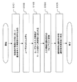
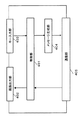
まず、図2を用いて、本発明の実施の形態1における通知装置の動作を示すメッセージフローを説明する。なお、実施の形態1ではSIP(Session Initiation Protocol)を用いた通信の例を示すが、通信プロトコルとしてはHTTP(Hyper Text Transfer Protocol)やその他のプロトコルでもよい。SIPは、IETF(Internet Engineering Task Force)のRFC3261(発行:2002.6)及びRFC3265(発行:2002.6)に示される。
First, the message flow showing the operation of the notification device according to
また、図2では簡単化のためPUBLISHメッセージやSUBSCRIBEメッセージ、NOTIFYメッセージに対する「200 OK」応答の記述を省略しているが、実際は各メッセージに対して「200 OK」応答が返る。 In FIG. 2, for the sake of simplification, the description of the “200 OK” response to the PUBLISH message, the SUBSCRIBE message, and the NOTIFY message is omitted, but actually, the “200 OK” response is returned to each message.
携帯電話101、PC102、固定電話103はプレゼンスサーバ100に対してPUBLISHを送信し、それぞれが持つ状態を予め登録しておく。ユーザ130は後述するキー入力部307により、プレゼンスサーバ100に対して、通知条件として「携帯電話101が通話可能、もしくはPC102が現在ユーザに使用されており固定電話が通話可能」を設定し、通知先URIとしてPC104のURIである「sip:104@example.com」を設定しておく。
The
携帯電話101、PC102、固定電話103はそれぞれが持つ状態が変化するたびにプレゼンスサーバ100に対してPUBLISHを送信する。プレゼンスサーバ100はPUBLISHを受信すると、携帯電話101、PC102、固定電話103の状態が設定された通知条件を満たしているか確認し、通知条件を満たさない場合はNOTIFYを送信せず、通知条件を満たすときのみPC104に対してNOTIFYを送信する。
The
ここで図1に戻り実施の形態1の詳細な説明をする。 Here, returning to FIG. 1, the first embodiment will be described in detail.
携帯電話101は、基本的な状態を表す”state”という状態項目を持ち、stateは「スタンバイ/電源オフ/通話中」を表す”standby/off/busy”という3つの状態値を持つ。
The
PC102は、ユーザ120の居室に設置されたPCで、ユーザ120が現在PC102を使用しているかを表す”presence”という状態項目を持ち、presenceは「在席/不在」を表す”open/closed”という2つの状態値を持つ。プレゼンス状態の検出には、PC102のスクリーンセーバが起動したら「不在」、それ以外は「在席」とするなど、様々な方法が判断できる。
The
固定電話103も居室に設置されており、携帯電話101と同様に”state”という状態項目を持ち、”standby/off/busy”という状態値を持つ。
The
なお、状態項目と状態値については、上記以外にも電波強度状態やネットワーク接続状態など、その他の状態項目や状態値を持っていてもよい。 In addition to the above, the state item and the state value may have other state items and state values such as a radio wave intensity state and a network connection state.
携帯電話101、PC102、固定電話103はそれぞれが持つ状態が変化すると、プレゼンスサーバにPUBLISHを送信して状態を登録する。なお、プレゼンスサーバのアドレスは各機器に予め設定されていてもよいし、その他の方法を使って取得してもよい。状態の登録方法としては、例えばPC102のプレゼンスが在席という状態を登録する場合は「sip:102@example.com:presence=open”」というテキストをPUBLISHのボディ部に記述することが考えられる。なお、状態を表すテキストはXMLやその他のフォーマットでもよく、ボディ部ではなくヘッダ部に記述してもよい。また、状態の登録についてはPUBLISHを使わずに他のメッセージやSIP以外のプロトコルを使ってもよい。
When the states of the
被通知装置であるPC104は、プレゼンスサーバ100からのNOTIFYを受信するとその情報を画面に表示し、ユーザ120の状態をユーザ130に対して知らせる。プレゼンスサーバ100はユーザ130から入力された通知条件を保持し、携帯電話101、PC102、固定電話103の状態が通知条件を満たした場合にだけPC104に対してNOTIFYを送信する。プレゼンスサーバ100の装置構成と動作の詳細については後述する。
When receiving the NOTIFY from the
なお、ネットワーク110が想定するものは社内LANが考えられるが、社内LAN以外にも宅内ネットワークやインターネットなど、その他のネットワークであってもよい。さらに、個々の機器間が何らかの通信媒体を介して通信できれば、ネットワークに限定されることはない。
The
次にプレゼンスサーバ100の装置構成と動作について詳細を説明する。なお、簡単化のため各メッセージに対する「200 OK」応答の動作については説明を省略するが、全てのメッセージに対して「200 OK」応答の送受信動作があるものとする。
Next, the device configuration and operation of the
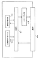
本実施の形態における通知装置であるプレゼンスサーバ100の通知条件設定動作について図3と図4を用いて説明する。図3は、本実施の形態における通知装置(プレゼンスサーバ100)の装置構成図であり、図4は、本実施の形態におけるプレゼンスサーバ100の通知条件設定フローチャートである。
The notification condition setting operation of
まず、制御部301は通知条件と通知先URIを入力する画面を表示する命令を画面出力部306に送り(S101)、ユーザ130からの入力を待つ(S102)。ユーザ130から通知条件と通知先URIがキー入力部307に入力されるとその情報が制御部301へ送られる(S103)。ここでは通知条件として「携帯電話101が通話可能、もしくはPC102が現在ユーザに使用されており固定電話103が通話可能」という条件が入力され、通知先URIとしてPC104のURIが入力されたとする。通知条件と通知先URIの入力方法としては、予め設定された複数の通知条件や通知先URIの中から適当な条件やURIを選択するなど、様々な方法で実現可能である。
First, the
制御部301は入力された条件を通知条件のフォーマットに変換する(S104)。ここでは「sip:101@example.com:state=”standby” OR (sip:102@example.com:presence=”open” AND sip:103@example.com:state=”standby”)」という通知条件に変換する。なお、通知条件のフォーマットについてはXMLなど、その他のフォーマットでもよい。
The
制御部301は通知条件と通知先URIを通知条件保持部303に保存する(S105)。ここでは通知条件として「sip:101@example.com:state=”standby” OR (sip:102@example.com:presence=”open” AND sip:103@example.com:state=”standby”)」を保存し、通知先URIとしてはPC104のURIである「sip:104@example.com」を保存する。なお、通知条件保持部303は複数の通知条件と通知先URIを保持可能である。通知条件保持部303のデータ構造の詳細については後述の図10で説明する。
The
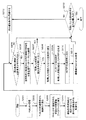
次にプレゼンスサーバ100のPUBLISH受信動作について図3と図5を用いて説明する。図5は、本発明の実施の形態1における通知装置(プレゼンスサーバ100)のPUBLISH受信フローチャートである。
Next, the PUBLISH reception operation of the
まず、通信部305がPUBLISHを受信し(S201)、受信したPUBLISHを制御部301に送る(S202)。制御部301はPUBLISHに記述された状態を状態管理データベース302に保存する(S203)。例えばPUBLISHに「sip:103@example.com:state=busy」という状態が記述されていた場合は、sip:103@example.comというURIが持つ状態項目”state”の状態値を”busy”に変更する。なお、状態管理データベースのデータ構造の詳細については、後述の図9で説明する。
First, the
制御部301は通知条件保持部303に保存されている最初の通知条件と通知先URIを取得する(S204)。ここで、PUBLISHによって更新された状態項目が通知条件に含まれていない場合は後述のS212ステップに進む(S205)。これは更新された状態項目が通知条件と関連が無い場合、NOTIFYを生成しないことを意味する。例えば取得した通知条件が「sip:101@example.com:state=”standby” OR (sip:102@example.com:presence=”open” AND sip:103@example.com:state=”standby”)」であり、PUBLISHに記述された状態が「sip:101@example.com:state=”busy”」である場合は、更新された状態項目が通知条件に含まれるので、S212ステップには進まない。
The
更新された状態項目が通知条件に含まれる場合、通知条件に記述された状態を状態管理データベース302から取得する(S206)。取得した状態が通知条件を満たさない場合は後述のS212ステップに進む(S207)。これは現在の状態が通知条件を満たさない場合はNOTIFYを生成しないことを意味する。 When the updated state item is included in the notification condition, the state described in the notification condition is acquired from the state management database 302 (S206). If the acquired state does not satisfy the notification condition, the process proceeds to step S212 to be described later (S207). This means that NOTIFY is not generated when the current state does not satisfy the notification condition.
例えば取得した状態が「sip:101@example.com:state=”off” sip:102@example.com:presence=”closed” sip:103@example.com:state=”busy”」であり、通知条件が「sip:101@example.com:state=”standby” OR (sip:102@example.com:presence=”open” AND sip:103@example.com:state=”standby”)」である場合は通知条件を満たさないのでS212ステップに進む。 For example, the acquired state is “sip: 101@example.com: state =“ off ”sip: 102@example.com: presence =“ closed ”sip: 103@example.com: state =“ busy ””, notification When the condition is “sip: 101@example.com: state =“ standby ”OR (sip: 102@example.com: present =“ open ”AND sip: 103@example.com: state =“ standby ”)” Does not satisfy the notification condition, the process proceeds to step S212.
一方、取得した状態が通知条件を満たす場合は、取得した状態と通知先URIをメッセージ生成部304に送り(S208)、メッセージ生成部304は通知先URIをRequest−URIに記述し、状態をボディ部に記述したNOTIFYを生成する(S209)。メッセージ生成部304は生成したNOTIFYを通信部305に送り(S210)、通信部305はNOTIFYを送信する(S211)。
On the other hand, if the acquired state satisfies the notification condition, the acquired state and the notification destination URI are sent to the message generation unit 304 (S208), and the
その後、制御部301は通知条件保持部303に保存されている通知条件をすべて処理したかを確認し、保持してある全ての通知条件について処理を行った場合は終了となる(S212)。まだ処理していない通知条件がある場合は、制御部301は通知条件保持部303から次の通知条件と通知先URIを取得し(S213)、S205ステップに戻って処理を継続する。
After that, the
次に、PC104のNOTIFY受信動作について図6と図7を用いて説明する。図6は、本発明の実施の形態1における通知装置から通知を受ける被通知装置であるPC104の装置構成図であり、図7は同PC104のNOTIFY受信フローチャートである。
Next, the NOTIFY reception operation of the
通信部203がNOTIFYを受信し(S301)、受信したNOTIFYを制御部201に送る(S302)。制御部201はNOTIFYに記述された状態を画面出力部202に表示する命令を送り、画面に状態を表示する(S303)。例えばNOTIFYに記述された状態が「sip:101@example.com:state=”off” sip:102@example.com:presence=”closed” sip:103@example.com:state=”standby”」である場合は、画面に「携帯電話:電源OFF、ユーザ:不在、居室電話:通話可能」というテキストメッセージを画面に表示させる。なお、画面表示形態はアイコン表示やその他の形態であってもよいし、画面に表示せずに音やその他の方法を使った通知方法であってもよい。
The
次に実施の形態1におけるNOTIFYメッセージの中身の詳細について説明する。なお、PUBLISHについては通常のSIPにおいて使用されるメッセージと同様なので説明を省略する。なお、図に記述したメッセージは説明に必要な部分以外については省略しているが、実際のメッセージには他のヘッダが存在する。 Next, details of the contents of the NOTIFY message in the first embodiment will be described. Since PUBLISH is the same as a message used in normal SIP, description thereof is omitted. The message described in the figure is omitted except for the parts necessary for the explanation, but the actual message has other headers.
図8は、本発明の実施の形態1における通知装置(プレゼンスサーバ100)から被通知装置(PC104)に送信されるNOTIFYのデータ構造図である。
FIG. 8 is a data structure diagram of NOTIFY transmitted from the notification device (presence server 100) to the notified device (PC 104) according to
NOTIFYのRequest−URIには、通知条件保持部の通知先URIに保持されたPC104のURIが記述される。Eventヘッダには、複数の状態の通知条件に関するイベントを表す”Multi−Filter”と記述する。ボディ部には状態管理データベース302から取得した状態が記述される。なお、状態は拡張ヘッダを使ってヘッダ部に記述してもよい。
In the NOTIFY Request-URI, the URI of the
次に、状態管理データベース302および通知条件保持部303のデータ構造について説明する。
Next, the data structures of the
最初に、状態管理データベース302の詳細について図9を用いて説明する。図9は、本発明の実施の形態1における通知装置の状態管理データベース302のデータ構造図である。状態管理データベース302は配下の機器のURIと状態を保持するデータベースであり、機器のURIと、それぞれの機器について1つ以上の状態項目、状態値の組を保持する。
First, details of the
図9に記述された例では、”sip:101@example.com”というURIを持つ機器は、状態項目”state”に対して、電源OFF状態を示す”off”という状態値を持ち、電波強度を表す”radio_intensity”という状態項目に対して、電波強度レベル3を示す”3”という状態値を持つということを示す。なお、保持する状態項目と状態値の組としてはネットワークへの接続状態を示す”network”など様々なものが考えられる。
In the example described in FIG. 9, a device having a URI “sip: 101@example.com” has a state value “off” indicating the power OFF state for the state item “state”, and the radio wave intensity. It is shown that the state item “radio_intensity” indicating “” has a state value “3” indicating the radio
次に、通知条件保持部303の詳細について図10を用いて説明する。図10は、本発明の実施の形態1における通知装置の通知条件保持部303のデータ構造図である。通知条件保持部303はユーザによって設定された通知条件と、通知先URIを保持する。通知条件と通知先URIについては複数保持することが可能である。
Next, details of the notification
図10に記述された例では、「sip:101@example.com:state=”standby” OR (sip:102@example.com:presence=”open” AND sip:103@example.com:state=”standby”)」という通知条件を満たした場合は「sip:104@example.com」に対して通知するということを示す。 In the example described in FIG. 10, “sip: 101@example.com: state =“ standby ”OR (sip: 102@example.com: present =“ open ”AND sip: 103@example.com: state =” When the notification condition “standby”) ”is satisfied, it indicates that notification is sent to“ sip: 104@example.com ”.
以上のように、実施の形態1では、ユーザ130がプレゼンスサーバ100に対して複数の機器の状態を論理条件で結んだ条件を通知条件として設定し、プレゼンスサーバ100は通知条件を満たすときだけPC104に対してNOTIFYを送信する例を示した。これによって、不要なNOTIFYが送信されることがなくなり、ネットワークリソースを有効に使用できるとともに、プレゼンスサーバ100とPC104のNOTIFY送受信負荷が軽減される。
As described above, in the first embodiment, the
(実施の形態2)
本発明の実施の形態2における通知装置および通知条件指定装置を含むネットワーク構成は、実施の形態1と、被通知装置であるPC104が本実施の形態の通知条件指定装置を兼ね、通知装置であるプレゼンスサーバ100に対し通知要求を出す点が異なる。本発明の実施の形態2では、PC104がプレゼンスサーバ100に対して「携帯電話101が通話可能、もしくはPC102が現在ユーザに使用されており固定電話が通話可能」という通知条件を指定した状態通知要求としてSUBSCRIBEを送り、プレゼンスサーバ100はSUBSCRIBEに記述された通知条件を満たすときのみ状態通知を行う例を示す。
(Embodiment 2)
The network configuration including the notification device and the notification condition designation device according to the second embodiment of the present invention is the notification device in which the
まず、図11を用いて、本発明の実施の形態2の通知装置と通知条件指定装置におけるメッセージフローを説明する。なお、図11では図2と同様に「200 OK」応答の記述を省略している。 First, a message flow in the notification device and the notification condition designation device according to the second embodiment of the present invention will be described with reference to FIG. In FIG. 11, the description of the “200 OK” response is omitted as in FIG.
携帯電話101、PC102、固定電話103はプレゼンスサーバ100に対してPUBLISHを送信し、それぞれが持つ状態を予め登録しておく。PC104はプレゼンスサーバ100に対して通知条件を記述したSUBSCRIBEを送信する。このとき通知条件としては「携帯電話101が通話可能、もしくはPC102が現在ユーザに使用されており固定電話が通話可能」という条件を表す「sip:101@example.com:state=”standby” OR (sip:102@example.com:presence=”open” AND sip:103@example.com:state=”standby”)」をSUBSCRIBEのSIPボディ部に記述しておく。プレゼンスサーバ100はSUBSCRIBEを受信すると、携帯電話101、PC102、固定電話103の現在の状態を記述したNOTIFYをPC104に対して送信する。
The
その後、携帯電話101、PC102、固定電話103はそれぞれが持つ状態が変化するたびにプレゼンスサーバ100に対してPUBLISHを送信する。プレゼンスサーバ100はPUBLISHを受信すると、携帯電話101、PC102、固定電話103の状態がSUBSCRIBEで指定された通知条件を満たしているか確認し、通知条件を満たさない場合はNOTIFYを送信せず、通知条件を満たすときのみPC104に対してNOTIFYを送信する。
Thereafter, the
次にPC104およびプレゼンスサーバ100の装置構成と動作について詳細を説明する。なお、実施の形態1と同様に簡単化のため各メッセージに対する「200 OK」応答の動作については説明を省略する。また、PC104のNOTIFY受信動作およびプレゼンスサーバ100のPUBLISH受信動作については実施の形態1と同様であるため、省略する。PC104のSUBSCRIBEの送信動作について、図12と図13を用いて説明する。図12は、本発明の実施の形態2における通知条件指定装置であり被通知装置でもあるPC104の装置構成図であり、図13は、同PC104のSUBSCRIBE送信フローチャートである。
Next, the device configurations and operations of the
図13において、制御部401は通知条件を入力する画面を表示する命令を画面出力部402に送り(S401)、ユーザ130からの入力を待つ(S402)。ユーザ130から通知条件が入力されるとその情報がキー入力部403から制御部401へ送られる(S403)。ここでは通知条件として「携帯電話101が通話可能、もしくはPC102が現在ユーザに使用されており固定電話103が通話可能」という条件が入力されたものとする。
In FIG. 13, the
制御部401は入力された条件を通知条件のフォーマットに変換する(S404)。ここでは「sip:101@example.com:state=”standby” OR (sip:102@example.com:presence=”open” AND sip:103@example.com:state=”standby”)」という通知条件に変換する。
The
制御部401は、変換した通知条件をメッセージ生成部404に送り(S405)、メッセージ生成部404は通知条件を記述したSUBSCRIBEを生成する(S406)。メッセージ生成部404は生成したSUBSCRIBEを通信部405に送り(S407)、通信部405は受け取ったSUBSCRIBEをプレゼンスサーバ100に向けて送信する(S408)。ここでプレゼンスサーバのアドレスはPC104に予め設定されていてもよいし、ユーザが入力画面から入力してもよい。SUBSCRIBEメッセージの中身に関する詳細は後述の図16で説明する。
The
次に、本実施の形態の通知装置であるプレゼンスサーバ100のSUBSCRIBE受信動作について図14と図15を用いて説明する。図14は、本発明の実施の形態2における通知装置(プレゼンスサーバ100)の装置構成図であり、図15は、同プレゼンスサーバ100のSUBSCRIBE受信フローチャートである。
Next, the SUBSCRIBE reception operation of the
図15において、通信部505が通知条件指定装置から送信されたSUBSCRIBEを受信し(S501)、受信したSUBSCRIBEを制御部501に送る(S502)。制御部501はSUBSCRIBEに記述された通知条件と通知先URIを通知条件保持部503に保存する(S503)。ここでは通知条件として「sip:101@example.com:state=”standby” OR (sip:102@example.com:presence=”open” AND sip:103@example.com:state=”standby”)」が記述されているのでこれを保存する。通知先URIとしてはSUBSCRIBEのContactヘッダに記述されたURIを保存する。通知条件保持部503のデータ構造の詳細については実施の形態1の通知条件保持部303と同様のため省略する。
In FIG. 15, the
その後、制御部501は状態管理データベース502から、通知条件に記述された機器の状態を取得する(S504)。ここではsip:101@example.comのstateと、sip:102@example.comのpresenceと、sip:103@example.comのstateの各状態を取得する。制御部501は取得した状態をメッセージ生成部504に送り(S505)、メッセージ生成部504は受け取った状態を記述したNOTIFYを生成する(S506)。メッセージ生成部504は生成したNOTIFYを通信部505に送り(S507)、通信部505はNOTIFYをPC104に送信する(S508)。
Thereafter, the
次に本発明の実施の形態2におけるSUBSCRIBEメッセージの中身の詳細について説明する。なお、PUBLISHについては実施の形態1と同様に通常のSIPにおいて使用されるメッセージと同様なので説明を省略する。また、NOTIFYメッセージの中身に関する詳細は実施の形態1と同様のため省略する。 Next, details of the contents of the SUBSCRIBE message in Embodiment 2 of the present invention will be described. Since PUBLISH is the same as the message used in normal SIP as in the first embodiment, the description thereof is omitted. Further, details regarding the contents of the NOTIFY message are the same as those in the first embodiment, and are therefore omitted.
SUBSCRIBEの中身の詳細について図16を用いて説明する。図16は、本発明の実施の形態2における通知条件指定装置(PC104)から通知装置(プレゼンスサーバ100)に送信される通知条件を示すSUBSCRIBEのデータフォーマット図である。なお、図8と同様に図に記述したメッセージは説明に必要な部分以外については省略している。 Details of the contents of SUBSCRIBE will be described with reference to FIG. FIG. 16 is a SUBSCRIBE data format diagram showing notification conditions transmitted from the notification condition designating device (PC 104) to the notification device (presence server 100) in the second embodiment of the present invention. As in FIG. 8, the messages described in the figure are omitted except for the parts necessary for the explanation.
SUBSCRIBEのRequest−URIには、携帯電話101、PC102、固定電話103のいずれかのURIが記述されてもよいし、PC104に予め設定された任意のアドレス(anonymous@anywhereなど)が記述されてもよい。Eventヘッダには、複数の機器の状態を指定したフィルタを示す”Multy−Filter”と記述する。ボディ部には通知条件を記述する。なお、通知条件は拡張ヘッダを使ってヘッダ部に記述してもよい。
The SUBSCRIBE Request-URI may describe any of the URIs of the
以上のように、実施の形態2では、通知条件指定装置として動作するPC104が通知装置であるプレゼンスサーバ100に対して複数の機器の状態を論理条件で結んだ条件を通知条件として記述したSUBSCRIBEを送信し、プレゼンスサーバ100は通知条件を満たすときだけNOTIFYを送信する例を示した。これによって、通知条件を通知条件指定装置であるPC104が指定することが可能となり、より適切なタイミングでNOTIFYが送信され、不要なNOTIFYが送信されることがなくなり、ネットワークリソースを有効に使用できるとともに、プレゼンスサーバ100とPC104のNOTIFY送受信負荷が軽減される。
As described above, in the second embodiment, the SUBSCRIBE in which the
なお、本実施の形態では、被通知装置が本発明の通知条件指定装置の機能を有する場合で説明したが、本発明はこれに限定されることはなく、個別に設置可能であることは言うまでもない。さらに、本発明は、例えば、図17に示すように、通知条件が「携帯電話101の電波強度が1以上で、PC102が現在ユーザに使用されている」というように、「以上」や「以下」といった不等号であっても実施可能である。
In the present embodiment, the case where the notified device has the function of the notification condition designating device of the present invention has been described. However, the present invention is not limited to this and can be installed individually. Yes. Further, the present invention, for example, as shown in FIG. 17, the notification condition is “above” or “below” such that the radio wave intensity of the
図17は、本発明の実施の形態2における通知条件指定装置から通知装置に送信される通知条件のデータフォーマット図である。SUBSCRIBEのヘッダ部については本実施の形態の先の場合と同様であるため説明を省略する。SUBSCRIBEのボディ部には通知条件が指定される。ここでは「携帯電話101の電波強度が1以上で、PC102が現在ユーザに使用されている」という通知条件を示す「sip:101@example.com:radio_intensity>=”1” AND sip:102@example.com:presence=”open”」というテキストが記述される。
FIG. 17 is a data format diagram of a notification condition transmitted from the notification condition designating device to the notification device according to Embodiment 2 of the present invention. Since the header part of SUBSCRIBE is the same as in the previous case of the present embodiment, description thereof is omitted. Notification conditions are specified in the body part of SUBSCRIBE. Here, “sip: 101@example.com: radio_intensity> =“ 1 ”AND sip: 102 @ example indicating a notification condition that“ the
プレゼンスサーバ100はSUBSCRIBEを受信すると、本実施の形態の先の例と同様の動作をし、SUBSCRIBEに記述された通知条件を満たすときのみNOTIFYを送信する。
When the
以上のように、PC104がプレゼンスサーバ100に対して「携帯電話101の電波強度が1以上で、PC102が現在ユーザに使用されている」という通知条件を指定した状態通知要求を送り、プレゼンスサーバ100はSUBSCRIBEに記述された通知条件を満たすときのみ状態通知を行う例を示した。以上のように、通知条件に状態項目と状態値の関係条件として不等号を使うことが可能である。
As described above, the
(実施の形態3)
図18は、本発明の実施の形態3における通知装置および通知条件指定装置を含むネットワーク構成図である。通知装置として動作するPC601、携帯電話602、通知条件指定装置および被通知装置として動作するPC603はネットワーク610に接続されている。PC601、携帯電話602はユーザ620が所有する機器である。PC603はユーザ630が所有する機器である。PC603はPC601、携帯電話602の状態の通知を望み、PC601もしくは携帯電話602のいずれかに状態通知要求を送る。ここではPC601に対して、「PC601の場所が会議室以外であり、携帯電話602が通話可能」という通知条件を指定した状態通知要求を送り、PC601は携帯電話602に対して状態通知要求を送って携帯電話602の状態を取得し、通知条件を満たすときのみ状態通知を行う例を示す。
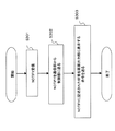
(Embodiment 3)
FIG. 18 is a network configuration diagram including a notification device and a notification condition specifying device according to
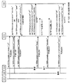
図19を用いて実施の形態3における通知装置および通知条件指定装置のメッセージフローを説明する。なお、図19では図2と同様に簡単化のため「200 OK」応答の記述を省略している。 The message flow of the notification device and the notification condition specifying device in the third embodiment will be described with reference to FIG. In FIG. 19, the description of the “200 OK” response is omitted for the sake of simplification as in FIG.
図19において、通知条件指定装置として動作するPC603は、通知装置として動作するPC601に対して通知条件を記述したSUBSCRIBEを送信する。このとき通知条件としては「PC601の場所が会議室以外であり、携帯電話602が通話可能」という条件を表す「NOT(sip:601@example.com:place=”meeting”) AND sip:602@example.com:state=”standby”」というメッセージをSIPボディ部に記述する。PC601は、SUBSCRIBEを受信すると、携帯電話602に対して基本状態の通知要求を行うSUBSCRIBEを送信する。
In FIG. 19, the
携帯電話602は、SUBSCRIBEを受信すると基本状態を記述したNOTIFYをPC601に送信する。PC601はNOTIFYを受信すると、取得した携帯電話602の基本状態とPC601自身が持つ場所状態を記述したNOTIFYをPC603に送信する。その後、携帯電話603は状態が変化するたびにPC601に対してNOTIFYを送信する。PC601は携帯電話603からNOTIFYを受信した場合、もしくはPC601自身の場所状態が変化した場合に通知条件を満たしているか確認し、通知条件を満たさない場合はNOTIFYを送信せず、通知条件を満たすときのみ被通知装置として動作するPC603に対してNOTIFYを送信する。
When receiving the SUBSCRIBE, the
ここで図18に戻り実施の形態3の詳細な説明をする。 Here, returning to FIG. 18, the third embodiment will be described in detail.
PC601は場所の状態を表す”place”という状態項目を持ち、placeは「居室/会議室/その他」を表す”Desk/meeting/other”という3つの状態値を持つ。場所状態の検出方法としてはPC601にRFID(Radio Frequency Identification)タグを搭載して、居室と会議室にRFID受信機を設置することにより、PC601の場所の状態を検出する方法など、様々な方法が考えられる。
The
携帯電話602は、実施の形態1の携帯電話101と同様に基本的な状態を表す”state”という状態項目を持ち、stateは「スタンバイ/電源オフ/通話中」を表す”standby/off/busy”という3つの状態値を持つ。ユーザ630はユーザ620の携帯電話に連絡することを望んでおり、ユーザ620が電話可能状態になったらPC603の画面に状態を表示することを望む。ここで電話可能状態とは「ユーザ620が会議室中以外で、携帯電話602が通話可能」という状態を示す。
The
ユーザ620の状態については所有するPC601の場所状態を「会議室以外」と指定し、携帯電話602については基本状態を「通話可能」と指定する。ユーザはPC603に通知条件を入力し、PC603は入力された条件を通知条件として記述したSUBSCRIBEをPC601に送信する。ここで通知条件としては「PC601の場所が会議室以外であり、携帯電話602の電波強度が1以上」という条件を指定する。PC603はPC601からのNOTIFYを受信するとその情報を画面に表示し、ユーザ620の状態をユーザ630に対して知らせる。なお、PC603の装置構成と動作については実施の形態2のPC104と同様であるため詳細な説明は省略する。
As for the state of the
PC601はPC603が送信したSUBSCRIBEを受信すると、そこに記述された通知条件を保持する。そして携帯電話602に対してSUBSCRIBEを送信して基本状態を取得する。携帯電話602の基本状態とPC601の場所状態が通知条件を満たさない場合はNOTIFYを送信せず、通知条件を満たす場合にはPC603に対してNOTIFYを送信する。PC601の動作の詳細については後述する。携帯電話602はPC601からのSUBSCRIBEを受信すると基本状態を記述したNOTIFYをPC601に送信する。
When the
次にPC601の動作について詳細を説明する。なお、PC601の装置構成については実施の形態2のプレゼンスサーバ100と同様である。また、実施の形態1、実施の形態2と同様に、簡単化のため各メッセージに対する「200 OK」応答の動作については説明を省略する。最初にPC601のSUBSCRIBE受信動作について図14と図20を用いて説明する。図20は、本発明の実施の形態4における通知装置であるPC601のSUBSCRIBE受信フローチャートである。本実施の形態の通知装置であるPC601の構成は、図14に示す本発明の実施の形態2における通知装置であるプレゼンスサーバ100の構成と同じである。
Next, details of the operation of the
図20において、通信部505が通知条件指定装置であるPC603から送信されたSUBSCRIBEを受信し(S601)、受信したSUBSCRIBEを制御部501に送る(S602)。制御部501はSUBSCRIBEに記述された通知条件と通知先URIを通知条件保持部503に保存する(S603)。ここでは通知条件が「NOT(sip:601@example.com:place=”meeting”) AND sip:602@example.com:state=”standby”」と記述されているものとし、これを保存する。通知先URIとしてはContactヘッダに記述されたURIを保存する。
In FIG. 20, the
その後、通知条件に記述された携帯電話602のURIをメッセージ生成部504に送る(S604)。メッセージ生成部504は受け取ったURIをRequest−URIに記述したSUBSCRIBEを生成し(S605)、それを通信部505に送る(S606)。通信部505はSUBSCRIBEを携帯電話602に送信し(S607)、SUBSCRIBEに対するNOTIFYの受信を待つ(S608)。
Thereafter, the URI of the
携帯電話602からのNOTIFYを通信部505が受信すると(S609)、通信部505は受信したNOTIFYを制御部501に送る(S610)。制御部501はNOTIFYに記述された状態を状態管理データベース502に保存する(S611)。例えばNOTIFYに「sip:602@example.com:state=”busy」という状態が記述されていた場合は、情報管理データベース502のsip:602@example.comというURIが持つ状態項目”state”の状態値を”busy”に変更する。
When the
その後、制御部501はPC603から送信されたNOTIFYの通知条件に記述された機器の状態を状態管理データベース502から取得する(S612)。例えば、状態条件が「NOT(sip:601@example.com:place=”meeting”) AND sip:602@example.com:state=”standby”」である場合はsip:601@example.comのplaceとsip:602@example.comのstateの各状態を取得する。なお、PC601自身の状態については状態が変化するたびに状態管理データベース502に保存されるものとする。
Thereafter, the
制御部501は取得した状態をメッセージ生成部504に送り(S613)、メッセージ生成部504は状態を記述したNOTIFYを生成する(S614)。メッセージ生成部504は生成したNOTIFYを通信部505に送り(S615)、通信部505はNOTIFYを被通知装置であるPC603に送信する(S616)。
The
次にPC601のNOTIFY受信動作について図14と図21を用いて説明する。図21は、本発明の実施の形態3における通知装置であるPC601のNOTIFY受信フローチャートである。なお、図21が示す動作は携帯電話602からの最初のNOTIFY(SUBSCRIBEに対するNOTIFY)の動作とは異なる。最初のNOTIFYについては図20のフローチャートに示された動作を行う。
Next, the NOTIFY reception operation of the
図21にて、通信部505が携帯電話602からのNOTIFYを受信し(S701)、受信したNOTIFYを制御部501に送る(S702)。制御部501はNOTIFYに記述された状態を状態管理データベース502に保存する(S703)。ここで、S704からS713までのステップは、実施の形態1におけるS204からS213までのステップと同様であるため説明を省略する。なお、S704からS713までのステップは、通知装置であるPC601自身の状態が変化し、状態管理データベース502に保存されている状態を変更した場合にも実行され、必要に応じてNOTIFYが生成される。
In FIG. 21, the
以上のように実施の形態3では、通知条件指定装置であるPC603が、通知装置であるPC601に対して通知条件を記述したSUBSCRIBEを送信し、PC601は通知条件に記述された状態を取得するために携帯電話602にSUBSCRIBEを送信し状態を取得し、通知条件を満たすときだけ被通知装置であるPC603にNOTIFYを送信する例を示した。これによって、プレゼンスサーバが無い場合でも通知条件を指定することができ、ネットワークリソースを有効に使用できるとともに、通知装置であるPC601と被通知装置であるPC603のNOTIFY送受信負荷が軽減される。また、実施の形態3のような構成をとることにより、サーバメンテナンスの必要がなくなる。
As described above, in the third embodiment, the
以上のように、本発明にかかる通知装置、通知条件指定装置および状態通知方法は、複数の状態条件および状態条件間の論理条件で通知タイミングを指定することによって、不要な通知情報が送信されることが無くなり、通信媒体を有効に使用できるとともに、通知情報送受信負荷が軽減されるという効果を有し、機器もしくは機器のユーザの状態を通知する通知装置、通知条件指定装置として、特にプレゼンスサービスや機器の状態管理サービスにおけるサーバ等として有用である。 As described above, in the notification device, the notification condition specifying device, and the state notification method according to the present invention, unnecessary notification information is transmitted by specifying a notification timing with a logical condition between a plurality of state conditions and state conditions. The communication device can be used effectively, the notification information transmission / reception load is reduced, and the notification device for notifying the state of the device or the user of the device, the notification condition designating device, It is useful as a server or the like in a device status management service.
100 プレゼンスサーバ
101、603 携帯電話
102、104、601、603 PC
103 固定電話
110、610 ネットワーク
120、130、620、630 ユーザ
201、301、401、501 制御部
202、306、402 画面出力部
307、403 キー入力部
304、404、504 メッセージ生成部
203、305、405、505 通信部
302、502 状態管理データベース
303、503 通知条件保持部
100
103
Claims (15)
15. The status notification method according to claim 12, wherein the notification condition reception step uses SIP for reception of the notification condition.
Priority Applications (1)
| Application Number | Priority Date | Filing Date | Title |
|---|---|---|---|
| JP2005050440A JP2006238112A (en) | 2005-02-25 | 2005-02-25 | Notification apparatus, notification condition designating apparatus and state notification method |
Applications Claiming Priority (1)
| Application Number | Priority Date | Filing Date | Title |
|---|---|---|---|
| JP2005050440A JP2006238112A (en) | 2005-02-25 | 2005-02-25 | Notification apparatus, notification condition designating apparatus and state notification method |
Publications (2)
| Publication Number | Publication Date |
|---|---|
| JP2006238112A true JP2006238112A (en) | 2006-09-07 |
| JP2006238112A5 JP2006238112A5 (en) | 2007-12-13 |
Family
ID=37045269
Family Applications (1)
| Application Number | Title | Priority Date | Filing Date |
|---|---|---|---|
| JP2005050440A Withdrawn JP2006238112A (en) | 2005-02-25 | 2005-02-25 | Notification apparatus, notification condition designating apparatus and state notification method |
Country Status (1)
| Country | Link |
|---|---|
| JP (1) | JP2006238112A (en) |
Cited By (8)
| Publication number | Priority date | Publication date | Assignee | Title |
|---|---|---|---|---|
| JP2008306623A (en) * | 2007-06-11 | 2008-12-18 | Yamaha Corp | Network communication system |
| JPWO2008139566A1 (en) * | 2007-05-08 | 2010-07-29 | 富士通株式会社 | Information communication system, information communication method, information communication apparatus, and computer program |
| JP2010537307A (en) * | 2007-08-21 | 2010-12-02 | サムスン エレクトロニクス カンパニー リミテッド | System and method for controlling SIP-based event notification with reference to subscriber preference |
| JP2011501586A (en) * | 2007-10-31 | 2011-01-06 | テレフオンアクチーボラゲット エル エム エリクソン(パブル) | Payload compression for session initiation protocol messages |
| JP2011511529A (en) * | 2008-01-28 | 2011-04-07 | テレフオンアクチーボラゲット エル エム エリクソン(パブル) | Presence throttle |
| JP2014233055A (en) * | 2013-05-30 | 2014-12-11 | 富士ゼロックス株式会社 | Information processing device and information processing program |
| KR101490680B1 (en) * | 2008-10-30 | 2015-02-09 | 에스케이플래닛 주식회사 | Method, Apparatus and System for Providing Track and Trace Service Using Radio Frequency Identification |
| JP2016025463A (en) * | 2014-07-18 | 2016-02-08 | トヨタ自動車株式会社 | Communication method in radio communication system, radio communication system, radio connection provision device, and radio communication device |
-
2005
- 2005-02-25 JP JP2005050440A patent/JP2006238112A/en not_active Withdrawn
Cited By (13)
| Publication number | Priority date | Publication date | Assignee | Title |
|---|---|---|---|---|
| JP5467866B2 (en) * | 2007-05-08 | 2014-04-09 | 富士通株式会社 | Information communication system, information communication method, information communication apparatus, and computer program |
| JPWO2008139566A1 (en) * | 2007-05-08 | 2010-07-29 | 富士通株式会社 | Information communication system, information communication method, information communication apparatus, and computer program |
| JP2008306623A (en) * | 2007-06-11 | 2008-12-18 | Yamaha Corp | Network communication system |
| JP2010537307A (en) * | 2007-08-21 | 2010-12-02 | サムスン エレクトロニクス カンパニー リミテッド | System and method for controlling SIP-based event notification with reference to subscriber preference |
| US9553940B2 (en) | 2007-08-21 | 2017-01-24 | Samsung Electronics Co., Ltd | System and method for controlling SIP-specific event notification according to preference of subscriber |
| JP2011501586A (en) * | 2007-10-31 | 2011-01-06 | テレフオンアクチーボラゲット エル エム エリクソン(パブル) | Payload compression for session initiation protocol messages |
| JP2011511529A (en) * | 2008-01-28 | 2011-04-07 | テレフオンアクチーボラゲット エル エム エリクソン(パブル) | Presence throttle |
| KR101490680B1 (en) * | 2008-10-30 | 2015-02-09 | 에스케이플래닛 주식회사 | Method, Apparatus and System for Providing Track and Trace Service Using Radio Frequency Identification |
| JP2014233055A (en) * | 2013-05-30 | 2014-12-11 | 富士ゼロックス株式会社 | Information processing device and information processing program |
| US10205793B2 (en) | 2013-05-30 | 2019-02-12 | Fuji Xerox Co., Ltd. | Information processing apparatus, information processing method, and non-transitory computer readable medium |
| US11218557B2 (en) | 2013-05-30 | 2022-01-04 | Fujifilm Business Innovation Corp. | Information processing apparatus, information processing method, and non-transitory computer readable medium |
| US12088680B2 (en) | 2013-05-30 | 2024-09-10 | Fujifilm Business Innovation Corp. | Information processing apparatus, information processing method, and non-transitory computer readable medium |
| JP2016025463A (en) * | 2014-07-18 | 2016-02-08 | トヨタ自動車株式会社 | Communication method in radio communication system, radio communication system, radio connection provision device, and radio communication device |
Similar Documents
| Publication | Publication Date | Title |
|---|---|---|
| CA2571413C (en) | Method, system and computer program to enable querying of resources in a certain context by definition of sip event package | |
| US7293271B2 (en) | Systems and methods for event semantic binding in networks | |
| CN101989959B (en) | Group management method and system in interworking system | |
| EP1872522B1 (en) | System and method for enabling asynchronous push-based applications on a wireless device | |
| EP1964357B1 (en) | Content aggregation service for mobile environment | |
| JP2006238112A (en) | Notification apparatus, notification condition designating apparatus and state notification method | |
| US9634865B2 (en) | Method of providing quick answer service in SIP message service system | |
| US20060123116A1 (en) | Service discovery using session initiating protocol (SIP) | |
| US20030095540A1 (en) | Web services push gateway | |
| EP2207305A1 (en) | A method and a system for address book processing | |
| ZA200700120B (en) | Method, system and computer program to enable semantic mediation for sip events through support of dynamicall binding to and changing of application semantics of si events | |
| EP2058984A2 (en) | UPnP-based network system and control method thereof based on an extension header | |
| KR20100057096A (en) | Active profile selection | |
| JP2008503952A5 (en) | ||
| WO2006000865A1 (en) | Method, system and computer program to enable sip event-based discovery of services and content within a community built on context information | |
| JP2009510863A (en) | Group communication in communication systems | |
| EP1872527B1 (en) | System and method for enabling group subscription for asynchronous push-based applications on a wireless device | |
| KR101973531B1 (en) | Method and apparatus for automatically sharing applications between multiple clients | |
| Gomes et al. | Xmpp based context management architecture | |
| JP4531593B2 (en) | Notification device, notified device, and status notification method | |
| KR20090087791A (en) | Converged ip messaging service system and method for interworking with non-converged ip messaging services | |
| JP2020096273A (en) | Sorting system and sorting method | |
| KR101595128B1 (en) | .method and apparatus for data oriented communication service | |
| JP2008103779A (en) | Event issuing server | |
| KR20120021216A (en) | Method and apparatus for sharing memo using universal plug and play telephony |
Legal Events
| Date | Code | Title | Description |
|---|---|---|---|
| A521 | Written amendment |
Effective date: 20071029 Free format text: JAPANESE INTERMEDIATE CODE: A523 |
|
| A621 | Written request for application examination |
Free format text: JAPANESE INTERMEDIATE CODE: A621 Effective date: 20071029 |
|
| RD01 | Notification of change of attorney |
Effective date: 20071113 Free format text: JAPANESE INTERMEDIATE CODE: A7421 |
|
| A761 | Written withdrawal of application |
Effective date: 20081226 Free format text: JAPANESE INTERMEDIATE CODE: A761 |