JP2006236053A - Handwritten information automatic totaling system - Google Patents
Handwritten information automatic totaling system Download PDFInfo
- Publication number
- JP2006236053A JP2006236053A JP2005050548A JP2005050548A JP2006236053A JP 2006236053 A JP2006236053 A JP 2006236053A JP 2005050548 A JP2005050548 A JP 2005050548A JP 2005050548 A JP2005050548 A JP 2005050548A JP 2006236053 A JP2006236053 A JP 2006236053A
- Authority
- JP
- Japan
- Prior art keywords
- original
- entry frame
- storage unit
- data
- entry
- Prior art date
- Legal status (The legal status is an assumption and is not a legal conclusion. Google has not performed a legal analysis and makes no representation as to the accuracy of the status listed.)
- Pending
Links
Images


Landscapes
- Character Input (AREA)
Abstract
Description
本発明は、役所などにおける申請書の自動電子登録システムや学習塾などの自動採点集計システムであり、画像読取時において、電子化された原本から、手書きにより追記された部分を抽出し、電子データの属性に応じた処理を施す技術に関する。 The present invention is an automatic scoring and counting system such as an automatic electronic registration system for application forms at a public office, etc., or a cram school, and at the time of image reading, a portion added by handwriting is extracted from an electronic original, and electronic data The present invention relates to a technique for performing processing according to the attributes of
近年、コンピュータが普及し、学校などで実施される試験の問題用紙及び解答用紙(以下「問題・解答用紙」という)や役所等において手続きの際に記入する記入用紙は電子データとして取扱われるようになっている。具体的には、問題・解答用紙や記入用紙をワードプロセッサソフトを使用してコンピュータで作成し、その電子データをコンピュータのハードディスク或いはその他の記憶媒体に保存する。そして、必要に応じて問題・解答用紙や記入用紙の電子データをワードプロセッサソフトを介して画像形成装置により紙媒体へ印字し、受験者や手続き者へ配布する。また、これらの修正もワードプロセッサソフトを介してその電子データを修正でき、手軽に取扱うことができるものとなっている。 In recent years, computers have become widespread, and question papers and answer papers (hereinafter referred to as “question / answer papers”) for examinations conducted at schools, etc., and entry forms to be filled in during procedures at government offices, etc. are handled as electronic data. It has become. Specifically, a question / answer sheet and an entry form are created by a computer using word processor software, and the electronic data is stored in a hard disk or other storage medium of the computer. Then, if necessary, the electronic data of the question / answer sheet and the entry form is printed on a paper medium by the image forming apparatus via the word processor software and distributed to the examinee and the procedure person. These corrections can also be easily handled by correcting the electronic data through the word processor software.
試験において受験者は、問題に対する解答を解答用紙の所定の欄に書き込み、解答の正否により試験の採点がされる。国家試験などの試験では、受験者の人数が多く、解答用紙の採点を行う者にとっては、その作業が負担となるばかりではなく、採点を誤ってしまうことがある。また、受験者の平均点や偏差値などの採点結果を手計算により求めなければならない。そのため、解答用紙を画像読取装置などで読み取り、コンピュータにより自動的に採点及び集計を行うシステムが必要とされていた。 In the examination, the examinee writes the answer to the question in a predetermined column of the answer sheet, and the test is scored based on whether the answer is correct. In exams such as national exams, the number of test takers is large, and for those who score answer sheets, the work is not only a burden, but the scores may be wrong. In addition, scoring results such as the average score and deviation value of examinees must be obtained manually. Therefore, there is a need for a system that reads an answer sheet with an image reading device or the like and automatically performs scoring and counting by a computer.
そこで、画像読取手段で問題用紙の画像を読み込んで画像記憶手段に記憶し、文字・罫線認識手段で認識した文字・罫線を問題用紙データ登録手段に、そして、正解入力手段により入力される正解データを問題用紙作画手段によって描画して画像出力手段により紙に印刷して出力でき、解答用紙を読み込んだときには、問題認識手段と解答認識手段が問題とその解答を認識して、採点手段によってその解答と正解登録手段に登録されている正解とを比較して採点し、その結果を採点結果出力手段により出力する採点及び問題用紙登録機能を有するデジタル複写機が提案されている(特許文献1)。この複写機においては、問題領域と正解領域を区別する方法として開始位置及び終了位置に特殊コードを埋め込む方法が適用されているが、問題数の増加に伴い、解答用紙にコードデータを数多く埋め込む必要があり、コードデータの汚れや欠損などにより、解答用紙を読み込んだ際に誤判定されてしまうといった危険性が増大するといった問題があった。 Therefore, the image of the question paper is read by the image reading means and stored in the image storage means, and the character / ruled line recognized by the character / ruled line recognition means is input to the question paper data registration means and the correct answer data input by the correct input means When the answer sheet is read, the problem recognizing means and the answer recognizing means recognize the problem and the answer, and the scoring means answers the answer. A digital copying machine having a scoring function and a question sheet registration function for comparing the correct answer registered in the correct answer registering means and scoring and outputting the result by the scoring result output means has been proposed (Patent Document 1). In this copying machine, a method of embedding a special code at the start position and end position is applied as a method for distinguishing between the problem area and the correct answer area. However, as the number of questions increases, it is necessary to embed a lot of code data on the answer sheet. There is a problem that the risk of misjudgment when an answer sheet is read increases due to dirt or missing code data.
また、行政機関などにおいて事務手続きの際に記入する申請書などの記入用紙は、所定の記入欄に要求されている項目を書き込むものとなっている。このことから、前述の複写機を応用することにより、数種類の記入用紙の管理をする場合には、各記入用紙の各記入欄の開始位置及び終了位置に特殊コードを埋め込み、記入欄に手書きで記入された項目を読み込むことにより管理する方法が考えられる。しかし、この場合においても、記入欄の数が増えると、記入用紙に沢山のコードデータを埋め込まなければならず、コードデータの汚れや欠損などにより、記入用紙を読み込んだ際に誤判定されてしまうばかりではなく、記入用紙の見栄えが悪くなってしまうといった問題があった。 In addition, an entry form such as an application form to be filled in during administrative procedures in an administrative organization or the like fills in the required items in a predetermined entry column. Therefore, when managing several types of entry forms by applying the above-mentioned copying machine, a special code is embedded at the start position and end position of each entry section of each entry form, and handwritten in the entry section. A method of managing by reading the entered items can be considered. However, even in this case, if the number of entry fields increases, it is necessary to embed a lot of code data in the entry form, and it is erroneously determined when the entry form is read due to dirt or missing code data. In addition to this, there was a problem that the appearance of the entry form deteriorated.
本発明はこのような問題点に鑑みなされたものであり、その目的とするところは、文字の認識精度を向上させ、画像読取装置により読み取った文書を自動的にデータ処理することができる手書き情報自動集計システムを提供することにある。 SUMMARY OF THE INVENTION The present invention has been made in view of such problems, and the object of the present invention is to improve handwriting information that can improve character recognition accuracy and automatically process a document read by an image reading apparatus. To provide an automatic counting system.
前記目的を達成するために、本発明の手書き情報自動集計システムは、所定の記入枠を有する原本フォーマットを作成する原本フォーマット作成手段を備える複数の端末装置と、当該複数の端末装置により作成された複数の原本フォーマットを格納すると共に、各原本フォーマットを識別するための原本IDを付与するサーバと、複数の前記端末装置の要求に従って前記サーバに格納された所定の原本フォーマットを記録用紙へ形成する出力装置と、前記原本フォーマットに従って記入された原本データにおける前記原本ID及び当該原本データの所定の記入枠の内容を読み取る画像読取装置とを備え、前記サーバは、前記原本データの原本IDに応じて前記所定の記入枠の記入データを処理することを特徴とするものである。 In order to achieve the above object, the handwritten information automatic tabulation system of the present invention is created by a plurality of terminal devices including an original format creation means for creating an original format having a predetermined entry frame, and the plurality of terminal devices. A server for storing a plurality of original formats and giving an original ID for identifying each original format, and an output for forming a predetermined original format stored in the server on a recording sheet in accordance with requests from the plurality of terminal devices And an image reading device that reads the original ID in the original data entered according to the original format and the contents of a predetermined entry frame of the original data, and the server responds to the original ID of the original data according to the original ID of the original data. It is characterized by processing entry data in a predetermined entry frame.
ここで、本発明における「原本フォーマット」とは、当該原本フォーマットの電子データと、記録用紙に形成された所定の記入枠を有する記入用紙或いは解答欄を有する試験問題などで何れも未記入の原本フォーマットとを指すものとする。そして、「原本データ」とは、記録用紙に形成された前記原本フォーマットの前記記入枠に手書きにより記入された当該原本フォーマットと、その電子データとを指すものとする。 Here, the “original format” in the present invention refers to the original data in which the electronic data in the original format and the test questions having the answering column or the answer sheet having the predetermined entry frame formed on the recording sheet are not yet entered. Refer to the format. The “original data” refers to the original format written by hand in the entry frame of the original format formed on the recording sheet and the electronic data.
このような本発明の手書き情報自動集計システムにおいて、前記端末装置は、本体と、モニターと、キーボードとから成る一般的なコンピュータであればよい。そして、前記モニターに関しては、当該モニター上に表示されているボタンをユーザが指で触れることにより作動するタッチパネル式のものを適用することもできる。 In such a handwritten information automatic counting system of the present invention, the terminal device may be a general computer including a main body, a monitor, and a keyboard. As the monitor, a touch panel type that operates when a user touches a button displayed on the monitor with a finger can be applied.
前記原本フォーマット作成手段は、文字や図形などを編集できるワードプロセッサソフトを使用し、所定の記入枠を有する記入用紙及び解答欄を有する試験問題(以下単に「試験問題」という)などを作成できるものであることが好ましい。前記ワードプロセッサソフトに関しては、一般的に使用されているソフトであっても、本システム専用のソフトの何れを適用してもよい。 The original format creation means is capable of creating a test question (hereinafter simply referred to as “test question”) having an answer sheet and an answer column using a word processor software capable of editing characters, figures and the like. Preferably there is. As the word processor software, either software that is generally used or software dedicated to the present system may be applied.
前記記入枠指定手段は、前記ワードプロセッサソフトにより作成された記入用紙及び試験問題の原本フォーマットにおいて、OCR処理させたい領域を指定できるものであればよく、例えば、矩形形状の記入枠における左上の座標及び右下の座標、即ち、対角関係の2点を指定する方法を適用することが好ましい。また、タッチパネル式のモニターを適用している場合には、モニター上に表示されている記入枠をユーザが指で触れることにより指定枠を指定させるものを適用することも可能である。 The entry frame designating means is not limited as long as it can designate an area to be subjected to OCR processing in the entry form created by the word processor software and the original format of the test question. For example, the upper left coordinates in the rectangular entry frame and It is preferable to apply a method of designating lower right coordinates, that is, two points in a diagonal relationship. In addition, when a touch panel monitor is applied, it is also possible to apply one in which a user designates a designated frame by touching an entry frame displayed on the monitor with a finger.
前記画像読取装置は、前記原本データに限らず、予め記録用紙などに形成されている記入用紙或いは試験問題の原本フォーマットを読み取り、電子データに変換できるものであればよく、一般的に使用されているスキャナやコピー機などの画像形成装置に装備されているスキャナ機能を前記画像読取装置として適用してもよい。 The image reading apparatus is not limited to the original data, and may be any apparatus that can read an entry form or a test question original format previously formed on a recording sheet and convert it into electronic data. A scanner function provided in an image forming apparatus such as a scanner or a copying machine may be applied as the image reading apparatus.
前記原本フォーマット作成手段により作成された原本フォーマットを記憶させる前記原本フォーマット記憶部は、複数のコンピュータを接続することによりネットワークが形成されている動作環境において、各コンピュータのハードディスク、或いは、当該コンピュータに記憶されている電子データを書き込むことができるフロッピディスク、CD−R、MOなどの記憶媒体に一時的に記憶させた後、前記サーバに前記フォーマットを記憶させることが好ましい。これにより、複数のコンピュータから前記フォーマットへアクセス可能に設定することができる。また、必要に応じ、前記原本フォーマット記憶部に記憶された原本フォーマットを基に前記出力装置により記録用紙へ原本を形成させることもできる。 The original format storage unit for storing the original format created by the original format creation means is stored in the hard disk of each computer or in the computer in an operating environment in which a network is formed by connecting a plurality of computers. It is preferable to store the format in the server after temporarily storing it in a storage medium such as a floppy disk, a CD-R, or an MO that can write electronic data. Thus, the format can be set to be accessible from a plurality of computers. If necessary, an original can be formed on a recording sheet by the output device based on the original format stored in the original format storage unit.
前記原本フォーマット記憶部には、複数の原本フォーマットを記憶させる必要があり、当該原本フォーマット記憶部に記憶させる際には、コンピュータで文書ファイルを扱うように、各原本フォーマットにファイル名を付けて記憶させれば済む。しかし、後述の前記コード付与手段により各原本フォーマットをコード化する際、ファイル名を直接コード化すると、コード自体のデータ量が増え、結果的にはコンピュータや前記サーバのハードディスクの容量を必要以上に使うことになってしまう。そこで、各原本フォーマットのファイル名とは別に各原本フォーマットを識別できる原本IDを付け、各原本IDを記憶させる原本ID記憶部を設けるとよい。そして、前記原本IDについては、例えば、「0000」、「0001」のように原本フォーマットが前記原本フォーマット記憶部に記憶された順番に番号を付け、各原本を識別できるものであればよい。また、原本IDは、前記原本フォーマット記憶部に原本フォーマットが記憶されると同時に自動的に原本IDが取得される方法、或いは、前記原本フォーマット作成手段により原本フォーマットを作成後、ユーザが前記サーバに申請することにより原本IDが取得される方法の何れかを適宜選択することが可能である。 The original format storage unit needs to store a plurality of original formats. When storing the original format storage unit, each original format is stored with a file name so that a document file can be handled by a computer. You can do it. However, when each original format is encoded by the code assigning means described later, if the file name is directly encoded, the data amount of the code itself increases, and as a result, the capacity of the hard disk of the computer or the server becomes larger than necessary. Will end up using it. Therefore, it is preferable to provide an original ID storage unit for storing each original ID by attaching an original ID for identifying each original format separately from the file name of each original format. The original ID may be any number that can identify each original by assigning numbers in the order in which the original formats are stored in the original format storage unit, such as “0000” and “0001”. Further, the original ID is stored in the original format storage unit at the same time as the original format is automatically acquired, or after the original format is created by the original format creating means, the user sends the original ID to the server. By applying, it is possible to appropriately select one of the methods for obtaining the original ID.
前記記入枠指定手段により各原本フォーマットの記入枠を指定する際に、当該記入枠が何を記入する枠であるかを示すような名称を付けていたのでは、ユーザの負担になってしまう。そこで、各記入枠を識別できる記入枠IDを付け、各記入枠IDを記憶させる記入枠ID記憶部を設けるとよい。この時、前記記入枠IDは、どの原本IDに属するかを明確にした上で記憶させなければならない。そして、前記記入枠IDは、前記記入枠指定手段により指定された順番、或いは、指定された記入枠の前記原本上における位置に応じ、例えば、「00」、「01」、「02」のように順次番号を付ければよく、前記記入枠指定手段により記入枠が指定されると同時に自動的に記入枠IDを付与する方法を適用することが好ましい。 When designating the entry frame of each original format by the entry frame designating means, if a name indicating what the entry frame is to be filled in is given, it becomes a burden on the user. Therefore, it is preferable to provide an entry frame ID storage unit that attaches an entry frame ID that can identify each entry frame and stores each entry frame ID. At this time, the entry frame ID must be stored after clarifying to which original ID it belongs. The entry frame ID is, for example, “00”, “01”, “02” depending on the order designated by the entry frame designating unit or the position of the designated entry frame on the original. It is preferable to apply a method of automatically assigning an entry frame ID at the same time as the entry frame is designated by the entry frame designating means.
前記記入枠指定手段により記入枠が指定される際には、OCR処理を行う都合上、前記記入枠IDの他に当該記入枠IDに対応した記入枠の原本上における位置を記憶させなければならない。そこで、前記記入枠指定手段により前記記入枠を指定する際に指定する当該記入枠の座標を記憶させる記入枠位置記憶部を設けるとよい。この時、前記記入枠位置記憶部に記憶させる座標は、矩形形状を有する前記記入枠の4点(頂点)の座標、好ましくは、当該記入枠において対角の位置関係にある2点の座標であればよい。このように、原本の記入枠の位置を前記記入枠位置記憶部に記憶させることにより、前記原本データを前記画像読取装置で読取った際に、当該原本データの記入枠の位置を特定することができ、前記記入枠に記載されている文字の認識精度を向上させることが可能となる。 When an entry frame is designated by the entry frame designation means, the position on the original entry frame corresponding to the entry frame ID must be stored in addition to the entry frame ID for the convenience of OCR processing. . Therefore, it is preferable to provide an entry frame position storage unit for storing the coordinates of the entry frame designated when the entry frame is designated by the entry frame designation means. At this time, the coordinates to be stored in the entry frame position storage unit are the coordinates of the four points (vertices) of the entry frame having a rectangular shape, preferably the coordinates of two points that are diagonally positioned in the entry frame. I just need it. Thus, by storing the position of the entry frame of the original in the entry frame position storage unit, the position of the entry frame of the original data can be specified when the original data is read by the image reading device. It is possible to improve the recognition accuracy of characters written in the entry box.
前記記入枠に記入された情報を集計するには、目的に応じて当該情報に何らかの処理が必要となる。そこで、前記記入枠指定手段により指定枠を指定する際に、当該記入枠に記入された情報の処理方法を記憶する処理方法記憶部を設け、前記サーバに予め処理方法をプログラミングさせるとよい。前記処理方法記憶部に記憶させる処理方法は、後述の集計データ記憶部へ情報を集計するように設定すればよく、例えば、氏名、住所、職業及び電子メール宛先については、それぞれ前記集計データ記憶部の氏名欄、住所欄、職業欄及び電子メール宛先欄に登録させ、前記電子メール宛先へ登録完了を通知するメールを送付するなどの方法を設定することができる。 In order to tabulate the information entered in the entry frame, some processing is required for the information depending on the purpose. Therefore, when the designated frame is designated by the entry frame designating means, a processing method storage unit for storing the processing method of the information entered in the entry frame may be provided, and the server may be programmed in advance. The processing method to be stored in the processing method storage unit may be set so as to total information in a total data storage unit described later. For example, for the name, address, occupation, and e-mail destination, the total data storage unit The name field, the address field, the occupation field, and the e-mail address field, and a method of sending a mail notifying the completion of registration to the e-mail address can be set.
前記コード付与手段は、前記原本ID記憶部に原本IDを記憶させた後、前記出力装置により当該原本を記録用紙へ形成させる際に、原本IDを識別できるようなバーコードやQRコードなどの2次元コードを原本フォーマットに付与できるものでなければならない。ここで、前記記入枠IDは前記原本IDに対応しており、更に、前記記入枠位置記憶部及び前記処理方法記憶部は前記記入枠IDにそれぞれ対応している。そのため、前記原本IDのみ原本へ付与すれば、前記画像読取装置により原本データを読取った際に、当該原本IDに属する記入枠に記入された情報を予めプログラミングされた処理方法により処理することが可能となる。 The code providing means stores the original ID in the original ID storage unit, and then forms a barcode, QR code, or the like that can identify the original ID when the original is formed on the recording sheet by the output device. The dimension code must be able to be given to the original format. Here, the entry frame ID corresponds to the original ID, and the entry frame position storage unit and the processing method storage unit respectively correspond to the entry frame ID. Therefore, if only the original ID is given to the original, when the original data is read by the image reading apparatus, it is possible to process the information written in the entry box belonging to the original ID by a pre-programmed processing method. It becomes.
前記集計データ記憶部は、前記処理方法記憶部に予め記憶されている処理方法に応じ、各記入枠に記入された情報を集計し、その集計結果を記憶できるものでなければならない。このように、前記サーバに前記集計データ記憶部を設けることにより、前記原本データを前記画像読取装置で読み取った際に、前記処理方法記憶部に記憶されている処理方法に従い前記原本データの所定の記入枠に記入されている情報を自動的に集計すると共に記憶し、当該サーバにデータベースを形成することができる。 The total data storage unit must be capable of totaling information entered in each entry box and storing the total result according to the processing method stored in advance in the processing method storage unit. In this way, by providing the total data storage unit in the server, when the original data is read by the image reading device, a predetermined value of the original data is determined according to the processing method stored in the processing method storage unit. Information entered in the entry box is automatically aggregated and stored, and a database can be formed on the server.
前述した前記原本フォーマット記憶部、前記原本ID記憶部、前記記入枠ID記憶部、前記記入枠位置記憶部、前記処理方法記憶部、前記コード付与手段及び前記集計データ記憶部は、前記サーバに設け、各記憶部は、当該サーバのハードディスクの記憶領域に確保するとよい。尚、前記サーバは、一般的なサーバマシンと同様に複数のCPU及びハードディスクを有するコンピュータを適用することが好ましい。 The original format storage unit, the original ID storage unit, the entry frame ID storage unit, the entry frame position storage unit, the processing method storage unit, the code assigning unit, and the total data storage unit are provided in the server. Each storage unit may be secured in a storage area of the hard disk of the server. The server is preferably a computer having a plurality of CPUs and hard disks as in a general server machine.
前記出力装置は、前記原本フォーマット記憶部に記憶されている前記原本フォーマットから記入用紙または試験問題、或いは、前記集計データ記憶部に記憶された集計結果を出力することができるものであればよい。そして、前記出力装置としては、電子写真方式或いはインクジェット方式の何れかの方式を適用している画像形成装置が好ましい。 The output device may be any device that can output an entry form or a test question from the original format stored in the original format storage unit, or a total result stored in the total data storage unit. The output device is preferably an image forming apparatus that employs either an electrophotographic system or an inkjet system.
本発明は、記入枠内に記入された手書き情報を処理することが可能であるため、手書きにより記入される記入枠を有する原本フォーマットを使用するもの、例えば、試験問題を自動的に採点する場合において適用することもできる。この場合においても、前記原本フォーマット作成手段により試験問題を作成し、当該試験問題の各設問の解答欄を前記記入枠指定手段により指定する。しかし、採点においては、各設問に対する解答と、解答者の手書きによる解答とを照合させ、正否を確認した後、各設問の配点に従い採点を行う必要がある。そこで、前記サーバには、各設問に対する解答及び配点を記憶させる解答・配点データ記憶部を備えるとよい。これにより、前記画像読取装置により試験問題の原本データを読取った際に、解答欄内に記入された手書きによる解答と、前記解答・配点データ記憶部に記憶されている解答とを照合し、正否を確認した後、採点を行うことが可能となる。更に、採点結果を前記集計データ記憶部に記憶させることにより、解答者別に採点結果のデータベースを形成することができる。 Since the present invention can process the handwritten information entered in the entry frame, it uses the original format having the entry frame filled in by handwriting, for example, when a test question is automatically scored. Can also be applied. Even in this case, a test question is created by the original format creation means, and an answer column for each question of the test question is designated by the entry frame designation means. However, in scoring, it is necessary to collate the answer to each question with the answer written by the answerer and check the correctness, and then score according to the score of each question. Therefore, it is preferable that the server includes an answer / scoring data storage unit that stores answers and scoring points for each question. As a result, when the original data of the test question is read by the image reading device, the handwritten answer entered in the answer column is collated with the answer stored in the answer / scoring data storage unit. After confirming, it becomes possible to score. Further, by storing the scoring results in the total data storage unit, a database of scoring results can be formed for each answerer.
以上のように構成される本発明の手書き情報集計システムによれば、文字の認識精度を向上させ、画像読取装置により読み取った文書を自動的にデータ処理することが可能となる。 According to the handwritten information totalizing system of the present invention configured as described above, the character recognition accuracy can be improved, and the document read by the image reading apparatus can be automatically processed.
以下添付図面に基づいて本発明の手書き情報自動集計システムを詳細に説明する。 The handwritten information automatic counting system of the present invention will be described in detail below with reference to the accompanying drawings.
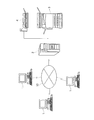
本発明の手書き情報自動集計システムの概略図を示しているのが図1である。本システムは、原本フォーマットを作成し、原本フォーマットにおける記入枠を指定するための複数(本図では3台)のパーソナルコンピュータ(端末装置)1と、パーソナルコンピュータ1で作成された原本フォーマットを記憶し、予めプログラミングされている処理方法に従って原本データを集計するサーバ2と、パーソナルコンピュータ1で作成した原本フォーマット、或いはサーバ2で集計された結果を記録用紙に形成する出力装置3と、予め作成され、記録用紙に形成されている原本フォーマット、或いは手書きにより記入された原本データを読取る画像読取装置4とから構成されている。そして、パーソナルコンピュータ1と、サーバ2とは情報通信ネットワーク10により接続され、出力装置3及び画像読取装置4は、それぞれLANケーブルなどにより直接サーバ2と接続されている。
FIG. 1 shows a schematic diagram of the handwritten information automatic tabulation system of the present invention. This system creates an original format and stores a plurality (three in the figure) of personal computers (terminal devices) 1 for designating entry frames in the original format and the original format created by the personal computer 1. A
本システムにおいて、情報通信ネットワーク10は、例えば、TCP/IPプロトコルを用いたものや(インタネット、イントラネット、エクストラネット)、その他のプロトコルを適用しているものを使用することができる。また、情報通信ネットワーク10の形態としては、有線によるもの或いは無線によるものでもよい。更に、端末装置としては、パーソナルコンピュータ1の他、他の形態のデータ通信機能を有するコンピュータ、例えば、ワークステーション、(データ通信機能付き)PDAなどを適用することが可能である。これら端末装置の何れを適用する場合であっても、原本を作成するためのワードプロセッサソフト、或いは専用ソフトを作動させることができるものでなければならない。尚、本図において、出力装置3及び画像読取装置4は、それぞれ別々にサーバ2と接続されているが、複写機能と、スキャナ機能とを備えたフルカラー複合機を適用する場合には、フルカラー複合機1台をサーバ2と接続する構成とすることもできる。
In this system, the
本発明において出力装置として適用される電子写真方式を用いたカラー画像形成装置の概略構成図を示しているのが図2である。本概略構成図は、接触帯電器で感光体表面を帯電した後、レーザ光線の照射により静電潜像を形成し、この静電潜像をトナーにより現像するゼログラフィエンジンをイエロー、マゼンタ、シアン、ブラックの各色について備えたタンデム型のカラー電子写真方式の画像形成装置のIOT(イメージアウトプットターミナル:画像出力部)の概要が示されている。尚、図中では画像形成装置の画像処理部などは省略している。 FIG. 2 shows a schematic configuration diagram of a color image forming apparatus using an electrophotographic system applied as an output device in the present invention. In this schematic configuration diagram, the surface of the photoconductor is charged by a contact charger, an electrostatic latent image is formed by irradiation with a laser beam, and the xerographic engine that develops the electrostatic latent image with toner is yellow, magenta, cyan. 1 shows an overview of an IOT (image output terminal: image output unit) of a tandem color electrophotographic image forming apparatus provided for each color of black. In the figure, the image processing unit of the image forming apparatus is omitted.
この画像形成装置のIOTは、図中矢印Aの方向にて回転する4つの感光体31Y、31M、31C、31Kと、この各感光体の表面を帯電する接触帯電器32Y、32M、32C、32Kと、帯電された各感光体表面を各色の画像情報に基づいて変調された露光光により露光し、各感光体上に静電潜像を形成するROS(レーザ出力部)33Y、33M、33C、33Kと、各感光体上の静電潜像を各色現像剤で現像して感光体上にトナー像を形成する現像器34Y、34M、34C、34Kと、感光体上の各色トナー像を中間転写体ベルト36に転写する一次転写器35Y、35M、35C、35Kと、中間転写体ベルト36上のトナー像を記録用紙Pに転写する二次転写器37と、記録用紙Pに転写されたトナー像を定着する定着器39と、記録用紙Pを収納する用紙トレイTと、各感光体の表面をクリーニングするクリーナ(図示せず)と、各感光体表面の残留電荷を除去する除電器(図示せず)と、中間転写体ベルト36表面をクリーニングするベルトクリーナ38とから構成されている。
The IOT of this image forming apparatus includes four
本構成図に示されている画像形成装置における画像形成動作としては、先ず、画像読取装置(図示せず)で原稿から読み取られた原画像信号、或いは外部のパーソナルコンピュータ(図示せず)などで作成された原画像信号は画像処理部(図示せず)に入力される。この入力画像信号は、各色の画像情報に分解された後、ROS(レーザ出力部)33Y、33M、33C、33Kに入力され、レーザ光線Lが変調される。そして、この変調されたレーザ光線Lは、接触帯電器32Y、32M、32C、32Kにより一様帯電された感光体31Y、31M、31C、31Kの表面に照射される。この各感光体表面にレーザ光線Lがラスタ照射されると、各感光体上にはそれぞれ入力画像信号に対応した静電潜像が形成される。続いて、各色現像器34Y、34M、34C、34Kにより各感光体上の静電潜像がトナーにより現像され、各感光体上にトナー像が形成される。各感光体上に形成されたトナー像は、各一次転写器35Y、35M、35C、35Kにより中間転写体ベルト36に転写される。この中間転写体ベルト36へトナー像の転写が終了した各感光体は、クリーナにより表面に付着した残留トナーなどの付着物がクリーニングされ、除電器により残留電荷が除去される。
As an image forming operation in the image forming apparatus shown in the configuration diagram, first, an original image signal read from a document by an image reading apparatus (not shown) or an external personal computer (not shown) is used. The created original image signal is input to an image processing unit (not shown). The input image signal is decomposed into image information of each color and then input to ROS (laser output units) 33Y, 33M, 33C, and 33K, and the laser beam L is modulated. The modulated laser beam L is applied to the surfaces of the
次に、中間転写体ベルト36上のトナー像は、二次転写器37により、用紙トレイから送られてくる記録用紙P上に転写された後、定着器39により記録用紙P上に転写されたトナー像が定着され所望の画像が得られる。記録用紙P上へのトナー像の転写が終了した中間転写体ベルト36は、ベルトクリーナ38により表面に付着した残留トナーなどの付着物がクリーニングされ、一回の画像形成動作が終了する。
Next, the toner image on the intermediate
本発明において適用される画像読取装置の概略構成図を示しているのが図3である。この画像読取装置4は、その上面に開口部を有し、この上面開口部には、原稿(図示せず)を載置するためのプラテンガラス41が取り付けられている。このプラテンガラス41上には、読み取るべき画像を下向きにした状態で、所定の位置に原稿が載置される。画像読取装置4の上部には、原稿をプラテンガラス41上に押圧するためのプラテンカバー42が、開閉自在に設けられている。
FIG. 3 shows a schematic configuration diagram of an image reading apparatus applied in the present invention. The
また、画像読取装置4の内部には、プラテンガラス41上に載置された原稿(図示せず)の画像を、照明する照射手段としてのランプ43と、ランプ43から照射された光を効率よく原稿面に集光するリフレクタ44と、原稿からの反射光像を水平方向に反射するフルレートミラー45と、このフルレートミラー45からの反射光像を折り返すように反射する2枚のハーフレートミラー46、47と、これら2枚のハーフレートミラー46、47からの反射光像を縮小結像する結像レンズ48と、遮光手段としてのサジタルストッパー49と、結像レンズ48によって結像された光像を電気信号に変換するCCD(Charge Coupled Device) イメージセンサ等からなる光電変換手段としてのラインイメージセンサ50とが設けられている。結像レンズ48としては、例えば、ダブルガウスタイプのレンズが用いられる。また、上記CCDイメージセンサ50として、カラー画像を読み取るためには、カラー画像をB(ブルー),G(グリーン),R(レッド)の3色で読み取るカラーCCDイメージセンサが用いられる。
Further, inside the
本構成において、ランプ43及びリフレクタ44と、フルレートミラー45とは、フルレートキャリッジ(図示せず)に搭載されており、このフルレートキャリッジは、副走査方向に沿って所定の速度Vで移動するように構成されている。また、2枚のハーフレートミラー46、47は、ハーフレートキャリッジ(図示せず)に搭載されており、このハーフレートキャリッジは、同じく副走査方向に沿って、フルレートキャリッジの半分の速度1/2・Vで移動するように構成されている。その結果、プラテンガラス41上に載置された原稿は、所定の速度で移動するランプ43、リフレクタ44及びフルレートミラー45と、2枚のハーフレートミラー46、47によって、光路長を変化させずに、結像レンズ48を介してCCDイメージセンサ50上に、その全面の画像が走査露光されるようになっている。
In this configuration, the
そして、原稿を読取る際には、プラテンガラス41上に載置された原稿の画像が、ランプ43から照射され、且つリフレクタ44によって集光された光によって照明され、当該原稿からの反射光像は、フルレートミラー45とハーフレートミラー46、47を介して、結像レンズ48によって、CCDイメージセンサ50上に縮小結像される。この時、結像レンズ48によってCCDイメージセンサ50上に縮小結像される原稿からの反射光像は、その一部がサジタルストッパー49で遮光され、CCDイメージセンサ50は、各々の画素ごとに入射光の強さに応じて光電変換を行い、これによって原稿画像に対応した画像信号(RGB信号)が得られる。
When the original is read, the image of the original placed on the
本発明の手書き情報自動集計システムのブロック図を示しているのが図4である。本図における手書き情報自動集計システムは、原本フォーマット作成手段1aと、記入枠指定手段1bと、サーバ2と、出力装置3と、画像読取装置4とから構成されている。図中の実線矢印は、これら構成物間のデータ及び作業の流れを示している。また、記録用紙P上に形成される原本フォーマットP1、原本ID付原本フォーマットP2及び集計結果表P4と、原本ID付原本フォーマットP2に手書きにより記入された原本データP3との流れは、区別の便宜上、点線矢印で示されている。尚、原本データP3Aについては、第2実施例において説明する。
FIG. 4 shows a block diagram of the handwritten information automatic tabulation system of the present invention. The handwritten information automatic tabulation system in this figure is composed of an original format creation means 1a, an entry frame designation means 1b, a
本図において、原本フォーマットP1は、予め記録用紙Pに形成される記入用紙或いは試験問題であって、記入枠或いは解答欄に手書きによって記入されていないものに該当し、画像読取装置4で読取ることにより原本フォーマットとしてサーバ2に記憶される。原本ID付原本フォーマットP2は、原本フォーマットをサーバ2に記憶させる際に当該原本フォーマットを識別するためのコードが付与されている記入用紙或いは試験問題であって、記入枠或いは解答欄に手書きによって記入されていないものに該当する。原本データP3は、記入用紙の原本ID付原本フォーマットP2の記入枠に手書きによって記入されているものに該当する。また、原本データP3Aは、試験問題の原本ID付原本フォーマットP2の解答欄に手書きによって記入されているものに該当する。集計結果表P4は、記録用紙Pに形成される記入用紙の集計結果或いは試験問題の採点結果を所定の書式により示されたものに該当する。
In this figure, the original format P 1 corresponds to an entry form or a test question previously formed on the recording sheet P, which is not entered by handwriting in the entry frame or answer column, and is read by the
図4のブロック図におけるサーバの構成の詳細を示しているのが図5である。サーバ2は、原本フォーマット記憶部21と、原本ID記憶部22と、記入枠ID記憶部23と、記入枠位置記憶部24と、処理方法記憶部25と、コード付与手段26と、集計データ記憶部27と、解答・配点データ記憶部28とから構成されている。尚、解答・配点データ記憶部28については、後述の第2実施例において説明する。
FIG. 5 shows details of the configuration of the server in the block diagram of FIG. The
原本データの記入枠内の情報からデータベースが形成されるまでを図式的に示しているのが図6である。分図(a)は、図4における原本データP3を示しており、原本データP3は、4つの記入枠F0、F1、F2、F3を有し、それぞれ氏名欄、住所欄、職業欄及び電子メール宛先欄となっている。また、原本データP3の左下には、原本IDを2次元コード化したコードCが形成されている。分図(b)には、サーバ2に記憶されている原本フォーマットの原本ID、記入枠ID、記入枠位置(2点の座標)及び各記入枠内の情報の処理方法が一覧表に示されている。分図(c)には、サーバ2(処理方法記憶部25)に記憶された処理方法に従い集計された各記入枠内の情報の集計結果がデータベースとして一覧表に示されている。
FIG. 6 schematically shows the process until the database is formed from the information in the entry frame of the original data. The partial diagram (a) shows the original data P 3 in FIG. 4, and the original data P 3 has four entry frames F 0 , F 1 , F 2 , F 3 , and a name field and an address field, respectively. , Occupation column and E-mail address column. Further, in the lower left of the original data P 3, the code C that is the two-dimensional code of the original ID is formed. In the partial diagram (b), the original ID of the original format stored in the
本発明の第1実施例におけるユーザによる作業の流れについて図7のフローチャート、図5及び図6を用いて説明する。先ず、ステップS1において、ユーザは、原本フォーマット作成手段1a(図5)により原本フォーマットを作成し、原本フォーマット記憶部21(図5)に原本フォーマットを記憶させる。そして、原本フォーマットの作成及び原本フォーマットの記憶が終了した後、ステップS2において、サーバ2に原本IDを申請し、作成した原本フォーマットの原本IDを取得する。この時、当該原本フォーマットの原本IDは原本ID記憶部22(図5)に記憶される。その後、ステップS3において、原本フォーマットにバーコード、或いはQRコードなどの2次元コードへコード化した原本IDデータがコード付与手段26により付与される(図6分図(a)コードC参照)。次に、ステップS4において、ユーザは、記入枠指定手段1b(図5)により、原本フォーマット上の記入枠のうち、OCR処理が必要となる記入枠を1つ指定すると、当該記入枠には記入枠IDが付けられ、当該記入枠IDが記入枠ID記憶部(図5)に記憶されると共に、当該記入枠の位置が記入枠位置記憶部24(図5)に記憶される。更に、ステップS5において、ステップS4で指定した記入枠について、当該記入枠内の情報の処理方法をプログラミングし、このプログラミングされた処理方法は、処理方法記憶部25(図5)に記憶される。ここで、指定する記入枠を追加する場合にはステップS4へ戻り(ステップS6)、指定する記入枠を追加しない場合には作業が終了する。
The work flow by the user in the first embodiment of the present invention will be described with reference to the flowchart of FIG. 7 and FIGS. 5 and 6. First, in step S1, the user creates an original format by the original format creation means 1a (FIG. 5), and stores the original format in the original format storage unit 21 (FIG. 5). After the creation of the original format and the storage of the original format are completed, in step S2, an original ID is applied to the
このように、図7のフローチャートに示されている作業を行うことにより、原本フォーマットは、図6分図(b)に示されているように、原本ID「0000」として原本ID記憶部22に記憶される。また、記入枠F0、F1、F2、F3は、それぞれ記入枠ID「00」、「01」、「02」、「03」として記入枠ID記憶部23に記憶される。そして、矩形形状を有する記入枠F0の位置は、記入枠F0の矩形における左上の頂点A及び右下の頂点Bの原本上での座標(図6分図(a)参照)がそれぞれ「100、100」及び「1800、400」として記入枠位置記憶部24に記憶され、記入枠F1、F2、F3も同様にして記入枠位置記憶部24に記憶される(図6分図(b)「座標A」、「座標B」欄参照)。更に、記入枠F0内の情報の処理方法は、「データベース氏名欄に登録」として処理方法記憶部25に記憶され、記入枠F1、F2、F3についても同様にして処理方法記憶部25に記憶される(図6分図(b)「処理方法」欄参照)。
Thus, by performing the work shown in the flowchart of FIG. 7, the original format is stored in the original
次に、原本フォーマットが手書きにより記入された原本データP3(図6分図(a))を処理方法記憶部25に記憶された処理方法に従い処理する場合には、先ず、原本データP3を画像読取装置4により読取り、原本データP3に形成されているコードCのデータと、原本ID記憶部22に記憶されている原本IDデータとが照合される。本実施例の場合であれば、照合した結果、読取られた原本データP3は、原本ID「0000」と識別され、記入枠ID「00」、「01」、「02」、「03」については、対角の位置関係にある座標A及び座標Bの2頂点により囲まれた矩形形状の領域内の手書き情報がそれぞれの処理方法に従い処理されると共に、随時集計される。そして、集計された結果は、集計データ記憶部27に記憶され、データベースが形成される(図6分図(c)参照)。本実施例の原本データP3については、記入枠F0、F1、F2、F3内の情報がそれぞれデータベースの氏名欄、住所欄、職業欄、電子メール宛先欄に登録されると共に記憶され、電子メール宛先欄に登録されている電子メール宛先へ登録完了を通知する電子メールが送信される。尚、集計データ記憶部27に記憶された集計結果を集計結果表P4(図4参照)として記録用紙へ形成する場合には、出力装置3へ集計データが送られる。
Next, when the original data P 3 (FIG. 6 (a)) in which the original format is entered by handwriting is processed according to the processing method stored in the processing
続いて、本発明を使用しているユーザが既に原本フォーマットの情報をサーバに記憶した原本について、記入枠の情報を追加し、原本フォーマットの情報を更新する流れについて図8のフローチャートを用いて説明する。先ず、ステップS11において、ユーザは、パーソナルコンピュータ1からサーバ2の原本ID記憶部22に原本IDの問い合わせをする。そして、問い合わせた原本IDに対応する原本情報をサーバ2から取得する(ステップS12)。
Subsequently, the flow of adding the information of the entry frame and updating the information of the original format with respect to the original whose information on the original format has already been stored in the server by the user using the present invention will be described with reference to the flowchart of FIG. To do. First, in step S <b> 11, the user inquires of the original ID from the personal computer 1 to the original
ここで、パーソナルコンピュータ1からユーザに記入枠の情報の追加有無が確認され(ステップS13)、記入枠の情報を追加する場合には、ステップS14において、ユーザはパーソナルコンピュータ1(記入枠指定手段1b)により、原本上の記入枠のうち、OCR処理が必要となる記入枠を1つ指定し、記入枠の位置が記入枠位置記憶部24に記憶される。更に、ステップS15において、ステップS14で指定した記入枠について、当該記入枠内の情報の処理方法をプログラミングし、このプログラミングされた処理方法は、処理方法記憶部25に記憶され、ステップS13に戻る。
Here, the personal computer 1 confirms whether or not entry frame information has been added to the user (step S13). When adding entry frame information, in step S14, the user selects the personal computer 1 (entry frame designation means 1b). ) Designates one entry frame that requires OCR processing from among the entry frames on the original, and the position of the entry frame is stored in the entry frame
一方、記入枠の情報を追加しない場合には、パーソナルコンピュータ1からユーザに、記憶された記入枠の修正有無が確認され(ステップS21)、記入枠を修正する場合には、ステップS22において、ユーザは記憶された記入枠を修正する(ステップS22)。そして、ステップS23において、当該記入枠の情報を更新し、ステップS13に戻る。ステップS13において、記入枠の情報の追加が無く、更には、ステップS21において記憶された記入枠の修正が無い場合には作業が終了する。 On the other hand, if the information on the entry frame is not added, the personal computer 1 confirms whether or not the stored entry frame is corrected (step S21). If the entry frame is to be corrected, the user is checked in step S22. Corrects the stored entry frame (step S22). In step S23, the information in the entry box is updated, and the process returns to step S13. If there is no addition of entry frame information in step S13, and if there is no correction of the entry frame stored in step S21, the operation ends.
解答が記入された試験問題の原本データの記入枠内の情報から自動的に試験が採点されるまでを図式的に示しているのが図9である。分図(a)は、図4における原本データP3Aを示しており、原本データP3Aは、4つの記入枠F0、F1、F2、F3を有し、それぞれ氏名欄、設問1解答欄、設問2解答欄及び設問3解答欄となっている。また、原本データP3Aの左下には、原本IDを2次元コード化したコードCが形成されている。分図(b)には、サーバ2に記憶されている試験問題の原本フォーマットの原本ID、記入枠ID、記入枠位置(2点の座標)及び各記入枠内の情報の処理方法が一覧表に示されている。分図(c)には、サーバ2(解答・配点データ記憶部28)に記憶されている各設問の解答及び配点が一覧表に示されている。そして、分図(d)には、サーバ2(処理方法記憶部25)に記憶された処理方法に従い採点された、試験問題の各原本データの採点結果がデータベースとして一覧表に示されている。
FIG. 9 schematically shows the process from the information in the entry frame of the original data of the test question in which the answer is entered until the test is automatically scored. The partial diagram (a) shows the original data P 3A in FIG. 4, and the original data P 3A has four entry boxes F 0 , F 1 , F 2 , F 3 , respectively. It is an answer column, a
試験問題に対する解答を自動的に採点する本発明の第2実施例おけるユーザによる作業の流れについて図10のフローチャート、図5及び図9を用いて説明する。先ず、ステップS31において、ユーザは、原本フォーマット作成手段1a(図5)により試験問題の原本フォーマットを作成し、原本フォーマット記憶部21(図5)に試験問題の原本フォーマットを記憶させる。そして、試験問題の原本フォーマットの作成が終了した後、ステップS32において、サーバ2に原本IDを申請し、作成した試験問題の原本フォーマットの原本IDを取得する。この時、当該原本フォーマットの原本IDは原本ID記憶部22(図5)に記憶される。その後、ステップS33において、原本フォーマットにバーコード、或いはQRコードなどの2次元コードへコード化した原本IDデータがコード付与手段26により付与される(図9分図(a)コードC参照)。次に、ステップS34において、ユーザは、記入枠指定手段1b(図5)により、原本フォーマット上の記入枠のうち、OCR処理が必要となる記入枠(本実施例においては、解答が手書きされる解答欄に相当)を1つ指定すると、当該記入枠には記入枠IDが付けられ、当該記入枠IDが記入枠ID記憶部(図5)に記憶されると共に、当該記入枠の位置が記入枠位置記憶部24(図5)に記憶される。更に、ステップS35において、ステップS34で指定した記入枠について、当該記入枠内の情報の処理方法をプログラミングし、このプログラミングされた処理方法は、処理方法記憶部25(図5)に記憶される。ここで、試験問題が複数の設問から構成される場合にはステップS34へ戻り(ステップS36)、設問の数に応じ記入枠の指定(ステップS34)及び記入枠内情報の処理方法のプログラミング(ステップS35)を繰り返す。そして、全ての設問の記入枠の指定を終了させた後、ステップS37において各設問の解答及び配点を解答・配点データ記憶部28(図5)に記憶させ、解答・配点データベースを作成し、作業が終了する。
The flow of work by the user in the second embodiment of the present invention for automatically scoring answers to test questions will be described with reference to the flowchart of FIG. 10 and FIGS. First, in step S31, the user creates an original format of the test question using the original format creation means 1a (FIG. 5), and stores the original format of the test question in the original format storage unit 21 (FIG. 5). After the creation of the original test question format is completed, in step S32, the
このように、図10のフローチャートに示されている作業を行うことにより、試験問題の原本フォーマットは、図9分図(b)に示されているように、原本ID「0000」として原本ID記憶部22に記憶される。また、記入枠F0、F1、F2、F3は、それぞれ記入枠ID「00」、「01」、「02」、「03」として記入枠ID記憶部23に記憶される。そして、矩形形状を有する記入枠F0の位置は、記入枠F0の矩形における左上の頂点A及び右下の頂点Bの原本上での座標(図9分図(a)参照)がそれぞれ「100、100」及び「1800、400」として記入枠位置記憶部24に記憶されており、記入枠F1、F2、F3も同様にして記入枠位置記憶部24に記憶されている(図9分図(b)「座標A」、「座標B」欄参照)。更に、記入枠F0内の情報の処理方法は、「データベース氏名欄に登録」として処理方法記憶部25に記憶され、記入枠F1、F2、F3についても同様にして処理方法記憶部25に記憶される(図9分図(b)「処理方法」欄参照)。
Thus, by performing the work shown in the flowchart of FIG. 10, the original format of the test question is stored as the original ID “0000” as shown in FIG. 9B (b). Stored in the
次に、試験問題の原本フォーマットが手書きにより記入された、つまり、解答が記入された原本データP3A(図9分図(a))を処理方法記憶部25に記憶された処理方法に従い処理し、解答・配点データ記憶部28に記憶された解答及び配点に基づき自動的に採点する場合には、先ず、原本データP3Aを画像読取装置4により読取り、原本データP3Aに形成されているコードCのデータと、原本ID記憶部22に記憶されている原本IDデータとが照合される。本実施例の場合であれば、照合した結果、読取られた原本データP3Aは、原本ID「0000」と識別され、記入枠ID「00」、「01」、「02」、「03」については、対角の位置関係にある座標A及び座標Bの2頂点により囲まれた矩形形状の領域内の手書き情報がそれぞれの処理方法に従い処理される。この時、記入枠F1、F2、F3、即ち、解答欄内の手書き情報については、データベースにおける各設問の解答欄に登録された後、各解答欄の手書き情報と、予め解答・配点データ記憶部28に記憶されている各設問の解答(図9分図(c)参照)とが照合され、正解である場合には、同じく予め解答・配点データ記憶部28に記憶されている各設問の配点(図9分図(c)参照)がデータベースの採点欄に入力されるのに対し、不正解である場合には、データベースの採点欄に「0」(ゼロ)が入力される。そして、最後の設問(本実施例においては設問3)の採点欄に配点が入力された後は、更に各採点欄に入力された点数から合計点が算出される。このようにして採点された結果は、集計データ記憶部27に記憶され、データベースが形成される(図9分図(d)参照)。従って、本実施例の原本データP3Aについては、記入枠F0、F1、F2、F3内の情報に基づき、解答者別に試験問題の採点結果が記憶される。尚、集計データ記憶部27に記憶された集計結果を集計結果表P4(図4参照)として記録用紙へ形成する場合には、出力装置3へ集計データが送られる。
Next, the original data P 3A (FIG. 9 (a)) in which the original format of the test question is entered by handwriting, that is, the answer is entered, is processed according to the processing method stored in the processing
このように、本発明の第1実施例及び第2実施例によれば、記入済或いは解答済の原本が画像読取装置4により読取られる際には、予め指定されている記入枠の領域についてのみOCR処理を行うので、集計データ記憶部27には手書きデータ、即ち、記入枠内の電子データ以外のものは記憶されることはない。従って、各原本における記入枠内の情報の集計或いは採点においては、集計データ記憶部27の記憶領域の使用領域を最小限に抑えることが可能となる。また、予め指定されている記入枠の領域の手書きデータについてのみOCR処理を行うため、記入枠内の文字の認識精度を向上させることができる。更に、予め各記入枠内の情報の処理方法をプログラミングし、当該処理方法を処理方法記憶部25に記憶させているため、自動的に各記入枠内の情報の集計や採点等を行うことが可能となる。
As described above, according to the first and second embodiments of the present invention, when the completed or answered original is read by the
また、本発明の第1実施例及び第2実施例のシステムは、複数のパーソナルコンピュータと、サーバとにより情報通信ネットワークを形成し、構成されている。そのため、第1実施例であれば、役所の部署内において、各部署員が使用する複数のパーソナルコンピュータと、サーバとを情報通信ネットワークにより接続し、更には当該サーバに出力装置及び画像読取装置を接続し、適用するとよい。この場合、各部署員は、各自のパーソナルコンピュータで記入用紙を作成後、当該記入用紙の電子データをサーバに記憶させ、必要に応じ出力装置により当該記入用紙を記録用紙へ形成させることができる。そして、手書きにより記入された記入用紙を画像読取装置により読取り、記入用紙に手書きされた情報を電子データとしてサーバに記憶させると共に、手書き情報を自動的に集計させることも可能である。また、記入用紙及び当該記入用紙に記入された手書き情報は、何れも電子データとして扱われるため、紙として保存する場合のような保管スペースを必要とせず、ペーパレス化を推進することができる。 The systems of the first and second embodiments of the present invention are configured by forming an information communication network by a plurality of personal computers and servers. Therefore, in the first embodiment, in the department of the government office, a plurality of personal computers used by each department member and a server are connected by an information communication network, and an output device and an image reading apparatus are connected to the server. Connect and apply. In this case, each department member can create an entry form with his / her personal computer, store the electronic data of the entry form in a server, and form the entry form on a recording form as required by the output device. It is also possible to read the handwritten entry form by the image reading device, store the information handwritten on the entry form as electronic data in the server, and automatically add the handwritten information. In addition, since both the entry form and the handwritten information entered on the entry form are handled as electronic data, a storage space is not required as in the case of saving the form as paper, and paperlessness can be promoted.
更に、第2実施例であれば、学校の職員室において、各教員が使用する複数のパーソナルコンピュータと、サーバとを情報通信ネットワークにより接続し、更には当該サーバに出力装置及び画像読取装置を接続し、適用することができる。この場合、各教員は、各自のパーソナルコンピュータで試験問題を作成後、当該試験問題の電子データをサーバに記憶させ、試験を実施する際に必要となる枚数だけ出力装置により当該試験問題を記録用紙へ形成させることが可能である。そして、各設問の解答が記入された試験問題を画像読取装置により読取り、各解答の情報を電子データとしてサーバに記憶させると共に、予めサーバに記憶させた各設問の解答及び配点に基づき自動的に採点させることができる。また、試験問題及び当該試験問題に記入された解答の情報は、何れも電子データとして扱うことができ、採点結果より平均点や標準偏差、更には、各教科の採点結果をひとつの集計結果表にまとめ、成績表を作成することが可能となる。 Further, in the second embodiment, in the school staff room, a plurality of personal computers used by each teacher and a server are connected by an information communication network, and an output device and an image reading device are connected to the server. And can be applied. In this case, each faculty member creates test questions on his / her personal computer, stores electronic data of the test questions in the server, and records the test questions on the recording device using the output device as many times as necessary when conducting the test. Can be formed. Then, a test question in which the answer of each question is entered is read by the image reading device, and information on each answer is stored in the server as electronic data, and automatically based on the answer and the score of each question stored in the server in advance. Can be scored. In addition, both the test questions and the answer information entered in the test questions can be handled as electronic data. From the scoring results, the average score and standard deviation, and further, the scoring results of each subject are stored in one tabulation result table. It is possible to create a gradebook.
1a・・・原本フォーマット作成手段、1b・・・記入枠指定手段、2・・・サーバ、21・・・原本フォーマット記憶部、22・・・原本ID記憶部、23・・・記入枠ID記憶部、24・・・記入枠位置記憶部、25・・・処理方法記憶部、26・・・コード付与手段、27・・・集計データ記憶部、28・・・解答・配点データ記憶部、3・・・出力装置、4・・・画像読取装置
DESCRIPTION OF
Claims (3)
前記サーバは、前記原本データの原本IDに応じて前記所定の記入枠の記入データを処理することを特徴とする手書き情報自動集計システム。 A plurality of terminal devices having original format creation means for creating an original format having a predetermined entry frame, and a plurality of original formats created by the plurality of terminal devices, and originals for identifying each original format A server for assigning an ID, an output device for forming a predetermined original format stored in the server in accordance with requests of the plurality of terminal devices on a recording sheet, the original ID in the original data entered according to the original format, and An image reading device that reads the contents of a predetermined entry frame of the original data,
The server processes the entry data of the predetermined entry frame according to the original ID of the original data.
前記サーバは、前記原本フォーマットを記憶する原本フォーマット記憶部と、前記原本IDを記憶する原本ID記憶部と、前記出力装置により前記原本フォーマットを記録用紙へ形成する際、前記原本ID記憶部に記憶された原本IDのコードを当該原本フォーマットへ付与するコード付与手段と、前記原本フォーマット毎に当該原本フォーマットの記入枠を識別するための記入枠IDを記憶する記入枠ID記憶部と、前記記入枠毎に当該記入枠の位置を記憶する記入枠位置記憶部と、前記記入枠毎に当該記入枠の記入データの処理方法を記憶する処理方法記憶部と、前記処理方法記憶部に記憶された処理方法に基づき前記記入枠の記入データを処理することにより集計されたデータを記憶する集計データ記憶部とを備えていることを特徴とする請求項1に記載の手書き情報自動集計システム。 The terminal device includes an entry frame designating unit for designating the entry frame when creating the original format,
The server stores an original format storage unit that stores the original format, an original ID storage unit that stores the original ID, and stores the original format on a recording sheet by the output device in the original ID storage unit. Code providing means for assigning the code of the original ID to the original format, an entry frame ID storage unit for storing an entry frame ID for identifying an entry frame of the original format for each original format, and the entry frame An entry frame position storage unit that stores the position of the entry frame every time, a processing method storage unit that stores a processing method of entry data of the entry frame for each entry frame, and a process stored in the processing method storage unit And a total data storage unit for storing data totaled by processing the input data of the input frame based on the method, Strokes rollup system according to claim 1 that.
前記サーバは、解答・配点データ記憶部を備えていることを特徴とする請求項2に記載の手書き情報自動集計システム。 In the case where the original format is a test question in which an answer is written in a predetermined entry frame,
The handwritten information automatic tabulation system according to claim 2, wherein the server includes an answer / scoring data storage unit.
Priority Applications (1)
| Application Number | Priority Date | Filing Date | Title |
|---|---|---|---|
| JP2005050548A JP2006236053A (en) | 2005-02-25 | 2005-02-25 | Handwritten information automatic totaling system |
Applications Claiming Priority (1)
| Application Number | Priority Date | Filing Date | Title |
|---|---|---|---|
| JP2005050548A JP2006236053A (en) | 2005-02-25 | 2005-02-25 | Handwritten information automatic totaling system |
Publications (2)
| Publication Number | Publication Date |
|---|---|
| JP2006236053A true JP2006236053A (en) | 2006-09-07 |
| JP2006236053A5 JP2006236053A5 (en) | 2010-05-06 |
Family
ID=37043628
Family Applications (1)
| Application Number | Title | Priority Date | Filing Date |
|---|---|---|---|
| JP2005050548A Pending JP2006236053A (en) | 2005-02-25 | 2005-02-25 | Handwritten information automatic totaling system |
Country Status (1)
| Country | Link |
|---|---|
| JP (1) | JP2006236053A (en) |
Cited By (3)
| Publication number | Priority date | Publication date | Assignee | Title |
|---|---|---|---|---|
| JP2010086244A (en) * | 2008-09-30 | 2010-04-15 | Toppan Forms Co Ltd | Information collection system |
| JP2010086243A (en) * | 2008-09-30 | 2010-04-15 | Toppan Forms Co Ltd | Information collection system |
| JP2021016078A (en) * | 2019-07-11 | 2021-02-12 | 株式会社リコー | Information processing system, information processing method, and device |
Citations (2)
| Publication number | Priority date | Publication date | Assignee | Title |
|---|---|---|---|---|
| JPH08186672A (en) * | 1994-12-30 | 1996-07-16 | Ricoh Co Ltd | Digital copying machine with function marking and registering examination paper |
| JPH09223007A (en) * | 1996-02-19 | 1997-08-26 | Fuji Xerox Co Ltd | Input sheet system |
-
2005
- 2005-02-25 JP JP2005050548A patent/JP2006236053A/en active Pending
Patent Citations (2)
| Publication number | Priority date | Publication date | Assignee | Title |
|---|---|---|---|---|
| JPH08186672A (en) * | 1994-12-30 | 1996-07-16 | Ricoh Co Ltd | Digital copying machine with function marking and registering examination paper |
| JPH09223007A (en) * | 1996-02-19 | 1997-08-26 | Fuji Xerox Co Ltd | Input sheet system |
Cited By (4)
| Publication number | Priority date | Publication date | Assignee | Title |
|---|---|---|---|---|
| JP2010086244A (en) * | 2008-09-30 | 2010-04-15 | Toppan Forms Co Ltd | Information collection system |
| JP2010086243A (en) * | 2008-09-30 | 2010-04-15 | Toppan Forms Co Ltd | Information collection system |
| JP2021016078A (en) * | 2019-07-11 | 2021-02-12 | 株式会社リコー | Information processing system, information processing method, and device |
| JP7342472B2 (en) | 2019-07-11 | 2023-09-12 | 株式会社リコー | Information processing system, information processing method |
Similar Documents
| Publication | Publication Date | Title |
|---|---|---|
| CN100525363C (en) | Automatic grading apparatus, method | |
| JP3693691B2 (en) | Image processing device | |
| US9582484B2 (en) | Methods and systems for filling forms | |
| CN109712456A (en) | System is intelligently read and made comments in a kind of student's papery operation based on camera | |
| US7461789B2 (en) | Electronic document management system, image forming device, method of managing electronic document, and program | |
| US20100075292A1 (en) | Automatic education assessment service | |
| US20100075291A1 (en) | Automatic educational assessment service | |
| US20100157345A1 (en) | System for authoring educational assessments | |
| JP2007041177A (en) | Device, method, program for processing educational material, and recording medium | |
| JP3456749B2 (en) | Image processing device | |
| JP2006201935A (en) | Image data processor | |
| JP2006236053A (en) | Handwritten information automatic totaling system | |
| JP4561549B2 (en) | Image generating apparatus, printing method, program, and print medium group | |
| JP2007005950A (en) | Image processing apparatus and network system | |
| KR20110053300A (en) | The system for manufacturing an incorrect answer note and the method for manufacturing the same | |
| US11170211B2 (en) | Information processing apparatus for extracting portions filled with characters from completed document without user intervention and non-transitory computer readable medium | |
| JP4665522B2 (en) | Image data processing device | |
| JP2006215382A (en) | Test question creating system for preventing unjustness | |
| KR101191677B1 (en) | The device for manufacturing an incorrect answer note | |
| JPH0830188A (en) | Image processor | |
| JP2006020144A (en) | Document processing system | |
| JP2004112052A (en) | Information processor, image processor management system, image processor management method, its record medium and its program | |
| US11568659B2 (en) | Character recognizing apparatus and non-transitory computer readable medium | |
| US20210368048A1 (en) | Information processing system and information processing method | |
| Akello et al. | Developing guidelines for the digitisation of manual medical records at Entebbe Regional Referral Hospital |
Legal Events
| Date | Code | Title | Description |
|---|---|---|---|
| A621 | Written request for application examination |
Free format text: JAPANESE INTERMEDIATE CODE: A621 Effective date: 20080122 |
|
| A521 | Request for written amendment filed |
Free format text: JAPANESE INTERMEDIATE CODE: A523 Effective date: 20100324 |
|
| A977 | Report on retrieval |
Free format text: JAPANESE INTERMEDIATE CODE: A971007 Effective date: 20100624 |
|
| A131 | Notification of reasons for refusal |
Free format text: JAPANESE INTERMEDIATE CODE: A131 Effective date: 20100713 |
|
| A521 | Request for written amendment filed |
Free format text: JAPANESE INTERMEDIATE CODE: A523 Effective date: 20100913 |
|
| A131 | Notification of reasons for refusal |
Free format text: JAPANESE INTERMEDIATE CODE: A131 Effective date: 20110419 |
|
| A521 | Request for written amendment filed |
Free format text: JAPANESE INTERMEDIATE CODE: A523 Effective date: 20110617 |
|
| A02 | Decision of refusal |
Free format text: JAPANESE INTERMEDIATE CODE: A02 Effective date: 20111129 |