JP2006208536A - Electronic equipment with display apparatus - Google Patents
Electronic equipment with display apparatus Download PDFInfo
- Publication number
- JP2006208536A JP2006208536A JP2005017882A JP2005017882A JP2006208536A JP 2006208536 A JP2006208536 A JP 2006208536A JP 2005017882 A JP2005017882 A JP 2005017882A JP 2005017882 A JP2005017882 A JP 2005017882A JP 2006208536 A JP2006208536 A JP 2006208536A
- Authority
- JP
- Japan
- Prior art keywords
- display
- mode
- power
- pixel
- state
- Prior art date
- Legal status (The legal status is an assumption and is not a legal conclusion. Google has not performed a legal analysis and makes no representation as to the accuracy of the status listed.)
- Pending
Links
Images


Abstract
Description
本発明は、画像やその他の表示が可能な表示装置を有する電子機器に関する。 The present invention relates to an electronic apparatus having a display device capable of displaying images and other displays.
例えばデジタルカメラは、画像のフルカラー表示が可能な液晶モニタ(液晶表示装置)を有し、モニタをファインダ代わりに使用したり、撮影後の画像確認に用いている。また携帯電話機やPDAなどにも同様の液晶モニタが設けられる。また近年では、表示素子として有機EL(エレクトロルミネッセンス)素子を用いたモニタも提案されている。これらはいずれも発光型の表示装置であり、光の射出量を画素ごとに任意に制御できるので、豊かな階調表現が可能である。 For example, a digital camera has a liquid crystal monitor (liquid crystal display device) capable of displaying an image in full color, and the monitor is used instead of a finder or used for image confirmation after shooting. A similar liquid crystal monitor is also provided in a mobile phone or PDA. In recent years, a monitor using an organic EL (electroluminescence) element as a display element has been proposed. These are all light-emitting display devices, and the amount of light emitted can be arbitrarily controlled for each pixel, so that rich gradation expression is possible.
なお、液晶素子はそれ自体は発光しないため、バックライトを必要とする。例えば引用文献1の液晶表示装置は、バックライトとして有機EL素子を用いている。有機EL素子を表示素子として設けた場合は、素子自体が発光するためバックライトは不要である(例えば、特許文献2参照)。 Note that the liquid crystal element itself does not emit light, and thus requires a backlight. For example, the liquid crystal display device of cited document 1 uses an organic EL element as a backlight. In the case where the organic EL element is provided as a display element, the backlight itself is unnecessary because the element itself emits light (see, for example, Patent Document 2).
一方、いわゆる電子ペーパーや電子ブックなどの表示装置として、コレステリック液晶やPN液晶(ポリマーネットワーク液晶)を用いたものがある(例えば、特許文献3,4参照)。これらは、専ら外光を利用して表示を行うもので、画素ごとに透過状態/反射状態が切換可能である。反射状態の画素で拡散反射された外光は、例えばコレステリック液晶では黄色っぽく、PN液晶では白っぽく視認され、透過状態の画素を透過した外光は、液晶の下部に設けた黒色板等の吸収層で吸収されるため、その部分は黒っぽく見える。したがって、反射/透過の組み合わせによりコントラストが生じ、文字や単純な絵柄をモノクロ表示することができる。 On the other hand, there is a display device using cholesteric liquid crystal or PN liquid crystal (polymer network liquid crystal) as a display device such as so-called electronic paper or electronic book (see, for example, Patent Documents 3 and 4). These display only using external light, and the transmission state / reflection state can be switched for each pixel. The external light diffusely reflected by the pixels in the reflective state is, for example, yellowish in the cholesteric liquid crystal and whitish in the PN liquid crystal. The part looks black because it is absorbed by Therefore, contrast is generated by the combination of reflection / transmission, and characters and simple patterns can be displayed in monochrome.
コレステリック液晶の注目すべき特性として、メモリ性を有している点が挙げられる。つまり、特定画素への通電によって表示を切換えた後は、通電を断ってもその表示状態が継続される。PN液晶は、メモリ性がないため表示の維持には通電し続ける必要があるが、発光を伴わないため消費電力はごく少なくて済み、また高コントラストを実現できるという利点がある。 A remarkable characteristic of cholesteric liquid crystals is that they have memory characteristics. That is, after the display is switched by energization to the specific pixel, the display state is continued even if the energization is cut off. Since the PN liquid crystal has no memory property, it needs to be energized to maintain the display. However, since it does not emit light, it consumes very little power and has an advantage that a high contrast can be realized.
上述した発光型の表示装置は、カラー表示や階調表現が可能なため画像や動画の表示に適している反面、表示状態を維持するには素子に通電し続ける必要があり、加えて素子やバックライトの発光を伴うため、電力消費が甚だしい。一方、外光利用型の表示装置は、表示の維持に電力を要しない(あるいは少量の電力で済む)が、基本的にモノクロ表示に限定され、階調表現に乏しいため画像などの表示には向かない。 The light-emitting display device described above is suitable for displaying images and moving images because it can perform color display and gradation expression. On the other hand, it is necessary to continue energizing the element in order to maintain the display state. Power consumption is significant due to backlight emission. On the other hand, a display device using external light does not require power to maintain the display (or only a small amount of power is required), but is basically limited to monochrome display and lacks gradation expression to display images. Not suitable.
本発明に係る表示装置付き電子機器は、光の射出量を画素ごとに制御して発光表示を行う第1の表示形態と、外光を透過する透過状態と反射する反射状態とを画素ごとに設定して表示を行う第2の表示形態とが可能な表示装置と、電源オン時には少なくとも第1の表示形態での表示を許可し、電源オフ時には、第1の表示形態での表示を不可として第2の表示形態での表示を許可する表示制御手段とを具備する。
請求項2の発明は、電源オフ時であって前記第2の表示形態における表示内容を更新するときに、当該第2の表示形態で表示を行う表示部に電力を供給することを特徴とする請求項1に記載の表示装置付き電子機器。
請求項3,4の発明は、電源オン時には前記第1の表示形態で表示を行い、電源のオフ操作がなされると、第2の表示形態に切換えて表示を行うものである。特に請求項3の発明は、第2の表示形態での表示時に電源のオン操作がなされると、第1の表示形態に切換えて表示を行う。
請求項5の発明に係る表示装置付き電子機器は、上記表示装置と、第1の表示形態での表示時に、何らの操作もなされない状態が所定時間継続すると、第2の表示形態に切換えて表示を行う表示制御手段とを具備する。
請求項6の発明に係る表示装置付き電子機器は、上記表示装置と、第2の表示形態での表示時に何らかの操作が行われると、第1の表示形態に切換えて表示を行う表示制御手段とを具備する。
請求項7の発明に係る表示装置付き電子機器は、上記表示装置と、動作モードを設定する設定手段と、設定手段によって設定された動作モードに応じて、表示装置による表示形態を第1の表示形態と第2の表示形態とで切換える表示制御手段とを具備する。
請求項8の発明に係る表示装置付き電子機器は、上記表示装置と、表示装置に表示する表示コンテンツに応じて、表示装置による表示形態を第1の表示形態と第2の表示形態とで切換える表示制御手段とを具備する。
請求項9の発明に係る表示装置付き電子機器は、上記表示装置と、予め設定された時間帯では第2の表示形態による表示を不可として第1の表示形態による表示を許可し、それ以外の時間帯では第1または第2の表示形態での表示を許可する表示制御手段とを具備する。
請求項10の発明では、第1の表示形態における表示内容が画像を含む。
請求項11の発明では、第2の表示形態における表示内容が、日付、時刻、バッテリ残量、メニュー情報、ユーザの入力情報の少なくともいずれか1つを含む。
請求項12の発明では、撮影機能を備え、第2の表示形態における表示内容が、撮影履歴、撮影条件、撮影画像の少なくともいずれか1つを含む。
請求項13,14の発明では、通信機能を備え、第2の表示形態における表示内容は、通信により得た情報を含む。特に請求項12の発明では、第2の表示形態における表示内容を所定時間ごとに更新する。
請求項15の発明では、第2の表示形態による表示が、同一内容の表示の継続に電力を要しない。
請求項16の発明では、第1の表示形態によりカラー表示が可能である。
請求項17の発明では、上記表示装置は、光の射出量を画素ごとに制御して発光表示を行う第1の表示部と、外光を透過する透過状態と少なくとも一部を反射する反射状態とが画素ごとに設定可能とされ、透過領域と反射領域との組み合わせで表示を行う第2の表示部とを有し、第2の表示部の透過領域を通して第1の表示部を視認し得るよう該第1の表示部に該第2の表示部を積層して成り、第1の表示形態は、第1の表示部で表示を行うとともに、少なくともその表示領域に対応する第2の表示部の領域を透過領域とすることで達成され、第2の表示形態は、第2の表示部で表示を行うとともに、第1の表示部の全画素を非射出状態とすることで達成される。
The electronic apparatus with a display device according to the present invention has a first display form for performing light emission display by controlling the light emission amount for each pixel, and a transmission state for transmitting external light and a reflection state for reflection for each pixel. A display device capable of setting and displaying the second display form, and permitting at least display in the first display form when the power is turned on, and disabling display in the first display form when the power is turned off Display control means for permitting display in the second display mode.
According to a second aspect of the present invention, when the display content in the second display form is updated when the power is off, power is supplied to the display unit that performs display in the second display form. The electronic device with a display device according to claim 1.
According to the third and fourth aspects of the present invention, the display is performed in the first display mode when the power is turned on, and the display is switched to the second display mode when the power is turned off. In particular, when the power is turned on during display in the second display form, the invention switches to the first display form and performs display.
The electronic device with a display device according to the invention of
An electronic apparatus with a display device according to a sixth aspect of the invention includes the display device, and display control means for switching to the first display mode and performing display when any operation is performed during display in the second display mode. It comprises.
According to a seventh aspect of the present invention, there is provided an electronic apparatus with a display device according to the display device, a setting unit for setting an operation mode, and a display form by the display device according to the operation mode set by the setting unit. Display control means for switching between the form and the second display form.
The electronic device with a display device according to the invention of claim 8 switches the display form by the display device between the first display form and the second display form in accordance with the display device and display content displayed on the display device. Display control means.
The electronic apparatus with a display device according to the invention of claim 9 permits the display according to the first display mode while disabling the display according to the display device and the second display mode in a preset time zone. Display control means for permitting display in the first or second display mode in the time zone.
In the invention of
In the invention of
In a twelfth aspect of the present invention, there is provided a photographing function, and the display content in the second display form includes at least one of a photographing history, photographing conditions, and a photographed image.
In the inventions of
In the invention of claim 15, the display according to the second display mode does not require electric power to continue displaying the same content.
In the invention of claim 16, color display is possible by the first display mode.
In the invention of claim 17, the display device includes a first display unit that performs light emission display by controlling a light emission amount for each pixel, a transmissive state that transmits external light, and a reflective state that reflects at least a part thereof. Can be set for each pixel, and has a second display portion that performs display in a combination of a transmissive region and a reflective region, and the first display portion can be visually recognized through the transmissive region of the second display portion. The second display unit is formed by stacking the second display unit on the first display unit, and the first display form displays on the first display unit and at least the second display unit corresponding to the display area. The second display mode is achieved by performing display on the second display unit and setting all pixels of the first display unit to a non-emission state.
請求項1の発明によれば、光の射出量を画素ごとに制御して発光表示を行う第1の表示形態と、外光を透過する透過状態と反射する反射状態とを画素ごとに設定して表示を行う第2の表示形態とが可能な表示装置を備え、電源オン時には少なくとも第1の表示形態での表示を許可し、電源オフ時には、第1の表示形態での表示を不可として第2の表示形態での表示を許可するようにしたので、電源オン時は発光表示によって視認性の高い表示がなされ、電源オフ時には外光を利用した消費電力の少ない表示が可能となる。この電源オフ時の表示により、従来は電源をオンしないと確認できなかった情報が電源オフのままでも確認でき、利便性が高まる。
請求項5の発明によれば、第1の表示形態での表示時に、何らの操作もなされない状態が所定時間継続すると、前記第2の表示形態に切換えて表示を行うようにしたので、オートパワーオフ状態や待ち受け状態においても消費電力の少ない表示が可能となり、上述と同様に利便性が高まる。
請求項6の発明によれば、第2の表示形態での表示時に何らかの操作が行われると、第1の表示形態に切換えて表示を行うようにしたので、使用者の意志に応じて発光表示による視認性の高い表示に切換えることができる。
請求項7の発明によれば、動作モードに応じて表示装置による表示形態を第1の表示形態と第2の表示形態とで切換えるようにしたので、省電力を考慮しつつ動作モードに適した表示を実現できる。
請求項8の発明によれば、表示装置に表示する表示コンテンツに応じて、表示装置による表示形態を第1の表示形態と第2の表示形態とで切換えるようにしたので、省電力を考慮しつつ表示コンテンツに適した表示を実現できる。
請求項9の発明によれば、予め設定された時間帯では第2の表示形態による表示を禁止して第1の表示形態による表示を許可し、それ以外の時間帯では第1,第2の表示形態での表示を許可するようにしたので、周囲が暗くて第2の表示形態による表示が見づらい時間帯に、第1の表示形態(発光表示)によって表示を明確に視認できる。
According to the first aspect of the present invention, the first display mode for performing light emission display by controlling the light emission amount for each pixel, and the transmission state for transmitting external light and the reflection state for reflecting are set for each pixel. A display device capable of displaying in the second display mode, and permitting at least the display in the first display mode when the power is turned on and disabling the display in the first display mode when the power is turned off. Since the display in the display mode 2 is permitted, a highly visible display is performed by the light emitting display when the power is turned on, and a display with low power consumption using external light is possible when the power is turned off. With this display when the power is turned off, information that could not be confirmed unless the power is turned on can be confirmed even when the power is turned off, which increases convenience.
According to the fifth aspect of the present invention, when a state in which no operation is performed at the time of display in the first display form continues for a predetermined time, the display is switched to the second display form and the display is performed. Even in a power-off state or a standby state, display with low power consumption is possible, and convenience is improved as described above.
According to the invention of
According to the invention of
According to the invention of claim 8, since the display form by the display device is switched between the first display form and the second display form in accordance with the display content to be displayed on the display device, power saving is considered. In addition, display suitable for display content can be realized.
According to the ninth aspect of the present invention, the display according to the second display form is prohibited during the preset time period and the display according to the first display form is permitted, and the first and second display periods are permitted during other time periods. Since the display in the display form is permitted, the display can be clearly recognized by the first display form (light emission display) in a time zone in which the surroundings are dark and the display in the second display form is difficult to see.
−第1の実施形態−
図1〜図18により本発明をデジタルカメラに適用した場合の第1の実施形態を説明する。
図16〜図18は本実施形態におけるデジタルカメラの上面図、背面図および正面図である。カメラ上面には、電源スイッチ(メインスイッチ)91、撮像の開始を指示するレリーズボタン92、操作ダイアル93などが設けられるとともに、カメラ前面には撮影レンズ94、閃光装置の発光窓95、ファインダの対物窓96などが設けられ、さらにカメラ背面には、複数の操作部材97および表示装置100が設けられている。なお、コンパクトタイプのデジタルカメラを示したが、一眼レフタイプのデジタルカメラでもよい。
-First embodiment-
A first embodiment when the present invention is applied to a digital camera will be described with reference to FIGS.
16 to 18 are a top view, a rear view, and a front view of the digital camera according to this embodiment. A power switch (main switch) 91, a
表示装置100について詳述する。
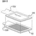
図1〜図3に示すように、表示装置100は2つの表示モジュール10,20を積層して成る2層式表示装置である。下側の表示モジュール10は、画像表示に適しているので画像表示モジュールと呼び、上側の表示モジュール20は文字表示に適しているので文字表示モジュールと呼ぶ。
画像表示モジュール10,文字表示モジュール20には、各々フレキシブルプリント基板150,151を介して表示データとともに表示のための制御信号などが伝送される。
The
As shown in FIGS. 1 to 3, the
Control signals for display and the like are transmitted to the
画像表示モジュール10は、例えばSTN液晶を用いたTFT方式の液晶表示モジュールであり、公知のように液晶11を封入した2枚のガラス基板12と、基板12を挟んで配置される2枚の偏光板13と、光源141を含むバックライト部14と、不図示のカラーフィルタなどから成る。ガラス基板12の内側に設けた透明電極(不図示)は、液晶を実質的にマトリクス状に分割し、分割された画素ごとに任意の電圧を印加できるよう配線され、これにより光の透過率を画素ごとに任意に設定できる。
The
バックライト部14からの光は、透過状態にある画素を透過して上方に射出され、これにより表示が視認される。この表示方式は、透過率、換言すれば光の射出量を画素ごとに任意に制御できるため、豊かな階調表現が可能であり、しかもカラーフィルタを用いているので、写真画像や動画のフルカラー表示に適している。
The light from the
一方、文字表示モジュール20は、2枚のガラス基板22にコレステリック液晶21を封入して成る。不図示の透明電極は、マトリクス状に分割された画素ごとに電圧を印加できるよう配線され、これにより各画素は透過状態と反射状態とに切換可能とされる。この表示モジュール20は外光を利用して表示を行うもので、反射領域に導かれた外光は拡散反射される。コレステリック液晶の場合、特定波長の光が反射されるので、その反射光を例えば緑色、赤色、青色、黄色となるように構成することができる。以下では、反射光を黄色とした例について説明するが、その他の色であっても構わない。また透過領域に導かれた光は液晶層21を透過して下方に導かれるので、下部に黒色板等の吸収層を配置することで黒っぽく見せることができる。
On the other hand, the
したがって、文字表示モジュール20において、例えば表示したい文字部分を透過状態とし、その周囲を反射状態とすれば黄色地に黒い文字を表示させることができる。逆に文字部分を反射状態とし、その周囲を透過状態とすれば、黒地に黄色い文字を表示させることができる。この表示方式は、一般にモノクロ表示に限定され、また多くの階調表現は望めないので、写真画像や動画には向かない。しかし、背景技術でも述べたように、コレステリック液晶はメモリ性を有しているので、電源を切っても表示状態を維持でき、大幅な省電力に寄与する。
Therefore, in the
文字表示モジュール20は、下側のガラス基板22が画像表示モジュール10の上側の偏光板13に略密着するように重ね合わされ、各々のモジュール10,20の表示画面が完全に重なって1つの画面100aを構成する。
The
図4は表示制御に関する制御ブロック図を示し、主要な構成のみ図示してある。撮像装置37は、撮像素子、A/D変換回路、画像信号処理回路、記録回路などから構成され、撮像素子の光電変換出力に基づいて画像データを生成し、これをメモリカードMCに記録する。駆動回路32は、上述した画像表示モジュール10を駆動制御するもので、透明電極を介して液晶を駆動する液晶駆動回路32aと、バックライト部14を制御するバックライト制御部32bとから成る。液晶駆動回路33は、文字表示モジュール20を駆動制御する。また装置全体の制御を司る制御手段(回路)であるCPU31には、電源スイッチ91やレリーズスイッチなどを含む操作部34および時計35も接続される。CPU31や各回路はバッテリBTから給電を受ける。
FIG. 4 is a control block diagram related to display control, and only the main configuration is shown. The
次に、表示装置100による表示原理について説明する。
<基本的な表示>
表示装置100で画像を表示するには、図5に示すように画像表示モジュール10で目的とする画像を表示し、バックライト部14をオン(点灯状態)とする一方、文字表示モジュール20の全画素を透過(透明)状態とする。これにより画像表示モジュール10から発した表示光は、透過状態にある文字表示モジュール20を透過して視認される。したがって、画像表示モジュール10を単体で用いたときと同等の表示が実現される。ここで、文字表示モジュール20の全画素を透過状態とした後は、文字表示モジュール20への通電を断ってもその状態が維持されるので、継続して電力消費を伴うのは画像表示モジュール10のみである。
Next, the display principle by the
<Basic display>
In order to display an image on the
一方、文字表示を行う場合には、図6に示すように文字表示モジュール20で表示したい文字部分を透過状態、その周囲を反射状態とするとともに、画像表示モジュール10は、液晶部およびバックライト部ともに非通電(オフ)とする。非通電により画像表示モジュール10の全画素は非射出状態(黒色化)するため、文字表示モジュール20の透過部分(文字部)を透過した光がその黒色化部分で吸収され、その部分を黒く表示することができる。つまりオフ状態の画像表示モジュール10は、文字表示モジュール20に必要な吸収層としての役割を果たすことになり、上述した黒色板等を別途設ける必要はない。また、文字表示モジュール20の反射部分(文字の背景部分)は、拡散反射による黄色表示となるから、黄色地に黒文字が表示される。
On the other hand, when performing character display, as shown in FIG. 6, the character portion desired to be displayed by the
上記の文字表示において、文字表示モジュール20での表示後は通電を切っても表示が継続し、また画像表示モジュール10はもともとオフ状態であるから、電力消費量は極めて少なくて済む。因みに、同様の文字表示を画像表示モジュール10にて行うことも可能であるが、この場合は表示の維持に電力を必要とするため、不経済である。
In the above character display, the display is continued even after the power is turned off after the display on the
<混在表示>
次に、画面100aの一部に画像を、他の部分に文字を同時に表示することを考える。例えば、画面上半分に表示された画像に関する情報を下半分に文字表示するようなケースである。この場合は、図7に示すように、画像表示モジュール10の上半分に画像を表示し、下半分は黒表示状態とする。一方、文字表示モジュール20においては、上半分を透過状態とし、下半分は文字部分を透過状態、それ以外を反射状態とする。このようにすることで、画面上半分では画像表示モジュール10による画像が文字表示モジュール20の透過部分を通して視認でき、下半分では文字表示モジュール20による文字表示(黄色地に黒文字)が視認できる。また、画像表示モジュールとして有機ELなどの自己発光素子を用いた場合は、画像表示モジュール10の下半分はオフでよいため、画像表示モジュール単体で同様の表示を行った場合と比べで消費電力は半分で済む。なお、画像表示領域と文字表示領域の数や位置、大きさを任意に変更できることはいうまでもない。
<Mixed display>
Next, consider that an image is displayed on a part of the
<文字のカラー表示>
文字表示モジュール単体では文字のカラー表示はできないが、画像表示モジュール10との組み合わせによりカラー表示が可能となる。例えば文字を赤色で表示したい場合、図8に示すように文字表示モジュール20の文字部分を透過状態、他の部分を反射状態とする。画像表示モジュール10においては、上記文字部分に相当する箇所、あるいは文字相当箇所を含む所定領域を赤色とするとともに、他は黒色表示とし、バックライトはオンとする。このようにすることで、文字表示モジュール10の透過部分(文字部分)を通して画像表示モジュール10の赤が視認できるので、黄色地に赤の文字が表示されることになる。赤に限らず任意の色の文字を表示でき、表示項目ごと、あるいは文字ごとに色を変えることも容易である。
<Character color display>
Although the character display module alone cannot display characters in color, color display is possible by combining with the
上記の表示原理をデジタルカメラに適用した場合の表示例を説明する。
デジタルカメラは、電源スイッチ91のオン操作に伴って電源オン状態に、オフ操作で電源オフ状態になる。電源オフ状態では、時計35による時計機能を実現するための計時回路やCPU31など一部を除く殆どの回路への給電が断たれ、もちろん撮影は禁止される。またカメラはオートパワーオフ機能を備え、電源オン状態で何らの操作もなされない状態が一定時間継続すると、電力の消耗を抑えるために自動的に電源オフ状態となる。オートパワーオフ状態で何らかの操作(例えば、半押し操作)を行うと、電源オン状態に復帰する。
A display example when the above display principle is applied to a digital camera will be described.
The digital camera is turned on when the
オートパワーオフについてより詳しく説明すると、CPU31、時計35、操作部34、操作検出回路310、スイッチ制御回路312には、電源スイッチ91の操作状態に拘わらず、バッテリBTより常に電力が供給されている。この状態は、電源スイッチ91による電源のオフ操作がなされた際の電源オフ状態と同じ状態である。電源オン状態においては、CPU31、時計35、操作部34、操作検出回路310、スイッチ制御回路312に加えて、スイッチ313を介してその他の回路にも電力が供給されている。電源オン状態において、時計35は操作部34によって何らの操作も継続してなされない時間を計測し、計測した時間が予め定められた所定時間以上となると、CPU31のスイッチ制御回路312によって、スイッチ313を開状態として、上記その他の回路への電力の供給を遮断する。なお、その他の回路への電源供給を継続しつつ、その他の回路の動作状態を制御する制御入力端子を介してその他の回路の動作をスタンバイ状態(スリープ状態)とするものであってもよい。このような制御を行うことによっても消費電力を低減することができる。
The auto power off will be described in more detail. Electric power is always supplied from the battery BT to the
オートパワーオフ状態で操作検出回路310は、操作部34の操作部材が操作がなされたことを検出すると、スイッチ制御回路312によってスイッチ313を閉状態とし、その他の回路へ電源を供給する。電源の供給に代えて、上述の制御入力端子への電源入力によってその他の回路の動作をスタンバイ状態(スリープ状態)からアクティブ状態にするものであってもよい。
When the
<電源オン時>
カメラは電源オンに伴って撮像を開始し、繰り返し撮像される画像を表示装置100に逐次更新表示する(スルー画表示)。これにより表示装置100をファインダ代わりに使用することができる。レリーズ操作がなされると、メモリカードMCへの記録を目的とした撮像を行い、撮像された画像を所定時間だけ表示装置100に表示する(フリーズ画表示)。さらに、操作によって再生モードを設定することで、メモリカードMCに記録された画像を読み出して表示装置100に表示することも可能である(再生画表示)。この再生画表示では、1画像表示の他に、1画面に複数画像をサムネイル表示することができる。そして、これらスルー画表示,フリーズ画表示および再生画表示は、いずれも図5で説明した表示形態でなされる。
<When power is on>
The camera starts imaging when the power is turned on, and sequentially updates and displays images repeatedly captured on the display device 100 (through image display). Thereby, the
また、画像と画像情報(撮影日付や撮影データなど)とを同時に表示する場合には、図7で説明した表示形態を用いることができる。さらに、画像以外にカスタム設定などのメニュー表示も可能であり、表示を見ながら種々の設定を行うことができる。メニュー表示では、視認性を良好にする上でカラー表示が適しているため、通常は図5に示す表示形態で行われる。ただし、バッテリ残量が少ないときなどには、図6,図7に示す方式で行ってもよい。例えばバッテリチェック機能を利用し、バッテリ残量が所定値を下回ると、図5の表示形態から図6または図7の表示形態に自動的に切換わるようにすると便利である。ユーザの操作によって表示形態を切換えられるようにしてもよい。 In the case where an image and image information (such as shooting date and shooting data) are displayed at the same time, the display mode described with reference to FIG. 7 can be used. Further, in addition to images, menu display such as custom settings is also possible, and various settings can be made while viewing the display. In the menu display, color display is suitable for improving the visibility, and therefore, it is usually performed in the display form shown in FIG. However, when the remaining battery level is low, the method shown in FIGS. 6 and 7 may be used. For example, it is convenient to automatically switch from the display form of FIG. 5 to the display form of FIG. 6 or 7 when the battery check function is used and the remaining battery level falls below a predetermined value. The display form may be switched by a user operation.
<電源オフ時>
従来カメラは、電源オフ状態(オートパワーオフ状態も含む)では、電力の消耗を抑えるために表示装置への給電を断ち、何も表示しないのが普通である。しかし、本実施形態のカメラでは、文字表示モジュール20を用いることで、表示の更新時以外は電力消費を伴わずに表示の継続が可能なため、電源オフ状態でも文字表示モジュール20による表示を行う。すなわちCPU31は、電源スイッチ91のオフ操作、あるいはオートパワーオフ待ち時間の満了に伴い、自動的に図6の表示形態に切換え、予め設定された表示コンテンツを表示し、しかる後に電源をオフする。これによれば、従来は電源をオンしないと確認できなかった情報が電源オフのままでも確認でき、カメラの使い勝手が向上する。
電源オフ状態からオン状態に復帰すると、上述した電源オン時の表示形態に自動的に切換わる。
<When power is off>
Conventional cameras normally do not display anything in the power-off state (including the auto power-off state) by cutting off the power supply to the display device to suppress power consumption. However, in the camera of the present embodiment, by using the
When returning from the power-off state to the on-state, the display mode is automatically switched to the above-described display state at the time of power-on.
次に、電源オフ時における表示例を図9〜図15に示す。
図9は電源オフ時に現在の日付および時刻を文字表示モジュール20により表示する例を示している。電源オフ時でも時計35は作動しているので、時計35からの情報に基づいて時刻表示が行える。図のような時分表示の場合、1分に1回表示の更新を行うため表示の更新時に文字表示モジュール20への電力の供給が必要となるが、その更新時以外は電力を消耗しないので、表示にかかる電力は極めて少なくて済む。また本例では、画面の下に電源オフ状態である旨が文字表示される。ユーザは、画面に日付などの表示がなされていることで電源オンと勘違いしがちであるが、電源オフの旨を表示しておくことで勘違いのおそれはなくなる。例えば、「撮影するには電源をオンしてください」のような表示でもよい。
Next, display examples when the power is turned off are shown in FIGS.
FIG. 9 shows an example in which the current date and time are displayed by the
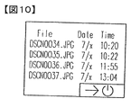
図10は電源オフ時に撮影履歴を文字表示モジュール20により表示する例を示している。ここでは履歴情報として、撮影によって生成され記録された画像ファイルのファイル名と、撮影日付と、撮影時刻とを表形式で表示する。複数の画像ファイルのうち最新の幾つかが表示される。新しいファイルほど上になるような表示でもよい。次に撮影を行うまで履歴情報が変化することはないため、電源オフ時の表示にかかる消費電力は実質ゼロである。なお、画面右下の絵文字は、電源のオンを促す(現在は電源オフ状態であることを示す)ものである。
FIG. 10 shows an example in which the shooting history is displayed by the
図11は電源オフ時に設定されている撮影条件およびバッテリ残量を文字表示モジュール20により表示する例を示している。ここでは撮影条件として、現在の画質モード、撮影モード、スピードライト情報、測光モード、撮影可能駒数などを文字あるいは絵柄で表示する。これ以外にも、設定絞り値や設定シャッタ秒時などを表示してもよい。これらの情報も電源オフ時に変化することはないので、電源オフ時の表示にかかる消費電力は実質ゼロである。なお、撮影可能駒数に関しては、メモリカードの入れ替えにより変化する可能性があるので、入れ替え時に表示を更新してもよい。
FIG. 11 shows an example in which the
図12は電源オフ時にカメラの各種メニューを文字表示モジュール20により表示する例を示している。メニューには、画像再生に関する再生メニュー、画像編集に関する画像編集メニュー、Helpメニューなどがある。予めユーザによって選択されたいずれかのメニューを表示してもよいし、図示のように複数の項目を表示し、その中からユーザが選択できるようにしてもよい。またユーザが予め入力したスケジュール情報やメモ書き等を表示できるようにしてもよい。これらの表示では、表示内容を変更したりスクロールさせるとき以外は電力を必要としない。
FIG. 12 shows an example in which various menus of the camera are displayed by the
図13,図14は電源オフ時に既に撮影した画像を文字表示モジュール20により表示する例であり、図13は1画像表示を、図14は4画像のサムネイル表示を行う例をそれぞれ示している。いずれの場合も最近の撮影画像を表示することで、電源をオンすることなく前回の撮影内容や撮影場所等が分かり、便利である。なお、上述したように文字表示モジュール20はモノクロ表示であり、かつ階調表現に乏しいため画像表示には向かないが、何が写っているかさえ確認できればよいので、特に問題はない。
FIGS. 13 and 14 are examples in which images already taken when the power is turned off are displayed by the
上述した幾つかの表示内容を組み合わせて表示してもよい。例えば図15は画面を3領域に分割し、それぞれに最近の画像およびその撮影年月日時分、撮影履歴、カメラの設定情報を表示する例を示している。その他の組み合わせでもよい。 You may display combining some display contents mentioned above. For example, FIG. 15 shows an example in which the screen is divided into three areas, each displaying the latest image, its shooting date, shooting history, and camera setting information. Other combinations may be used.
上記以外にも、例えばカメラに電子ブックとしての機能(電子ブック閲覧モード)を持たせることも可能である。操作部34の操作によって電子ブック閲覧モードに設定された場合は、メモリカードMCを利用して電子ブックのコンテンツを導入するようにすればよい。電子ブックとしての利用は電源のオン・オフに拘わらず使用できるようにしてもよいが、電源オフに限定すれば、例えばズームアップ/ダウンボタンをページ送り/戻しボタンとして使用することもできる。
In addition to the above, for example, the camera can have a function as an electronic book (electronic book browsing mode). When the electronic book browsing mode is set by the operation of the
電子ブック閲覧モードが設定され、電源がオフ状態の場合には、スイッチ制御回路312は、操作部34のズームアップ/ダウンボタンが操作されても、スイッチ313の開状態を保持するように制御する。この状態においてもズームアップ/ダウンボタンが操作されて、文字表示モジュール20による表示を更新するときのみ、文字表示モジュール20に電力が供給される。なお、電子ブック閲覧モードが設定され、電子ブックコンテンツの表示が指示されると、電源スイッチ91の状態に拘わらず、文字表示モジュール20による表示に自動的に切換えるように構成してもよい。このように構成することによっても装置の電力消費を低減することができる。
When the electronic book viewing mode is set and the power is off, the
カメラは図9〜図15の表示機能を全て備え、予めユーザがいずれを表示するかを設定できるようにすることが望ましい。いずれの表示が選択された場合でも、表示スペースに余裕があれば、図9,図10に示したように電源オフの旨を明示することが望ましい。なお、少なくともいずれか1つの表示機能のみを持つものでもよい。
なお、上記実施形態においては、電源オフ状態として、計時回路やCPU31など一部を除く回路への給電を遮断する例について説明したが、装置内の全ての回路への給電を遮断する構成としても、コレステリック液晶などを用いた記憶型表示素子を用いることで、電源オフ時にも表示を継続できる。
It is desirable that the camera has all of the display functions of FIGS. 9 to 15 so that the user can set which of them is displayed in advance. Regardless of which display is selected, it is desirable to clearly indicate that the power is off as shown in FIGS. Note that at least one of the display functions may be provided.
In the above-described embodiment, the example in which the power supply to the power-off state is cut off from the power supply to circuits except for a part such as the timing circuit and the
−第2の実施形態−
次に、本発明を携帯電話機に適用した場合の第2の実施形態を説明する。
図19に示す携帯電話機は、メインの表示装置100Aに加えて背面にも表示装置100Bを有し、その双方が図1〜図3で説明した2層式の表示装置とされる。なお、いずれか一方が2層式でもよい。
-Second Embodiment-
Next, a second embodiment when the present invention is applied to a mobile phone will be described.
The mobile phone shown in FIG. 19 has a
図20は上記携帯電話機の制御系を示すブロック図である。携帯電話機の動作全体を司る制御手段(回路)であるCPU101には、上記表示装置100A,100Bと、メモリ102と、外部インターフェイス(I/F)108と、バッテリ109と、通信制御部110と、時計111と、操作部112とが接続されている。
FIG. 20 is a block diagram showing a control system of the mobile phone. The
操作部材112は、電話機のダイヤルボタンなどを含み、押下されたボタンに対応する操作信号をCPU101へ送出する。通信制御部110は、アンテナ110Aおよび無線送受信回路を含み、CPU101の指令により不図示の基地局を介して他の電話機との間で音声通信を行う。電話音声以外にも、カメラ機能を用いて撮影された画像データなどが送受信可能である。105は着脱可能なメモリカードであり、CPU101は、メモリカード105に画像データ等を記録したり、読み出すことが可能である。外部インターフェイス108は、CPU101の指令により不図示のケーブルまたはクレードルを介して外部機器との間でデータを送受信する。
The
CPU101、時計111、操作部112、操作検出回路101A、スイッチ制御回路101Bには、バッテリ109より常に電力が供給されている。待ち受け時以外は、CPU101、時計111、操作部112、操作検出回路101A、スイッチ制御回路101Bに加えて、スイッチ120を介してその他の回路にも電力が供給されている。この状態で、時計111は操作部112によって何らの操作も継続してなされない時間を計測し、計測した時間が予め定められた所定時間以上となると、CPU101のスイッチ制御回路101Bによって、スイッチ120を開状態として、上記その他の回路への電力の供給を遮断する。
Power is always supplied from the
通常使用時には、画像表示モジュール10を用い、図5の表示形態で種々の表示を行う。表示コンテンツとしては、基本的な電話操作画面や設定画面の他に、オンラインサービスモードを備えたものでは、Webコンテンツ(ホームページ、画像、動画)やメール操作画面、また撮影機能を備えたものでは、撮影した静止画像、動画像、さらには通信相手先の携帯電話機から送信された静止画像、動画像や文字データなどがある。画像表示モジュール10を用いることで、フルカラー表示が可能であり、また画面の切換えやスクロールを高速で行うことができる。
During normal use, the
上述したように、何らの操作もなされない状態が所定時間継続すると、携帯電話機はCPU101の制御によって自動的に待ち受け状態となるが、表示制御手段であるCPU101は、この待ち受け状態への移行に伴って図6の表示形態に切換え、予め設定された表示コンテンツを文字表示モジュール20にて表示する。上述したように、図6の表示形態によれば最小限の電力消費で済む。待ち受け状態で何らかの操作がなされると、自動的に図5の表示形態に戻る。
As described above, when a state in which no operation is performed continues for a predetermined time, the mobile phone automatically enters a standby state under the control of the
図19(a)は、待ち受け時の表示コンテンツとして、日付および時刻表示に加えて、予め入力したスケジュールを表示する例を示している。スケジュール表示は、時刻の経過とともに表示を更新する(繰り上げる)必要があるが、これは例えば1時間あるいは30分に1回程度としてもよい。待ち受け状態においては、時計111には常時電力を供給して計時動作を行い、文字表示モジュール20には、30分あるいは1時間毎に1回程度の表示変更時にのみ電力を供給する。
FIG. 19A shows an example in which a schedule input in advance is displayed in addition to the date and time display as the display content at the time of standby. The schedule display needs to be updated (raised) as time elapses, but this may be, for example, about once every hour or 30 minutes. In the standby state, power is constantly supplied to the
図19(c)は待ち受け時に背面の表示装置100Bに日付およびその日のニュースを表示する例を示している。これは、オンラインサービスモードを用いてニュースサイトにアクセスし、最新情報をダウンロードして表示することで達成できる。ダウンロードおよび表示の更新が数時間おきに自動で行われるようにすることで、待ち受け状態のまま常に最新のニュースを確認できる。更新間隔をユーザが設定できるようにしてもよい。
FIG. 19C shows an example in which the date and the news of the day are displayed on the
待ち受け状態においては、オンラインサービス情報をダウンロードするために、通信制御部110に数時間おきに電力が供給されるようにし、これに同期してダウンロードした情報内容を表示装置100Bの文字表示モジュール20に更新表示させるための電力を供給する。また、オンラインサービスモード時には、特定の操作部材の操作によっても待ち受け状態を維持する構成とすれば、特定の操作部材の操作によってユーザが所望するときに最新情報のダウンロードおよび文字表示モジュール20の表示の更新を低消費電力で実現できる。なお、オンラインサービスモードが設定され、オンラインサービスコンテンツの表示が指示されると、待ち受け状態であるか否かに拘わらず、文字表示モジュール20による表示に自動的に切換えるように構成してもよい。このように構成することによっても装置の電力消費を低減することができる。
In the standby state, in order to download online service information, power is supplied to the
ところで、文字表示モジュール20は外光を利用して表示を行う性質上、周囲が暗いと表示が見づらく、暗闇では表示が確認できない。そこで、周囲が暗いと考えられる時間帯は、文字表示モジュール20による表示は不可とし、あらゆる表示を画像表示モジュール10で(図5の表示形態で)行えるようにしてもよい。かかる時間帯はユーザの生活様式で異なるため、ユーザが時間帯を予め設定できるようにすることが望ましい。例えば、「深夜0:00〜5:00」のように入力すると、その時間帯は文字表示モジュール20による表示が不可となり、画像表示モジュール10で表示がなされるようにすればよい。逆に周囲が明るいと想定される時間帯(例えば、7:00〜17:00)は、表示モジュール20での表示をデフォルトの設定としてもよい。
By the way, because the
次に、表示装置の変形例を示す。
図21に示す表示装置は、画像表示モジュールとして、前述の液晶モジュールに代えて有機ELモジュール50を用いたものである。有機ELモジュール50は、公知のように駆動基板51と、基板51上にマトリクス状にパターン配列された複数の有機EL素子から成る発光層52と、発光層52を覆うガラス板53と、不図示のカラーフィルタなどから構成される。表示データ等は、例えばフレキシブルプリント基板152によって伝送される。素子自体が発光するためバックライトは不要であり、液晶モジュールと比べて薄型化が図れる。この場合も素子ごとに発光量を制御することで光の射出量を画素ごとに制御でき、またカラーフィルタが設けられているため、液晶モジュールと同様に画像や動画のフルカラー表示に適している。また画素を非発光とすれば黒色化するため、文字表示モジュール20の透過領域を透過した光を吸収し、その領域を黒く見せることができる。したがって、先の実施形態と同様の使い方が可能である。なお、無機EL素子を用いたものでもよい。
Next, a modification of the display device is shown.
The display device shown in FIG. 21 uses an
図22は、1枚のガラス基板を画像表示モジュールと文字表示モジュールとで兼用した例を示している。すなわち、図のガラス基板61は、画像表示モジュール(液晶モジュール)の上側のガラス基板と、文字表示モジュールの下側のガラス基板とを兼用している。ガラス基板61の下面側には画像表示モジュール用の透明電極部が、上面側には文字表示モジュール用の透明電極部がそれぞれ形成される。この場合、画像表示モジュールの上側の偏光板13は、文字表示モジュールの上面に配置される。さらに図23は、画像表示モジュール(有機ELモジュール)の上側のガラス基板と、文字表示モジュールの下側のガラス基板とを1枚のガラス基板62で兼用した例を示している。
このようにガラス基板を2つの表示モジュールで兼用することで、上述と同様の作用効果を奏しつつ、ガラス基板が1枚少なくて済み、部品点数の低減および薄型化が図れる。
FIG. 22 shows an example in which one glass substrate is used as both an image display module and a character display module. That is, the
In this way, by sharing the glass substrate with the two display modules, it is possible to reduce the number of components and reduce the thickness of the glass substrate while reducing the number of the glass substrate while achieving the same operational effects as described above.
なお、文字表示モジュールの表示素子としてコレステリック液晶を用いた例を示したが、PN(ポリマーネットワーク)液晶を用いてもよい。PN液晶も画素ごとに透過状態/反射状態を設定して表示を行うものであるから、上述と同様の使い方ができる。ただし、メモリ性がないため表示の維持には通電し続ける必要があるが、発光を伴わないため消費電力はごく少なくて済み、画像表示モジュールで全ての表示を賄う場合と比べて省電力に寄与する。 In addition, although the example which used the cholesteric liquid crystal as a display element of a character display module was shown, you may use a PN (polymer network) liquid crystal. Since the PN liquid crystal also performs display by setting the transmission state / reflection state for each pixel, it can be used in the same manner as described above. However, since there is no memory, it is necessary to keep energizing to maintain the display, but since it does not emit light, it consumes very little power and contributes to power saving compared to the case where all display is provided by the image display module. To do.
また、PN液晶の場合は、前述の反射光が白色光となるため、白黒の表示が可能である。つまりコレステリック液晶で説明した黄色表示を白色表示(白文字や白地)とすることができ、より高コントラストを実現できる。 In the case of a PN liquid crystal, the reflected light is white light, so that monochrome display is possible. That is, the yellow display described in the cholesteric liquid crystal can be changed to a white display (white character or white background), and higher contrast can be realized.
以上では、電子機器としてデジタルカメラおよび携帯電話機を示したが、それ以外の電子機器、例えばPDAや電子ブックを含む各種ポータブル機器、あるいはモバイル式のパーソナルコンピュータなどにも本発明を適用できる。 In the above, a digital camera and a mobile phone are shown as electronic devices. However, the present invention can be applied to other electronic devices such as various portable devices including PDAs and electronic books, or mobile personal computers.
10 画像表示モジュール(液晶モジュール)
11 液晶層
12 ガラス基板
13 偏光板
14 バックライト部
20 文字表示モジュール
21 液晶層
22 ガラス基板
31 CPU
32 駆動回路
32a,33 液晶駆動回路
32b バックライト制御部
34 操作部
35 時計
37 撮像装置
50 画像表示モジュール(有機ELモジュール)
51 基板51
52 発光層
53 ガラス板
61,62 ガラス基板
91 電源スイッチ
92 レリーズボタン
94 撮影レンズ
100,100A,100B 表示装置
100a 表示画面
141 光源
150,151,152 フレキシブルプリント基板
BT バッテリ
10 Image display module (liquid crystal module)
DESCRIPTION OF
32
51
52
Claims (17)
電源オン時には少なくとも前記第1の表示形態での表示を許可し、電源オフ時には、前記第1の表示形態での表示を不可として前記第2の表示形態での表示を許可する表示制御手段とを具備することを特徴とする表示装置付き電子機器。 A first display mode for performing light emission display by controlling the light emission amount for each pixel, and a second display mode for performing display by setting a transmissive state for transmitting external light and a reflective state for reflecting for each pixel. A display device capable of
Display control means for permitting at least display in the first display mode when the power is turned on and disabling display in the first display mode and permitting display in the second display mode when the power is turned off. An electronic device with a display device, comprising:
前記第1の表示形態での表示時に、何らの操作もなされない状態が所定時間継続すると、前記第2の表示形態に切換えて表示を行う表示制御手段とを具備することを特徴とする表示装置付き電子機器。 A first display mode for performing light emission display by controlling the light emission amount for each pixel, and a second display mode for performing display by setting a transmissive state for transmitting external light and a reflective state for reflecting for each pixel. A display device capable of
A display device comprising: display control means for switching to the second display mode and displaying when a state in which no operation is performed for a predetermined time during display in the first display mode. With electronic equipment.
前記第2の表示形態での表示時に何らかの操作が行われると、前記第1の表示形態に切換えて表示を行う表示制御手段とを具備することを特徴とする表示装置付き電子機器。 A first display mode for performing light emission display by controlling the light emission amount for each pixel, and a second display mode for performing display by setting a transmissive state for transmitting external light and a reflective state for reflecting for each pixel. A display device capable of
An electronic apparatus with a display device, comprising: display control means for switching to the first display form and performing a display when any operation is performed during display in the second display form.
動作モードを設定する設定手段と、
前記設定手段によって設定された動作モードに応じて、前記表示装置による表示形態を前記第1の表示形態と前記第2の表示形態とで切換える表示制御手段とを具備することを特徴とする表示装置付き電子機器。 A first display mode for performing light emission display by controlling the light emission amount for each pixel, and a second display mode for performing display by setting a transmissive state for transmitting external light and a reflective state for reflecting for each pixel. A display device capable of
Setting means for setting the operation mode;
A display device comprising: display control means for switching a display form by the display device between the first display form and the second display form in accordance with an operation mode set by the setting means. With electronic equipment.
前記表示装置に表示する表示コンテンツに応じて、前記表示装置による表示形態を前記第1の表示形態と前記第2の表示形態とで切換える表示制御手段とを具備することを特徴とする表示装置付き電子機器。 A first display mode for performing light emission display by controlling the light emission amount for each pixel, and a second display mode for performing display by setting a transmissive state for transmitting external light and a reflective state for reflecting for each pixel. A display device capable of
With a display device, comprising display control means for switching a display form by the display device between the first display form and the second display form in accordance with display contents displayed on the display device Electronics.
予め設定された時間帯では前記第2の表示形態による表示を不可として前記第1の表示形態による表示を許可し、それ以外の時間帯では前記第1の表示形態または前記第2の表示形態での表示を許可する表示制御手段とを具備することを特徴とする表示装置付き電子機器。 A first display mode for performing light emission display by controlling the light emission amount for each pixel, and a second display mode for performing display by setting a transmissive state for transmitting external light and a reflective state for reflecting for each pixel. A display device capable of
In the preset time zone, display in the second display mode is disabled and display in the first display mode is permitted, and in other time zones, the first display mode or the second display mode is used. Display control means for permitting the display of the electronic apparatus with a display device.
Priority Applications (4)
| Application Number | Priority Date | Filing Date | Title |
|---|---|---|---|
| JP2005017882A JP2006208536A (en) | 2005-01-26 | 2005-01-26 | Electronic equipment with display apparatus |
| US11/666,623 US8106852B2 (en) | 2004-11-04 | 2005-10-28 | Display device and electronic device |
| EP05805366A EP1826739A4 (en) | 2004-11-04 | 2005-10-28 | Display device and electronic device |
| PCT/JP2005/019922 WO2006049105A1 (en) | 2004-11-04 | 2005-10-28 | Display device and electronic device |
Applications Claiming Priority (1)
| Application Number | Priority Date | Filing Date | Title |
|---|---|---|---|
| JP2005017882A JP2006208536A (en) | 2005-01-26 | 2005-01-26 | Electronic equipment with display apparatus |
Publications (1)
| Publication Number | Publication Date |
|---|---|
| JP2006208536A true JP2006208536A (en) | 2006-08-10 |
Family
ID=36965498
Family Applications (1)
| Application Number | Title | Priority Date | Filing Date |
|---|---|---|---|
| JP2005017882A Pending JP2006208536A (en) | 2004-11-04 | 2005-01-26 | Electronic equipment with display apparatus |
Country Status (1)
| Country | Link |
|---|---|
| JP (1) | JP2006208536A (en) |
Cited By (11)
| Publication number | Priority date | Publication date | Assignee | Title |
|---|---|---|---|---|
| JP2008149602A (en) * | 2006-12-19 | 2008-07-03 | Brother Ind Ltd | Electronic apparatus, method for controlling displaying on display section provided thereto, and method for displaying |
| US8139240B2 (en) | 2008-03-07 | 2012-03-20 | Sharp Kabushiki Kaisha | Image forming apparatus |
| JP2013502616A (en) * | 2009-08-20 | 2013-01-24 | アマゾン テクノロジーズ インコーポレイテッド | Fused display including heterogeneous display devices |
| WO2014024766A1 (en) * | 2012-08-10 | 2014-02-13 | シャープ株式会社 | Display apparatus |
| CN105492221A (en) * | 2013-09-24 | 2016-04-13 | Hoya株式会社 | Cover glass for electronic apparatus, and production method therefor |
| JP2016059751A (en) * | 2014-09-22 | 2016-04-25 | カシオ計算機株式会社 | Display device, electronic tool, and control method and control program thereof |
| JP2017146614A (en) * | 2017-04-28 | 2017-08-24 | カシオ計算機株式会社 | Display device, electronic tool, and control method and control program thereof |
| JP2017173085A (en) * | 2016-03-23 | 2017-09-28 | カシオ計算機株式会社 | Electronic apparatus and time display control method |
| CN108292491A (en) * | 2015-12-22 | 2018-07-17 | 卡西欧计算机株式会社 | Display device and its control method |
| JP2018170612A (en) * | 2017-03-29 | 2018-11-01 | 京セラ株式会社 | Portable electronic apparatus, control method, and control program |
| JP2018170605A (en) * | 2017-03-29 | 2018-11-01 | 京セラ株式会社 | Portable electronic apparatus, control method, and control program |
Citations (5)
| Publication number | Priority date | Publication date | Assignee | Title |
|---|---|---|---|---|
| JP2000347184A (en) * | 1999-06-09 | 2000-12-15 | Minolta Co Ltd | Information display device |
| JP2004069926A (en) * | 2002-08-05 | 2004-03-04 | Seiko Epson Corp | Display device with mirror function, and electronic device |
| JP2004245976A (en) * | 2003-02-12 | 2004-09-02 | Optrex Corp | Display device |
| JP2004302321A (en) * | 2003-03-31 | 2004-10-28 | Seiko Epson Corp | Display apparatus, electronic equipment and display method |
| JP2004341156A (en) * | 2003-05-15 | 2004-12-02 | Seiko Instruments Inc | Display device |
-
2005
- 2005-01-26 JP JP2005017882A patent/JP2006208536A/en active Pending
Patent Citations (5)
| Publication number | Priority date | Publication date | Assignee | Title |
|---|---|---|---|---|
| JP2000347184A (en) * | 1999-06-09 | 2000-12-15 | Minolta Co Ltd | Information display device |
| JP2004069926A (en) * | 2002-08-05 | 2004-03-04 | Seiko Epson Corp | Display device with mirror function, and electronic device |
| JP2004245976A (en) * | 2003-02-12 | 2004-09-02 | Optrex Corp | Display device |
| JP2004302321A (en) * | 2003-03-31 | 2004-10-28 | Seiko Epson Corp | Display apparatus, electronic equipment and display method |
| JP2004341156A (en) * | 2003-05-15 | 2004-12-02 | Seiko Instruments Inc | Display device |
Cited By (18)
| Publication number | Priority date | Publication date | Assignee | Title |
|---|---|---|---|---|
| US8125658B2 (en) | 2006-12-19 | 2012-02-28 | Brother Kogyo Kabushiki Kaisha | Electronic device including non-volatile display portion |
| JP2008149602A (en) * | 2006-12-19 | 2008-07-03 | Brother Ind Ltd | Electronic apparatus, method for controlling displaying on display section provided thereto, and method for displaying |
| US8139240B2 (en) | 2008-03-07 | 2012-03-20 | Sharp Kabushiki Kaisha | Image forming apparatus |
| JP2013502616A (en) * | 2009-08-20 | 2013-01-24 | アマゾン テクノロジーズ インコーポレイテッド | Fused display including heterogeneous display devices |
| WO2014024766A1 (en) * | 2012-08-10 | 2014-02-13 | シャープ株式会社 | Display apparatus |
| JPWO2015046220A1 (en) * | 2013-09-24 | 2017-03-09 | Hoya株式会社 | Cover glass for electronic equipment and manufacturing method thereof |
| CN105492221A (en) * | 2013-09-24 | 2016-04-13 | Hoya株式会社 | Cover glass for electronic apparatus, and production method therefor |
| JP2016059751A (en) * | 2014-09-22 | 2016-04-25 | カシオ計算機株式会社 | Display device, electronic tool, and control method and control program thereof |
| US11194383B2 (en) | 2015-12-22 | 2021-12-07 | Casio Computer Co., Ltd. | Display device and method for controlling same |
| CN108292491A (en) * | 2015-12-22 | 2018-07-17 | 卡西欧计算机株式会社 | Display device and its control method |
| CN108292491B (en) * | 2015-12-22 | 2021-08-31 | 卡西欧计算机株式会社 | Display device and control method thereof |
| US11079835B2 (en) | 2015-12-22 | 2021-08-03 | Casio Computer Co., Ltd. | Display device and method for controlling same |
| EP3396662A4 (en) * | 2015-12-22 | 2019-06-19 | Casio Computer Co., Ltd. | Display device and method for controlling same |
| US20200004319A1 (en) * | 2015-12-22 | 2020-01-02 | Casio Computer Co., Ltd. | Display device and method for controlling same |
| JP2017173085A (en) * | 2016-03-23 | 2017-09-28 | カシオ計算機株式会社 | Electronic apparatus and time display control method |
| JP2018170605A (en) * | 2017-03-29 | 2018-11-01 | 京セラ株式会社 | Portable electronic apparatus, control method, and control program |
| JP2018170612A (en) * | 2017-03-29 | 2018-11-01 | 京セラ株式会社 | Portable electronic apparatus, control method, and control program |
| JP2017146614A (en) * | 2017-04-28 | 2017-08-24 | カシオ計算機株式会社 | Display device, electronic tool, and control method and control program thereof |
Similar Documents
| Publication | Publication Date | Title |
|---|---|---|
| JP2006208536A (en) | Electronic equipment with display apparatus | |
| WO2006049105A1 (en) | Display device and electronic device | |
| US8345429B2 (en) | Mobile terminal having detachable sub-module | |
| JP4254672B2 (en) | Portable information equipment | |
| JP5114491B2 (en) | Display with variable reflectivity | |
| JP2006243329A (en) | Display apparatus | |
| JP2006133346A (en) | Display apparatus | |
| US9019252B2 (en) | Display device, display method, and program for saving power in a standby mode | |
| US20090207297A1 (en) | Display apparatus and imaging apparatus | |
| WO2006130246A2 (en) | Combination full color and monochrome reflective display | |
| JP2002051143A (en) | Portable information terminal device | |
| JP2006091091A (en) | Portable information apparatus | |
| JP2006191387A (en) | Portable telephone set with camera function | |
| JP2006041832A (en) | Portable radio terminal with switching function of indicator lighting | |
| JP4976770B2 (en) | Display device, display method, program, and storage medium | |
| JP4433959B2 (en) | Portable information equipment | |
| JP2006093802A (en) | Mobile information apparatus | |
| JP2007316239A (en) | Display device | |
| US7230647B1 (en) | Electronic information device having a display and method and apparatus for controlling power-off of the display | |
| JP2006208450A (en) | Method for controlling liquid crystal display apparatus and mobile information apparatus | |
| JP2006178345A (en) | Electrical apparatus | |
| JP2005142916A (en) | Mobile terminal device with camera, its illumination control method and program for illumination control | |
| JP2004333839A (en) | Picture display device and mobile electronic equipment | |
| JP2006279564A (en) | Composite display unit for imaging device, compound display device and display control method | |
| KR100595678B1 (en) | Mobile communication terminal with a display comprised of different types of display |
Legal Events
| Date | Code | Title | Description |
|---|---|---|---|
| A621 | Written request for application examination |
Free format text: JAPANESE INTERMEDIATE CODE: A621 Effective date: 20080111 |
|
| A131 | Notification of reasons for refusal |
Free format text: JAPANESE INTERMEDIATE CODE: A131 Effective date: 20080401 |
|
| A521 | Written amendment |
Free format text: JAPANESE INTERMEDIATE CODE: A523 Effective date: 20080530 |
|
| A131 | Notification of reasons for refusal |
Free format text: JAPANESE INTERMEDIATE CODE: A131 Effective date: 20080715 |
|
| A02 | Decision of refusal |
Free format text: JAPANESE INTERMEDIATE CODE: A02 Effective date: 20081111 |