JP2006201435A - Color filter manufacturing method and color filter - Google Patents
Color filter manufacturing method and color filter Download PDFInfo
- Publication number
- JP2006201435A JP2006201435A JP2005012486A JP2005012486A JP2006201435A JP 2006201435 A JP2006201435 A JP 2006201435A JP 2005012486 A JP2005012486 A JP 2005012486A JP 2005012486 A JP2005012486 A JP 2005012486A JP 2006201435 A JP2006201435 A JP 2006201435A
- Authority
- JP
- Japan
- Prior art keywords
- ink receiving
- color filter
- receiving layer
- support member
- pattern
- Prior art date
- Legal status (The legal status is an assumption and is not a legal conclusion. Google has not performed a legal analysis and makes no representation as to the accuracy of the status listed.)
- Pending
Links
Images
Landscapes
- Optical Filters (AREA)
- Liquid Crystal (AREA)
- Devices For Indicating Variable Information By Combining Individual Elements (AREA)
Abstract
Description
本発明は、電解放射型表示装置、蛍光表示装置、プラズマディスプレイ(PDP)及び液晶表示装置などの表示装置用のカラーフィルタ基板及びカラーフィルタと、その製造方法に関し、特にインクジェット方式を利用した製造方法に用いられるカラーフィルタの製造方法およびカラーフィルタに関する。 The present invention relates to a color filter substrate and a color filter for display devices such as an electrolytic emission display device, a fluorescent display device, a plasma display (PDP), and a liquid crystal display device, and a manufacturing method thereof, and more particularly, a manufacturing method using an inkjet method. The present invention relates to a color filter manufacturing method and a color filter used in the invention.
従来からカラー液晶ディスプレイ等のカラー表示装置に使用されるカラーフィルタは、赤(R)、緑(G)、青(B)の三色をカラーフィルタ構成色とし、これらの三色とブラックマトリクスの黒との着色層を透明基板(例えばガラス基板)上に設けることで構成されている。そして、このカラーフィルタを形成するに際して、着色層を、フォトリソグラフィを用いた染色法や顔料分散法、印刷法によって形成することが提案されている。
また近年は、主としてコストダウンを目的として、インクジェット方式を利用したカラーフィルタの製造方法等も検討されている。
Conventionally, a color filter used in a color display device such as a color liquid crystal display uses three colors of red (R), green (G), and blue (B) as color filter constituent colors, and these three colors and a black matrix. A black colored layer is provided on a transparent substrate (for example, a glass substrate). And when forming this color filter, forming a colored layer by the dyeing | staining method using photolithography, the pigment dispersion method, and the printing method is proposed.
In recent years, a method for manufacturing a color filter using an ink jet method has been studied mainly for the purpose of cost reduction.
インクジェット方式を用いたカラーフィルタの製造方法としては、隔壁を設けてその開口部に着色インクを付与する方法と、インク受容層を設けて、そのインク受容層を着色インクにより着色する方法とに大別されるが、後者のインク受容層を用いる方法として例えば、特許文献1から特許文献3に記載されている方法が挙げられる。
上述したインクジェット方式を用いたカラーフィルタの製造方法では、インク受容層あるいは黒色遮光層のパターンを形成する際、パターン露光を実施する必要があることから、フォトマスク、露光装置等が必要になり歩留まりが低下しコストダウンの妨げとなる。
そこで本発明は、上記事情に鑑み、インク受容層と黒色遮光層の何れもパターン露光により形成することなく所望のパターンを形成し、さらにインクジェット方式を活用することから高精細化が可能で歩留まりが良く大幅なコストダウンが可能なカラーフィルタとその製造方法を提供することを目的とするものである。
In the above-described color filter manufacturing method using the ink jet method, since it is necessary to perform pattern exposure when forming the pattern of the ink receiving layer or the black light-shielding layer, a photomask, an exposure apparatus, and the like are required, and the yield is increased. Lowers and hinders cost reduction.
Therefore, in view of the above circumstances, the present invention forms a desired pattern without forming both the ink receiving layer and the black light-shielding layer by pattern exposure, and further utilizes the ink jet method to achieve high definition and yield. It is an object of the present invention to provide a color filter capable of significantly reducing cost and a manufacturing method thereof.
本発明は上記課題を解決するためなされたもので、請求項1の発明は、カラーフィルタの製造方法において、少なくとも、支持部材に高分子樹脂を含む所定の膜厚のインク受容層を形成した後、所望のパターンのネガパターンである凸部を有する剥離部材により前記支持部材から前記ネガパターンでインク受容層を剥離除去する工程と、前記支持部材に残った所望パターンのインク受容層を透明基板に転写して、透明基板上に前記所望のパターンのインク受容層を形成する工程と、前記インク受容層形成工程を経た前記透明基板上の前記インク受容層上にインクジェット方式により着色インクを付与して、着色層を形成するカラーフィルタパターン形成工程と、前記着色層に重ねて感光性を有する黒色遮光層を形成し、黒色遮光層を形成した面の対抗面側から露光し、未露光部を除去することによりカラーフィルタパターンの間隙にブラックマトリクスパターンを形成する工程を有することを特徴とするカラーフィルタの製造方法を提供する。 The present invention has been made to solve the above-mentioned problems. The invention of claim 1 is a method for producing a color filter, wherein at least a support member is formed with an ink-receiving layer having a predetermined film thickness containing a polymer resin. A step of peeling and removing the ink receiving layer with the negative pattern from the support member by a peeling member having a convex portion which is a negative pattern of the desired pattern, and the ink receiving layer of the desired pattern remaining on the support member on the transparent substrate A step of transferring and forming an ink receiving layer of the desired pattern on a transparent substrate; and a color ink is applied to the ink receiving layer on the transparent substrate through the ink receiving layer forming step by an ink jet method. A color filter pattern forming step of forming a colored layer, and forming a black light shielding layer having photosensitivity on the colored layer, thereby forming a black light shielding layer Of exposure from the opposing side, to provide a method for manufacturing a color filter comprising a step of forming a black matrix pattern gap of the color filter pattern by removing the unexposed portion.
これにより露光装置、フォトマスクを必要とせず、高精度で精細なパターンのインク受容層、黒色遮蔽層を透明基板に形成することができる。また前記高精度・高精細なパターンのインク受容層に、インクジェット方式により着色インクを付与し着色層を形成する為、大幅なコストダウンと共に高精度・高精細なカラーフィルタを得ることができる。 Accordingly, an exposure apparatus and a photomask are not required, and an ink receiving layer and a black shielding layer having a high precision and fine pattern can be formed on the transparent substrate. Further, since the colored layer is formed by applying the colored ink to the ink receiving layer having a high-precision and high-definition pattern by an ink jet method, a high-precision and high-definition color filter can be obtained with a significant cost reduction.
また請求項2の発明は、前記支持部材が金属ロールからなるものとすることを特徴とする請求項1に記載のカラーフィルタの製造方法を提供する。これにより支持部材の強度が高められて剥離部材との剥離除去に際して適正にインク受容層の除去がおこなわれるようになる。 According to a second aspect of the present invention, there is provided the method for producing a color filter according to the first aspect, wherein the support member is made of a metal roll. As a result, the strength of the support member is increased, and the ink receiving layer is properly removed when the peeling member is peeled off.
また請求項3の発明は、前記支持部材の表面を樹脂皮膜で被覆することを特徴とする請求項1または2に記載のカラーフィルタの製造方法を提供する。これにより支持部材表面でのインク受容層材料の盛りが安定し、インク受容層の層厚が処理を要することなくその支持部材表面で一定になる。 According to a third aspect of the present invention, there is provided the method for producing a color filter according to the first or second aspect, wherein the surface of the support member is coated with a resin film. This stabilizes the buildup of the ink receiving layer material on the surface of the support member, and the layer thickness of the ink receiving layer is constant on the surface of the support member without requiring treatment.
また請求項4の発明は、前記支持部材の表面の前記インク受容層材料に対する接触角が10°以下にすることを特徴とする請求項1から3の何れかに記載のカラーフィルタの製造方法を提供する。これにより支持部材表面でのインク受容層材料の盛りが安定し、インク受容層の層厚が処理を要することなくその支持部材表面で一定になる。 According to a fourth aspect of the present invention, there is provided the method for producing a color filter according to any one of the first to third aspects, wherein a contact angle of the surface of the support member with respect to the ink receiving layer material is 10 ° or less. provide. This stabilizes the buildup of the ink receiving layer material on the surface of the support member, and the layer thickness of the ink receiving layer is constant on the surface of the support member without requiring treatment.
また請求項5の発明は、請求項1から4の何れかに記載されたカラーフィルタの製造方法を用いて得られたカラーフィルタであり、これにより高精度で高精細なカラーフィルタパターンを有したカラーフィルタを得ることができる。
The invention of
本発明の製造方法によれば、露光装置、フォトマスクを必要とせず、高精度で精細なパターンのインク受容層を透明基板に形成することができ、インクジェット方式によりインク受容層に着色インクを付与し着色層を形成するため大幅なコストダウンと共に高精度・高精細化が可能であり、またブラックマトリクス用の黒色遮蔽層パターンの形成にフォトマスク、アライメント等が不要な為、歩留まりアップと大幅なコストダウン可能なカラーフィルタの製造方法が提供できる。またそのようにして得られたカラーフィルタを提供できる。 According to the manufacturing method of the present invention, an ink receiving layer having a high precision and fine pattern can be formed on a transparent substrate without requiring an exposure apparatus and a photomask, and colored ink is applied to the ink receiving layer by an ink jet method. In addition, since the colored layer is formed, it is possible to achieve high precision and high definition along with significant cost reduction. Also, since a black mask layer pattern for the black matrix is not required to have a photomask, alignment, etc., the yield is greatly increased. A method for manufacturing a color filter capable of reducing the cost can be provided. Moreover, the color filter obtained in this way can be provided.
本発明の実施の形態を以下に図面を用いて説明するが、本発明はこれにより限定されるものではない。
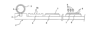
図1は本発明の製造方法を実施するカラーフィルタ製造装置の一例を示し、図2、図3はプロセスの概略を説明する図である。カラーフィルタ製造装置1は、インク受容層材料を定量塗布できる塗布ユニット2、塗布ユニット2からインク受容層材料の塗布を受けてインク受容層3を支持する支持部材4、支持部材4上のインク受容層3から不要な部分を取り除く剥離部材5、支持部材4上に残ったインク受容層材料からなるインク受容層パターン31が転写されて後述のインク受容層パターン6が形成される透明基板7を支持する固定ユニット8、透明基板7上のインク受容層パターン6にインクを付与するインクジェットユニット9から構成されている。
Embodiments of the present invention will be described below with reference to the drawings, but the present invention is not limited thereto.
FIG. 1 shows an example of a color filter manufacturing apparatus for carrying out the manufacturing method of the present invention, and FIGS. 2 and 3 are diagrams for explaining the outline of the process. The color filter manufacturing apparatus 1 includes an
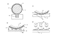
カラーフィルタ製造装置1によりカラーフィルタを製造する方法を図2で説明する。まず、支持部材4の移動によって塗布ユニット2からインク受容層材料を受け、その表面上にインク受容層3を形成した後、支持部材4が剥離部材5側に移動し、この剥離部材5を用いて、インク受容層3の不要部分(インク受容層パターンのネガパターン)を支持部材4から剥離除去し、支持部材4上に所望のインク受容層材料を残存形成させたインク受容層パターン31を得る。そして、そのインク受容層パターン31を有した支持部材4が固定ユニット8側に移動し、さらに透明基板7に接触移動してその透明基板7上にインク受容層パターン31を転写して、インク受容層パターン6を形成する(インク受容層形成工程)。
A method of manufacturing a color filter by the color filter manufacturing apparatus 1 will be described with reference to FIG. First, after receiving the ink receiving layer material from the
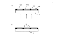
次に、透明基板7に対してインクジェットユニット9が対応位置し、透明基板7上のインク受容層パターン6にインクジェット方式によりインク受容層パターン6のそれぞれに対応するカラーフィルタ構成色(赤色(R)、緑色(G)、青色(B))の着色インクを吐出した後、加熱、光照射などの方法により着色部を硬化させることにより、着色層10R、10G、10Bを形成する(カラーフィルタパターン形成工程)。
Next, the
黒色遮光層を続いて形成するには、図3のように前記の着色層10R、10G、10Bを有する透明基板7上に図示しないスピンコーター、スリットコーター、ダイコーター等公知の塗布装置を使用して感光性の黒色遮光層12を形成し、該黒色遮光層の裏側から露光硬化し、その後現像処理により未露光部分を除去することにより、着色層の間に黒色遮光層のパターン13を形成する。露光にはUV光など用いるのが好適である。その後、黒色遮光層のパターン13を加熱処理によりさらに硬化しても良い(黒色遮光層形成工程)。
In order to subsequently form the black light-shielding layer, a known coating apparatus such as a spin coater, slit coater, die coater (not shown) is used on the
以上の工程により、カラーフィルタ構成色それぞれのフィルタパターンを組み合わせてなるカラーフィルタが得られる。 Through the above steps, a color filter obtained by combining the filter patterns of the color filter constituent colors is obtained.
上記カラーフィルタ製造装置1において支持部材4は金属ロールで構成すると、強度が高く、剥離部材との剥離除去に際して適正にインク受容層の除去がおこなわれるため、正確なパターンが得られるので好適である。また、支持部材4の表面を樹脂薄膜11で被覆すれば、インク受容層材料の盛りが安定し、インク受容層の層厚が処理を要することなくその支持部材表面で一定になる。さらに前記樹脂薄膜11がインク受容層材料の塗布性の優れる材料、詳しくは樹脂薄膜表面11の表面のインク受容層材料に対する接触角が10°以下であることがより好ましい。接触角が10°より大きい場合、樹脂薄膜表面11でインク受容層材料のハジキが発生しやすくなり、均一な塗膜を得ることが難しい。
In the color filter manufacturing apparatus 1, it is preferable that the
樹脂薄膜11の材料には、インク受容層材料との組み合せで好適に選択され、高分子フィルムやゴムのようにある程度の柔軟性を有する材料で構成されることが好ましく、例えば、フッ素樹脂、ポリビニルアルコール、ポリアクリレート、ポリカーボネート、ポリオレフィン、ポリメタクリル酸メチル、ポリエチレンテレフタレート、ポリアミド、ポリ塩化ビニル、ポリ塩化ビニリデン、エチレン-酢酸ビニル共重合体、ポリエーテルスルホン、シリコーン系エラストマー、フッ素系エラストマー、ブチルゴム、エチレンプロピレンゴムまたはこれらの混合物あるいは積層物などが挙げられる。
The material of the resin
本発明の塗布ユニット2には、スリットコーター、ダイコーター等公知の塗布装置を使用することができる。
A known coating apparatus such as a slit coater or a die coater can be used for the
本発明において剥離部材5には、平板状あるいはロール状の金属板、ガラス版、樹脂版などを使用することができる。剥離部材5は凸部5aがインク受容層パターンのネガパターンになるように加工され、この凸部5aに支持部材4のインク受容層3を接しさせ、離れる時点でネガパターンの不要部分が凸部5aにて除去される。
上記透明基板7には、ガラス基板、石英基板、プラスチック基板等が使用できる。
In the present invention, the
As the
本発明におけるインク受容層材料は、高分子樹脂を含む材料で形成される。前記高分子樹脂は、特に限定されるものではないが、透明であれば使用することができる。この高分子樹脂の具体例を挙げると、アクリル樹脂、ポリエチレン、ポリウレタン、ビニル樹脂、スチレン樹脂、エステル樹脂等が挙げられるが、これに限定されるものではない。また、インク受容層には必要に応じて、フィラー等を混合させることが可能である。 The ink receiving layer material in the present invention is formed of a material containing a polymer resin. The polymer resin is not particularly limited, but can be used as long as it is transparent. Specific examples of the polymer resin include acrylic resin, polyethylene, polyurethane, vinyl resin, styrene resin, and ester resin, but are not limited thereto. Moreover, a filler etc. can be mixed with an ink receiving layer as needed.
本発明における黒色遮光層材料には、樹脂(光重合性モノマー、光重合開始剤を含む)、黒色遮光材、分散剤、溶媒等を主成分とする黒色の感光性樹脂組成物を用い、フォトリソグラフィ法等により黒色遮光層を形成することができる。 As the black light shielding layer material in the present invention, a black photosensitive resin composition mainly composed of a resin (including a photopolymerizable monomer and a photopolymerization initiator), a black light shielding material, a dispersant, a solvent, and the like is used. A black light shielding layer can be formed by lithography or the like.
黒色遮光層材料の黒色遮光材としては、黒色顔料、黒色染料、無機材料などであり、有機顔料、カーボンブラック、アニリンブラック、黒鉛、酸化チタン、鉄黒などを混合して用いられるものである。 Examples of the black light shielding material for the black light shielding layer material include black pigments, black dyes, and inorganic materials, and organic pigments, carbon black, aniline black, graphite, titanium oxide, iron black, and the like are used in combination.
黒色遮光層材料の樹脂には、カゼイン、ゼラチン、ポリビニルアルコール、カルボキシメチルアセタール、ポリイミド樹脂、アクリル樹脂、エポキシ樹脂、メラミン樹脂などが適宜選択される。耐熱性や耐光性が要求される際にはアクリル樹脂が好ましい。 Casein, gelatin, polyvinyl alcohol, carboxymethyl acetal, polyimide resin, acrylic resin, epoxy resin, melamine resin, and the like are appropriately selected as the resin for the black light shielding layer material. An acrylic resin is preferred when heat resistance and light resistance are required.
黒色遮光層材料の溶媒としては、黒色樹脂組成物の塗布性、分散安定性などの点から、適宜選択して使用されるものであり、トルエン、キシレン、エチルセロソルブ、エチルセロソルブアセテート、ジクライム、シクロヘキサノンなどが挙げられる。 The solvent for the black light-shielding layer material is appropriately selected and used from the viewpoints of the coating properties and dispersion stability of the black resin composition, and includes toluene, xylene, ethyl cellosolve, ethyl cellosolve acetate, diclime, and cyclohexanone. Etc.
黒色遮光層材料の分散剤としては、非イオン性界面活性剤では、例えばポリオキシエチレンアルキルエーテルなど、またイオン性界面活性剤では、例えばアルキルベンゼンスルホン酸ナトリウム、ポリ脂肪酸塩、脂肪酸塩アルキルリン酸塩、テトラアルキルアンモニウム塩など、その他に有機顔料誘導体、ポリエステルなどが挙げられる。分散剤は単独で使用してもよくまた二種類以上を混合して使用しても良い。 As the dispersant for the black light-shielding layer material, nonionic surfactants such as polyoxyethylene alkyl ether and the like, and ionic surfactants such as sodium alkylbenzene sulfonate, poly fatty acid salt, fatty acid salt alkyl phosphate, etc. In addition, tetraalkylammonium salts and the like, and organic pigment derivatives, polyesters, and the like. A dispersing agent may be used independently and may mix and use two or more types.
本発明の着色インクの材料は、着色顔料、樹脂、分散剤、溶媒などで構成される。
着色剤として使用する顔料の具体例としては、Pigment Red9、19、38、43、97、122、123、144、149、166、168、177、179、180、192、215、216、208、216、217、220、223、224、226、227、228、240、Pigment Blue 15、15:6、16、22、29、60、64、Pigment Green7、36、Pigment Red 20、24、86、81、83、93、108、109、110、117、125、137、138、139、147、148、153、154、166、168、185、Pigment Orange36、Pigment Violet23などを挙げることができるが、これらに限定されるものではない。さらに、これらは要望の色相を得るために2種類以上を混合して用いても構わない。
The material of the colored ink of the present invention includes a color pigment, a resin, a dispersant, a solvent, and the like.
Specific examples of the pigment used as the colorant include
着色インクに使用する溶剤種としてはインクジェット方式における適性の表面張力範囲40mN/m以下で、且つ、沸点が130℃以上のものが好ましい。表面張力が40mN/m以上であるとインクジェット吐出時のドット形状の安定性に著しい悪影響を及ぼし、また、沸点が130℃以下であるとノズル近傍での乾燥性が著しく高くなり、その結果、ノズル詰まり等の不良発生を招くので好ましくない。具体的には、2−メトキシエタノール、2−エトキシエタノール、2−ブトキシエタノール、2−エトキシエチルアセテート、2−ブトキシエチルアセテート、2−メトキシエチルアセテート、2−エトキシエチルエーテル、2−(2−エトキシエトキシ)エタノール、2−(2−ブトキシエトキシ)エタノール、2−(2−エトキシエトキシ)エチルアセテート、2−(2−ブトキシエトキシ)エチルアセテート、2−フェノキシエタノール、ジエチレングリコールジメチルエーテルなどを挙げることができるが、これらに限定されるものではなく、上記要件を満たす溶剤なら用いることができる。また、必要に応じて2種類以上の溶剤を混合して用いても構わない。
As the solvent species used for the colored ink, those having an appropriate surface tension range of 40 mN / m or less in an ink jet system and a boiling point of 130 ° C. or more are preferable. When the surface tension is 40 mN / m or more, the dot shape stability at the time of ink jet ejection is significantly adversely affected. When the boiling point is 130 ° C. or less, the drying property in the vicinity of the nozzle is remarkably increased. This is not preferable because it causes clogging and other defects. Specifically, 2-methoxyethanol, 2-ethoxyethanol, 2-butoxyethanol, 2-ethoxyethyl acetate, 2-butoxyethyl acetate, 2-methoxyethyl acetate, 2-ethoxyethyl ether, 2- (2-ethoxy Ethoxy) ethanol, 2- (2-butoxyethoxy) ethanol, 2- (2-ethoxyethoxy) ethyl acetate, 2- (2-butoxyethoxy) ethyl acetate, 2-phenoxyethanol, diethylene glycol dimethyl ether, etc. The solvent is not limited to these, and any solvent that satisfies the above requirements can be used. Moreover, you may mix and
着色インクに使用する樹脂には、カゼイン、ゼラチン、ポリビニルアルコール、カルボキシメチルアセタール、ポリイミド樹脂、アクリル樹脂、エポキシ樹脂、メラニン樹脂などが用いられ、色素との関係にて適宜選択される。耐熱性や耐光性が要求される際にはアクリル樹脂が好ましい。 As the resin used for the colored ink, casein, gelatin, polyvinyl alcohol, carboxymethyl acetal, polyimide resin, acrylic resin, epoxy resin, melanin resin, and the like are used, and are appropriately selected in relation to the pigment. An acrylic resin is preferred when heat resistance and light resistance are required.
樹脂への色素の分散を向上させるために、分散剤を用いてもよく、分散剤として、非イオン性界面活性剤としては、例えば、ポリオキシエチレンアルキルエーテルなど、また、イオン性界面活性剤としては、例えば、アルキルベンゼンスルホン酸ナトリウム、ポリ脂肪酸塩、脂肪酸塩アルキルリン酸塩、テトラアルキルアンモニウム塩など、その他に、有機顔料誘導体、ポリエステルなどがあげられる。分散剤は一種類を単独で使用してもよく、また、二種類以上を混合して使用してもよい。溶媒としては溶解性の他に経時安定性、乾燥性などが要求され、色素、樹脂との関係にて適宜選択される。 In order to improve the dispersion of the dye in the resin, a dispersant may be used. As the dispersant, as the nonionic surfactant, for example, polyoxyethylene alkyl ether, etc., and as the ionic surfactant Examples thereof include sodium alkylbenzene sulfonate, poly fatty acid salt, fatty acid salt alkyl phosphate, tetraalkyl ammonium salt, and other organic pigment derivatives and polyester. One type of dispersant may be used alone, or two or more types of dispersants may be mixed and used. The solvent is required to have stability over time, drying property, etc. in addition to solubility, and is appropriately selected in relation to the dye and the resin.
着色インクを供給するインクジェット装置としては、インク吐出方法の相違によりピエゾ変換方式と熱変換方式があり、特にピエゾ変換方式が好適である。インクの粒子化周波数は5〜100KHz程度、ノズル径としては5〜80μm程度,ヘッドを3個配置し、1ヘッドにノズルを60〜500個組み込んだ装置が好適である。 As an ink jet apparatus for supplying colored ink, there are a piezo conversion method and a heat conversion method depending on the ink discharge method, and the piezo conversion method is particularly preferable. A device in which the ink particleization frequency is about 5 to 100 KHz, the nozzle diameter is about 5 to 80 μm, three heads are arranged, and 60 to 500 nozzles are incorporated in one head is suitable.
以下に本発明の実施例を具体的に説明する。
(インク受容層の形成)
インク受容層の樹脂材料として、ポリメタクリル酸メチルを使用した。支持部材には、表面にポリビニルアルコールを被覆した金属ロールを使用した。剥離部材には、表面を所定の凹凸に加工した平板状ガラスを使用した。
ポリメタクリル酸メチルを支持部材上にスリットコーター法により厚さ7μmになるよう塗布した後、剥離部材によって不要部分を除去し、支持部材に残ったインク受容層パターンを無アルカリガラス(コーニング社製、品番1737)上に転写し、インク受容層のパターンを形成した。
Examples of the present invention will be specifically described below.
(Formation of ink receiving layer)
Polymethyl methacrylate was used as a resin material for the ink receiving layer. A metal roll having a surface coated with polyvinyl alcohol was used as the support member. As the peeling member, flat glass whose surface was processed into predetermined irregularities was used.
After applying polymethyl methacrylate onto the support member so as to have a thickness of 7 μm by the slit coater method, unnecessary portions are removed by a peeling member, and the ink receiving layer pattern remaining on the support member is made of alkali-free glass (manufactured by Corning, No. 1737) and an ink receiving layer pattern was formed.
(着色インクの調製)
メタクリル酸20部、メチルメタクリレート10部、ブチルメタクリレート55部、ヒドロキシエチルメタクリレート15部を乳酸ブチル300gに溶解し、窒素雰囲気下でアゾビスイソブチルニトリル0.75部を加え70℃にて5時間の反応によりアクリル共重合樹脂を得た。得られたアクリル共重合樹脂を、樹脂濃度が10%になるようにプロピレングリコールモノメチルエーテルアセテートで希釈し、アクリル共重合樹脂の希釈液とした。この希釈液80.1gに対し、顔料19.0g、分散剤0.9gを添加して、3本ロールにて混練し、赤色、緑色、青色の各着色ワニスを得た。この各着色ワニスを、プロピレングリコールモノメチルエーテルアセテートで顔料濃度が12〜15%、粘度が15cpsになるように調整し、R、G、B着色インクを得た。
(Preparation of colored ink)
20 parts of methacrylic acid, 10 parts of methyl methacrylate, 55 parts of butyl methacrylate and 15 parts of hydroxyethyl methacrylate are dissolved in 300 g of butyl lactate, and 0.75 part of azobisisobutylnitrile is added in a nitrogen atmosphere, and the reaction is carried out at 70 ° C. for 5 hours. As a result, an acrylic copolymer resin was obtained. The obtained acrylic copolymer resin was diluted with propylene glycol monomethyl ether acetate so that the resin concentration would be 10% to obtain a diluted solution of the acrylic copolymer resin. 19.0 g of pigment and 0.9 g of dispersant were added to 80.1 g of this diluted solution, and kneaded with three rolls to obtain red, green and blue colored varnishes. Each colored varnish was adjusted with propylene glycol monomethyl ether acetate so that the pigment concentration was 12 to 15% and the viscosity was 15 cps to obtain R, G and B colored inks.
(パターン状着色層の形成)
前記のインク受容層をパターン形成したガラス基板に対して、該インク受容層上に上記R、G、B各色の着色インクを使用し、12pl、180dpiヘッドを搭載したインクジェット印刷装置により、赤色(R)、緑色(G)、青色(B)各々のパターン状着色層を形成した。
(Formation of patterned colored layer)
A glass substrate on which the ink receiving layer is patterned is colored red (R) by using an ink jet printing apparatus equipped with a 12 pl, 180 dpi head using colored inks of the above R, G, B colors on the ink receiving layer. ), Green (G), and blue (B) pattern colored layers were formed.
(黒色遮光層の形成)
上記インク受容層に着色インクを付与しパターン状着色層を形成したガラス基板上に、カーボンブラックを含有したレジスト材(新日鉄化学社製ブラックマトリクス用ネガ型レジストインキ「V−259 BK739P」)をスピンコートにより膜厚1.5μmになるように塗布し、レジスト材を塗布した面の対抗面側から露光することにより、インク受容層間隙のレジスト材を硬化し、未硬化部分を現像処理により除去した後、加熱処理によりレジスト材を硬化し、黒色遮光層を形成した。
このようにして得られたカラーフィルタは、面内の色ムラも少なく、パターニングがシャープなカラーフィルタであった。
(Formation of black shading layer)
Spin a resist material containing carbon black (negative resist ink for black matrix “V-259 BK739P” manufactured by Nippon Steel Chemical Co., Ltd.) on a glass substrate on which a colored ink is applied to the ink receiving layer to form a patterned colored layer. The coating was applied to a film thickness of 1.5 μm by coating, and the resist material in the gap of the ink receiving layer was cured by exposing from the opposite side of the surface coated with the resist material, and the uncured portion was removed by development processing. Thereafter, the resist material was cured by heat treatment to form a black light shielding layer.
The color filter thus obtained was a color filter with little in-plane color unevenness and sharp patterning.
1 ・・ カラーフィルタ製造装置
2 ・・ 塗布ユニット
3 ・・ インク受容層
4 ・・ 支持部材
5 ・・ 剥離部材
6 ・・ インク受容層
7 ・・ 透明基板
8 ・・ 固定ユニット
9 ・・ インクジェットユニット
10R、10G、10B ・・ 着色層
11 ・・ 樹脂薄膜
12 ・・ 黒色遮光層
13 ・・ 黒色遮光層のパターン
31 ・・ インク受容層パターン
1 .. Color
Claims (5)
Priority Applications (1)
| Application Number | Priority Date | Filing Date | Title |
|---|---|---|---|
| JP2005012486A JP2006201435A (en) | 2005-01-20 | 2005-01-20 | Color filter manufacturing method and color filter |
Applications Claiming Priority (1)
| Application Number | Priority Date | Filing Date | Title |
|---|---|---|---|
| JP2005012486A JP2006201435A (en) | 2005-01-20 | 2005-01-20 | Color filter manufacturing method and color filter |
Publications (1)
| Publication Number | Publication Date |
|---|---|
| JP2006201435A true JP2006201435A (en) | 2006-08-03 |
Family
ID=36959490
Family Applications (1)
| Application Number | Title | Priority Date | Filing Date |
|---|---|---|---|
| JP2005012486A Pending JP2006201435A (en) | 2005-01-20 | 2005-01-20 | Color filter manufacturing method and color filter |
Country Status (1)
| Country | Link |
|---|---|
| JP (1) | JP2006201435A (en) |
-
2005
- 2005-01-20 JP JP2005012486A patent/JP2006201435A/en active Pending
Similar Documents
| Publication | Publication Date | Title |
|---|---|---|
| JP2007177179A (en) | Ink, color filter, manufacturing method thereof, and display device | |
| JP4623500B2 (en) | Manufacturing method of color filter | |
| JP2009092735A (en) | Color filter defect correction method | |
| JP4385641B2 (en) | Manufacturing method of color filter | |
| JP2006201435A (en) | Color filter manufacturing method and color filter | |
| JP4320806B2 (en) | Color filter for display device, method for manufacturing the same, and display device | |
| JP2007148041A (en) | Color filter manufacturing method, color filter, and display device | |
| JP4363043B2 (en) | Color filter for display device | |
| JPWO2007077751A1 (en) | Ink composition for inkjet color filter, color filter, method for producing the same, and liquid crystal display device | |
| JP3700398B2 (en) | Color filter for display device and display device | |
| JP4396150B2 (en) | Manufacturing method of color filter for display device | |
| JP4466219B2 (en) | Color filter manufacturing method and color filter comprising this manufacturing method | |
| JP2007094307A (en) | Color filter and manufacturing method thereof | |
| JP6119737B2 (en) | Display color filter | |
| JP5098670B2 (en) | Manufacturing method of color filter | |
| JP2007177015A (en) | Active energy ray-curable ink for color filter, color filter, method for producing the same, and liquid crystal display device | |
| JP2006017980A (en) | Manufacturing method of color filter | |
| JP2007256805A (en) | Color filter and manufacturing method thereof | |
| JP3903683B2 (en) | Color filter manufacturing method, color filter, image display device, and image input device | |
| JP4572675B2 (en) | Manufacturing method of color filter | |
| JP4270211B2 (en) | Color filter for display device and manufacturing method thereof | |
| JP2004294617A (en) | Method for manufacturing color filter for display device | |
| JP4507286B2 (en) | Color filter for display device and reflection type display device | |
| JPH1016396A (en) | Formation of colored pattern on substrate | |
| JP2004325617A (en) | Color filter substrate and color filter |