JP2006196474A - Spark plug - Google Patents
Spark plug Download PDFInfo
- Publication number
- JP2006196474A JP2006196474A JP2006116130A JP2006116130A JP2006196474A JP 2006196474 A JP2006196474 A JP 2006196474A JP 2006116130 A JP2006116130 A JP 2006116130A JP 2006116130 A JP2006116130 A JP 2006116130A JP 2006196474 A JP2006196474 A JP 2006196474A
- Authority
- JP
- Japan
- Prior art keywords
- mol
- component
- insulator
- terms
- glaze layer
- Prior art date
- Legal status (The legal status is an assumption and is not a legal conclusion. Google has not performed a legal analysis and makes no representation as to the accuracy of the status listed.)
- Pending
Links
Images


Abstract
Description
本発明はスパークプラグに関する。 The present invention relates to a spark plug.
自動車エンジン等の内燃機関の点火用に使用されるスパークプラグは、一般に、接地電極が取り付けられる主体金具の内側に、アルミナ系セラミック等で構成された絶縁体が配置され、その絶縁体の内側に中心電極が配置された構造を有する。絶縁体は主体金具の後方側開口部から軸方向に突出し、その突出部の内側に端子金具が配置され、これがガラスシール工程により形成される導電性ガラスシール層や抵抗体等を介して中心電極と接続される。そして、その端子金具を介して高圧を印加することにより、接地電極と中心電極との間に形成されたギャップに火花放電が生ずることとなる。 A spark plug used for ignition of an internal combustion engine such as an automobile engine is generally provided with an insulator made of alumina ceramic or the like inside a metal shell to which a ground electrode is attached, and inside the insulator. It has a structure in which a center electrode is arranged. The insulator protrudes in the axial direction from the rear opening of the metal shell, and a terminal metal fitting is arranged inside the protruding portion, and this is a central electrode through a conductive glass seal layer or a resistor formed by the glass sealing process. Connected. Then, by applying a high voltage via the terminal fitting, a spark discharge is generated in the gap formed between the ground electrode and the center electrode.
ところが、プラグ温度が高くなったり、周囲の湿度が上昇したりするなどの条件が重なると、高圧印加してもギャップに飛火せず、絶縁体突出部の表面を回り込む形で端子金具と主体金具との間で放電する、いわゆるフラッシュオーバ現象が生じることがある。そのため、一般に使用されているほとんどのスパークプラグにおいては、主にこのフラッシュオーバ現象防止のために絶縁体表面に釉薬層が形成されている。他方、釉薬層は、絶縁体表面を平滑化して汚染を防止したり、化学的あるいは機械的強度を高めたりするといった役割も果たす。 However, if the conditions such as the temperature of the plug rises or the ambient humidity rises, the terminal metal fitting and the main metal fitting do not ignite the gap even when a high voltage is applied and wrap around the surface of the insulator protrusion. In some cases, a so-called flashover phenomenon occurs in which discharge occurs between the two. Therefore, in most spark plugs that are generally used, a glaze layer is formed on the insulator surface mainly to prevent this flashover phenomenon. On the other hand, the glaze layer also plays a role of smoothing the surface of the insulator to prevent contamination and increasing chemical or mechanical strength.
スパークプラグ用のアルミナ系絶縁体の場合、従来は、ケイ酸塩ガラスに比較的多量のPbOを配合して軟化点を低下させた鉛ケイ酸塩ガラス系の釉薬を使用してきたが、環境保護に対する関心が地球規模で高まりつつある近年では、Pbを含有する釉薬は次第に敬遠されるようになってきている。例えばスパークプラグが多量に使用される自動車業界においては、廃棄スパークプラグによる環境への影響を考慮して、Pb含有釉薬を使用したスパークプラグの使用は将来全廃しようとの検討も進められている。 In the case of alumina-based insulators for spark plugs, lead silicate glass glazes that have a relatively low softening point by blending a relatively large amount of PbO with silicate glass have been used. In recent years, there has been an increasing interest in glazing, and glazes containing Pb are increasingly shunned. For example, in the automobile industry in which spark plugs are used in large quantities, in consideration of the environmental impact of discarded spark plugs, the use of spark plugs containing Pb-containing glazes is being studied to eliminate them in the future.
しかしながら、そのようなPb含有釉薬の代替品として検討されている硼珪酸ガラスやアルカリ硼珪酸ガラス系の無鉛釉薬は、ガラス転移点が高かったり、あるいは絶縁抵抗が不足したりする等の不具合が避けがたかった。この問題を解決するために、特開平11−43351号公報には、Zn成分の組成調整等により、釉焼時の流動性を低下させることなくガラス安定化を図った無鉛釉薬の組成が、また、特開平11−106234号公報には、アルカリ成分の共添加効果により絶縁抵抗の向上を図った無鉛釉薬の組成がそれぞれ開示されている。 However, borosilicate glass and alkali borosilicate glass-based lead-free glazes that are being considered as substitutes for such Pb-containing glazes avoid problems such as high glass transition points or insufficient insulation resistance. I wanted to. In order to solve this problem, Japanese Patent Application Laid-Open No. 11-43351 discloses a composition of a lead-free glaze that achieves glass stabilization without reducing fluidity during sintering by adjusting the composition of the Zn component, etc. JP-A-11-106234 discloses a composition of a lead-free glaze in which the insulation resistance is improved by the co-addition effect of an alkali component.
ところで、スパークプラグ用の釉薬層は、絶縁体表面への汚れ付着等を防止したり、沿面放電耐電圧を向上させてフラッシュオーバを防いだりするほか、破壊起点になりやすい絶縁体表面の欠陥を埋めて強度向上を図る機能も果たしている。 しかしながら、特に高出力化が著しい最近の内燃機関では、作動中にスパークプラグが受ける振動や衝撃もかなり大きく、釉薬層を形成していても絶縁体の折損等が問題になることもある。また、スパークプラグのシリンダヘッドへの取り付け時(特に、インパクトレンチ等の動力工具を用いた組み付け時)に、過剰な締め付けトルクが付加されたりすると、やはり絶縁体が折損することがある。また、エンジンの高性能化に伴いスパークプラグへの印加電圧も高くなってきていることから、釉薬に対してもより厳しい環境に耐えうる絶縁性能が要求されているが、前述の特開平11−106234号公報や特開平11−106234号公報に開示された釉薬組成では、絶縁性能と機械的性質とを両立させるための釉薬組成が必ずしも十分に検討されているとはいえない問題がある。 By the way, the glaze layer for spark plugs prevents dirt from adhering to the surface of the insulator, improves creeping discharge withstand voltage to prevent flashover, and eliminates defects on the surface of the insulator that are prone to breakage. It also fulfills the function of filling and improving strength. However, in a recent internal combustion engine whose output is particularly high, vibrations and impacts received by the spark plug during operation are considerably large, and even if a glaze layer is formed, breakage of the insulator may become a problem. In addition, if an excessive tightening torque is applied when the spark plug is attached to the cylinder head (particularly when assembling using a power tool such as an impact wrench), the insulator may still be broken. In addition, since the voltage applied to the spark plug has been increased along with the enhancement of the engine performance, there is a demand for insulation performance that can withstand glazes even in a more severe environment. In the glaze composition disclosed in Japanese Patent No. 106234 and Japanese Patent Laid-Open No. 11-106234, there is a problem that the glaze composition for achieving both insulating performance and mechanical properties is not always sufficiently studied.
本発明の課題は、Pb成分の含有量が少なく、しかも比較的低温で釉焼可能であって絶縁性に優れ、しかも平滑な釉焼面を得やすく釉薬層付き絶縁体の機械的な強度も向上できる釉薬層を有したスパークプラグを提供することを課題とする。 The problem of the present invention is that the content of the Pb component is small, it can be fired at a relatively low temperature, has excellent insulating properties, and it is easy to obtain a smooth fired surface, and the mechanical strength of the insulator with a glaze layer is also high. It is an object to provide a spark plug having a glaze layer that can be improved.
上記の課題を解決するために本発明のスパークプラグは、中心電極と主体金具との間にアルミナ系セラミックからなる絶縁体を配したスパークプラグにおいて、その絶縁体の表面の少なくとも一部を覆う形態で酸化物主体の釉薬層が形成され、該釉薬層が、
Pb成分の含有量がPbO換算にて1mol%以下とされ、
Si成分をSiO2に酸化物換算した値にて15〜60mol%、B成分をB2O3に酸化物換算した値にて22〜50mol%、Zn成分をZnOに酸化物換算した値にて10〜30mol%、Ba及び/又はSr成分を、BaOないしSrOに酸化物換算した値にて合計で0.5〜35mol%含有し、
F成分の含有量が1mol%以下であり、
Al成分をAl2O3に酸化物換算した値にて0.1〜5mol%含有し、
アルカリ金属成分として、NaはNa2O、KはK2O、LiはLi2Oに酸化物換算した値にて、Liを必須とする1種又は2種以上を合計で1.1〜10mol%の範囲にて含有し、
かつ、Li成分の含有量範囲がLi2Oに酸化物換算した値にて1.1〜6mol%とされたことを特徴とする。
In order to solve the above problems, a spark plug of the present invention is a spark plug in which an insulator made of an alumina-based ceramic is disposed between a center electrode and a metal shell, and covers at least a part of the surface of the insulator. An oxide-based glaze layer is formed, and the glaze layer is
The content of the Pb component is 1 mol% or less in terms of PbO,
The Si component is converted to SiO 2 in an oxide conversion value of 15 to 60 mol%, the B component is converted into an oxide conversion value into B 2 O 3 , and the Zn component is converted into an oxide conversion value into ZnO. 10 to 30 mol%, Ba and / or Sr components are contained in a total of 0.5 to 35 mol% in terms of oxide conversion to BaO or SrO,
The content of the F component is 1 mol% or less,
The Al component contained 0.1 to 5 mol% in terms of oxide values to Al 2 O 3,
As an alkali metal component, Na is Na 2 O, K is K 2 O, Li is a value in terms of oxide converted to Li 2 O, and a total of 1.1 to 10 mol of one or two or more essential components of Li. % In the range,
And, wherein the range of content of Li component is a 1.1~6Mol% in terms of oxide value to Li 2 O.
上基本発明のスパークプラグにおいては、前述の環境問題への適合性を図るため、使用する釉薬が、Pb成分の含有量がPbO換算にて1.0mol%以下とすることを前提とする(以下、このレベルにPb成分含有量が低減された釉薬を無鉛釉薬と称する)。また、釉薬層中にPb成分が価数の低いイオン(例えばPb2+)の形で含有されていると、コロナ放電等によりこれが価数の高いイオン(例えばPb3+)に酸化され、釉薬層の絶縁性が低下して耐フラッシュオーバ性が損なわれる場合もあるので、Pb含有量を上記のように削減することはこの観点においても好都合である。なお、Pbの含有量は望ましくは0.1mol%以下、より望ましくは実質的に含有しない(ただし、釉薬原料等から不可避的に混入するものを除く)のがよい。 In the spark plug of the above basic invention, in order to achieve compatibility with the above-mentioned environmental problems, the glaze used is premised on the content of the Pb component being 1.0 mol% or less in terms of PbO (hereinafter referred to as “PbO”). The glaze whose Pb component content is reduced to this level is referred to as a lead-free glaze). Further, if the Pb component is contained in the glaze layer in the form of ions with a low valence (for example, Pb 2+ ), this is oxidized to ions with a high valence (for example, Pb 3+ ) by corona discharge, etc. Since the insulating properties may be reduced and the flashover resistance may be impaired, it is advantageous in this respect to reduce the Pb content as described above. The Pb content is desirably 0.1 mol% or less, and more desirably substantially not contained (excluding those inevitably mixed from glaze raw materials).
しかしながら、本発明者らが検討したところ、釉薬層中のPb成分の含有量が小さくなると、釉薬層の機械的強度、特に耐衝撃性が相対的に低下しやすいことが判明した。そこで、Si成分、B成分、Zn成分、Ba及び/又はSr成分、Al成分、さらにLi成分を必須とするアルカリ金属成分を上記の範囲にて含有させることにより、比較的低温で釉焼可能であって絶縁性に優れ、かつ平滑な釉焼面を得やすく釉薬層付き絶縁体の機械的な強度、特に耐衝撃性を大幅に向上できることを見出し、本発明を完成させるに至った。これにより、高出力内燃機関に取り付けられた場合においても、作動中に振動等によりスパークプラグの絶縁体が折損したり、スパークプラグのシリンダヘッドへの取り付け時(特に、インパクトレンチ等の動力工具を用いた組み付け時)に、多少過剰な締め付けトルクが付加されても絶縁体が折損したりしにくくなる。 However, as a result of studies by the present inventors, it has been found that when the content of the Pb component in the glaze layer decreases, the mechanical strength, particularly impact resistance, of the glaze layer tends to be relatively lowered. Therefore, it can be sintered at a relatively low temperature by containing an Si component, a B component, a Zn component, a Ba and / or Sr component, an Al component, and an alkali metal component essential for the Li component in the above range. Thus, the inventors have found that the mechanical strength, in particular, the impact resistance of the insulator with a glaze layer can be greatly improved because it is easy to obtain a smooth glazed surface with excellent insulation, and the present invention has been completed. As a result, even when mounted on a high-power internal combustion engine, the spark plug insulation breaks during operation, or when the spark plug is mounted on the cylinder head (especially, a power tool such as an impact wrench is used). Even when a slightly excessive tightening torque is applied during the assembly), the insulator is less likely to break.
以下、上記スパークプラグの構成における釉薬層の各構成成分の、含有量範囲の臨界的意味について説明する。Si成分は、ガラス質の釉薬層の骨格形成成分であり、また、釉薬層の絶縁性確保のためにも欠かすことのできない成分である。その含有量が15mol%未満になると、十分な絶縁性能の確保が困難となる場合がある。また、Si成分が60mol%を超えると、釉焼が困難となる場合がある。なお、該Si成分含有量は、より望ましくは25〜40mol%の範囲で設定するのがよい。 Hereinafter, the critical meaning of the content range of each component of the glaze layer in the configuration of the spark plug will be described. The Si component is a skeleton forming component of the vitreous glaze layer, and is also an indispensable component for ensuring the insulating properties of the glaze layer. If the content is less than 15 mol%, it may be difficult to ensure sufficient insulation performance. Moreover, when Si component exceeds 60 mol%, sinter firing may become difficult. The Si component content is more desirably set in the range of 25 to 40 mol%.
また、B成分も、Si成分とともにガラス質の釉薬層の、骨格形成成分の主体となるものであり、かつSi成分と組み合わされることによって釉薬軟化点を低下させ、釉焼時の流れ性を向上させて平滑な釉焼面を得やすくする働きもなす。ただし、B成分含有量が22mol%未満になると、釉薬の軟化点が上昇し、釉焼が困難となる場合がある。他方、B成分含有量が55mol%を超えると、釉チヂレ等の外観不良が引き起こされやすくなる。あるいは、釉薬スラリーの耐水性が損なわれる場合がある。また、他の成分の含有量によっては、釉薬層の失透、絶縁性の低下あるいは下地との熱膨張係数不適合といった問題についても懸念が生ずる場合がある。なお、該B成分含有量は、望ましくは25〜35mol%の範囲で設定するのがよい。 In addition, the B component is the main component of the skeleton forming component of the vitreous glaze layer together with the Si component, and when combined with the Si component, the glaze softening point is lowered and the flowability during calcination is improved. It also makes it easy to obtain a smooth glazed surface. However, when the B component content is less than 22 mol%, the softening point of the glaze increases, and smoldering may become difficult. On the other hand, when the B component content exceeds 55 mol%, appearance defects such as wrinkles tend to be caused. Or the water resistance of the glaze slurry may be impaired. Further, depending on the content of other components, there may be a concern about problems such as devitrification of the glaze layer, deterioration of insulating properties, or incompatibility with the thermal expansion coefficient with the base. The B component content is desirably set in the range of 25 to 35 mol%.
Zn成分含有量は、Pb成分に代わって釉焼時の流動性を高め、平滑な釉焼面を得やすくする働きを成す。また、一定量以上に配合することで、アルミナ系セラミックからなる絶縁体下地と釉薬層との熱膨張係数の差を縮小し、釉薬層への欠陥発生を防止するとともに、引張残留応力の残留レベルを抑制して、釉薬層付き絶縁体の強度、特に耐衝撃性を高める働きをなす。ただし、その含有量が10mol%未満になると、釉薬層の熱膨張係数が大きくなりすぎ、釉薬層に貫入等の欠陥が生じやすくなる場合がある。また、Zn成分が不足すれば釉焼が困難となる場合がある。他方、Zn成分の含有量が30mol%を超えると、失透により釉薬層に白濁等を生じやすくなる。Zn成分の含有量は、より望ましくは10〜20mol%の範囲にて調整されているのがよい。 The Zn component content increases the fluidity at the time of calcination instead of the Pb component, and makes it easy to obtain a smooth glazed surface. In addition, by blending more than a certain amount, the difference in thermal expansion coefficient between the insulator base made of alumina ceramic and the glaze layer is reduced, the occurrence of defects in the glaze layer is prevented, and the residual level of tensile residual stress Suppresses the strength of the insulator with the glaze layer, and in particular increases the impact resistance. However, when the content is less than 10 mol%, the thermal expansion coefficient of the glaze layer becomes too large, and defects such as penetration may easily occur in the glaze layer. Moreover, if the Zn component is insufficient, smoldering may be difficult. On the other hand, when the content of the Zn component exceeds 30 mol%, white turbidity or the like tends to occur in the glaze layer due to devitrification. The content of the Zn component is more desirably adjusted in the range of 10 to 20 mol%.
Ba成分ないしSr成分は、釉薬層の絶縁性向上に寄与するほか、強度の向上にも効果がある。その合計含有量が0.5mol%未満になると、釉薬の絶縁性が低下し、耐フラッシュオーバー性が損なわれることにつながる場合がある。他方、合計含有量が31mol%を超えると、釉薬層の熱膨張係数が高くなりすぎ、釉薬層に貫入等の欠陥が生じやすくなるほか、高温からの冷却時に釉薬層に引張応力が残留しやすくなり、釉薬層付き絶縁体の強度、例えば耐衝撃性が損なわれやすくなる。また、釉薬層が失透して白濁等も生じやすくなる。Ba及びSr成分の合計含有量は、絶縁性向上及び熱膨張係数調整の観点から、望ましくは0.5〜20mol%の範囲で設定するのがよく、特に前述のSi成分の範囲を25〜40mol%とした場合に効果が大きい。なお、Ba成分とSr成分とは、いずれか一方を単独で含有させてもよいし、両者を混合して含有してもよい。ただし、原料コスト的な面においては、より安価なBa成分の使用が有利である。 The Ba component or Sr component contributes to the improvement of the insulating properties of the glaze layer and is also effective in improving the strength. If the total content is less than 0.5 mol%, the insulating properties of the glaze may be reduced, leading to a loss of flashover resistance. On the other hand, if the total content exceeds 31 mol%, the thermal expansion coefficient of the glaze layer becomes too high, and defects such as penetration occur in the glaze layer, and tensile stress tends to remain in the glaze layer when cooled from a high temperature. Thus, the strength of the insulator with the glaze layer, such as impact resistance, is likely to be impaired. Further, the glaze layer is devitrified and white turbidity is likely to occur. The total content of the Ba and Sr components is preferably set in the range of 0.5 to 20 mol% from the viewpoint of improving the insulation and adjusting the thermal expansion coefficient. In particular, the range of the above-mentioned Si component is 25 to 40 mol. The effect is large when% is used. In addition, Ba component and Sr component may contain any one individually, and may mix and contain both. However, in terms of raw material cost, it is advantageous to use a cheaper Ba component.
なお、Ba成分及びSr成分は、使用原料によっては釉薬中にて酸化物以外の形態で存在する場合がある。例えば、BaSO4をBa成分源として用いた場合、S成分が釉薬層中に残留することがある。この硫黄成分は釉焼時に釉薬層の表面近くに濃化して、溶融釉薬の表面張力を低下させ、得られる釉薬層の平滑性を高めることができる場合がある。 Note that the Ba component and the Sr component may exist in a form other than the oxide in the glaze depending on the raw materials used. For example, when BaSO 4 is used as the Ba component source, the S component may remain in the glaze layer. This sulfur component may be concentrated near the surface of the glaze layer during glazing, thereby reducing the surface tension of the molten glaze and improving the smoothness of the resulting glaze layer.
次に、F成分を1mol%以下とするのは、釉薬中に1mol%を超えるF成分(これは、例えばCaF2(蛍石)などのF成分を含有する媒融剤を釉薬中に添加すると不可避的に混入することとなる)が含有されていると、釉焼時に釉薬中に破壊起点となりやすい気泡が生じやすくなり、釉薬層付き絶縁体の強度、例えば耐衝撃性が損なわれることにつながるためである。また、釉焼時にF成分を含有したガスが発生し、これが炉壁等を構成する耐火物と反応して炉壁寿命を縮めたりする不具合も招き易い。なお、より望ましくは、釉薬層中にF成分はなるべく含有されていないのがよい。そのためには、前述のCaF2など、F成分を含有した媒融剤をなるべく使用しないほうがよい。 Next, the F component is made 1 mol% or less when the flux component containing more than 1 mol% in the glaze (for example, a medium flux containing F component such as CaF 2 (fluorite) is added to the glaze. Is contained inevitably), bubbles tend to become a starting point of breakage in the glaze at the time of glazing, and the strength of the insulator with the glaze layer, such as impact resistance, is impaired. Because. Moreover, the gas which contains F component at the time of a sinter is generated, and it reacts with the refractory which comprises a furnace wall etc., and the malfunction which shortens a furnace wall lifetime tends to be caused. It is more desirable that the F component is not contained in the glaze layer as much as possible. For that purpose, it is better not to use a medium flux containing an F component such as the above-mentioned CaF 2 as much as possible.
次に、Al成分は釉焼可能温度域を広げ、釉焼時の釉薬の流動性を安定化させるとともに、釉薬層の強度を高め、釉薬層付き絶縁体の耐衝撃性を大幅に高める働きをなす。ただし、その含有量が前述の酸化物換算にて0.1mol%未満では効果に乏しく、5mol%を超えると得られる釉薬層が不透明のつや消し状態(いわゆるマット状)となり、スパークプラグの外観を損ねるばかりでなく、下地に形成されているマーキングが読み取れなくなるなど、失透時と同じ不具合を生ずる結果にもつながる。Al成分の含有量は、望ましくは1〜3mol%とするのがよい。 Next, the Al component expands the temperature range that can be sintered, stabilizes the fluidity of the glaze during calcination, increases the strength of the glaze layer, and significantly increases the impact resistance of the insulator with the glaze layer. Eggplant. However, if the content is less than 0.1 mol% in terms of the above-mentioned oxide, the effect is poor, and if it exceeds 5 mol%, the resulting glaze layer becomes an opaque matte state (so-called mat shape), and the appearance of the spark plug is impaired. In addition to this, the markings formed on the base cannot be read. The content of the Al component is desirably 1 to 3 mol%.
次に、釉薬層中のアルカリ金属成分は、主に釉薬層の軟化点を下げて釉焼時の流動性を高める目的にて使用される。その合計含有量は、1.1〜10mol%とされる。1.1mol%未満では釉薬の軟化点が上昇し、釉焼が不能となる場合がある。また、10mol%を超えると、釉薬層の絶縁性が低下し、耐フラッシュオーバー性が損なわれる場合がある。アルカリ金属成分の含有量は、望ましくは5〜8mol%とするのがよい。また、アルカリ金属成分に関しては1種類のアルカリ金属成分を単独添加するのではなく、Na、K、Liから選ばれる2種類以上を共添加することが釉薬層の絶縁性低下抑制にさらに有効である。その結果、絶縁性を低下させずにアルカリ金属成分の含有量を増大させることができ、結果として釉焼時の流動性確保及び耐フラッシュオーバ性の確保という2つの目的を同時に達成することが可能となる(いわゆる、アルカリ共添加効果)。 Next, the alkali metal component in the glaze layer is used mainly for the purpose of lowering the softening point of the glaze layer and increasing the fluidity at the time of calcination. The total content is 1.1 to 10 mol%. If it is less than 1.1 mol%, the softening point of the glaze will increase, and smoldering may become impossible. Moreover, when it exceeds 10 mol%, the insulation of a glaze layer falls and flashover resistance may be impaired. The content of the alkali metal component is desirably 5 to 8 mol%. In addition, with respect to the alkali metal component, it is more effective for coexisting two or more kinds selected from Na, K, and Li to suppress the lowering of the insulating properties of the glaze layer, instead of adding one kind of alkali metal component alone. . As a result, it is possible to increase the content of alkali metal components without degrading insulation, and as a result, it is possible to simultaneously achieve the two purposes of ensuring fluidity and ensuring flashover resistance during smoldering. (So-called alkali co-addition effect).
また、上記アルカリ金属成分のうち、Li成分は、釉焼時の流動性改善効果が特に高く、平滑で欠陥の少ない釉焼面を得る上で有効であるばかりでなく、釉薬層の熱膨張係数の上昇抑制に著しい効果を有し、ひいては釉薬層に生ずる引張残留応力を顕著に抑制する。これらはいずれも釉薬層付き絶縁体の強度、例えば耐衝撃性を向上させる効果を奏する。ただし、Li成分の前記酸化物換算した含有量が1.1mol%未満では効果に乏しく、6mol%を超えると釉薬層の絶縁性が十分に確保されなくなることにつながる。Li成分の含有量は、より望ましくは2〜4mol%となっているのがよい。 Of the alkali metal components, the Li component has a particularly high fluidity improving effect during calcination, and is effective not only in obtaining a smooth and few defect glazed surface, but also a thermal expansion coefficient of the glaze layer. It has a remarkable effect on the suppression of the rise of the tensile strength, and consequently, the residual tensile stress generated in the glaze layer is remarkably suppressed. All of these have the effect of improving the strength of the insulator with the glaze layer, for example, impact resistance. However, if the content of the Li component in terms of the oxide is less than 1.1 mol%, the effect is poor, and if it exceeds 6 mol%, the insulating properties of the glaze layer are not sufficiently ensured. The content of the Li component is more desirably 2 to 4 mol%.
以下、釉薬層のより望ましい組成について説明する。
釉薬層は、ZnO換算したZn成分の含有量をNZnO(mol%)、BaO換算したBa成分の含有量をNBaO(mol%)、SrO換算したSr成分の含有量をNSrO(mol%)として、合計含有量NZnO+NBaO+NSrOが15〜45mol%となっていることが望ましい。これらの合計含有量が45mol%を超えると釉薬層が失透して白濁等を生じる場合がある。例えば、絶縁体の外面には、製造者等を特定するための文字や図形あるいは品番などの視覚情報を、色釉等を用いて印刷・焼付けすることが行われているが、白濁等により、印刷された視覚情報の読み取りが困難となる場合がある。また、15mol%未満では、釉薬の軟化点が過度に上昇して釉焼が困難となり、また、外観不良の原因ともなりうる。なお、該合計含有量は、望ましくは15〜25mol%となっているのがよい。
Hereinafter, a more desirable composition of the glaze layer will be described.
In the glaze layer, the ZnO content in terms of ZnO is NZnO (mol%), the Ba content in terms of BaO is NBaO (mol%), and the Sr component content in terms of SrO is NSrO (mol%). The total content NZnO + NBaO + NSrO is desirably 15 to 45 mol%. If the total content thereof exceeds 45 mol%, the glaze layer may be devitrified to cause white turbidity. For example, on the outer surface of the insulator, visual information such as characters, figures, or product numbers for specifying the manufacturer etc. is printed and printed using a color sticker, etc. It may be difficult to read the visual information. Moreover, if it is less than 15 mol%, the softening point of a glaze will rise too much and it will become difficult to smolder and it may also cause the appearance defect. The total content is desirably 15 to 25 mol%.
また、釉薬層は、NZnO>NBaO+NSrOとなっているのがよい。このようにすることで、釉薬層の熱膨張係数がさらに小さくなり、下地となるアルミナ系セラミックとの熱膨張係数の差がさらに縮まって、釉焼後等に釉薬層に残留する引張応力レベルを一層小さくしたり、さらに進んでは残留応力を圧縮応力状態となしたりすることも可能となる。その結果、釉薬層付き絶縁体の耐衝撃性をさらに高めることができる。 Further, the glaze layer is preferably NZnO> NBaO + NSrO. By doing so, the thermal expansion coefficient of the glaze layer is further reduced, and the difference in thermal expansion coefficient with the alumina-based ceramic that is the base is further reduced, so that the tensile stress level remaining in the glaze layer after calcination is reduced. It is also possible to make it smaller, and further to make the residual stress into a compressive stress state. As a result, the impact resistance of the insulator with a glaze layer can be further improved.
なお、Li成分は、前記のように酸化物換算したモル含有量で、0.2≦Li/(Na+K+Li)≦0.5の範囲に設定することが好ましい。Liの割合が0.2未満では、下地のアルミナに比べて熱膨張係数が大きくなりすぎ、その結果、貫入(クレージング)等の欠陥が生じやすくなり、釉焼面の仕上がり確保が不十分となる場合がある。一方、Liの割合が0.5よりも大きくなると、Liイオンが、アルカリ金属イオンの中でも比較的移動度が高いことから、釉薬層の絶縁性能に悪影響を及ぼす場合がある。Li/(Na+K+Li)の値は、より望ましくは0.3〜0.45の範囲にて調整するのがよい。なお、アルカリ金属成分の共添加効果による絶縁性向上効果をさらに高めるため、アルカリ金属成分の合計含有量が過剰となって導電性が却って損なわれることにならない範囲にて、K、Na等の第三成分以降の、他のアルカリ金属成分を配合することも可能であり、特に望ましくは、Na、K及びLiの3つの成分を全て含有させるのがよい。 The Li component is preferably set in the range of 0.2 ≦ Li / (Na + K + Li) ≦ 0.5 in terms of the molar content in terms of oxide as described above. If the proportion of Li is less than 0.2, the coefficient of thermal expansion becomes too large compared to the underlying alumina, and as a result, defects such as penetration (crazing) are likely to occur, and the finish of the fired surface becomes insufficient. There is a case. On the other hand, when the ratio of Li is greater than 0.5, Li ions have a relatively high mobility among alkali metal ions, and thus may adversely affect the insulating performance of the glaze layer. The value of Li / (Na + K + Li) is more preferably adjusted in the range of 0.3 to 0.45. In addition, in order to further enhance the insulation improvement effect due to the co-addition effect of the alkali metal component, in the range where the total content of the alkali metal component is excessive and the conductivity is not impaired, the K, Na, etc. It is also possible to mix other alkali metal components after the third component, and it is particularly desirable to contain all three components of Na, K and Li.
また、釉薬層は、NB2O3/(NZnO+NBaO+NSrO)が0.5〜2.0となっていることが望ましい。該値が0.5未満では釉薬層が失透しやすくなり、2.0を超えると釉薬層の軟化点が上昇して釉焼が困難となる場合がある。 The glaze layer preferably has NB2O3 / (NZnO + NBaO + NSrO) of 0.5 to 2.0. If the value is less than 0.5, the glaze layer tends to be devitrified, and if it exceeds 2.0, the softening point of the glaze layer may be increased, and calcination may be difficult.
次に釉薬層には、Ti、Zr及びHfの1種又は2種以上の成分を、ZrはZrO2に、TiはTiO2に、HfはHfO2にそれぞれ酸化物換算した値にて合計で0.5〜5mol%の範囲で含有させることができる。Ti、Zr及びHfの1種又は2種以上の成分を含有させることにより、耐水性が改善される。Zr成分あるいはHf成分に関しては、釉薬スラリーの耐水性改善効果がTi成分に比して一層顕著である。なお、「耐水性が良好」とは、例えば粉末状の釉薬原料を水等の溶媒とともに混合し、釉薬スラリーの形で長時間放置した場合に、成分溶出による釉薬スラリーの粘性が高くなる不具合を生じにくくなるということを意味する。その結果、釉薬スラリーを絶縁体に塗布する場合に、その塗布厚さを適正化することが容易となり、また厚さのばらつきも小さくなる。その結果、釉焼により形成される釉薬層の厚さの適正化とばらつき低減とを効果的に図ることができる。なお、上記成分の合計含有量が0.5mol%未満では効果に乏しく、5mol%を超えると釉薬層が失透しやすくなる。 Next, the glaze layer contains one or more components of Ti, Zr and Hf, Zr is ZrO 2 , Ti is TiO 2 and Hf is HfO 2 in terms of oxides in total. It can contain in the range of 0.5-5 mol%. By including one or more components of Ti, Zr and Hf, water resistance is improved. Regarding the Zr component or the Hf component, the water resistance improving effect of the glaze slurry is more remarkable than the Ti component. Note that “good water resistance” means that, for example, when a powdery glaze raw material is mixed with a solvent such as water and left for a long time in the form of a glaze slurry, the viscosity of the glaze slurry due to component elution increases. It means that it becomes difficult to occur. As a result, when applying the glaze slurry to the insulator, it becomes easy to optimize the coating thickness, and the variation in thickness is reduced. As a result, it is possible to effectively optimize the thickness of the glaze layer formed by the calcination and reduce variations. In addition, if the total content of the above components is less than 0.5 mol%, the effect is poor, and if it exceeds 5 mol%, the glaze layer tends to devitrify.
さらに、釉薬層には、Mo、W、Ni、Co、Fe及びMnの1種又は2種以上の成分(以下、流動性改善遷移金属成分という)を、MoはMoO3、WはWO3、NiはNi3O4、CoはCo3O4、FeはFe2O3、MnはMnO2にそれぞれ酸化物換算した値にて合計で0.5〜5mol%の範囲にて含有させることができる。Mo、W、Ni、Co、Fe及びMnの1種又は2種以上の成分を、前述の含有量範囲にて添加することにより、釉焼時の流動性を確保でき、ひいては比較的低温で釉焼可能であって絶縁性に優れ、また、平滑な釉焼面を有する釉薬層が得られることから、釉薬層付き絶縁体の耐衝撃性を一層高めることができる。 Further, the glaze layer contains one or more components of Mo, W, Ni, Co, Fe and Mn (hereinafter referred to as fluidity-improving transition metal components), Mo is MoO 3 , W is WO 3 , Ni is Ni 3 O 4 , Co is Co 3 O 4 , Fe is Fe 2 O 3 , and Mn is MnO 2 in terms of oxides, and the total content is 0.5 to 5 mol%. it can. By adding one or more components of Mo, W, Ni, Co, Fe and Mn within the above-mentioned content range, the fluidity at the time of calcination can be secured, and as a result Since a glaze layer that can be baked and has excellent insulating properties and has a smooth glazed surface is obtained, the impact resistance of the insulator with a glaze layer can be further enhanced.
酸化物換算した合計含有量が0.5mol%未満では、釉焼時の流動性を改善して平滑な釉薬層を得やすくする効果が必ずしも十分達成できなくなる場合がある。他方、5mol%を超えると、釉薬の軟化点の、過度の上昇により釉焼が困難あるいは不能となる場合がある。 If the total content in terms of oxide is less than 0.5 mol%, the effect of improving the fluidity at the time of calcination and making it easy to obtain a smooth glaze layer may not always be sufficiently achieved. On the other hand, if it exceeds 5 mol%, smoldering may be difficult or impossible due to an excessive increase in the softening point of the glaze.
また、流動性改善遷移金属成分の含有量が過剰となった場合の問題点として、釉薬層に意図せざる着色を生ずる場合があることが挙げられる。例えば、絶縁体の外面には、製造者等を特定するための文字や図形あるいは品番などの視覚情報を、色釉を用いて印刷することが行われているが、釉薬層の着色があまり強くなりすぎると、印刷された視覚情報の読み取りが困難となる場合がある。また、別の現実的な問題としては、釉薬組成変更に由来する色調変化が、購買者側では「使い慣れた外観色の理由なき変更」に映じ、その抵抗感から必ずしもスムーズに製品が受け入れられない、といった不具合も生じうる。 Moreover, as a problem when the content of the fluidity-improving transition metal component becomes excessive, there is a case where unintentional coloring may occur in the glaze layer. For example, on the outer surface of the insulator, visual information such as characters, figures, or product numbers for specifying the manufacturer or the like is printed using a color glaze, but the glaze layer is colored so strongly. If it becomes too much, it may be difficult to read the printed visual information. Another realistic problem is that the color change resulting from the change in the glaze composition is reflected on the buyer side as “a change without the reason for the familiar appearance color”, and the product does not always accept smoothly due to its resistance. Such a problem may occur.
なお、釉薬層の下地を形成する絶縁体は、本発明においては白色を呈するアルミナ系セラミックにて構成されるが、着色の防止ないし抑制の観点においては、絶縁体上に形成された状態にて観察した釉薬層の外観色調が、彩度Csが0〜6、明度Vsが7.5〜10となるように組成調整すること、例えば上記の遷移金属成分の含有量を調整することが望ましい。彩度が6を超えると、肉眼による色相識別性が顕著となり、また、明度が7.5より小さくなると、灰色あるいは黒っぽい色調が識別され易くなる。いずれも、外観上、「明らかに色がついている」印象がぬぐいきれなくなる問題を生ずる。なお、彩度Csは望ましくは0〜2、よりに望ましくは0〜1とするのがよく、彩度Vsは望ましくは8〜10、より望ましくは9〜10とするのがよい。本明細書においては、明度VS及び彩度CSの測定方法については、JIS−Z8722「色の測定方法」において、「4.分光測色方法」の「4.3反射物体の測定方法」に規定された方法を用いるものとする。ただし、簡略な方法として、JIS−Z8721に準拠して作成された標準色票との目視比較により、明度及び彩度を知ることもできる。 The insulator forming the base of the glaze layer is composed of white alumina-based ceramic in the present invention. However, in terms of preventing or suppressing coloring, the insulator is formed on the insulator. It is desirable to adjust the composition so that the observed appearance color tone of the glaze layer is 0 to 6 in saturation Cs and 7.5 to 10 in brightness Vs, for example, adjusting the content of the transition metal component. When the saturation exceeds 6, hue discrimination with the naked eye becomes remarkable, and when the lightness is less than 7.5, a gray or blackish tone is easily identified. In either case, there is a problem that the appearance of “clearly colored” cannot be wiped out. The saturation Cs is desirably 0 to 2, more desirably 0 to 1, and the saturation Vs is desirably 8 to 10 and more desirably 9 to 10. In this specification, the measurement method of lightness VS and saturation CS is defined in JIS-Z8722 “Measurement method of color” in “4.3 Spectral measurement method” and “4.3 Reflection object measurement method”. It is assumed that the method described above is used. However, as a simple method, it is also possible to know the brightness and saturation by visual comparison with a standard color chart created in accordance with JIS-Z8721.
釉焼時の流動性改善効果が特に顕著であるのはMo、Fe、次いでWであり、例えば必須遷移金属成分の全てをMo、FeあるいはWとすることも可能である。また、釉焼時の流動性改善効果をより高める上では、流動性改善遷移金属成分の50mol%以上をMoとすることが望ましい。 Mo, Fe, and then W are particularly prominent in the fluidity improvement effect at the time of smoldering. For example, all of the essential transition metal components can be Mo, Fe, or W. Further, in order to further enhance the fluidity improvement effect during smoldering, it is desirable that 50 mol% or more of the fluidity improvement transition metal component is Mo.
また、釉薬層には、CaOに酸化物換算した値にて1〜10mol%のCa成分、及び、及びMgOに酸化物換算した値にて0.1〜10mol%のMg成分の1種又は2種以上を合計で1〜12mol%含有させることができる。これらの成分は、釉薬層の絶縁性向上に寄与する。特に、Ca成分は、釉薬層の絶縁性改善を図る上で、Ba成分あるいはZn成分に次いで有効である。添加量が上記の各下限値未満では効果に乏しく、また、個々の成分の上限値又は合計含有量の上限値を超えた場合には、軟化点の過度の上昇により釉焼が困難あるいは不能となる場合がある。 In addition, the glaze layer has 1 to 10 mol% of Ca component in terms of oxide converted to CaO, and one or two of Mg component of 0.1 to 10 mol% in terms of oxide converted to MgO. A total of 1-12 mol% of seeds or more can be contained. These components contribute to the improvement of the insulating properties of the glaze layer. In particular, the Ca component is effective next to the Ba component or the Zn component in improving the insulating properties of the glaze layer. If the addition amount is less than the above lower limit values, the effect is poor, and if the upper limit value of each component or the upper limit value of the total content is exceeded, smoldering is difficult or impossible due to excessive increase in the softening point. There is a case.
また、釉薬層には、Bi、Sn、Sb、P、Cu、Ce及びCrの1種又は2種以上の補助成分を、BiはBi2O3に、SnはSnO2に、SbはSb2O5に、PはP2O5に、CuはCuOに、CeはCeO2に、CrはCr2O3にそれぞれ酸化物換算した値にて合計で5mol%以下の範囲で含有させることができる。これらの成分は、各種目的に応じて積極的に添加することもできるし、釉薬原料(あるいは、後述する釉薬スラリーの調製時に配合する粘土鉱物)や、釉薬フリット製造のための溶融工程における耐火材等からの不純物(あるいはコンタミ)として不可避に混入する場合もある。いずれも釉焼時の流動性を高め、釉薬層中の気泡形成を抑制したり、あるいは釉焼面の付着物を流動時に包み込んで、異常突起となったりすることを防ぐ効果を有する。BiとSbは特に効果が顕著である(ただし、Biは将来的に制限物質に指定される可能性がある)。また、Ce以外の希土類元素RE(ただし、Sc、Y、La、Pr、Nd、Sm、Eu、Gd、Tb、Dy、Ho、Er、Tm、Yb及びLuからなる群より選ばれるもの)も、補助成分として採用が可能であり、Ceとともに、Bi及びSbに次いで釉焼時の流動性改善に効果がある。この場合、PrはPr7O11、他はRE2O3にそれぞれ酸化物換算する。 The glaze layer contains one or more auxiliary components of Bi, Sn, Sb, P, Cu, Ce and Cr, Bi is Bi 2 O 3 , Sn is SnO 2 , and Sb is Sb 2 O 5 , P in P 2 O 5 , Cu in CuO, Ce in CeO 2 , and Cr in Cr 2 O 3 should be contained in a total amount of 5 mol% or less in terms of oxides. it can. These components can be positively added according to various purposes, or a refractory material in a melting process for producing a glaze raw material (or a clay mineral to be blended when preparing a glaze slurry described later) or a glaze frit. In some cases, impurities (or contaminants) are inevitably mixed. Both of them have the effect of increasing the fluidity during the calcination and suppressing the formation of bubbles in the glaze layer, or preventing the deposits on the glazed surface from being encased during the flow and becoming abnormal protrusions. Bi and Sb are particularly effective (Bi may be designated as a restricted substance in the future). Also, rare earth elements RE other than Ce (however, selected from the group consisting of Sc, Y, La, Pr, Nd, Sm, Eu, Gd, Tb, Dy, Ho, Er, Tm, Yb and Lu), It can be used as an auxiliary component and, together with Ce, is effective in improving the fluidity at the time of smoldering following Bi and Sb. In this case, Pr is converted to Pr 7 O 11 , and the others are converted to oxides of RE 2 O 3 .
なお、本発明のスパークプラグの構成においては、釉薬中における前記各成分は多くの場合酸化物の形で含有されることとなるが、非晶質のガラス相を形成するなどの要因により、酸化物による存在形態を直接は同定できないことも多い。この場合は、釉薬層中における、前記酸化物換算した値での元素成分の含有量が前述の範囲のものとなっていれば、本発明の範囲に属するものとみなす。 In the configuration of the spark plug of the present invention, each component in the glaze is often contained in the form of an oxide, but due to factors such as the formation of an amorphous glass phase, it is oxidized. In many cases, it is not possible to directly identify the existence form of an object. In this case, if the content of the element component in the glaze layer in terms of the oxide is within the above range, it is regarded as belonging to the scope of the present invention.
ここで、絶縁体上に形成された釉薬層の各成分の含有量は、例えばEPMA(電子プローブ微小分析)やXPS(X線光電子分光)等の公知の微小分析方法を用いて同定できる。例えばEPMAを用いる場合、特性X線の測定には、波長分散方式とエネルギー分散方式のいずれを用いてもよい。また、絶縁体から釉薬層を剥離し、これを化学分析あるいはガス分析することにより組成同定する方法もある。 Here, the content of each component of the glaze layer formed on the insulator can be identified using a known microanalysis method such as EPMA (electron probe microanalysis) or XPS (X-ray photoelectron spectroscopy). For example, when EPMA is used, either the wavelength dispersion method or the energy dispersion method may be used to measure characteristic X-rays. There is also a method of identifying the composition by peeling the glaze layer from the insulator and subjecting it to chemical analysis or gas analysis.
さて、釉薬層組成として上記の組成を採用することにより、絶縁体の軸線方向において火花放電ギャップから遠ざかる方向を後方方向として、主体金具を試験品固定台に対し、その主体金具から突出する絶縁体後方部が鉛直上向きとなるように固定する一方、その絶縁体後方部のさらに上方において、絶縁体の中心軸線上に位置する軸支点に対し、先端に1.13kgの鋼製のハンマーを取り付けた長さ330mmのアームを旋回可能に取り付けるとともに、絶縁体後方部に降り下ろしたときのハンマー位置が、絶縁体の後端面からの鉛直方向距離にして1mmとなるように軸支点の位置を定め、
前記アームの前記中心軸線からの旋回角度が所定値となるようにハンマーを持ち上げて、前記絶縁体後方部に向けて自由落下により降り下ろす操作を、角度2゜間隔で段階的に大きくしながら繰り返したときの、絶縁体に割れが生ずるときの限界角度として求められる衝撃耐久角度値を35゜以上に確保することができる。これにより、スパークプラグを高出力内燃機関に取り付けて使用する際に振動/衝撃を受けたり、あるいはスパークプラグのシリンダヘッドへの取り付け時(特に、インパクトレンチ等の動力工具を用いた組み付け時)に、多少過剰な締め付けトルクの付加されたりした場合においても、絶縁体が折損する不具合を効果的に防止ないし抑制できる。
By adopting the above composition as the glaze layer composition, the insulator that protrudes from the metal shell with respect to the test fixture fixing base with the direction away from the spark discharge gap in the axial direction of the insulator as the backward direction While the rear part is fixed vertically upward, a steel hammer of 1.13 kg is attached to the tip of the shaft fulcrum located on the central axis of the insulator further above the insulator rear part. Attach a 330 mm long arm so that it can pivot, and determine the position of the shaft fulcrum so that the hammer position when lowered to the rear part of the insulator is 1 mm as the vertical distance from the rear end surface of the insulator,
The operation of lifting the hammer so that the turning angle of the arm from the central axis becomes a predetermined value and lowering the hammer toward the rear part of the insulator by free fall is repeated while increasing stepwise at intervals of 2 °. In this case, the impact endurance angle value required as the limit angle when the insulator is cracked can be ensured to be 35 ° or more. As a result, when the spark plug is attached to a high-power internal combustion engine, it receives vibration / impact, or when the spark plug is attached to the cylinder head (especially when assembling with a power tool such as an impact wrench). Even when a somewhat excessive tightening torque is applied, it is possible to effectively prevent or suppress a problem that the insulator breaks.
また、絶縁体に軸線方向中間位置においてその外周面に周方向の突出部を形成し、該軸線方向において中心電極の先端に向かう側を前方側として、突出部に対し後方側に隣接する絶縁体本体部の基端部外周面が円筒面状に形成され、その基端部外周面を覆う形で釉薬層を膜厚7〜50μmの範囲内にて形成した構成を採用することができる。 In addition, the insulator is formed with a circumferential protrusion on the outer peripheral surface at an axially intermediate position, and the insulator is adjacent to the protrusion on the rear side with the side toward the tip of the center electrode in the axial direction as the front side. A configuration in which the outer peripheral surface of the base end portion of the main body is formed in a cylindrical shape, and the glaze layer is formed in a thickness range of 7 to 50 μm so as to cover the outer peripheral surface of the base end portion can be adopted.
自動車エンジン等では、ゴムキャップを用いてスパークプラグをエンジン電装系に取り付ける方式が一般に広く採用されているが、耐フラッシュオーバ性を向上させるためには、絶縁体とゴムキャップ内面との密着性が重要である。本発明者らが鋭意検討したところ、硼珪酸ガラス系あるいはアルカリ硼珪酸ガラス系の無鉛釉薬においては、平滑な釉焼面を得る上で、釉薬層の膜厚調整が重要であることがわかった。そして、上記絶縁体本体部の基端部外周面は、特にゴムキャップとの密着性が求められることから、膜厚調整を適切に行なわなければ、耐フラッシュオーバ性等を十分に確保できなくなることが判明した。そこで、第三発明のスパークプラグにおいては、上記組成の無鉛釉薬層を有する絶縁体において、本体部の基端部外周面を覆う釉薬層の膜厚を上記数値範囲に設定することにより、釉薬層の絶縁性を低下させることなく釉焼面とゴムキャップとの密着性が高められ、ひいては耐フラッシュオーバ性を向上させることができる。 In automobile engines and the like, a method of attaching a spark plug to an engine electrical system using a rubber cap is generally widely used. However, in order to improve flashover resistance, the adhesion between the insulator and the inner surface of the rubber cap is required. is important. As a result of intensive studies by the present inventors, it was found that in lead-free glazes of borosilicate glass or alkali borosilicate glass, it is important to adjust the thickness of the glaze layer in order to obtain a smooth glazed surface. . And, since the outer peripheral surface of the base end portion of the insulator main body is particularly required to adhere to a rubber cap, the flashover resistance and the like cannot be sufficiently ensured unless the film thickness is adjusted properly. There was found. Therefore, in the spark plug of the third invention, in the insulator having the lead-free glaze layer of the above composition, the glaze layer is set by setting the film thickness of the glaze layer covering the outer peripheral surface of the base end portion of the main body portion within the above numerical range. The adhesion between the baked surface and the rubber cap can be improved without lowering the insulating property, and the flashover resistance can be improved.
また、釉薬層の厚さを上記のように調整することによって、釉薬層付き絶縁体の耐衝撃性をさらに向上させることができる。絶縁体の当該部位における釉薬層の厚さが7μm未満になると、耐フラッシュオーバ性が不十分となる不具合のほか、釉薬層が薄くなりすぎてその絶対強度あるいは絶縁体表面の欠陥被覆効果が不十分となり、耐衝撃性が不足する場合がある。他方、釉薬層の厚さが50μmを超えると、上記組成の無鉛釉薬層では絶縁性の確保が困難となり、同様に耐フラッシュオーバ性低下につながるほか、釉薬層の熱膨張率と厚さとの兼ね合いで決まる釉焼後の残留応力量が大きくなりすぎて、耐衝撃性が却って不足する場合がある。釉薬層の厚さはより望ましくは10〜30μmとするのがよい。 Moreover, the impact resistance of the insulator with a glaze layer can be further improved by adjusting the thickness of the glaze layer as described above. If the thickness of the glaze layer at the relevant part of the insulator is less than 7 μm, the glaze layer becomes too thin and the absolute strength or the effect of defect covering on the insulator surface is not good. It may be sufficient and impact resistance may be insufficient. On the other hand, if the thickness of the glaze layer exceeds 50 μm, it is difficult to ensure insulation in the lead-free glaze layer having the above composition, which leads to a decrease in flashover resistance as well as the balance between the thermal expansion coefficient and the thickness of the glaze layer. The residual stress amount after calcination determined by is too large, and the impact resistance may be insufficient. The thickness of the glaze layer is more preferably 10 to 30 μm.
また、上記釉薬層を有する本発明のスパークプラグは、絶縁体の貫通孔内において、中心電極と一体に、又は導電性結合層を間に挟んで中心電極と別体に設けられた軸状の端子金具部を備えたものとして構成できる。この場合、該スパークプラグ全体を約500℃に保持し、絶縁体を介して端子金具部と主体金具との間で通電することにより絶縁抵抗値を測定することができる。そして、高温での絶縁耐久性を確保するために、この絶縁抵抗値は200MΩ以上が確保されていることが、フラッシュオーバ等の発生を防止する上で望ましい。 Further, the spark plug of the present invention having the glaze layer is a shaft-like member provided integrally with the center electrode or separately from the center electrode with a conductive coupling layer interposed in the through hole of the insulator. It can comprise as a thing provided with the terminal metal part. In this case, the insulation resistance value can be measured by holding the entire spark plug at about 500 ° C. and energizing the terminal metal part and the metal shell through the insulator. In order to ensure insulation durability at high temperatures, it is desirable that the insulation resistance value be 200 MΩ or more in order to prevent the occurrence of flashover or the like.
図4は、その測定系の一例を示すものである。すなわち、スパークプラグ100の端子金具13側に直流定電圧電源(例えば電源電圧1000V)を接続するとともに主体金具1側を接地し、加熱炉中にスパークプラグ100を配置して500℃に加熱した状態で通電を行なう。例えば、電流測定用抵抗(抵抗値Rm)を用いて通電電流値Imを測定する場合を考えると、通電電圧をVSとして、測定すべき絶縁抵抗値Rxは、(VS/Im)−Rmにて求めることができる(図では、通電電流値Imを、電流測定用抵抗の両端電圧差を増幅する差動増幅器の出力により測定している)。
FIG. 4 shows an example of the measurement system. That is, a DC constant voltage power source (for example, a power supply voltage of 1000 V) is connected to the terminal fitting 13 side of the
また、絶縁体は、Al成分をAl2O3に酸化物換算した値にて85〜98mol%含有するアルミナ系絶縁材料で構成することができる。また、釉薬層は、20〜350℃の温度範囲における釉薬層の平均の熱膨張係数が、50×10−7/℃〜85×10−7/℃の範囲のものとなっていることが望ましい。熱膨張係数がこの下限値より小さくなっていると、釉薬層に亀裂や釉飛び等の欠陥が生じやすくなる場合がある。他方、熱膨張係数がこの上限値より大きくなっていると、釉薬層に等の欠陥が生じやすくなる。なお、上記熱膨張係数は、より望ましくは60×10−7/℃〜80×10−7/℃の範囲のものとなっているのがよい。 Further, the insulator may be configured to Al component in the alumina insulating material containing 85~98Mol% in terms of oxide values to Al 2 O 3. In addition, the glaze layer preferably has an average thermal expansion coefficient of the glaze layer in the temperature range of 20 to 350 ° C. in the range of 50 × 10 −7 / ° C. to 85 × 10 −7 / ° C. . If the thermal expansion coefficient is smaller than this lower limit value, defects such as cracks and splattering may easily occur in the glaze layer. On the other hand, if the thermal expansion coefficient is larger than this upper limit value, defects such as a glaze layer tend to occur. The thermal expansion coefficient is more preferably in the range of 60 × 10 −7 / ° C. to 80 × 10 −7 / ° C.
釉薬層の熱膨張係数は、釉薬層と略同一組成となるように原料を配合・溶解して得たガラス質の釉薬バルク体から試料を切り出し、これを用いて公知のディラトメータ法等により測定した値により推定することができる。また、絶縁体上の釉薬層の熱膨張係数は、例えばレーザ干渉計や原子間力顕微鏡等を用いて測定することが可能である。 The thermal expansion coefficient of the glaze layer was measured by a known dilatometer method using a sample cut out of a glassy bulk material obtained by blending and dissolving the raw materials so as to have substantially the same composition as the glaze layer. It can be estimated by value. The thermal expansion coefficient of the glaze layer on the insulator can be measured using, for example, a laser interferometer or an atomic force microscope.
次に、上記本発明のスパークプラグは、以下のような製造方法により製造することができる。すなわち、該方法は、釉薬の各成分源となる成分源粉末を所期の組成が得られるように配合して混合後、その混合物を1000〜1500℃に加熱して溶融させ、その溶融物を急冷・ガラス化し粉砕した釉薬粉末を調製する釉薬粉末調製工程と、
その釉薬粉末を絶縁体の表面に堆積させて釉薬粉末堆積層を形成する釉薬粉末堆積工程と、
その絶縁体を加熱することにより、釉薬粉末堆積層を絶縁体表面に焼き付けて釉薬層となす釉焼工程と、
を含む。
Next, the spark plug of the present invention can be manufactured by the following manufacturing method. That is, in this method, after mixing and mixing the component source powders that are the respective component sources of the glaze so as to obtain the desired composition, the mixture is heated to 1000 to 1500 ° C. to melt it, A glaze powder preparation process for preparing a rapidly-cooled, vitrified and crushed glaze powder;
A glaze powder deposition step of depositing the glaze powder on the surface of the insulator to form a glaze powder deposition layer;
A glaze firing step in which the glaze powder deposition layer is baked onto the insulator surface by heating the insulator to form a glaze layer;
including.
なお、各成分の成分源粉末としては、それら成分の酸化物(複合酸化物でもよい)の他、水酸化物、炭酸塩、塩化物、硫酸塩、硝酸塩、リン酸塩等の各種無機系材料粉末を使用できる。これら無機系材料粉末は、いずれも加熱・溶融により酸化物に転化できるものを使用する必要がある。また、急冷は、溶融物を水中に投じる方法の他、溶融物を冷却ロール表面に噴射してフレーク状の急冷凝固物を得る方法も採用できる。 In addition, as the component source powder of each component, various inorganic materials such as hydroxides, carbonates, chlorides, sulfates, nitrates, phosphates, etc. in addition to oxides of these components (may be complex oxides) Powder can be used. It is necessary to use those inorganic material powders that can be converted into oxides by heating and melting. Moreover, the rapid cooling can employ not only a method in which the melt is poured into water but also a method in which the melt is sprayed onto the surface of the cooling roll to obtain a flake-like rapidly solidified product.
釉薬粉末は、水又は溶媒中に分散させることにより釉薬スラリーとして使用可能であり、例えば、釉薬スラリーを絶縁体表面に塗布し乾燥することで、釉薬粉末堆積層を該釉薬スラリーの塗布層として形成できる。なお、釉薬スラリーを絶縁体表面に塗布する方法としては、釉薬スラリーを噴霧ノズルから絶縁体表面に噴霧する方法を用いると、均一な厚さの釉薬粉末堆積層を簡単に形成でき、その塗布厚さの調整も容易である。 The glaze powder can be used as a glaze slurry by dispersing it in water or a solvent. For example, a glaze powder deposition layer is formed as a coating layer of the glaze slurry by applying the glaze slurry to an insulator surface and drying it. it can. As a method of applying the glaze slurry to the insulator surface, a method of spraying the glaze slurry onto the insulator surface from the spray nozzle can easily form a glaze powder deposition layer having a uniform thickness, and its coating thickness. It is easy to adjust the height.
釉薬スラリーには、形成した釉薬粉末堆積層の形状保持力を高める目的で、適量の粘土鉱物や有機バインダを配合できる。粘土鉱物は、含水アルミノケイ酸塩を主体に構成されるものを使用でき、例えばアロフェン、イモゴライト、ヒシンゲライト、スメクタイト、カオリナイト、ハロイサイト、モンモリロナイト、イライト、バーミキュライト、ドロマイト等(あるいはそれらの合成物)の1種又は2種以上を主体とするものを使用できる。また、含有される酸化物系成分の観点においては、SiO2及びAl2O3に加え、Fe2O3、TiO2、CaO、MgO、Na2O及びK2O等の1種又は2種以上を主に含有するものを使用することができる。 An appropriate amount of clay mineral or organic binder can be blended in the glaze slurry for the purpose of increasing the shape retention of the formed glaze powder accumulation layer. As the clay mineral, one composed mainly of hydrous aluminosilicate can be used. For example, allophane, imogolite, hisingerite, smectite, kaolinite, halloysite, montmorillonite, illite, vermiculite, dolomite, etc. (or a composite thereof). A seed or mainly two or more kinds can be used. In addition, in terms of the oxide-based component contained, in addition to SiO 2 and Al 2 O 3 , one or two of Fe 2 O 3 , TiO 2 , CaO, MgO, Na 2 O, K 2 O, etc. What mainly contains the above can be used.
本発明のスパークプラグは、絶縁体の軸方向に形成された貫通孔に対し、その一方の端部側に端子金具が固定され、同じく他方の端部側に中心電極が固定されるとともに、該貫通孔内において端子金具と中心電極との間に、それらを電気的に接合するための、主にガラスと導電性材料との混合物からなる焼結導電材料部(例えば導電性ガラスシール層や抵抗体)が形成されたものとして構成できる。これを製造する場合、次のような工程を含む方法を採用できる。
・組立体製造工程:絶縁体の貫通孔に対し、その一方の端部側に端子金具が配置され、同じく他方の端部側に中心電極が配置されるとともに、該貫通孔内において端子金具と中心電極との間に、ガラス粉末と導電性材料粉末とを主体とする焼結導電材料原料粉末の充填層を形成した組立体を製造する。
・釉焼工程:絶縁体の表面に釉薬粉末堆積層を形成した状態の組立体を、800〜950℃の温度範囲に加熱して、釉薬粉末堆積層を絶縁体表面に焼き付けて釉薬層となす工程と、充填層中のガラス粉末を軟化させる工程とを同時に行なう。
・プレス工程:その加熱された組立体において、貫通孔内にて中心電極と端子金具とを相対的に接近させることにより、充填層をそれら中心電極と端子金具との間でプレスして焼結導電材料部となす。
In the spark plug of the present invention, a terminal fitting is fixed to one end side of a through hole formed in the axial direction of an insulator, and a center electrode is fixed to the other end side, A sintered conductive material portion (for example, a conductive glass seal layer or a resistor) mainly composed of a mixture of glass and a conductive material for electrically joining them between the terminal fitting and the center electrode in the through hole. Body) is formed. When manufacturing this, a method including the following steps can be adopted.
Assembly manufacturing process: With respect to the through hole of the insulator, a terminal metal fitting is arranged on one end side, and a center electrode is arranged on the other end side. An assembly in which a packed layer of sintered conductive material raw material powder mainly composed of glass powder and conductive material powder is formed between the center electrode and the center electrode is manufactured.
-Glazing step: An assembly in which a glaze powder deposition layer is formed on the surface of the insulator is heated to a temperature range of 800 to 950 ° C., and the glaze powder deposition layer is baked on the insulator surface to form a glaze layer. The step and the step of softening the glass powder in the packed bed are simultaneously performed.
-Pressing process: In the heated assembly, the packing layer is pressed and sintered between the center electrode and the terminal fitting by relatively bringing the center electrode and the terminal fitting within the through hole. The conductive material part.
この場合、焼結導電材料部により端子金具と中心電極とが電気的に接合されるとともに、絶縁体貫通孔の内面とそれら端子金具及び中心電極との間が封着(シール)される。従って、上記釉焼工程がガラスシール工程を形成することになる。該方法では、ガラスシール工程と釉焼工程とが同時になされるので効率的である。また、前述の釉薬を用いるため釉焼温度を800〜950℃と低くできるので、中心電極や端子金具の酸化による製造不良が発生しにくく、スパークプラグの製品歩留まりが向上する。ただし、釉焼工程を先に行っておいて、その後にガラスシール工程を行なうようにすることもできる。 In this case, the terminal fitting and the center electrode are electrically joined by the sintered conductive material portion, and the inner surface of the insulator through hole and the terminal fitting and the center electrode are sealed (sealed). Therefore, the smoldering step forms a glass sealing step. This method is efficient because the glass sealing step and the calcination step are performed simultaneously. Moreover, since the glaze temperature can be lowered to 800 to 950 ° C. due to the use of the glaze described above, manufacturing defects due to oxidation of the center electrode and terminal fittings are less likely to occur, and the product yield of spark plugs is improved. However, it is also possible to perform the calcination process first and then perform the glass sealing process.
釉薬層の軟化点は、例えば520〜700℃の範囲で調整するのがよい。軟化点が700℃を超えると、ガラスシール工程に釉焼工程を兼用させる場合に950℃以上の釉焼温度が必要となり、中心電極や端子金具の酸化が進みやすくなる。他方、軟化点が520℃未満になると、釉焼温度も800℃未満の低温に設定する必要が生ずる。この場合、良好なガラスシール状態が得られるよう、焼結導電材料部に使用するガラスも軟化点の低いものを使用しなければならなくなる。その結果、完成したスパークプラグが比較的高温の環境下で長時間使用された場合に、焼結導電材料部中のガラスが変質しやすくなるため、例えば焼結導電材料部が抵抗体を含む場合には、その負荷寿命特性などの性能の劣化につながる場合がある。なお、釉薬層の軟化点は、望ましくは600〜700℃の範囲で調整するのがよい。 The softening point of the glaze layer is preferably adjusted in the range of 520 to 700 ° C., for example. When the softening point exceeds 700 ° C., a calcination temperature of 950 ° C. or higher is required when the glass sealing process is also used as a calcination process, and oxidation of the center electrode and terminal fittings is likely to proceed. On the other hand, when the softening point is less than 520 ° C., it is necessary to set the calcination temperature to a low temperature of less than 800 ° C. In this case, the glass used for the sintered conductive material portion must also have a low softening point so that a good glass seal state can be obtained. As a result, when the completed spark plug is used for a long time in a relatively high temperature environment, the glass in the sintered conductive material portion is likely to be deteriorated. For example, the sintered conductive material portion includes a resistor. May lead to degradation of performance such as load life characteristics. The softening point of the glaze layer is desirably adjusted in the range of 600 to 700 ° C.
なお、釉薬層の軟化点は、例えば釉薬層を絶縁体から剥離して加熱しながら示差熱分析を行い、屈状点を表す最初の吸熱ピークの次に現われるピーク(すなわち第2番目に発生する吸熱ピーク)の温度をもって該軟化点とする。また、絶縁体表面に形成された釉薬層の軟化点については、釉薬層中の各成分の含有量をそれぞれ分析して酸化物換算した組成を算出し、この組成とほぼ等しくなるように、各被酸化元素成分の酸化物原料を配合・溶解後、急冷してガラス試料を得、そのガラス試料の軟化点をもって当該形成された釉薬層の軟化点を推定することもできる。 The softening point of the glaze layer is, for example, the peak that appears next to the first endothermic peak representing the bent point (that is, the second occurrence) by performing differential thermal analysis while peeling the glaze layer from the insulator and heating it. The temperature of the endothermic peak is defined as the softening point. In addition, for the softening point of the glaze layer formed on the insulator surface, the content of each component in the glaze layer is analyzed to calculate the oxide-converted composition, and each composition is almost equal to this composition. It is also possible to estimate the softening point of the formed glaze layer based on the softening point of the glass sample by mixing and dissolving the oxide raw material of the element to be oxidized and then rapidly cooling to obtain a glass sample.
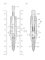
以下、本発明の実施の形態を図面に示すいくつかの実施例を参照して説明する。図1は、本発明の第一の構成に係るスパークプラグの一実施例を示す。該スパークプラグ100は、筒状の主体金具1、先端部21が突出するようにその主体金具1の内側に嵌め込まれた絶縁体2、先端に形成された発火部31を突出させた状態で絶縁体2の内側に設けられた中心電極3、及び主体金具1に一端が溶接等により結合されるとともに他端側が側方に曲げ返されて、その側面が中心電極3の先端部と対向するように配置された接地電極4等を備えている。また、接地電極4には上記発火部31に対向する発火部32が形成されており、それら発火部31と、対向する発火部32との間の隙間が火花放電ギャップgとされている。
Hereinafter, embodiments of the present invention will be described with reference to some examples shown in the drawings. FIG. 1 shows an embodiment of a spark plug according to the first configuration of the present invention. The
主体金具1は、低炭素鋼等の金属により円筒状に形成されており、スパークプラグ100のハウジングを構成するとともに、その外周面には、プラグ100を図示しないエンジンブロックに取り付けるためのねじ部7が形成されている。なお、1eは、主体金具1を取り付ける際に、スパナやレンチ等の工具を係合させる工具係合部であり、六角状の軸断面形状を有している。
The
また、絶縁体2の軸方向には貫通孔6が形成されており、その一方の端部側に端子金具13が固定され、同じく他方の端部側に中心電極3が固定されている。また、該貫通孔6内において端子金具13と中心電極3との間に抵抗体15が配置されている。この抵抗体15の両端部は、導電性ガラスシール層16,17を介して中心電極3と端子金具13とにそれぞれ電気的に接続されている。これら抵抗体15と導電性ガラスシール層16,17とが焼結導電材料部を構成している。なお、抵抗体15は、ガラス粉末と導電材料粉末(及び必要に応じてガラス以外のセラミック粉末)との混合粉末を原料とし、後述のガラスシール工程においてこれを加熱・プレスすることにより得られる抵抗体組成物で構成される。なお、抵抗体15を省略して、一層の導電性ガラスシール層により端子金具13と中心電極3とを一体化した構成としてもよい。
A through
絶縁体2は、内部に自身の軸方向に沿って中心電極3を嵌め込むための貫通孔6を有し、全体が以下の絶縁材料により構成されている。すなわち、該絶縁材料はアルミナを主体に構成され、Al成分を、Al2O3に換算した値にて85〜98mol%(望ましくは90〜98mol%)含有するアルミナ系セラミック焼結体として構成される。
The
Al以外の成分の具体的な組成としては下記のようなものを例示できる。
Si成分:SiO2換算値で1.50〜5.00mol%;Ca成分:CaO換算値で1.20〜4.00mol%;Mg成分:MgO換算値で0.05〜0.17mol%;Ba成分:BaO換算値で0.15〜0.50mol%;B成分:B2O3換算値で0.15〜0.50mol%。
The following can be illustrated as a specific composition of components other than Al.
Si component: 1.50~5.00mol% in terms of SiO 2 values; Ca component: 1.20~4.00mol% in terms of CaO value; Mg component: 0.05~0.17mol% in terms of MgO value; Ba component: 0.15~0.50mol% in terms of BaO value; B component: 0.15~0.50mol% in terms of B 2 O 3 value.
絶縁体2の軸方向中間には、周方向外向きに突出する突出部2eが例えばフランジ状に形成されている。そして、絶縁体2には、中心電極3(図1)の先端に向かう側を前方側として、該突出部2eよりも後方側がこれよりも細径に形成された本体部2bとされている。一方、突出部2eの前方側にはこれよりも細径の第一軸部2gと、その第一軸部2gよりもさらに細径の第二軸部2iがこの順序で形成されている。なお、本体部2bの外周面後端部にはコルゲーション部2cが形成されている。また、第一軸部2gの外周面は略円筒状とされ、第二軸部2iの外周面は先端に向かうほど縮径する略円錐面状とされている。
In the middle of the
他方、中心電極3の軸断面径は抵抗体15の軸断面径よりも小さく設定されている。そして、絶縁体2の貫通孔6は、中心電極3を挿通させる略円筒状の第一部分6aと、その第一部分6aの後方側(図面上方側)においてこれよりも大径に形成される略円筒状の第二部分6bとを有する。端子金具13と抵抗体15とは第二部分6b内に収容され、中心電極3は第一部分6a内に挿通される。中心電極3の後端部には、その外周面から外向きに突出して電極固定用凸部3cが形成されている。そして、上記貫通孔6の第一部分6aと第二部分6bとは、図3(a)の第一軸部2g内において互いに接続しており、その接続位置には、中心電極3の電極固定用凸部3cを受けるための凸部受け面6cがテーパ面あるいはアール面状に形成されている。
On the other hand, the axial sectional diameter of the
また、第一軸部2gと第二軸部2iとの接続部2hの外周面は段付面とされ、これが主体金具1の内面に形成された主体金具側係合部としての凸条部1cとリング状の板パッキン63を介して係合することにより、軸方向の抜止めがなされている。他方、主体金具1の後方側開口部内面と、絶縁体2の外面との間には、フランジ状の突出部2eの後方側周縁と係合するリング状の線パッキン62が配置され、そのさらに後方側にはタルク等の充填層61を介してリング状の線パッキン60が配置されている。そして、絶縁体2を主体金具1に向けて前方側に押し込み、その状態で主体金具1の開口縁をパッキン60に向けて内側に加締めることにより加締め部1dが形成され、主体金具1が絶縁体2に対して固定されている。
Moreover, the outer peripheral surface of the
図3(a)及び図3(b)は絶縁体2のいくつかの例を示すものである。その各部の寸法を以下に例示する。
・全長L1:30〜75mm。
・第一軸部2gの長さL2:0〜30mm(ただし、突出部2eとの接続部2fを含まず、第二軸部2iとの接続部2hを含む)。
・第二軸部2iの長さL3:2〜27mm。
・本体部2bの外径D1:9〜13mm。
・突出部2eの外径D2:11〜16mm。
・第一軸部2gの外径D3:5〜11mm。
・第二軸部2iの基端部外径D4:3〜8mm。
・第二軸部2iの先端部外径D5(ただし、先端面外周縁にアールないし面取りが施される場合は、中心軸線Oを含む断面において、該アール部ないし面取部の基端位置における外径を指す):2.5〜7mm。
・貫通孔6の第二部分6bの内径D6:2〜5mm。
・貫通孔6の第一部分6aの内径D7:1〜3.5mm。
・第一軸部2gの肉厚t1:0.5〜4.5mm。
・第二軸部2iの基端部肉厚t2(中心軸線Oと直交する向きにおける値):0.3〜3.5mm。
・第二軸部2iの先端部肉厚t3(中心軸線Oと直交する向きにおける値;ただし、先端面外周縁にアールないし面取りが施される場合は、中心軸線Oを含む断面において、該アール部ないし面取部の基端位置における肉厚を指す):0.2〜3mm。
・第二軸部2iの平均肉厚tA(=(t2+t3)/2):0.25〜3.25mm。
FIG. 3A and FIG. 3B show some examples of the
-Total length L1: 30-75 mm.
The length L2 of the
-Length L3 of the second shaft portion 2i: 2 to 27 mm.
-Outer diameter D1 of the
-Outer diameter D2 of the protruding
-Outer diameter D3 of the
-The base end outer diameter D4 of the second shaft portion 2i: 3 to 8 mm.
The outer diameter D5 of the distal end portion of the second shaft portion 2i (however, when the outer peripheral edge of the distal end surface is rounded or chamfered, in the cross section including the central axis O, at the proximal end position of the rounded portion or chamfered portion Refers to the outer diameter): 2.5-7 mm.
-Inner diameter D6 of the
The inner diameter D7 of the first portion 6a of the through
-Thickness t1 of the
-Base end portion thickness t2 of second shaft portion 2i (value in a direction orthogonal to central axis O): 0.3 to 3.5 mm.
The tip thickness t3 of the second shaft portion 2i (value in a direction orthogonal to the center axis O; however, when the outer peripheral edge of the tip surface is rounded or chamfered, The thickness at the base end position of the part or chamfered part): 0.2 to 3 mm.
-Average wall thickness tA (= (t2 + t3) / 2) of the second shaft portion 2i: 0.25 to 3.25 mm.
また、図1において、絶縁体2の主体金具1の後方側に突出している部分2kの長さLQは、23〜27mm(例えば25mm程度)である。さらに、絶縁体2の中心軸線Oを含む縦断面を取ったときに、絶縁体2の突出部分2kの外周面において、主体金具1の後端縁に対応する位置から、コルゲーション2cを経て絶縁体2の後端縁に至るまでの、その断面外形線に沿って測った長さLPは26〜32mm(例えば29mm程度)である。
In FIG. 1, the length LQ of the portion 2k protruding to the rear side of the
なお、図3(a)に示す絶縁体2における上記各部寸法は、例えば以下の通りである:L1=約60mm、L2=約10mm、L3=約14mm、D1=約11mm、D2=約13mm、D3=約7.3mm、D4=5.3mm、D5=4.3mm、D6=3.9mm、D7=2.6mm、t1=3.3mm、t2=1.4mm、t3=0.9mm、tA=1.15mm。
The above-described dimensions of the
また、図3(b)に示す絶縁体2は、第一軸部2g及び第二軸部2iがそれぞれ、図3(a)に示すものと比較してやや大きい外径を有している。各部の寸法は、例えば以下の通りである:L1=約60mm、L2=約10mm、L3=約14mm、D1=約11mm、D2=約13mm、D3=約9.2mm、D4=6.9mm、D5=5.1mm、D6=3.9mm、D7=2.7mm、t1=3.3mm、t2=2.1mm、t3=1.2mm、tA=1.65mm。
Further, in the
次に、図2に示すように、絶縁体2の表面、具体的にはコルゲーション部2cを含む本体部2bの外周面に釉薬層2dが形成されている。釉薬層2dの形成厚さは7〜150μm、望ましくは10〜50μmとされる。なお、図1に示すように、本体部2bに形成された釉薬層2dは、その軸方向前方側が主体金具1の内側に所定長入り込む形で形成される一方、後方側は本体部2bの後端縁位置まで延びている。
Next, as shown in FIG. 2, the
次に、釉薬層2dは、課題を解決するための手段及び作用・効果の欄にて説明した本発明の少なくともいずれかの組成を有するものである。各成分の組成範囲の臨界的意味については、既に詳細に説明済みであるからここでは繰り返さない。また、絶縁体本体部2bの基端部(主体金具1から後方に突出している部分の、コルゲーション部2cが付与されていない円筒状の外周面を呈する部分)外周面における釉薬層2dの厚さt1(平均値)は7〜50μmである。コルゲーション部2cは省略することもでき、この場合は、主体金具1の後端縁を基点として本体部1bの突出長さLQの50%までの部分の外周面における釉薬層2dの厚さ(平均値)をt1とみなす。
Next, the
次に、接地電極4及び中心電極3の本体部3aはNi合金等で構成されている。また、中心電極3の本体部3aの内部には、放熱促進のためにCuあるいはCu合金等で構成された芯材3bが埋設されている。一方、上記発火部31及び対向する発火部32は、Ir、Pt及びRhの1種又は2種以上を主成分とする貴金属合金を主体に構成される。中心電極3の本体部3aは先端側が縮径されるとともにその先端面が平坦に構成され、ここに上記発火部を構成する合金組成からなる円板状のチップを重ね合わせ、さらにその接合面外縁部に沿ってレーザ溶接、電子ビーム溶接、抵抗溶接等により溶接部Wを形成してこれを固着することにより発火部31が形成される。また、対向する発火部32は、発火部31に対応する位置において接地電極4にチップを位置合わせし、その接合面外縁部に沿って同様に溶接部Wを形成してこれを固着することにより形成される。なお、これらチップは、例えば表記組成となるように各合金成分を配合・溶解することにより得られる溶解材、又は合金粉末あるいは所定比率で配合された金属単体成分粉末を成形・焼結することにより得られる焼結材により構成することができる。なお、発火部31及び対向する発火部32は少なくとも一方を省略する構成としてもよい。
Next, the main body 3a of the
上記スパークプラグ100は、例えば下記のような方法で製造される。まず、絶縁体2であるが、これは原料粉末として、アルミナ粉末と、Si成分、Ca成分、Mg成分、Ba成分及びB成分の各成分源粉末を、焼成後に酸化物換算にて前述の組成となる所定の比率で配合し、所定量の結合剤(例えばPVA)と水とを添加・混合して成形用素地スラリーを作る。なお、各成分源粉末は、例えばSi成分はSiO2粉末、Ca成分はCaCO3粉末、Mg成分はMgO粉末、Ba成分がBaCO3あるいはBaSO4、B成分がH3BO3粉末の形で配合できる。なお、H3BO3は溶液の形で配合してもよい。
The
成形用素地スラリーは、スプレードライ法等により噴霧乾燥されて成形用素地造粒物とされる。そして、成形用素地造粒物をラバープレス成形することにより、絶縁体の原形となるプレス成形体を作る。成形体は、さらに外面側をグラインダ切削等により加工して、図1の絶縁体2に対応した外形形状に仕上げられ、次いで温度1400〜1600℃で焼成されて絶縁体2となる。
The forming substrate slurry is spray-dried by a spray drying method or the like to form a forming substrate granulated product. And the press molding body used as the original form of an insulator is made by carrying out the rubber press molding of the base granule for a shaping | molding. The molded body is further processed by grinder cutting or the like on the outer surface side to finish the outer shape corresponding to the
他方、釉薬スラリーの調製を以下のようにして行なう。
まず、Si、B、Zn、Ba、及びアルカリ金属成分(Na、K、Li)等の各成分源となる成分源粉末(例えば、Si成分はSiO2粉末、B成分はH3BO3粉末、ZnはZnO粉末、Ba成分はBaCO3あるいはBaSO4粉末、NaはNa2CO3粉末、KはK2CO3粉末、LiはLi2CO3粉末)を、所定の組成が得られるように配合して混合する。次いで、その混合物を1000〜1500℃に加熱して溶融させ、その溶融物を水中に投じて急冷・ガラス化し、さらに粉砕することにより釉薬粉末を作る。そして、この釉薬粉末にカオリン、蛙目粘土等の粘土鉱物と有機バインダとを適量配合し、さらに水を加えて混合することにより釉薬スラリーを得る。
On the other hand, the glaze slurry is prepared as follows.
First, component source powders serving as component sources such as Si, B, Zn, Ba, and alkali metal components (Na, K, Li) (for example, Si component is SiO 2 powder, B component is H 3 BO 3 powder, Zn is ZnO powder, Ba component is BaCO 3 or BaSO 4 powder, Na is Na 2 CO 3 powder, K is K 2 CO 3 powder, Li is Li 2 CO 3 powder) so as to obtain a predetermined composition And mix. Next, the mixture is heated to 1000 to 1500 ° C. to melt, and the melt is poured into water to quench and vitrify, and further pulverized to make a glaze powder. And a glaze slurry is obtained by mix | blending an appropriate quantity with clay minerals, such as a kaolin and a clam clay, and an organic binder, and adding water and mixing with this glaze powder.
そして、図5に示すように、この釉薬スラリーSを噴霧ノズルNから絶縁体2の必要な表面に噴霧・塗布することにより、釉薬粉末堆積層としての釉薬スラリー塗布層2d’を形成し、これを乾燥する。
Then, as shown in FIG. 5, the glaze slurry S is sprayed and applied from the spray nozzle N onto the required surface of the
次に、この釉薬スラリー塗布層2d’を形成した絶縁体2への、中心電極3と端子金具13との組付け、及び抵抗体15と導電性ガラスシール層16,17との形成工程の概略は以下の通りである。まず、図6(a)に示すように、絶縁体2の貫通孔6に対し、その第一部分6aに中心電極3を挿入した後、(b)に示すように導電性ガラス粉末Hを充填する。そして、(c)に示すように、貫通孔6内に押さえ棒28を挿入して充填した粉末Hを予備圧縮し、第一の導電性ガラス粉末層26を形成する。次いで抵抗体組成物の原料粉末を充填して同様に予備圧縮し、さらに導電性ガラス粉末を充填して予備圧縮を行なうことにより、図6(d)に示すように、中心電極3側(下側)から貫通孔6内には、第一の導電性ガラス粉末層26、抵抗体組成物粉末層25及び第二の導電性ガラス粉末層27が積層された状態となる。
Next, an outline of the process of assembling the
そして、図7(a)に示すように、貫通孔6に端子金具13を上方から配置した組立体PAを形成する。この状態で加熱炉に挿入してガラス軟化点以上である800〜950℃の所定温度に加熱し、その後、端子金具13を貫通孔6内へ中心電極3と反対側から軸方向に圧入して積層状態の各層25〜27を軸方向にプレスする。これにより、同図(b)に示すように、各層は圧縮・焼結されてそれぞれ導電性ガラスシール層16、抵抗体15及び導電性ガラスシール層17となる(以上、ガラスシール工程)。
Then, as shown in FIG. 7A, an assembly PA in which the terminal fitting 13 is disposed in the through
ここで、釉薬スラリー塗布層2d’に含まれる釉薬粉末の軟化点を600〜700℃としておけば、図7に示すように、釉薬スラリー塗布層2d’を、上記ガラスシール工程における加熱により同時に釉焼して釉薬層2dとすることができる。また、ガラスシール工程の加熱温度として800〜950℃の比較的低い温度を採用することで、中心電極3や端子金具13の表面への酸化も生じにくくなる。
Here, if the softening point of the glaze powder contained in the glaze
なお、加熱炉(釉焼炉も兼ねる)としてバーナー式のガス炉を用いると、加熱雰囲気には燃焼生成物である水蒸気が比較的多く含まれる。このとき、釉薬組成としてB成分の含有量を40mol%以下に留めたものを使用することにより、そのような水蒸気が多く存在する雰囲気下においても、釉焼時の流動性が確保できて、しかも平滑で均質であり、かつ絶縁性も良好な釉薬層形成が可能となる。 When a burner type gas furnace is used as a heating furnace (also serving as a smoldering furnace), the heating atmosphere contains a relatively large amount of water vapor as a combustion product. At this time, by using a glaze composition in which the content of the B component is kept at 40 mol% or less, the fluidity at the time of calcination can be secured even in an atmosphere where a lot of water vapor exists. It is possible to form a glaze layer that is smooth and homogeneous and also has good insulating properties.
こうしてガラスシール工程が完了した組立体PAには、主体金具1や接地電極4等が組み付けられて、図1に示すスパークプラグ100が完成する。スパークプラグ100は、そのねじ部7においてエンジンブロックに取り付けられ、燃焼室に供給される混合気への着火源として使用される。ここで、スパークプラグ100への高圧ケーブルあるいはイグニッションコイルの装着は、図1に仮想線で示すように、絶縁体2の本体部2bの外周面を覆うゴムキャップ(例えばシリコンゴム等で構成される)RCを用いて行われる。このゴムキャップRCの孔径は、本体部2bの外径D1(図3)よりも0.5〜1.0mm程度小さいものが使用される。本体部2bは孔を弾性的に拡径しつつその基端部まで覆われるようにこれに押し込まれる。その結果、ゴムキャップRCは、孔内面において本体部2bの基端部外周面に密着し、フラッシュオーバ等を防止するための絶縁被覆として機能する。
The
なお、本発明のスパークプラグは図1に示すタイプのものに限らず、接地電極の先端を中心電極の側面と対向させてそれらの間に火花ギャップを形成したものであってもよい。また、スパークプラグを、絶縁体の先端部を中心電極の側面と接地電極の先端面との間に進入させたセミ沿面放電型スパークプラグとして構成してもよい。 Note that the spark plug of the present invention is not limited to the type shown in FIG. 1, and may be one in which the tip of the ground electrode is opposed to the side surface of the center electrode and a spark gap is formed therebetween. Further, the spark plug may be configured as a semi-surface discharge type spark plug in which the tip of the insulator is inserted between the side surface of the center electrode and the tip surface of the ground electrode.
本発明の効果を確認するために、以下の実験を行なった。
絶縁体2を次のようにして作製した。まず、原料粉末として、アルミナ粉末(アルミナ95mol%、Na含有量(Na2O換算値)0.1mol%、平均粒径3.0μm)に対し、SiO2(純度99.5%、平均粒径1.5μm)、CaCO3(純度99.9%、平均粒径2.0μm)、MgO(純度99.5%、平均粒径2μm)、BaCO3(純度99.5%、平均粒径1.5μm)、H3BO3(純度99.0%、平均粒径1.5μm)、ZnO(純度99.5%、平均粒径2.0μm)を所定比率にて配合するとともに、この配合した粉末総量を100質量部として、親水性バインダとしてのPVAを3質量部と、水103質量部とを加えて湿式混合することにより、成形用素地スラリーを作製した。
In order to confirm the effect of the present invention, the following experiment was conducted.
The
次いで、これら組成の異なるスラリーをそれぞれスプレードライ法により乾燥して、球状の成形用素地造粒物を調製した。なお、造粒物は、ふるいにより粒径50〜100μmに整粒している。そして、この造粒物を、公知のラバープレス法により圧力50MPaにて成形し、その成形体の外周面にグラインダ研削を施して所定の絶縁体形状に加工するとともに、温度1550℃で焼成することにより絶縁体2を得た。なお、蛍光X線分析により、絶縁体2は下記の組成を有していることがわかった:Al成分:Al2O3換算値で94.9mol%;Si成分:SiO2換算値で2.4mol%;Ca成分:CaO換算値で1.9mol%;Mg成分:MgOに換算値で0.1mol%;Ba成分:BaOに換算値で0.4mol%;B成分:B2O3換算値で0.3mol%。
Subsequently, the slurry having different compositions was dried by a spray drying method to prepare a spherical molding base granulated product. In addition, the granulated product is sized by a sieve to a particle size of 50 to 100 μm. Then, this granulated product is molded at a pressure of 50 MPa by a known rubber press method, and the outer peripheral surface of the molded product is processed into a predetermined insulator shape by grinding, and fired at a temperature of 1550 ° C. Thus, an
また、図3(a)を援用して示す絶縁体2の各部寸法は以下の通りである:L1=約60mm、L2=約8mm、L3=約14mm、D1=約10mm、D2=約13mm、D3=約7mm、D4=5.5mm、D5=4.5mm、D6=4mm、D7=2.6mm、t1=1.5mm、t2=1.45mm、t3=1.25mm、tA=1.35mm。さらに、図1を援用して示すと、絶縁体2の主体金具1の後方側に突出している部分2kの長さLQは25mmであり、絶縁体2の中心軸線Oを含む縦断面を取ったときに、絶縁体2の突出部分2kの外周面において、主体金具1の後端縁に対応する位置から、コルゲーション2cを経て絶縁体2の後端縁に至るまでの、その段面外形線に沿って測った長さLPは29mmである。
Further, the dimensions of each part of the
次に、釉薬スラリーを次のようにして調製した。まず、原料としてSiO2(純度99.5%)、Al2O3粉末(純度99.5%)、H3BO3粉末(純度98.5%)、Na2CO3粉末(純度99.5%)、K2CO3粉末(純度99%)、Li2CO3粉末(純度99%)、SrCO3粉末(純度99%)、BaSO4粉末(純度99.5%)、ZnO粉末(純度99.5%)、MoО3粉末(純度99%)、Fe2O3粉末(純度99%)、WО3粉末(純度99%)、Ni3O4粉末(純度99%)、MnO2粉末(純度99%)、CaO粉末(純度99.5%)、ZrO2粉末(純度99.5%)、TiO2粉末(純度99.5%)、HfO2粉末(純度99%)、MgO粉末(純度99.5%)、Bi2O3粉末(純度99%)、SnO2粉末(純度99.5%)、Sb2O5粉末(純度99%)、P2O5粉末(純度99%)、CuO粉末(純度99%)、CeO2粉末(純度99%)、Cr2O3粉末(純度99.5%)、Sb2O5粉末(純度99%)を各種比率で配合し、その混合物を1000〜1500℃に加熱して溶融させ、その溶融物を水中に投じて急冷・ガラス化し、さらにアルミナ製ポットミルにより粒径50μm以下に粉砕することにより釉薬粉末を作製した。そして、この釉薬粉末100質量部に対し粘土鉱物としてのニュージーランドカオリンを3質量部、及び有機バインダとしてのPVAを2質量部配合し、さらに水を100質量部加えて混合することにより釉薬スラリーを得た。
Next, the glaze slurry was prepared as follows. First, SiO 2 (purity 99.5%), Al 2 O 3 powder (purity 99.5%), H 3 BO 3 powder (purity 98.5%), Na 2 CO 3 powder (purity 99.5) as raw materials. %),
この釉薬スラリーを、図5のように噴霧ノズルより絶縁体2の表面に噴霧後、乾燥して釉薬スラリー塗布層2d’を形成した。なお、乾燥後の釉薬の塗布厚さは100μm程度である。この絶縁体2を用いて、図1に示すスパークプラグ100を各種作成した。ただし、ねじ部7の外径は14mmとした。また、抵抗体15の原料粉末としてはB2O3−SiO2−BaO−Li2O系ガラス、ZrO2粉末、カーボンブラック粉末、TiO2粉末、金属Al粉末を、導電性ガラスシール層16,17の原料粉末としてはB2O3−SiO2−Na2O系ガラス、Cu粉末、Fe粉末、Fe−B粉末をそれぞれ用い、ガラスシール時の加熱温度、すなわち釉焼温度は900℃にて行った。
The glaze slurry was sprayed on the surface of the
他方、粉砕せずに塊状に凝固させた釉薬試料も作製した。なお、この塊状の釉薬試料は、X線回折によりガラス化(非晶質化)したものであることを確認した。これを用いて下記の実験を行った。
[1]化学組成分析:蛍光X線分析による。各試料の分析値(酸化物換算した値による)を表1〜表5に示している。なお、絶縁体2の表面に形成された釉薬層2dの各組成をEPMA法により測定したが、該塊状試料を用いて測定した分析値とほぼ一致していることが確認できた。
[2]熱膨張係数:塊状試料から寸法5mm×5mm×10mmの測定試料を切り出し、公知のディラトメータ法により20℃から350℃までの平均値として測定している。また、絶縁体2からも上記寸法の測定試料を切り出し、同様の測定を行ったところ、その値は73×10−7/℃であった。
[3]軟化点:粉末試料50mgを加熱しながら示差熱分析を行い、室温より測定開始し、第2番目の吸熱ピークとなった温度を軟化点として測定した。なお、この温度は、釉薬の粘度が4.5×10⁷ポアズに到達する温度に相当する。
On the other hand, a glaze sample coagulated in a lump without being crushed was also prepared. In addition, it was confirmed that this bulk glaze sample was vitrified (amorphized) by X-ray diffraction. The following experiment was conducted using this.
[1] Chemical composition analysis: by fluorescent X-ray analysis. Tables 1 to 5 show the analysis values (according to oxide-converted values) of the respective samples. In addition, although each composition of the
[2] Thermal expansion coefficient: A measurement sample having a size of 5 mm × 5 mm × 10 mm was cut out from a block sample and measured as an average value from 20 ° C. to 350 ° C. by a known dilatometer method. Moreover, when the measurement sample of the said dimension was cut out also from the
[3] Softening point: Differential thermal analysis was performed while heating 50 mg of the powder sample, measurement was started from room temperature, and the temperature at which the second endothermic peak was obtained was measured as the softening point. This temperature corresponds to a temperature at which the viscosity of the glaze reaches 4.5 × 10 7 poise.
また、各スパークプラグについては、500℃での絶縁抵抗測定を、図4を用いて既に説明した方法により通電電圧1000Vにて行った。また、絶縁体2に対する釉薬層2dの形成状態を目視にて観察するとともに、絶縁体の基端部外周面位置における釉薬層の膜厚を断面のSEM観察により測定した。
Moreover, about each spark plug, the insulation resistance measurement in 500 degreeC was performed by the energizing
さらに、各試験品に対して以下のような衝撃試験を行った。すなわち、図8に示すように、各スパークプラグ100の取付ねじ部7を試験品固定台203のねじ孔203aにねじ込み、絶縁体2の本体部2bが上向きに突出するように固定する。そして、その本体部2bのさらに上方において、絶縁体2の中心軸線O上に位置する軸支点202に対し、先端に鋼製のハンマー200を取り付けたアーム201を旋回可能に取り付ける。なお、アーム201の長さは330mm、ハンマー200の重量は1.13kgであり、絶縁体2の後方側本体部2bに降り下ろしたときのハンマー位置が、絶縁体2の後端面からの鉛直方向距離にして1mm(コルゲーション2cの第一山位置に対応しているとなるように)、軸支点202の位置が定められている。そして、アーム201の中心軸線Oからの旋回角度が所定値となるようにハンマー200を持ち上げて、後方側本体部2bに向けて自由落下により降り下ろす操作を、角度間隔2゜にて徐々に大きくしながら繰り返し、絶縁体に割れが生ずる衝撃耐久角度値θを求めた。以上の結果を表1〜表5に示す。
Further, the following impact test was performed on each test product. That is, as shown in FIG. 8, the mounting

この結果によると、前記した本発明に係る釉薬組成を選択することにより、Pbをほとんど含有しないにもかかわらず、比較的低温で釉焼可能であり、また、十分な絶縁性能が確保されていることがわかる。また、釉焼面の外観もおおむね良好である。さらに、衝撃耐久角度値も35゜以上の良好な値に確保でき、釉薬層付き絶縁体の耐衝撃性を向上できていることがわかる。 According to this result, by selecting the glaze composition according to the present invention described above, it is possible to sinter at a relatively low temperature despite the fact that Pb is hardly contained, and sufficient insulation performance is ensured. I understand that. In addition, the appearance of the glazed surface is generally good. Furthermore, it can be seen that the impact durability angle value can be secured to a good value of 35 ° or more, and the impact resistance of the insulator with the glaze layer can be improved.
1 主体金具
2 絶縁体
2d 釉薬層
2d’ 釉薬スラリー塗布層(釉薬粉末堆積層)
3 中心電極
4 接地電極
S 釉薬スラリー
1
3
Claims (14)
Pb成分の含有量がPbO換算にて1mol%以下とされ、
Si成分をSiO2に酸化物換算した値にて15〜60mol%、B成分をB2O3に酸化物換算した値にて22〜50mol%、Zn成分をZnOに酸化物換算した値にて10〜30mol%、Ba及び/又はSr成分を、BaOないしSrOに酸化物換算した値にて合計で0.5〜35mol%含有し、
F成分の含有量が1mol%以下であり、
Al成分をAl2O3に酸化物換算した値にて0.1〜5mol%含有し、
アルカリ金属成分として、NaはNa2O、KはK2O、LiはLi2Oに酸化物換算した値にて、Liを必須とする1種又は2種以上を合計で1.1〜10mol%の範囲にて含有し、
かつ、Li成分の含有量範囲がLi2Oに酸化物換算した値にて1.1〜6mol%とされたことを特徴とするスパークプラグ。 In the spark plug in which an insulator made of alumina ceramic is disposed between the center electrode and the metal shell, an oxide-based glaze layer is formed so as to cover at least part of the surface of the insulator, and the glaze layer is ,
The content of the Pb component is 1 mol% or less in terms of PbO,
The Si component is converted to SiO 2 in an oxide conversion value of 15 to 60 mol%, the B component is converted into an oxide conversion value into B 2 O 3 , and the Zn component is converted into an oxide conversion value into ZnO. 10 to 30 mol%, Ba and / or Sr components are contained in a total of 0.5 to 35 mol% in terms of oxide conversion to BaO or SrO,
The content of the F component is 1 mol% or less,
The Al component contained 0.1 to 5 mol% in terms of oxide values to Al 2 O 3,
As an alkali metal component, Na is Na 2 O, K is K 2 O, Li is a value in terms of oxide converted to Li 2 O, and a total of 1.1 to 10 mol of one or two or more essential components of Li. % In the range,
And a spark plug, characterized in that the range of content of Li component is a 1.1~6Mol% in terms of oxide value to Li 2 O.
該軸線方向において前記中心電極の先端に向かう側を前方側として、前記突出部に対し後方側に隣接する絶縁体本体部の基端部外周面が円筒面状に形成され、
その基端部外周面を覆う形で前記釉薬層が膜厚7〜50μmの範囲内にて形成されている請求項1ないし9のいずれか1項に記載のスパークプラグ。 In the insulator, a circumferential protrusion is formed on the outer peripheral surface at an axially intermediate position,
In the axial direction, the side toward the tip of the center electrode is the front side, and the outer peripheral surface of the base end portion of the insulator main body adjacent to the rear side with respect to the protruding portion is formed in a cylindrical shape,
The spark plug according to any one of claims 1 to 9, wherein the glaze layer is formed in a thickness range of 7 to 50 µm so as to cover an outer peripheral surface of the base end portion.
前記アームの前記中心軸線からの旋回角度が所定値となるようにハンマーを持ち上げて、前記絶縁体後方部に向けて自由落下により降り下ろす操作を、角度2゜間隔で段階的に大きくしながら繰り返したときの、絶縁体に割れが生ずるときの限界角度として求められる衝撃耐久角度値が35゜以上である請求項1ないし10のいずれか1項に記載のスパークプラグ。 While the direction away from the spark discharge gap in the axial direction of the insulator is the rear direction, the metal shell is fixed to the test article fixing base so that the insulator rear portion protruding from the metal shell is vertically upward, Further above the insulator rear part, a 330 mm long arm having a 1.13 kg steel hammer attached to the tip is pivotably attached to a shaft fulcrum located on the central axis of the insulator. The position of the shaft fulcrum is determined so that the hammer position when lowered to the rear part of the insulator is 1 mm as a vertical distance from the rear end surface of the insulator,
The operation of lifting the hammer so that the turning angle of the arm from the central axis becomes a predetermined value and lowering the hammer toward the rear part of the insulator by free fall is repeated while increasing stepwise at intervals of 2 °. The spark plug according to any one of claims 1 to 10, wherein an impact durability angle value obtained as a limit angle when a crack occurs in the insulator is 35 ° or more.
前記中心電極と一体に、又は導電性結合層を間に挟んで前記中心電極と別体に設けられた軸状の端子金具部を備え、
かつ該スパークプラグ全体を約500℃に保持し、前記絶縁体を介して前記端子金具部と前記主体金具との間で通電することにより測定される絶縁抵抗値が200MΩ以上である請求項1ないし11のいずれか1項に記載のスパークプラグ。 In the through hole of the insulator, the spark plug is
An axial terminal fitting provided integrally with the center electrode or separately from the center electrode with a conductive coupling layer interposed therebetween,
The insulation resistance value measured by holding the entire spark plug at about 500 ° C. and energizing the terminal metal part and the metal shell through the insulator is 200 MΩ or more. 11. The spark plug according to any one of 11 above.
前記釉薬層は、20〜350℃の温度範囲における前記釉薬層の平均の熱膨張係数が、50×10−7/℃〜85×10−7/℃である請求項1ないし12のいずれか1項に記載のスパークプラグ。 The insulator is constituted by alumina insulating material containing 85~98Mol% by weight was in terms of oxide of Al component to the Al 2 O 3,
The glaze layer has an average thermal expansion coefficient of 50 × 10 −7 / ° C. to 85 × 10 −7 / ° C. in the temperature range of 20 to 350 ° C. 13. The spark plug according to item.
The spark plug according to any one of claims 1 to 13, wherein a softening point of the glaze layer is 600 to 700 ° C.
Priority Applications (1)
| Application Number | Priority Date | Filing Date | Title |
|---|---|---|---|
| JP2006116130A JP2006196474A (en) | 2000-06-30 | 2006-04-19 | Spark plug |
Applications Claiming Priority (2)
| Application Number | Priority Date | Filing Date | Title |
|---|---|---|---|
| JP2000197770 | 2000-06-30 | ||
| JP2006116130A JP2006196474A (en) | 2000-06-30 | 2006-04-19 | Spark plug |
Related Parent Applications (1)
| Application Number | Title | Priority Date | Filing Date |
|---|---|---|---|
| JP2001197669A Division JP2002117955A (en) | 2000-06-30 | 2001-06-29 | Spark plug |
Publications (2)
| Publication Number | Publication Date |
|---|---|
| JP2006196474A true JP2006196474A (en) | 2006-07-27 |
| JP2006196474A5 JP2006196474A5 (en) | 2008-02-14 |
Family
ID=36802343
Family Applications (1)
| Application Number | Title | Priority Date | Filing Date |
|---|---|---|---|
| JP2006116130A Pending JP2006196474A (en) | 2000-06-30 | 2006-04-19 | Spark plug |
Country Status (1)
| Country | Link |
|---|---|
| JP (1) | JP2006196474A (en) |
Cited By (2)
| Publication number | Priority date | Publication date | Assignee | Title |
|---|---|---|---|---|
| WO2009133683A1 (en) * | 2008-04-28 | 2009-11-05 | 日本特殊陶業株式会社 | Spark plug |
| WO2011036832A1 (en) * | 2009-09-25 | 2011-03-31 | 日本特殊陶業株式会社 | Spark plug and process for producing spark plug |
-
2006
- 2006-04-19 JP JP2006116130A patent/JP2006196474A/en active Pending
Cited By (5)
| Publication number | Priority date | Publication date | Assignee | Title |
|---|---|---|---|---|
| WO2009133683A1 (en) * | 2008-04-28 | 2009-11-05 | 日本特殊陶業株式会社 | Spark plug |
| JP5238803B2 (en) * | 2008-04-28 | 2013-07-17 | 日本特殊陶業株式会社 | Spark plug |
| WO2011036832A1 (en) * | 2009-09-25 | 2011-03-31 | 日本特殊陶業株式会社 | Spark plug and process for producing spark plug |
| JP2011070928A (en) * | 2009-09-25 | 2011-04-07 | Ngk Spark Plug Co Ltd | Spark plug, and process for producing spark plug |
| US8564184B2 (en) | 2009-09-25 | 2013-10-22 | Ngk Spark Plug Co., Ltd. | Spark plug and process for producing spark plug |
Similar Documents
| Publication | Publication Date | Title |
|---|---|---|
| EP1130728B1 (en) | Spark plug | |
| KR100584943B1 (en) | Spark plug | |
| KR100642349B1 (en) | Spark plug | |
| JP2000048931A (en) | Spark plug and its manufacture | |
| JP3690995B2 (en) | Spark plug | |
| EP1168546B1 (en) | Spark plug | |
| JP2002175863A (en) | Spark plug | |
| JP3511602B2 (en) | Spark plug | |
| JP3632953B2 (en) | Spark plug | |
| JP2002056950A (en) | Spark plug | |
| JP2006196474A (en) | Spark plug | |
| JP3510172B2 (en) | Spark plug | |
| JP2002117955A (en) | Spark plug | |
| JP4833526B2 (en) | Spark plug | |
| JP2007042656A (en) | Spark plug and its manufacturing method |
Legal Events
| Date | Code | Title | Description |
|---|---|---|---|
| A621 | Written request for application examination |
Free format text: JAPANESE INTERMEDIATE CODE: A621 Effective date: 20070914 |
|
| A521 | Written amendment |
Free format text: JAPANESE INTERMEDIATE CODE: A523 Effective date: 20071225 |
|
| A131 | Notification of reasons for refusal |
Free format text: JAPANESE INTERMEDIATE CODE: A131 Effective date: 20080317 |
|
| A521 | Written amendment |
Free format text: JAPANESE INTERMEDIATE CODE: A523 Effective date: 20080429 |
|
| A131 | Notification of reasons for refusal |
Free format text: JAPANESE INTERMEDIATE CODE: A131 Effective date: 20080718 |
|
| A521 | Written amendment |
Free format text: JAPANESE INTERMEDIATE CODE: A523 Effective date: 20080908 |
|
| A02 | Decision of refusal |
Free format text: JAPANESE INTERMEDIATE CODE: A02 Effective date: 20081212 |