JP2006192032A - Transdermal blood gas sensor - Google Patents
Transdermal blood gas sensor Download PDFInfo
- Publication number
- JP2006192032A JP2006192032A JP2005005714A JP2005005714A JP2006192032A JP 2006192032 A JP2006192032 A JP 2006192032A JP 2005005714 A JP2005005714 A JP 2005005714A JP 2005005714 A JP2005005714 A JP 2005005714A JP 2006192032 A JP2006192032 A JP 2006192032A
- Authority
- JP
- Japan
- Prior art keywords
- electrode
- sensor
- gas
- silver
- permeable membrane
- Prior art date
- Legal status (The legal status is an assumption and is not a legal conclusion. Google has not performed a legal analysis and makes no representation as to the accuracy of the status listed.)
- Granted
Links
Images


Abstract
Description
本発明は、血中の酸素分圧や二酸化炭素分圧などを皮膚の表面から計測する経皮血中ガスセンサと、同センサ用の電極ユニットに関するものである。特に、電極材料の使用量を低減し、小型化と低コスト化を実現できる経皮血中ガスセンサに関するものである。 The present invention relates to a percutaneous blood gas sensor for measuring oxygen partial pressure, carbon dioxide partial pressure, etc. in blood from the surface of the skin, and an electrode unit for the sensor. In particular, the present invention relates to a transdermal blood gas sensor that can reduce the amount of electrode material used and achieve downsizing and cost reduction.
新生児や人工呼吸を必要とする重症患者の呼吸管理のために、血中の酸素分圧や二酸化炭素分圧を計測する技術として、例えば特許文献1に記載のセンサが知られている。このセンサは、センサの外部のガス分圧に比例した量のガスがセンサのメンブレンを通じて電解液中に溶け込み、この溶存ガス量が各測定電極に生じる電流値や電位に相関することを利用してガス分圧を計測するセンサである。 For example, a sensor described in Patent Document 1 is known as a technique for measuring oxygen partial pressure or carbon dioxide partial pressure in blood for respiratory management of neonates or critically ill patients who require artificial respiration. This sensor utilizes the fact that an amount of gas proportional to the gas partial pressure outside the sensor dissolves in the electrolyte solution through the sensor membrane, and the amount of dissolved gas correlates with the current value and potential generated at each measurement electrode. It is a sensor that measures the gas partial pressure.
図4に示すように、このセンサ200は、センサ本体210、メンブレンホルダ220およびリング状カラー230から構成されている。センサ本体210は、その内部に、O2計測用陰極211、CO2計測用pH電極212、ヒータ213およびサーミスタ214を有し、これら各部材は銀製電極215に保持されている。銀製電極215は、O2計測用陽極、CO2計測用比較電極、加熱体を兼ねており、計測側表面を塩化銀で覆われている。この加熱体である銀製電極215はヒータ213により加熱され、サーミスタ214で銀製電極215の温度を測定して、その測定結果に基づいてヒータ213への通電量が制御されることで温度調整される。さらに、センサ本体210内には、pH電極212の計測信号を増幅するアンプ216も内蔵されている。
As shown in FIG. 4, the
一方、メンブレンホルダ220はリング状カラー230とセンサ本体210の間に位置し、リング状カラー230がセンサ本体210にねじ込まれることにより、センサ本体210に取付けられる。また、メンブレンホルダ220とリング状カラー230の間には計測対象ガスを透過するメンブレン240が挟み込まれ、センサ本体210の下面とメンブレン240との間に電解液250が保持される。
On the other hand, the
このセンサで、例えば血中の酸素分圧を計測する場合、ヒータ213で銀製電極215を所定の温度に加熱して、メンブレン240を皮膚に接触させる。ヒータ213のからの熱により温められた皮下組織内の酸素は皮膚表面より拡散してメンブレン240を透過し、電解液250中に溶存される。そして、例えば陰極-陽極間に一定の電圧をかけると、溶存酸素量に応じた電流が流れるため、この電流を計測することで血中の酸素濃度を求めることができ、その酸素濃度から酸素分圧を計測することができる。
For example, when the oxygen partial pressure in blood is measured with this sensor, the
しかし、上記のセンサでは、次のような問題があった。 However, the above sensor has the following problems.
(1)電極材料を多用しなければならない。
上記の説明から明らかなように、O2計測用陽極、CO2計測用比較電極、加熱体を兼ねている銀製電極はブロック状の比較的大きなもので、高価な銀を多用しなければならず、その結果、製品コストの増大を招いている。
(1) A lot of electrode materials must be used.
As is clear from the above explanation, the anode for O 2 measurement, the reference electrode for CO 2 measurement, and the silver electrode that also serves as a heating element are relatively large blocks, and expensive silver must be used frequently. As a result, the product cost is increased.
(2)電解液やメンブレンの交換作業が煩雑である。
電解液とメンブレンは定期的に交換が必要であるが、上記のセンサではリング状カラーを外し、メンブレンを交換すると共に、電解液の充填も行わなければならない。特に、計測感度が不安定とならないように、メンブレンを不均一な張力とならないように装着したり、一定量の電解液を正確に充填し、メンブレンとセンサ本体との間の間隔が均一になるように交換作業を行うことは必ずしも容易ではない。
(2) The replacement work of the electrolyte and membrane is complicated.
The electrolyte solution and the membrane need to be replaced regularly. However, in the above sensor, the ring collar is removed, the membrane must be replaced, and the electrolyte solution must be filled. Especially, in order to prevent unstable measurement sensitivity, the membrane should be mounted so as not to have a non-uniform tension, or a certain amount of electrolyte should be filled accurately, and the distance between the membrane and the sensor body should be uniform. Thus, it is not always easy to perform the replacement work.
(3)電極の定期的なメンテナンスが必要である。
上述した従来のセンサでは、その性能を良好に保つためには、各電極を定期的にメンテナンスしなければならない。具体的には、O2電極では電極反応により陽極(金または白金)に徐々に付着する銀を研磨して除去する必要がある。また、CO2電極では、銀表面の塩化銀がはがれやすいため、その塩化銀を再度被覆処理する必要がある。
(3) Periodic electrode maintenance is required.
In the conventional sensor described above, each electrode must be regularly maintained in order to keep its performance good. Specifically, in the O 2 electrode, it is necessary to polish and remove silver that gradually adheres to the anode (gold or platinum) by an electrode reaction. In addition, since the silver chloride on the silver surface is easily peeled off at the CO 2 electrode, it is necessary to coat the silver chloride again.
本発明は、上記の事情に鑑みてなされたもので、その主目的は、電極材料の使用量を低減できる経皮血中ガスセンサを提供することにある。 The present invention has been made in view of the above circumstances, and its main object is to provide a transdermal blood gas sensor capable of reducing the amount of electrode material used.
本発明の他の目的は、電極ユニットの交換が容易で、電極のメンテナンスが不要な経皮血中ガスセンサを提供することにある。 Another object of the present invention is to provide a transcutaneous blood gas sensor in which an electrode unit can be easily replaced and no electrode maintenance is required.
さらに、本発明の別の目的は、計測対象ガスの濃度を電気信号として計測できる電極機能を持った電極ユニットを提供することにある。 Furthermore, another object of the present invention is to provide an electrode unit having an electrode function capable of measuring the concentration of the measurement target gas as an electric signal.
本発明は、計測対象ガスの透過膜と不透過部材との間に電解液を保持した薄型のユニットを用い、そのユニットに電極機能を持たせることで上記の目的を達成する。 The present invention achieves the above object by using a thin unit holding an electrolytic solution between a permeable membrane for a gas to be measured and a non-permeable member and providing the unit with an electrode function.
本発明経皮血中ガスセンサは、センサ本体と、センサ本体に装着される電極ユニットとを有する。そして、この電極ユニットは、計測対象ガスの透過膜と、同ガスの不透過部材と、この透過膜および不透過部材の間に保持される電解液と、電解液中の計測対象ガスの濃度を電気信号として計測可能な薄膜状の一方電極および他方電極とを有することを特徴とする。 The transdermal blood gas sensor of the present invention has a sensor body and an electrode unit attached to the sensor body. The electrode unit is configured to measure the concentration of the measurement target gas in the electrolyte, the permeable membrane of the measurement target gas, the non-permeable member of the same gas, the electrolytic solution held between the permeable membrane and the non-permeable member. It has the thin film-like one electrode and other electrode which can be measured as an electric signal.
また、本発明電極ユニットは、計測対象ガスの透過膜と、同ガスの不透過部材と、この透過膜および不透過部材の間に保持される電解液と、電解液中の計測対象ガスの濃度を電気信号として計測可能な薄膜状の一方電極および他方電極とを有することを特徴とする。 In addition, the electrode unit of the present invention includes a permeable membrane of a measurement target gas, a non-permeable member of the same gas, an electrolytic solution held between the permeable membrane and the non-permeable member, and a concentration of the measurement target gas in the electrolytic solution. It has the thin film-like one electrode and other electrode which can be measured as an electric signal.
本発明センサは、計測対象ガスの透過膜と不透過部材との間に電解液を保持させると共に、この透過膜と不透過部材との間に電極機能を付加することで、薄膜状の電極を利用することができ、高価な電極材料の使用量を低減することができる。 The sensor of the present invention holds the electrolyte solution between the permeable membrane of the gas to be measured and the non-permeable member, and adds an electrode function between the permeable membrane and the non-permeable member, so that the thin-film electrode is formed. It can be used, and the amount of expensive electrode material used can be reduced.
また、計測対象ガスの透過膜や電解液の交換は、電極ユニットごとセンサ本体から着脱するだけで極めて容易に行える。 In addition, the permeable membrane of the measurement target gas and the electrolyte solution can be replaced very easily by simply attaching and detaching the electrode unit together with the sensor body.
以下、本発明をより詳しく説明する。 Hereinafter, the present invention will be described in more detail.
本発明センサは、センサ本体と、電極ユニットとを有する。まず、本発明の主たる特徴である電極ユニットの構成から説明する。 The sensor of the present invention has a sensor body and an electrode unit. First, the structure of the electrode unit, which is the main feature of the present invention, will be described.
(電極ユニット)
電極ユニットは、電解液を保持すると共に、電解液内の計測ガス濃度を電気信号として抽出可能な電極機能を具えている。
(Electrode unit)
The electrode unit has an electrode function capable of holding the electrolytic solution and extracting the measurement gas concentration in the electrolytic solution as an electrical signal.
<透過膜>
透過膜は、計測対象ガスが透過可能な膜であり、計測対象ガスの種類に応じて適宜選択すれば良い。例えば、O2やCO2の透過膜としてフッ素樹脂やポリプロピレンフィルムが挙げられる。
<Permeation membrane>
The permeable membrane is a membrane through which the measurement target gas can pass, and may be appropriately selected according to the type of the measurement target gas. For example, a fluororesin or a polypropylene film can be used as the O 2 or CO 2 permeable membrane.
<不透過部材>
不透過部材は、透過膜との間に電解液と電極を保持して、電極ユニットにおける透過膜と反対側から計測対象ガスが電解液に侵入することや電解液の蒸発を防止して、計測精度の向上に寄与する機能を有する。例えば、O2やCO2の不透過部材として高密度ポリエステル、セラミックス、ガラスエポキシなどが挙げられる。この不透過膜部材の形態としては、代表的にはフィルムが挙げられる。ただし、柔軟性に乏しい樹脂片やセラミックス片などでもセンサ本体よりの熱伝導を阻害しない限りある程度厚みのある板状でも許容される。通常、不透過部材はセンサ本体側に面して設けられる。
<Impermeable member>
The impervious member holds the electrolyte and electrode between the permeable membrane, and prevents measurement target gas from entering the electrolyte from the opposite side of the permeable membrane in the electrode unit and prevents evaporation of the electrolyte. It has a function that contributes to improving accuracy. For example, high-density polyester, ceramics, glass epoxy and the like can be used as O 2 and CO 2 impermeable members. A typical example of the form of the impermeable membrane member is a film. However, even a resin piece or a ceramic piece with poor flexibility may be allowed to have a plate shape with a certain thickness as long as the heat conduction from the sensor body is not hindered. Usually, the impervious member is provided facing the sensor body side.
<電解液>
電解液は、計測対象のガスが溶存でき、そのガスの溶存量に応じて電極反応が可能な液体であればよい。より具体的には、O2ではKClやNaCl、CO2ではNaHCO3を主成分とする液体などを好適に利用することができる。
<Electrolyte>
The electrolyte solution may be any liquid that can dissolve the gas to be measured and can undergo an electrode reaction according to the dissolved amount of the gas. More specifically, a liquid mainly composed of KCl or NaCl for O 2 and NaHCO 3 as a main component for CO 2 can be preferably used.
この電解液は透過膜と不透過部材との間のほぼ全面にわたって存在する必要はなく、少なくとも後述する一方電極と他方電極の電極反応が生じる箇所に電解液が存在していればよい。 This electrolytic solution does not need to exist over almost the entire surface between the permeable membrane and the non-permeable member, and it is sufficient that the electrolytic solution exists at least at a location where an electrode reaction between one electrode and the other electrode described later occurs.
<一方電極と他方電極>
一方電極と他方電極は、計測対象ガスの電解液中の溶存量に応じて、電気信号を取り出すことが可能な電極対であれば良い。本発明では、透過膜と不透過部材との間に一方電極と他方電極を配置するため、これら電極は薄膜状のものとする。
<One electrode and the other electrode>
The one electrode and the other electrode may be an electrode pair that can extract an electrical signal in accordance with the dissolved amount of the measurement target gas in the electrolyte. In the present invention, since one electrode and the other electrode are disposed between the permeable membrane and the non-permeable member, these electrodes are in the form of a thin film.
より具体的な材質としては、計測対象ガスがO2の場合、計測性能の観点から、一方電極を白金または金からなる陰極とし、他方電極を銀または銀と塩化銀の複合材料からなる陽極とすることが好適である。その場合、両電極間に所定の電圧をかけておくと、陰極では酸素の還元反応が、陽極では銀の酸化反応がそれぞれ行われ、両電極間に電界電流が流れ、その電流を測定することにより電解液中の酸素濃度を近似的に測定することができる。銀と塩化銀の複合材料の代表例としては、塩化銀を被覆した銀が挙げられる。 More specifically, when the measurement target gas is O 2 , from the viewpoint of measurement performance, one electrode is a cathode made of platinum or gold, and the other electrode is an anode made of silver or a composite material of silver and silver chloride; It is preferable to do. In that case, if a predetermined voltage is applied between both electrodes, an oxygen reduction reaction is performed at the cathode and a silver oxidation reaction is performed at the anode, and an electric field current flows between both electrodes, and the current is measured. Thus, the oxygen concentration in the electrolytic solution can be approximately measured. A typical example of a composite material of silver and silver chloride is silver coated with silver chloride.
計測対象ガスがCO2の場合、計測性能の観点から、一方電極をイオン選択性電極で、他方電極を塩化銀または銀と塩化銀の複合材料からなる比較電極とすることが好適である。イオン選択性電極は、電解液中に存在する特定イオンの濃度に応答して、電極電位が変化する電極である。このイオン選択性電極を比較電極と併用することにより、特定イオンの濃度を測定する。CO2の濃度は、透過膜を通って電解液にCO2が溶け込み、炭酸となってpH(水素イオン濃度)が変化することを利用して測定される。より具体的には、イオン選択性電極と増幅用のアンプとして電界効果型トランジスタ(FET)とを一体化したISFET(Ion Sensitive Field Effect Transistor)が好適に利用できる。銀と塩化銀の複合材料の代表例としては、塩化銀を被覆した銀が挙げられる。 When the measurement target gas is CO 2 , it is preferable from the viewpoint of measurement performance that one electrode is an ion selective electrode and the other electrode is a comparative electrode made of silver chloride or a composite material of silver and silver chloride. An ion selective electrode is an electrode whose electrode potential changes in response to the concentration of specific ions present in the electrolyte. By using this ion selective electrode in combination with a comparative electrode, the concentration of specific ions is measured. The concentration of CO 2 is passed through a permeable membrane CO 2 dissolves in the electrolyte, pH becomes carbonate (hydrogen ion concentration) is measured by utilizing the change. More specifically, an ISFET (Ion Sensitive Field Effect Transistor) in which an ion selective electrode and a field effect transistor (FET) are integrated as an amplifier for amplification can be suitably used. A typical example of a composite material of silver and silver chloride is silver coated with silver chloride.
また、一つのセンサで複数の血中ガス濃度を計測できるよう、一つの電極ユニットに複数種の電極対を配置してもよい。その場合、例えば、一つの電極ユニットにO2計測用の電極対とCO2計測用の電極対が配されることになる。特に、O2計測用の陽極とCO2計測用の比較電極は、共通する材質が利用できるため、これら陽極と比較電極は一体のものを共用することが部品点数と使用材料削減の観点から好適である。 In addition, a plurality of types of electrode pairs may be arranged in one electrode unit so that a plurality of blood gas concentrations can be measured with one sensor. In this case, for example, an electrode pair for measuring O 2 and an electrode pair for measuring CO 2 are arranged in one electrode unit. In particular, since the same material can be used for the anode for measuring O 2 and the reference electrode for measuring CO 2 , it is preferable from the viewpoint of reducing the number of parts and materials used that these anode and reference electrode are shared. It is.
なお、これらの一方電極および他方電極は、透過膜側に接着形成しても良いし、不透過部材側に接着形成してもいずれでも良い。 The one electrode and the other electrode may be formed on the permeable membrane side or may be formed on the non-permeable member side.
<信号端子>
その他、通常、上記電極からの電気信号をセンサ本体側に伝送するための信号端子が設けられる。例えば、上記各電極からの信号を伝送する導体パターンを透過膜と不透過部材の間に形成し、この導体パターンから電極ユニットの外に導電部材を引き出して信号端子とすれば良い。その場合、この信号端子自体が電極ユニットをセンサ本体に装着するための係合部とすることが好適である。
<Signal terminal>
In addition, a signal terminal for transmitting an electrical signal from the electrode to the sensor body is usually provided. For example, a conductor pattern for transmitting signals from the electrodes may be formed between the permeable membrane and the non-permeable member, and the conductive member may be drawn out of the electrode unit from the conductor pattern to be a signal terminal. In this case, it is preferable that the signal terminal itself is an engaging portion for mounting the electrode unit on the sensor body.
もちろん、電極ユニットをセンサ本体に装着するための係合部を信号端子とは別に形成しても構わない。例えば、電極ユニットの外周部を覆う補強リング部を設け、この補強リング部のセンサ本体のハウジングに係合する係合部を信号端子とは別に形成しても良い。その場合、後述する固定リングの使用を省略することも可能である。 Of course, an engaging portion for mounting the electrode unit on the sensor body may be formed separately from the signal terminal. For example, a reinforcing ring portion that covers the outer peripheral portion of the electrode unit may be provided, and an engaging portion that engages with the housing of the sensor main body of the reinforcing ring portion may be formed separately from the signal terminal. In that case, it is possible to omit the use of a fixing ring described later.
(センサ本体)
一方、センサ本体の基本構成は、従来からの経皮血中ガスセンサの構成が利用できる。代表的には、センサ本体は、ハウジングと、加熱手段と、加熱体と、温度センサとを具えている。
(Sensor body)
On the other hand, the basic configuration of the sensor body can use the conventional configuration of a transdermal blood gas sensor. Typically, the sensor main body includes a housing, a heating unit, a heating body, and a temperature sensor.
<ハウジング>
ハウジングは、本発明センサのカバーに相当する部材である。通常、樹脂成形された開口部を有する容器状の部材が好適に利用できる。このハウジングには、上記電極ユニットの信号端子が差し込まれるレセプタクルを有することが望ましい。信号端子をレセプタクルに係合させ、本発明センサの計測信号をセンサ本体を介して経皮血中ガス測定装置に出力できるようにする。そして、このハウジング内には加熱手段と、加熱体と、温度センサが収納される。
<Housing>
The housing is a member corresponding to the cover of the sensor of the present invention. Usually, a container-like member having a resin-molded opening can be suitably used. The housing preferably has a receptacle into which the signal terminal of the electrode unit is inserted. The signal terminal is engaged with the receptacle so that the measurement signal of the sensor of the present invention can be output to the percutaneous blood gas measurement device via the sensor body. And in this housing, a heating means, a heating body, and a temperature sensor are accommodated.
<加熱手段>
加熱手段は、次述する加熱体を所定温度に温め、その温度を皮膚に伝熱させて皮下組織からの計測対象ガスを効率的に皮膚表面に拡散させるためのものである。例えば、通電加熱によるヒータが好適に利用できる。
<Heating means>
The heating means warms a heating body described below to a predetermined temperature, transfers the temperature to the skin, and efficiently diffuses the measurement target gas from the subcutaneous tissue to the skin surface. For example, a heater by energization heating can be suitably used.
<加熱体>
上記の加熱手段により温められる部材が加熱体である。この加熱体の熱が電極ユニットを介して皮膚に伝達される。加熱体は、加熱手段で温められることに対する耐熱性と速やかに加熱手段の熱が伝達される熱伝導性を有する材料が好ましい。
<Heating body>
The member heated by the heating means is a heating body. The heat of the heating body is transmitted to the skin through the electrode unit. The heating body is preferably made of a material having heat resistance against being heated by the heating means and heat conductivity capable of quickly transferring the heat of the heating means.
従来、この加熱体がO2計測用陽極、CO2計測用比較電極の機能も兼ねていたため電極面を塩化銀で覆われた銀で構成されていたが、本発明においてはO2計測用電極対、CO2計測用電極対が電極ユニットに設けられているため、加熱体はより安価な材料を用いることが好ましい。より具体的には、銅、アルミニウム、洋白(洋銀:Cu・Ni・Znの合金)が挙げられる。 Conventionally, since this heating element also functions as an anode for O 2 measurement and a reference electrode for CO 2 measurement, the electrode surface was composed of silver covered with silver chloride. In the present invention, the electrode for O 2 measurement Since the CO 2 measurement electrode pair is provided in the electrode unit, it is preferable to use a cheaper material for the heating element. More specifically, copper, aluminum, and white (a silver: Cu / Ni / Zn alloy) can be used.
この加熱体は、通常、その一部がハウジングの開口部から露出するようにハウジング内にはめ込まれる。そして、この加熱体の露出面に面して電極ユニットが装着される。 This heating element is usually fitted in the housing such that a part thereof is exposed from the opening of the housing. Then, the electrode unit is mounted facing the exposed surface of the heating body.
<温度センサ>
加熱体の温度は、温度センサにより検知され、その検知結果に基づいて加熱手段を制御することで調整される。このための温度センサには、サーミスタなどの半導体素子が好適に利用できる。
<Temperature sensor>
The temperature of the heating body is detected by a temperature sensor and adjusted by controlling the heating means based on the detection result. A semiconductor element such as a thermistor can be suitably used for the temperature sensor for this purpose.
<増幅手段>
その他、必要に応じてセンサ本体内に増幅手段を設けてもよい。この増幅手段は、電極ユニットの電極から送られる信号を増幅して、経皮血中ガス測定装置に出力する。
<Amplification means>
In addition, amplification means may be provided in the sensor body as necessary. This amplification means amplifies the signal sent from the electrode of the electrode unit and outputs it to the transcutaneous blood gas measurement device.
(固定リング)
その他、センサ本体に係合されて、電極ユニットをセンサ本体側に固定する固定リングを利用することが好ましい。代表的には、センサ本体の外周にねじ込みにより装着可能で、電極ユニットの周縁部を覆う環状部材が挙げられる。
(Fixing ring)
In addition, it is preferable to use a fixing ring that is engaged with the sensor body and fixes the electrode unit to the sensor body side. Typically, an annular member that can be attached to the outer periphery of the sensor main body by screwing and covers the peripheral portion of the electrode unit is exemplified.
本発明センサおよび電極ユニットによれば、次の効果を奏することができる。 According to the sensor and the electrode unit of the present invention, the following effects can be obtained.
(1)計測対象ガスの透過膜と不透過部材との間に電解液を保持させると共に、透過膜と不透過部材との間に電極機能を付加することで、薄膜状の電極を利用することができる。そのため、高価な電極材料の使用量を低減することができ、製品コストを低減することもできる。 (1) Use a thin-film electrode by holding the electrolyte between the permeable membrane of the gas to be measured and the non-permeable member and adding an electrode function between the permeable membrane and the non-permeable member. Can do. Therefore, the amount of expensive electrode material used can be reduced, and the product cost can be reduced.
(2)計測対象ガスの透過膜や電解液の交換は、電極ユニットごとセンサ本体から着脱するだけで極めて容易に行える。そのため、従来問題となっていたメンブレンを均一な張力で装着することや、電解液層の厚みを均一にするといった煩雑な作業を解消することができる。 (2) Replacement of the permeable membrane or electrolyte for the gas to be measured can be performed very easily by simply attaching and detaching the electrode unit together with the sensor body. Therefore, it is possible to eliminate troublesome operations such as mounting a membrane that has been a problem in the past with uniform tension and making the thickness of the electrolyte layer uniform.
(3)電極は計測対象ガスの透過膜と不透過部材との間に挟みこまれて保護されているため、直接手で電極に触れることが無く、電極を汚損したり損傷させたりすることもない。 (3) Since the electrode is protected by being sandwiched between the permeable membrane of the gas to be measured and the impermeable member, the electrode is not directly touched by hand, and the electrode may be soiled or damaged. Absent.
(4)各電極は電極ユニットごと交換されるため、従来のように電極を研磨したり塩化銀を再被覆するなどのメンテナンスを行うことなく、センサの性能を良好な状態に保持することができる。 (4) Since each electrode is replaced for each electrode unit, the sensor performance can be maintained in a good state without performing maintenance such as polishing the electrode or recoating silver chloride as in the past. .
以下、本発明の実施の形態を説明する。ここでは、血中のO2とCO2の分圧を計測するためのセンサを例として説明する。 Embodiments of the present invention will be described below. Here, a sensor for measuring the partial pressure of O 2 and CO 2 in blood will be described as an example.
(全体構造)
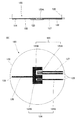
本発明センサ100は、図1および図2に示すように、センサ本体110、電極ユニット120および固定リング130を具えている。これらの各構成要素を詳細に説明する。
(Overall structure)
As shown in FIGS. 1 and 2, the
(センサ本体)
センサ本体110は、ハウジング111と、ヒータ112と、加熱体113と、サーミスタ114と増幅手段115とを具えている。
(Sensor body)
The
<ハウジング>
ハウジング111は、本発明センサ100のカバーに相当する部材で、その内部にヒータ112と、加熱体113と、サーミスタ114とを収納している。ここでは、上部が閉じられ、下部が開口した円盤容器状のプラスチック製ハウジング111を用いた。このハウジング111の開口側外周面には雄ネジ部111Aが形成され、そこに固定リング130がねじ込まれることで、センサ本体110と固定リング130との間に電極ユニット120を挟みこんで保持する。
<Housing>
The
また、このハウジング111には、開口側端面にレセプタクル111Bが形成されている。このレセプタクル111Bは、後述する電極ユニットの信号端子126が差し込まれ、後述する各電極対と電気的接続を行うためのものである。
In addition, the
<ヒータ>
加熱手段であるヒータ112は、次述する加熱体113を所定温度に温め、その温度を皮膚に伝熱させて皮下組織からの酸素や二酸化炭素を効率的に皮膚表面に拡散させるためのものである。ここでは、加熱体113の外周に電熱線を巻き付けてヒータ112としている。このヒータ112は、図示しない経皮血中ガス測定装置に接続されて、同装置より電力供給を受ける。
<Heater>
The
<加熱体>
上記のヒータ112により温められる部材が加熱体113である。この加熱体113の熱が電極ユニット120を介して皮膚に伝達される。ここでは、上部側ほど外径が大きく下方に向かうに従って段階的に径が小さくなる円柱ブロック状の銅製加熱体を用いている。また、この加熱体113の上面には、サーミスタ114の装着孔113Aが下方に向かって伸びるように形成されている。
<Heating body>
A member heated by the
この加熱体113は、その下面がハウジング111の開口から露出するようにハウジング111内にはめ込まれる。そして、この加熱体113の露出面に面して電極ユニット120が装着される。
The
<サーミスタ>
加熱体113の温度は、温度センサであるサーミスタ114により検知され、その検知結果に基づいてヒータ112を制御することで調整される。このサーミスタ114は、上記加熱体113の装着孔113A内に収納されている。このサーミスタ114は、図示しない経皮血中ガス測定装置に接続されている。
<Thermistor>
The temperature of the
<増幅手段>
ハウジング111と加熱体113上面との間に形成された空間には、増幅手段115が配置されている。この増幅手段115は、電極ユニット120の電極から送られる信号を増幅して、図示しない経皮血中ガス測定装置に出力する。
<Amplification means>
In the space formed between the
(電極ユニット)
次に電極ユニット120を説明する。図3(A)に電極ユニットの断面図を、同(B)にその平面図を示す。この電極ユニット120は、透過膜121、不透過部材122、電解液123、O2計測用電極対124、CO2計測用電極対125および信号端子126を有し、電解液123を両者121,122の間に保持すると共に、電解液内の計測ガス濃度を電気信号として抽出可能な電極機能を具えている。
(Electrode unit)
Next, the
<透過膜>
透過膜121は、計測対象ガスが透過可能な膜である。ここでは、O2およびCO2の透過膜としてポリプロピレンフィルムを用いた。この透過膜121は、図1に示すように下面側に配されて、直接皮膚と接触される。
<Permeation membrane>
The
<不透過部材>
不透過部材122は、透過膜121との間に電解液123と電極対124、125を保持して、電極ユニット120における透過膜121と反対側から計測対象ガスが電解液122に侵入することを防止する。ここでは、O2およびCO2の不透過部材122として高密度ポリエステルフィルムを用いた。この不透過部材122はセンサ本体110における加熱体113の露出面に面して設けられる。
<Impermeable member>
The
<電解液>
電解液123は、計測対象のガスが溶存でき、そのガスの溶存量に応じて電極反応が可能な液体である。ここではNaCl、NaHCO3などを主成分とする液体を用いている。また、この電解液123は、電極ユニット120の一部にのみ保持されている。本例では、次述するO2計測用電極対124とCO2計測用電極対125の電極反応に関わる箇所、つまり、電極ユニット120のほぼ中央部のみに電解液123を保持している。この電解液123の保持される箇所は、部分的に透過膜121と不透過部材122とが接着されない部分を形成し、その部分における透過膜121と不透過部材122との間に電解液123を貯留させることで構成している。その他、電解液123を保持するために、多孔質フィルムを用いてもよい。
<Electrolyte>
The
<O2計測用電極対とCO2計測用電極対>
本例では、O2とCO2の両方を一つのセンサで計測できるよう、O2計測用電極対とCO2計測用電極対を設けている。
<O 2 measurement electrode pair and CO 2 measurement electrode pair>
In this example, an O 2 measurement electrode pair and a CO 2 measurement electrode pair are provided so that both O 2 and CO 2 can be measured by one sensor.
O2計測用電極対124は、白金からなる陰極124Aと、表面が塩化銀で覆われた銀からなる陽極124Bとで構成される。陰極124Aと陽極124Bの間に所定の電圧をかけておくと、陰極124Aでは酸素の還元反応が、陽極124Bでは銀の酸化反応がそれぞれ行われ、両電極124A、124B間に電界電流が流れ、その電流を測定することにより電解液123中の酸素濃度を近似的に測定することができる。本例では、電極ユニット120のほぼ中央から外周側に伸びる細長い薄膜状の陰極124Aと、電極ユニット120のほぼ中央に配されてE型で陰極124Aよりも大きな陽極124Bを用いている。陰極124Aの先端は、E型の陽極124Bの2つある凹部の一つにはめ込まれるように配され、陽極124Bと一定のギャップが確保されている。
The O 2 measuring
CO2計測用電極対125は、ISFET(Ion Sensitive Field Effect Transistor)125Aを用いた一方電極と、表面が塩化銀で覆われた銀からなる比較電極125Bとで構成される。ISFET125Aはイオン選択性電極と増幅用のアンプとしてFETを一体化した半導体イオン電極である。このISFET125Aは、透過膜121を通ったCO2が電解液123に溶け込み炭酸となってpH(水素イオン濃度)が変化することを、比較電極125Bと併用することにより電極電位の変位として抽出してCO2濃度を計測する。このISFET125AはE型の比較電極125B(陽極124B)の2つある凹部の残る一つにはめ込まれるように比較電極125Bと一定のギャップをもって配され、電極ユニット120の外周側に伸びる2本の導電パターン127接続されている。この2本の導電パターン127はO2計測用の陰極124A平行に配されている。
The CO 2
上記のO2計測用の陽極124BとCO2計測用の比較電極125Bは、共通する材質で構成されるため、これら陽極124Bと比較電極125Bは一体のものとして共用している。この陽極124B(比較電極125B)には1本の細長い薄膜状の導電パターン128が接続されている。その導電パターン128は、電極ユニット120のほぼ中央部から陰極124Aおよび導電パターン127とは反対方向に伸びて外周縁部にまで達している。
The
<信号端子>
この電極ユニット120には、電極対124,125からの電気信号をセンサ本体側に伝送するための信号端子126が設けられる。本例では、O2計測用の陽極124Bの一端、ISFET125Aに接続される2本の導電パターン127の各端部、陽極124B(比較電極125B)に接続される導電パターン128の端部の合計4箇所に信号端子126を形成している。これら各端子126は、不透過部材122を貫通して、電極ユニットの不透過部材122(センサ本体110)側に突出されている。これらの端子126が前述したハウジング111のレセプタクル111Bにはめ込まれることで各電極対124,125からの電気信号がセンサ本体側に伝送される。
<Signal terminal>
The
(固定リング)
上記の電極ユニット120をセンサ本体110に装着する際、同電極ユニット120を確実にセンサ本体110に押圧するため、固定リング130が用いられる(図1、図2参照)。この固定リング130は、環状部131と、その下方において内周側に張り出した薄いリング状の押圧面132とから構成される。環状部131の内側には、ハウジングの雄ねじ部111Aにねじ込まれる雌ネジ部131Aが形成されている。
(Fixing ring)
When the
電極ユニット120をセンサ本体120に装着し、さらにハウジングの雄ネジ部111Aに固定リングの雌ネジ部131Aをねじ込むことで、電極ユニット120の周縁部は押圧面132でハウジング111との間に挟まれる。そして、ハウジング111開側外周端面よりも加熱体113の下面が下方に突出しているため、電極ユニット120は加熱体113の下面に押し付けられて一定の張力で張った状態に保持される。
By attaching the
(作用効果)
上記の本発明センサによれば、計測対象ガスの透過膜と不透過部材との間に電解液を保持させると共に、両膜の間に電極機能を付加することで、薄膜状の電極を利用することができ、高価な電極材料の使用量を低減することができる。
(Function and effect)
According to the above-described sensor of the present invention, the electrolyte solution is held between the permeable membrane of the measurement target gas and the non-permeable member, and the electrode function is added between the two membranes, thereby using the thin film electrode. The amount of expensive electrode material used can be reduced.
また、計測対象ガスの透過膜や電解液の交換は、固定リングを取り外し、電極ユニットごとセンサ本体から着脱するだけで極めて容易に行える。 In addition, the permeable membrane of the measurement target gas and the electrolytic solution can be exchanged very easily by simply removing the fixing ring and attaching / detaching the electrode unit together with the sensor body.
さらに、電極は計測対象ガスの透過膜と不透過部材との間に挟みこまれて保護されているため、直接手で電極に触れることが無く、電極を汚損したり損傷させたりすることもない。 Furthermore, since the electrode is sandwiched and protected between the permeable membrane of the measurement target gas and the non-permeable member, the electrode is not directly touched by hand, and the electrode is not soiled or damaged. .
そして、電極ユニットごと電極も交換されるため、従来、必要とされていた電極のメンテナンスも不要となる。 In addition, since the electrodes are exchanged together with the electrode units, the maintenance of the electrodes that has been conventionally required becomes unnecessary.
本発明センサおよび電極ユニットは、皮膚の上から血中の酸素分圧や二酸化炭素分圧を計測する分野に利用できる。より具体的には、新生児や人工呼吸を必要とする重症患者の呼吸管理などに好適に利用することができる。 The sensor and electrode unit of the present invention can be used in the field of measuring oxygen partial pressure and carbon dioxide partial pressure in blood from above the skin. More specifically, it can be suitably used for respiratory management of newborns and critically ill patients who require artificial respiration.
100 センサ
110 センサ本体
111 ハウジング 112 ヒータ 113 加熱体 114 サーミスタ
115 増幅手段 111A 雄ネジ部 111B レセプタクル 113A 装着孔
120 電極ユニット
121 透過膜 122 不透過部材 123 電解液 124 O2計測用電極対
125 CO2計測用電極対 124A 陰極 124B 陽極 125A ISFET
125B 比較電極 126 信号端子 127、128 導電パターン
130 固定リング
131 環状部 132 押圧面 131A 雌ネジ部
200 センサ
210 センサ本体 220 メンブレンホルダ 230 リング状カラー
240 メンブレン 250 電解液
211 O2計測用陰極 212 CO2計測用pH電極 213 ヒータ
214 サーミスタ 215 銀製電極 216 アンプ
100 sensors
110 Sensor body
115 Amplifying means
120 electrode unit
121
125 CO 2 electrode pair 124A
130 Retaining ring
131
200 sensors
210
240
211 Cathode for O 2 measurement 212 pH electrode for CO 2 measurement 213 Heater
214 Thermistor 215
Claims (6)
センサ本体に装着される電極ユニットとを有し、
この電極ユニットは、
計測対象ガスの透過膜と、
同ガスの不透過部材と、
前記透過膜および不透過部材の間に保持される電解液と、
電解液中の計測対象ガスの濃度を電気信号として計測可能な薄膜状の一方電極および他方電極とを有することを特徴とする経皮血中ガスセンサ。 A sensor body;
An electrode unit mounted on the sensor body,
This electrode unit
A permeable membrane for the gas to be measured;
An impermeable member of the same gas;
An electrolyte solution held between the permeable membrane and the impermeable member;
A transcutaneous blood gas sensor comprising a thin film-like one electrode and the other electrode capable of measuring the concentration of a measurement target gas in an electrolyte as an electrical signal.
O2計測用の一方電極が白金または金からなる陰極で、他方電極が銀または銀と塩化銀の複合材料からなる陽極であり、
CO2計測用の一方電極がイオン選択性電極で、他方電極が塩化銀または銀と塩化銀の複合材料からなる比較電極であることを特徴とする請求項1に記載の経皮血中ガスセンサ。 The gas to be measured is O 2 and CO 2
One electrode for O 2 measurement is a cathode made of platinum or gold, and the other electrode is an anode made of silver or a composite material of silver and silver chloride,
The transdermal blood gas sensor according to claim 1, wherein one electrode for measuring CO 2 is an ion selective electrode, and the other electrode is a comparative electrode made of silver chloride or a composite material of silver and silver chloride.
同ガスの不透過部材と、
前記透過膜と不透過部材との間に保持される電解液と、
電解液中の計測対象ガスの濃度を電気信号として計測可能な薄膜状の一方電極および他方電極とを有することを特徴とする経皮血中ガスセンサ用の電極ユニット。 A permeable membrane for the gas to be measured;
An impermeable member of the same gas;
An electrolyte solution held between the permeable membrane and the impermeable member;
An electrode unit for a transdermal blood gas sensor, comprising a thin film-like one electrode and the other electrode capable of measuring the concentration of a measurement target gas in an electrolyte as an electrical signal.
Priority Applications (1)
| Application Number | Priority Date | Filing Date | Title |
|---|---|---|---|
| JP2005005714A JP4699766B2 (en) | 2005-01-12 | 2005-01-12 | Transdermal blood gas sensor |
Applications Claiming Priority (1)
| Application Number | Priority Date | Filing Date | Title |
|---|---|---|---|
| JP2005005714A JP4699766B2 (en) | 2005-01-12 | 2005-01-12 | Transdermal blood gas sensor |
Publications (2)
| Publication Number | Publication Date |
|---|---|
| JP2006192032A true JP2006192032A (en) | 2006-07-27 |
| JP4699766B2 JP4699766B2 (en) | 2011-06-15 |
Family
ID=36798555
Family Applications (1)
| Application Number | Title | Priority Date | Filing Date |
|---|---|---|---|
| JP2005005714A Expired - Fee Related JP4699766B2 (en) | 2005-01-12 | 2005-01-12 | Transdermal blood gas sensor |
Country Status (1)
| Country | Link |
|---|---|
| JP (1) | JP4699766B2 (en) |
Cited By (2)
| Publication number | Priority date | Publication date | Assignee | Title |
|---|---|---|---|---|
| JP2021113764A (en) * | 2020-01-20 | 2021-08-05 | 国立大学法人東海国立大学機構 | Hydrogen sensor and computation device |
| WO2023007799A1 (en) * | 2021-07-28 | 2023-02-02 | 株式会社堀場アドバンスドテクノ | Ion electrode, water-quality measurement device, membrane part, and ion-electrode manufacturing method |
Citations (5)
| Publication number | Priority date | Publication date | Assignee | Title |
|---|---|---|---|---|
| JPS5657437A (en) * | 1979-07-23 | 1981-05-19 | Brattle Res & Dev Ass | Measuring device for concentration of gas in blood |
| JPS5944246A (en) * | 1982-07-30 | 1984-03-12 | バイオスペシフイック・テクノロジ−ズ インコ−ポレ−テッド | Subcataneous blood gas sensor of solid state |
| JPS61115538A (en) * | 1984-11-10 | 1986-06-03 | 株式会社日立製作所 | Subcataneous sensor |
| JP2002537634A (en) * | 1999-02-25 | 2002-11-05 | メドトロニック ミニメド インコーポレイテッド | Test plug and cable for glucose monitor |
| JP2003325460A (en) * | 2002-05-16 | 2003-11-18 | Ntt Docomo Kansai Inc | Adapter for transmitting biological information |
-
2005
- 2005-01-12 JP JP2005005714A patent/JP4699766B2/en not_active Expired - Fee Related
Patent Citations (5)
| Publication number | Priority date | Publication date | Assignee | Title |
|---|---|---|---|---|
| JPS5657437A (en) * | 1979-07-23 | 1981-05-19 | Brattle Res & Dev Ass | Measuring device for concentration of gas in blood |
| JPS5944246A (en) * | 1982-07-30 | 1984-03-12 | バイオスペシフイック・テクノロジ−ズ インコ−ポレ−テッド | Subcataneous blood gas sensor of solid state |
| JPS61115538A (en) * | 1984-11-10 | 1986-06-03 | 株式会社日立製作所 | Subcataneous sensor |
| JP2002537634A (en) * | 1999-02-25 | 2002-11-05 | メドトロニック ミニメド インコーポレイテッド | Test plug and cable for glucose monitor |
| JP2003325460A (en) * | 2002-05-16 | 2003-11-18 | Ntt Docomo Kansai Inc | Adapter for transmitting biological information |
Cited By (3)
| Publication number | Priority date | Publication date | Assignee | Title |
|---|---|---|---|---|
| JP2021113764A (en) * | 2020-01-20 | 2021-08-05 | 国立大学法人東海国立大学機構 | Hydrogen sensor and computation device |
| JP7457317B2 (en) | 2020-01-20 | 2024-03-28 | 国立大学法人東海国立大学機構 | hydrogen sensor |
| WO2023007799A1 (en) * | 2021-07-28 | 2023-02-02 | 株式会社堀場アドバンスドテクノ | Ion electrode, water-quality measurement device, membrane part, and ion-electrode manufacturing method |
Also Published As
| Publication number | Publication date |
|---|---|
| JP4699766B2 (en) | 2011-06-15 |
Similar Documents
| Publication | Publication Date | Title |
|---|---|---|
| US4197853A (en) | PO2 /PCO2 sensor | |
| US5338435A (en) | Integrated circuit hydrated sensor apparatus | |
| USRE31440E (en) | Electrochemical electrode with heating means | |
| CA1142227A (en) | Temperature compensation for disposable electrochemical sensors | |
| JP2726755B2 (en) | Sensor assembly device for analytical quality and ▲ pH ▼ measurement | |
| US4265250A (en) | Electrode | |
| US20170160228A1 (en) | Potentiometric sensor | |
| JPH02232554A (en) | Sensor construction | |
| JPH07507955A (en) | Sensor for non-invasive in-vivo determination of analytes and blood flow | |
| JPH057657B2 (en) | ||
| US4685465A (en) | Electrode device for transcutaneously measuring a blood gas parameter and for sensing a bioelectrical signal and an electrode assembly comprising such an electrode device | |
| CN103299181A (en) | Method and apparatus for measuring oxidation-reduction potential | |
| JPH0237768B2 (en) | ||
| JP2014081348A (en) | Electrochemical gas sensor and mounting structure of the same | |
| JP4699766B2 (en) | Transdermal blood gas sensor | |
| JP4529140B2 (en) | Water vapor sensor | |
| US4333473A (en) | Apparatus for the cutaneous determination of the oxygen partial pressure in blood | |
| JP2002048756A (en) | Electrochemical gas sensor | |
| US20020042686A1 (en) | Residual chlorine meter and residual chlorine measuring method | |
| JP2009216523A (en) | Galvanic cell type sensor | |
| US8496795B2 (en) | Electrochemical gas sensor with at least one punctiform measuring electrode | |
| JP2000009681A (en) | Constant potential electrolysis gas sensor | |
| JPH0230256B2 (en) | ||
| JPH0328368Y2 (en) | ||
| JPS62122634A (en) | Sensor for percutaneous measurement of concentration of oxygen in blood |
Legal Events
| Date | Code | Title | Description |
|---|---|---|---|
| A711 | Notification of change in applicant |
Free format text: JAPANESE INTERMEDIATE CODE: A712 Effective date: 20061221 |
|
| A621 | Written request for application examination |
Free format text: JAPANESE INTERMEDIATE CODE: A621 Effective date: 20071227 |
|
| A711 | Notification of change in applicant |
Free format text: JAPANESE INTERMEDIATE CODE: A711 Effective date: 20071227 |
|
| A521 | Written amendment |
Free format text: JAPANESE INTERMEDIATE CODE: A821 Effective date: 20071227 |
|
| A977 | Report on retrieval |
Free format text: JAPANESE INTERMEDIATE CODE: A971007 Effective date: 20100824 |
|
| A131 | Notification of reasons for refusal |
Free format text: JAPANESE INTERMEDIATE CODE: A131 Effective date: 20100830 |
|
| A521 | Written amendment |
Free format text: JAPANESE INTERMEDIATE CODE: A523 Effective date: 20101029 |
|
| A131 | Notification of reasons for refusal |
Free format text: JAPANESE INTERMEDIATE CODE: A131 Effective date: 20101210 |
|
| A521 | Written amendment |
Free format text: JAPANESE INTERMEDIATE CODE: A523 Effective date: 20110207 |
|
| TRDD | Decision of grant or rejection written | ||
| A01 | Written decision to grant a patent or to grant a registration (utility model) |
Free format text: JAPANESE INTERMEDIATE CODE: A01 Effective date: 20110228 |
|
| A61 | First payment of annual fees (during grant procedure) |
Free format text: JAPANESE INTERMEDIATE CODE: A61 Effective date: 20110303 |
|
| R150 | Certificate of patent or registration of utility model |
Ref document number: 4699766 Country of ref document: JP Free format text: JAPANESE INTERMEDIATE CODE: R150 |
|
| R250 | Receipt of annual fees |
Free format text: JAPANESE INTERMEDIATE CODE: R250 |
|
| R250 | Receipt of annual fees |
Free format text: JAPANESE INTERMEDIATE CODE: R250 |
|
| LAPS | Cancellation because of no payment of annual fees |