JP2006191574A - Slot coupled patch antenna - Google Patents
Slot coupled patch antenna Download PDFInfo
- Publication number
- JP2006191574A JP2006191574A JP2005368572A JP2005368572A JP2006191574A JP 2006191574 A JP2006191574 A JP 2006191574A JP 2005368572 A JP2005368572 A JP 2005368572A JP 2005368572 A JP2005368572 A JP 2005368572A JP 2006191574 A JP2006191574 A JP 2006191574A
- Authority
- JP
- Japan
- Prior art keywords
- slot
- antenna
- leg
- radiating element
- window
- Prior art date
- Legal status (The legal status is an assumption and is not a legal conclusion. Google has not performed a legal analysis and makes no representation as to the accuracy of the status listed.)
- Pending
Links
Images


Classifications
-
- H—ELECTRICITY
- H01—ELECTRIC ELEMENTS
- H01Q—ANTENNAS, i.e. RADIO AERIALS
- H01Q9/00—Electrically-short antennas having dimensions not more than twice the operating wavelength and consisting of conductive active radiating elements
- H01Q9/04—Resonant antennas
- H01Q9/0407—Substantially flat resonant element parallel to ground plane, e.g. patch antenna
- H01Q9/0428—Substantially flat resonant element parallel to ground plane, e.g. patch antenna radiating a circular polarised wave
-
- H—ELECTRICITY
- H01—ELECTRIC ELEMENTS
- H01Q—ANTENNAS, i.e. RADIO AERIALS
- H01Q1/00—Details of, or arrangements associated with, antennas
- H01Q1/12—Supports; Mounting means
- H01Q1/1271—Supports; Mounting means for mounting on windscreens
-
- H—ELECTRICITY
- H01—ELECTRIC ELEMENTS
- H01Q—ANTENNAS, i.e. RADIO AERIALS
- H01Q9/00—Electrically-short antennas having dimensions not more than twice the operating wavelength and consisting of conductive active radiating elements
- H01Q9/04—Resonant antennas
- H01Q9/0407—Substantially flat resonant element parallel to ground plane, e.g. patch antenna
- H01Q9/045—Substantially flat resonant element parallel to ground plane, e.g. patch antenna with particular feeding means
- H01Q9/0457—Substantially flat resonant element parallel to ground plane, e.g. patch antenna with particular feeding means electromagnetically coupled to the feed line
Abstract
Description
本発明は、アンテナに係り、特に、衛星からの円偏波された無線周波数(RF)信号を受信するためのプレーナスロット結合パッチアンテナに係る。 The present invention relates to antennas, and more particularly to planar slot coupled patch antennas for receiving circularly polarized radio frequency (RF) signals from satellites.
車両は、車両の運転手に依然として可視性を可能にしながら車両の車内を囲むために、ガラスを長いこと使用してきた。自動車用のガラスは一般的に、焼き戻された(又は強化された)ガラス又は2つ以上のガラスペインをプラスチック中間層と共に接合することによって生成される合わせガラスである。中間層は、ガラスが割られてもガラスペインがばらばらにならないようにする。 Vehicles have long used glass to surround the interior of the vehicle while still allowing visibility to the vehicle driver. Automotive glass is typically tempered (or tempered) glass or laminated glass produced by joining two or more glass panes with a plastic interlayer. The intermediate layer prevents the glass pane from falling apart when the glass is broken.
最近、アンテナが、車両のガラスと一体にされるようになってきた。この一体化は、車両の空気力学的な性能を向上するだけでなく、車両に美学的に見て美しい、繋ぎ目のない外観を与えることを支援する。AM/FM地上波放送局によって生成される信号といった直線偏波RF信号を受信するためのアンテナの一体化は、当該産業における主たる焦点であった。しかし、焦点は、衛星デジタルオーディオラジオサービス(SDARS)プロバイダからのRF信号を受信するためのアンテナの一体化に移行している。SDARSプロバイダは、衛星を使用して、RF信号、特に、円偏波RF信号を地球に戻すようブロードキャストする。SDARSプロバイダは、地球静止軌道又は傾斜した楕円形の星の軌道における複数の衛星を使用する。 Recently, antennas have become integrated with vehicle glass. This integration not only improves the aerodynamic performance of the vehicle, but also helps to give the vehicle an aesthetically pleasing and seamless appearance. The integration of antennas for receiving linearly polarized RF signals, such as signals generated by AM / FM terrestrial broadcast stations, has been the main focus in the industry. However, the focus has shifted to integrating antennas for receiving RF signals from satellite digital audio radio service (SDARS) providers. SDARS providers use satellites to broadcast RF signals, particularly circularly polarized RF signals, back to the earth. SDARS providers use multiple satellites in geosynchronous or tilted elliptical star orbits.
当該技術において、円偏波RF信号を受信する様々なアンテナが周知である。そのようなアンテナの例は、デイ(Day)への特許文献1及びアンダーソン(Anderson)への特許文献2に開示される。 Various antennas that receive circularly polarized RF signals are well known in the art. Examples of such antennas are disclosed in U.S. Pat.
特許文献1は、ガラスペイン上に配置される放射素子を含むアンテナを開示する。ガラスペインは、車両の窓としての適用に適している。接地面が、放射素子に実質的に平行に且つ放射線素子から間隔が置かれて配置される。接地面は、互いに略垂直であり、十字型を形成する第1の脚及び第2の脚を有するスロットを画成する。放射素子と接地面は、誘電体層を挟む。給電線は、給電線が接地面から絶縁されるよう接地面に取り付けられた回路基板上に配置される。給電線は、スロットの中心点を横断する。特許文献1のアンテナは、ガラスペイン上の比較的大きい面積を占め、従って、車両の運転手の視界を遮ってしまう。 Patent Document 1 discloses an antenna including a radiating element disposed on a glass pane. The glass pane is suitable for application as a vehicle window. A ground plane is disposed substantially parallel to and spaced from the radiating element. The ground planes are substantially perpendicular to each other and define a slot having a first leg and a second leg forming a cross shape. The radiating element and the ground plane sandwich the dielectric layer. The feed line is disposed on a circuit board attached to the ground plane so that the feed line is insulated from the ground plane. The feed line crosses the center point of the slot. The antenna of Patent Document 1 occupies a relatively large area on the glass pane, and thus obstructs the view of the vehicle driver.
特許文献2は、放射素子を含むアンテナを開示する。この放射素子は、互いに略垂直であり、十字型を形成する第1の脚及び第2の脚を含むスロットを画成する。この第1の脚及び第2の脚は、アンテナに円偏波を与えるよう等しくない長さ及び/又は幅を有する。接地面は、第1の導電層と実質的に平行に且つ第1の導電層から間隔が置かれて配置される。放射素子及び接地面は、少なくとも1つの誘電体層を挟む。複数のビアが、第1の導電層を第2の導電層に電気接続する。給電線は、少なくとも1つの誘電体層内に配置され、導電層と実質的に平行である。給電線は、スロットの脚に対して45°の角度に配置され、また、十字型の中心を横断する。特許文献2のアンテナは、車両の窓と一体にされていない。
ガラス、特に、石灰−ライム−シリカ自動車用ガラスの特性と、車両の窓として適用された場合のこのガラスの角度が付けられた配置は、アンテナの車両の窓への効果的な一体化に対する挑戦を与える。自動車製造業者は、車両の窓と一体にされるアンテナによって引き起こされる視覚的な妨害の量に関して厳しい要件を求める。今日まで、SDARS信号を受信するための自動車用窓と一体にされたアンテナの性能は、満足のいくものではない。従って、衛星からの円偏波RF信号の受信を支援するアンテナを導入する機会が残っている。特に、自動車窓と一体にされたときに、実質的な視覚的妨害をもたらさず、最適な受信を依然として維持する高性能アンテナの機会が依然として残っている。
本発明は、放射素子を含むアンテナを提供することを目的とする。 An object of the present invention is to provide an antenna including a radiating element.
放射素子は、互いに略垂直である第1の脚及び第2の脚を有するスロットを画成する。スロットの第1及び第2の脚は、中心点を有する十字型の外周を形成する。接地面が、放射素子と実質的に平行に且つ放射素子から間隔が置かれて配置される。誘電体が、放射素子と接地面との間に挟まれ、また、端面を示す。遠位端を有する導電性給電線が、誘電体の端面から誘電体内を延在する。この給電線は、スロットの中心点の手前の遠位端において終端する。 The radiating element defines a slot having a first leg and a second leg that are substantially perpendicular to each other. The first and second legs of the slot form a cross-shaped outer periphery having a center point. A ground plane is disposed substantially parallel to and spaced from the radiating element. A dielectric is sandwiched between the radiating element and the ground plane and also represents the end face. A conductive feed line having a distal end extends through the dielectric from the end face of the dielectric. This feed line terminates at the distal end before the center point of the slot.
本発明のアンテナの構造は、円偏波RF信号を受信するときの最良の性能特性を提供する。この特性は、高放射利得、低軸比、及び高放射効率を含む。本発明のアンテナは、車両の窓と一体にされ得る。その結果、アンテナは、窓に対して略等角であり、また、窓の比較的小さな面積を占めることによって比較的コンパクトであり、そして、依然として円偏波RF信号を受信するときの高い性能を提供する。従って、本発明のアンテナは、自動車製造業者及び車両の運転手にとって好適である。 The antenna structure of the present invention provides the best performance characteristics when receiving circularly polarized RF signals. This characteristic includes high radiation gain, low axial ratio, and high radiation efficiency. The antenna of the present invention can be integrated with a vehicle window. As a result, the antenna is generally equiangular with respect to the window, is relatively compact by occupying a relatively small area of the window, and still provides high performance when receiving circularly polarized RF signals. provide. Therefore, the antenna of the present invention is suitable for automobile manufacturers and vehicle drivers.
本発明の他の利点は、それらを添付図面と共に考慮したときに以下の詳細な説明を参照することによってより良好に理解することにより容易に理解できるであろう。 Other advantages of the present invention will be readily appreciated by a better understanding thereof by reference to the following detailed description when considered in conjunction with the accompanying drawings.
同様の番号が、幾つかの図面において同様の部分を示す図面を参照するに、アンテナを略10において示す。好適な実施例では、アンテナ10は、衛星から円偏波された無線周波数(RF)信号を受信するよう使用される。当業者は、アンテナ10は、円偏波されたRF信号を送信するためにも使用され得ることを理解する。具体的に、アンテナ10の好適な実施例は、XM(商標)衛星ラジオ、又はSIRIUS(商標)衛星ラジオといった衛星デジタルオーディオラジオサービス(SDARS)プロバイダによって生成される信号といった左向きに円偏波された(LHCP)RF信号を受信する。しかし、アンテナ10は、右向きに円偏波された(RHCP)RF信号も受信し得ることを理解すべきである。更に、アンテナ10は、直線偏波されたRF信号も送受信するよう使用され得る。
Referring to the drawings, in which like numerals refer to like parts in the several views, the antenna is indicated generally at 10. In the preferred embodiment,
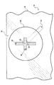
図1を参照するに、アンテナ10は、車両14の窓12と一体にされることが好適である。この窓12は、後部窓(バックライト)、前部窓(ウィンドシールド)、又は車両14の任意の他の窓であり得る。アンテナ10は更に、例えば、無線受信機と共に組み立てられるか又は一体にされる等車両14とは全く異なる他の状況においても実施され得る。窓12は、少なくとも1つの非導電性ペイン18を含む。「非導電性」という用語は、様々な電位の導体間に配置されたときに、印加された電圧と同調した電流がほんの僅かに又は無視できるほどで材料を流れることを可能にする絶縁体又は誘電体といった材料を意味する。一般的に、非導電性材料は、ナノジーメンス毎メートルのオーダの導電率を有する。
Referring to FIG. 1, the
この好適な実施例では、非導電性ペイン18は、少なくとも1つのガラスペイン16として実施される。当然ながら、窓12は、1つ以上のガラスペイン16を含んでもよい。当業者は、自動車用の窓12、特にウィンドシールドは、ポリビニールブチラール(PVB)の層を挟む2つのガラスペイン16を含み得ることを認識する。
In this preferred embodiment, the
ガラスペイン16は、自動車用ガラスであることが好適であり、より好適には、石灰−ライム−シリカガラスである。ガラスペイン16は、1.5乃至5.0ミリメートル(mm)の厚さを画成し、好適には、3.1ミリメートル(mm)である。ガラスペイン16は、5乃至9の誘電率を有し、好適には、7である。しかし、当業者は、非導電性ペイン18は、プラスチック、繊維ガラス、又は他の好適な非導電性材料から形成され得ることを認識する。
The
説明目的のためだけに、本発明は、以下において、自動車用ガラスのペイン16である最も好適な非導電性ペイン18のコンテキストにおいてのみ言及する。しかし、これは限定と解釈すべきではなく、というのは、上述したように、アンテナ10は、ガラスペイン16以外の非導電性ペイン18と共に実施可能だからである。
For illustrative purposes only, the present invention will be referred to in the following only in the context of the most preferred
図2及び3を参照するに、ガラスペイン16は、アンテナ10のレードームとして機能する。即ち、ガラスペイン16は、以下に詳細に説明するように、車両14の外に存在する湿気、風邪、埃等からアンテナ10の他の構成要素を保護する。
With reference to FIGS. 2 and 3, the
好適な実施例のアンテナ10は、ガラスペイン16上に配置される放射素子20を含む。放射素子20は、当業者によって一般的に「パッチ」又は「パッチ素子」とも称される。放射素子20は、導電性材料から形成される。放射素子20は、ガラスペイン16に直接配置され、当業者には周知である焼成技術によって硬化される導電性材料としての銀ペーストを含むことが好適である。或いは、放射素子20は、接着剤を用いてガラスペインに接着される銅又はアルミニウムといった一枚の平らな金属を有することも可能である。
The
車両14の窓12上に実装されるとき、アンテナ10のサイズは、車両14の運転手に対する視覚的な妨害とならないようできるだけ小さいべきである。図2に示す好適な実施例では、放射素子20は矩形であり、より好適には、正方形である。視覚的な妨害となってしまい得ることに対処するために、放射素子20の各辺は42ミリメートル(mm)未満であることが好適である。更に、放射素子20の各辺は、35ミリメートル(mm)乃至37ミリメートル(mm)であることが好適である。従って、放射素子20は、窓12のコンパクトな約1,300平方ミリメートル(mm2)を占めることになる。尚、図面は、縮尺がとられて描かれているわけではないことを理解すべきである。好適な実施例では、所望の周波数は約2,338メガヘルツ(MHz)であり、これは、XM(商標)衛星ラジオによって使用される中心周波数に対応する。従って、放射素子20の各辺は、2,338メガヘルツ(MHz)における性能を最適にするためのサイズにされる。図4に示すような第1の別の実施例では、放射素子20は、円形であり、42ミリメートル(mm)未満の直径を有する。当然ながら、当業者は、アンテナ10の同様の性能結果を達成するために様々な形状及びサイズの放射素子20を実施し得ることを認識する。
When mounted on the
図2を再び参照するに、放射素子20は、互いに略垂直である第1の脚24及び第2の脚26を有するスロット22を画成する。スロット22は、中心点を有する十字型の外周を形成する。スロット22は、放射素子20において中心にされることが好適である。
Referring again to FIG. 2, the radiating
この好適な実施例では、スロット22の第1の脚24は、第1の長さL1を有し、スロット22の第2の脚26は、第2の長さL2を有する。第1の長さL1は、第2の長さL2と同じではない。十字型スロット22のこれらの等しくない長さL1、L2は、放射素子20に、衛星からの円偏波されたRF信号を受信するための円偏波を与える。当業者は、各脚24、26は更に、放射素子20に、直線偏波RF信号を受信するための直線偏波を与えることを認識する。スロット22の脚24、26の正確な長さL1、L2は、アンテナ10の所望の周波数範囲、リターンロス、及び軸比によって決定される。好適な実施例の2,338メガヘルツ(MHz)周波数における最適化のために、第1の長さL1は、13.1ミリメートル(mm)乃至15.1ミリメートル(mm)であり、第2の長さL2は、7.6ミリメートル(mm)乃至9.6ミリメートル(mm)である。各脚24、26は更に、1ミリメートル乃至3ミリメートルの幅を有することが好適である。当然ながら、脚24、26の他の寸法範囲も、アンテナ10の所望される最適な動作周波数範囲、リターンロス、及び軸比に依存して、円偏波とアンテナ10の適切な動作のために好適である。更に、当業者は、等しくない長さの脚24、26を有する十字型のスロット22以外にも円偏波を生成する他の技術が実施し得ることを認識する。例えば、円偏波は、第1の幅W1を有する第1の脚24と、第1の幅W1とは同じではない第2の幅W2を有する第2の脚26とによって、同時に、第1の長さと第2の長さは実質的に同じで、生成され得る。
In the preferred embodiment, the
放射素子20が矩形である好適な実施例では、スロット20の各脚24、26は、放射素子20の2つの辺と略平行である。当然ながら、放射素子20の辺に対する脚24、26の他の向きが可能である。例えば、図5に示すような第2の別の実施例では、脚24、26は、放射素子20の各辺について略45°の角度にある。
In the preferred embodiment where the radiating
図3を再び参照するに、アンテナ10は更に、接地面28を含む。接地面28は、放射素子20に対して実質的に平行に配置され且つ放射素子20から間隔が置かれる。接地面28は、導電性材料から形成される。この好適な実施例では、接地面28は、矩形である。放射素子20の寸法に合うように、接地面28の各辺は、約36ミリメートルであることが好適である。更に、放射素子20と接地面28は、互いに対して中心が合わされることが好適である。この同様の寸法と向きは、車両14の運転手に対する追加の視覚的な妨害を回避する。しかし、当業者は、接地面28は、別のサイズ及び形状を有し得ることを認識する。特に、接地面28が放射素子20の面積より大きい面積を有することが一般的である。
Referring back to FIG. 3, the
アンテナ10は更に、誘電体基板30を含む。誘電体基板30は、放射素子20と接地面28との間に挟まれる。誘電体基板30は、端面31を示す。誘電体層30は、非導電性材料から形成され、放射素子20を接地面28から絶縁する。従って、放射素子20は及び接地面38は、導電性材料によって電気接続されていない。当業者は、誘電体基板30は、空気であり得ることを認識する。
The
この好適な実施例では、誘電体基板30は、放射素子20と接地面28とに接触して配置される。当然ながら、誘電体基板30は、放射素子20と接地面28との間で、放射素子28及び/又は接地面28と直接接触することなく挟まれてもよい。更に、誘電体基板30は、誘電体基板30の少なくとも一部分が放射素子20と接地面28との間にある限り放射素子20及び接地面28によって画成される面積を超えて延在してもよい。
In this preferred embodiment, the
誘電体基板30は、約3.2ミリメートル(mm)の誘電体基板厚さを有することが好適である。更に、誘電体基板30は、約2.6の誘電率を有することが好適である。しかし、当業者は、誘電体基板30は、他の寸法及び/又は誘電率を有し得ることを認識する。更に、誘電体基板30は、複数の層又は領域から構成されてもよい。これらの各層又は領域の誘電率は、互いに同一であるか、又は、互いから異なってもよい。
The
アンテナ10は更に、導電性給電線32を含む。給電線32は、放射素子20及び接地面30に電磁気的に結合されることが好適である伝送デバイスである。「電磁的に結合」という用語は、当該技術において使用されるように、給電線32は、放射素子20と直接接触していないことを意味する。本発明の場合では、給電線32は、放射素子20及び接地面28と略平行に延在する。しかし、当業者は、給電線32は、放射素子20に直接接続される、即ち、給電線32は、放射素子20と直接接触し得ることを理解する。
The
給電線32は、誘電体基板30の端面31から誘電体基板30内に延在する遠位端34を含む。給電線32は、スロット22の中心点の手前の遠位端34において終端する。遠位端34は、スロット22の中心点から12ミリメートル(mm)未満で終端する。この好適な実施例では、給電線32は、約4.5ミリメートル(mm)の幅を有する矩形である。更に、給電線32は、アンテナ10の円偏波を適切に生成するためにスロット22の脚に対して約45°の角度で配置されることが好適である。当業者は、アンテナ10の所望の使用に依存して別の寸法の給電線32を実施し得ることを認識する。更に、給電線32の寸法は、チューニング目的のために変更され得る。即ち、アンテナ10の入力インピーダンスをアンテナ10に接続される伝送線と適合させるために変更され得る。
The
図6を参照するに、アンテナ10は、アンテナ10によって受信された信号を増幅するために、給電線32に電気接続される増幅器36も含み得る。増幅器36は、アンテナ10によって受信されたRF信号を増幅し、増幅された信号を供給する。増幅器36は、当業者には周知である低雑音増幅器(LNA)36であることが好適である。受信器38は次に、増幅された信号を処理し、オーディオ信号をスピーカ40に供給する。
Referring to FIG. 6, the
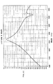
上述したような実施例では、給電線32は、スロット22の中心点を越えて延在しない。このことは、アンテナ10の例外の放射利得と他の性能特性への有意な寄与を与える。図7を参照するに、好適な実施例において実施されるようなアンテナ10は、所望の周波数2,338メガヘルツ(MHz)において6.7デシベル(dB)のLHCP利得を与える。好適な実施例のアンテナ10は更に、図8に示すように、2,338メガヘルツ(MHz)において、0.8デシベル(dB)の軸比を与える。アンテナ10は、2,338メガヘルツ(MHz)において、25.4デシベル(dB)のリターンロスを与える。この最良のリターンロスは、アンテナに、図9に示すように99%の効率を与える。当業者は、アンテナ10の効率は、増幅器36に実際に渡されたアンテナによって受信されたRF信号の比率に関連することを認識する。図示する効率曲線は、好適な実施例において実施されるようなアンテナ10が、約3,550メガヘルツ(MHz)において中心が合わされる第2の周波数帯域でも良好に動作することを明らかにする。上述した性能特性により示されるように、アンテナ10は、2,338メガヘルツ(MHz)において最高の円偏波を示すだけでなく、この周波数における直線偏波も与える。従って、アンテナ10は、二重帯域アンテナの特性を示す。
In the embodiment as described above, the
図3に示すようなカバー42が、接地面28、放射素子20、及び誘電体基板30を閉じ込めるようガラスペイン16に取り付けられ得る。カバー42は、アンテナ10を埃、汚れ、汚染物質、不測の破損等から保護し、更に、アンテナ10に審美的な外観を与える。
A
好適な実施例のガラスペイン16は、上述したように、7の誘電率を有することが好適である。従って、ガラスペイン16は、アンテナ10の性能特性に影響を与える。当業者には、アンテナ10は、非導電性ペイン18がガラスペイン16以外の材料である別の実施例において同様の性能のために変更(チューニング)され得ることを理解する。
The
複数のアンテナ10も、アンテナ10のダイバーシティシステムの一部として実施され得る。例えば、好適な実施例の車両14は、ウィンドシールド上に第1のアンテナ10を、バックライト上に第2のアンテナを含み得る。これらのアンテナ10はそれぞれ、車両14内の受信器に電気接続される別個のLNA36を有し得る。当業者は、ダイバーシティ受信を達成するために幾つかの処理技術を使用し得ることを認識する。1つのそのような技術では、衛星から最も強いRF信号を現在受信するアンテナ10を選択するためのスイッチが使用される。
当然ながら、上述の教示内容を鑑みて本発明の多くの修正及び変更が可能である。本発明は、特許請求の範囲に具体的に記載される以外でも実施され得る。 Of course, many modifications and variations of the present invention are possible in light of the above teachings. The invention may be practiced otherwise than as specifically described in the claims.
10 アンテナ
12 窓
14 車両
16 ガラスペイン
18 非導電性ペイン
20 放射素子
22 スロット
24 第1の脚
26 第2の脚
28 接地面
30 誘電体基板
31 端面
32 給電線
34 給電線の遠端
36 増幅器
38 受信器
40 スピーカ
42 カバー
DESCRIPTION OF
Claims (19)
非導電性ペインと、
十字型の外周を形成するよう互いに略垂直である第1の脚及び第2の脚を有するスロットを画成する、前記非導電性ペイン上に配置される放射素子と、
前記放射素子と実質的に平行に且つ前記放射素子から間隔が置かれて配置される接地面と、
前記接地面から前記放射素子を絶縁させるよう前記放射素子と前記接地面との間に挟まれる誘電体基板と、
前記誘電体基板内に配置される導電性給電線と、
を含む窓。 A window having an integrated antenna,
A non-conductive pane;
A radiating element disposed on the non-conductive pane defining a slot having a first leg and a second leg that are substantially perpendicular to each other to form a cross-shaped perimeter;
A ground plane disposed substantially parallel to and spaced from the radiating element;
A dielectric substrate sandwiched between the radiating element and the ground plane to insulate the radiating element from the ground plane;
A conductive feeder line disposed in the dielectric substrate;
Including windows.
前記誘電体基板は、端面を示し、
前記給電線は、遠位端を含む請求項1記載の窓。 The slot has a center point;
The dielectric substrate shows an end face;
The window of claim 1, wherein the feeder line includes a distal end.
前記放射素子と実質的に平行に且つ前記放射素子から間隔が置かれて配置される接地面と、
前記放射素子と前記接地面との間に挟まれ、端面を示す誘電体基板と、
遠位端を有し、前記誘電体基板の前記端面から前記誘電体基板内を延在し、前記スロットの前記中心点の手前の該遠位端において終端する導電性給電線と、
を有するアンテナ。 A radiating element defining a slot having a first leg and a second leg that are substantially perpendicular to each other to form a cross-shaped outer periphery having a center point;
A ground plane disposed substantially parallel to and spaced from the radiating element;
A dielectric substrate sandwiched between the radiating element and the ground plane and showing an end surface;
A conductive feed line having a distal end, extending from the end face of the dielectric substrate into the dielectric substrate and terminating at the distal end before the center point of the slot;
Having an antenna.
前記放射素子は、前記非導電性ペイン上に配置される請求項11記載のアンテナ。 In combination with non-conductive panes,
The antenna of claim 11, wherein the radiating element is disposed on the non-conductive pane.
Applications Claiming Priority (1)
| Application Number | Priority Date | Filing Date | Title |
|---|---|---|---|
| US11/025,499 US7126549B2 (en) | 2004-12-29 | 2004-12-29 | Slot coupling patch antenna |
Publications (2)
| Publication Number | Publication Date |
|---|---|
| JP2006191574A true JP2006191574A (en) | 2006-07-20 |
| JP2006191574A5 JP2006191574A5 (en) | 2008-03-27 |
Family
ID=36610816
Family Applications (1)
| Application Number | Title | Priority Date | Filing Date |
|---|---|---|---|
| JP2005368572A Pending JP2006191574A (en) | 2004-12-29 | 2005-12-21 | Slot coupled patch antenna |
Country Status (3)
| Country | Link |
|---|---|
| US (1) | US7126549B2 (en) |
| JP (1) | JP2006191574A (en) |
| CN (1) | CN1797845A (en) |
Cited By (6)
| Publication number | Priority date | Publication date | Assignee | Title |
|---|---|---|---|---|
| JP2008130019A (en) * | 2006-11-24 | 2008-06-05 | China Steel Corp | Radio identification tag device |
| JP2010118982A (en) * | 2008-11-14 | 2010-05-27 | Nec Corp | Array antenna |
| US8432315B2 (en) | 2009-12-01 | 2013-04-30 | Kia Motors Corporation | Patch antenna |
| JP2013138286A (en) * | 2011-12-28 | 2013-07-11 | Toko Inc | Waveguide slot antenna |
| KR20190061768A (en) * | 2017-11-28 | 2019-06-05 | 한국전자통신연구원 | Security paper based rf tag using frequency selective surface structure and method for manufacturing thereof |
| WO2020071390A1 (en) * | 2018-10-05 | 2020-04-09 | Agc株式会社 | Antenna system |
Families Citing this family (31)
| Publication number | Priority date | Publication date | Assignee | Title |
|---|---|---|---|---|
| US7667589B2 (en) * | 2004-03-29 | 2010-02-23 | Impinj, Inc. | RFID tag uncoupling one of its antenna ports and methods |
| US7528728B2 (en) * | 2004-03-29 | 2009-05-05 | Impinj Inc. | Circuits for RFID tags with multiple non-independently driven RF ports |
| US7423539B2 (en) * | 2004-03-31 | 2008-09-09 | Impinj, Inc. | RFID tags combining signals received from multiple RF ports |
| US7522114B2 (en) * | 2005-02-09 | 2009-04-21 | Pinyon Technologies, Inc. | High gain steerable phased-array antenna |
| US7791437B2 (en) * | 2007-02-15 | 2010-09-07 | Motorola, Inc. | High frequency coplanar strip transmission line on a lossy substrate |
| US7746283B2 (en) * | 2007-05-17 | 2010-06-29 | Laird Technologies, Inc. | Radio frequency identification (RFID) antenna assemblies with folded patch-antenna structures |
| US7786944B2 (en) * | 2007-10-25 | 2010-08-31 | Motorola, Inc. | High frequency communication device on multilayered substrate |
| TWI355111B (en) * | 2008-01-31 | 2011-12-21 | Yfy Rfid Technologies Company Ltd | Antenna system and antenna thereof |
| US20120249375A1 (en) * | 2008-05-23 | 2012-10-04 | Nokia Corporation | Magnetically controlled polymer nanocomposite material and methods for applying and curing same, and nanomagnetic composite for RF applications |
| CN101771195A (en) * | 2008-12-30 | 2010-07-07 | 数伦计算机技术(上海)有限公司 | Plane antenna and RFID tag using the same |
| CN101562359B (en) * | 2009-05-26 | 2011-11-23 | 上海大学 | High-conversion efficiency circularly polarized rectenna |
| GB0922191D0 (en) | 2009-12-21 | 2010-02-03 | Pilkington Group Ltd | Vehicle glazing |
| US20110193759A1 (en) * | 2010-02-08 | 2011-08-11 | You-Cheng You | Antenna Device |
| GB201105949D0 (en) * | 2011-04-07 | 2011-05-18 | Imagination Tech Ltd | Vehicle antenna |
| KR101962499B1 (en) | 2011-10-28 | 2019-03-26 | 코닝 인코포레이티드 | Glass articles with infrared reflectivity and methods for making the same |
| US9123995B2 (en) * | 2012-03-06 | 2015-09-01 | City University Of Hong Kong | Dielectric antenna and method of discretely emitting radiation pattern using same |
| JP2014060692A (en) * | 2012-08-24 | 2014-04-03 | Fujitsu Ltd | Proximity field antenna |
| JP6160687B2 (en) * | 2013-02-21 | 2017-07-12 | 旭硝子株式会社 | Vehicle window glass and antenna |
| EA034740B1 (en) | 2014-12-16 | 2020-03-16 | Сэн-Гобэн Гласс Франс | Electrically heatable antenna pane and method for producing same |
| WO2016162251A1 (en) | 2015-04-08 | 2016-10-13 | Saint-Gobain Glass France | Vehicle window aerial pane |
| KR101973311B1 (en) * | 2015-04-08 | 2019-04-26 | 쌩-고벵 글래스 프랑스 | Antenna glass plate |
| CN107531562B (en) | 2015-04-30 | 2021-05-28 | 康宁股份有限公司 | Conductive articles having discrete metallic silver layers and methods of making the same |
| US9710746B2 (en) | 2015-06-01 | 2017-07-18 | The Penn State Research Foundation | Radio frequency identification antenna apparatus |
| US10170839B2 (en) * | 2016-05-16 | 2019-01-01 | City University Of Hong Kong | Circularly polarized planar aperture antenna with high gain and wide bandwidth for millimeter-wave application |
| US10673122B2 (en) * | 2017-10-20 | 2020-06-02 | Gentex Corporation | Vehicle communication module with improved transmission |
| USD924210S1 (en) * | 2018-05-11 | 2021-07-06 | Skyworks Solutions, Inc. | Antenna |
| WO2020187602A1 (en) | 2019-03-21 | 2020-09-24 | Saint-Gobain Glass France | Vehicle pane |
| JPWO2021112032A1 (en) * | 2019-12-03 | 2021-06-10 | ||
| CA3163880A1 (en) | 2019-12-06 | 2021-06-10 | Pittsburgh Glass Works Llc | Multilayer glass patch antenna |
| CN112467353B (en) * | 2020-11-20 | 2023-12-08 | Oppo广东移动通信有限公司 | Antenna device and electronic equipment |
| CN114976597B (en) * | 2022-05-26 | 2024-03-01 | 福耀玻璃工业集团股份有限公司 | Vehicle-mounted glass integrated with antenna, manufacturing method and vehicle |
Citations (2)
| Publication number | Priority date | Publication date | Assignee | Title |
|---|---|---|---|---|
| JPH03259603A (en) * | 1990-03-09 | 1991-11-19 | Toshiba Corp | Circularly polarized wave microstrip antenna |
| WO2004095639A1 (en) * | 2003-04-24 | 2004-11-04 | Asahi Glass Company, Limited | Antenna device |
Family Cites Families (32)
| Publication number | Priority date | Publication date | Assignee | Title |
|---|---|---|---|---|
| US4761654A (en) | 1985-06-25 | 1988-08-02 | Communications Satellite Corporation | Electromagnetically coupled microstrip antennas having feeding patches capacitively coupled to feedlines |
| US4903033A (en) | 1988-04-01 | 1990-02-20 | Ford Aerospace Corporation | Planar dual polarization antenna |
| US4916457A (en) | 1988-06-13 | 1990-04-10 | Teledyne Industries, Inc. | Printed-circuit crossed-slot antenna |
| FR2651926B1 (en) | 1989-09-11 | 1991-12-13 | Alcatel Espace | FLAT ANTENNA. |
| US5241321A (en) | 1992-05-15 | 1993-08-31 | Space Systems/Loral, Inc. | Dual frequency circularly polarized microwave antenna |
| GB9220414D0 (en) | 1992-09-28 | 1992-11-11 | Pilkington Plc | Patch antenna assembly |
| GB9417401D0 (en) | 1994-08-30 | 1994-10-19 | Pilkington Plc | Patch antenna assembly |
| JP3455039B2 (en) * | 1996-03-07 | 2003-10-06 | 日本板硝子株式会社 | Automotive window glass and automotive window structure using this glass |
| SE507076C2 (en) | 1997-01-24 | 1998-03-23 | Allgon Ab | Antenna element |
| JP3684285B2 (en) | 1997-03-10 | 2005-08-17 | 株式会社日立製作所 | Tunable slot antenna |
| US5880694A (en) | 1997-06-18 | 1999-03-09 | Hughes Electronics Corporation | Planar low profile, wideband, wide-scan phased array antenna using a stacked-disc radiator |
| EP0920074A1 (en) | 1997-11-25 | 1999-06-02 | Sony International (Europe) GmbH | Circular polarized planar printed antenna concept with shaped radiation pattern |
| JPH11251829A (en) | 1998-02-27 | 1999-09-17 | Kyocera Corp | Slot antenna and wiring board provided with the same |
| US6097345A (en) | 1998-11-03 | 2000-08-01 | The Ohio State University | Dual band antenna for vehicles |
| US6054953A (en) | 1998-12-10 | 2000-04-25 | Allgon Ab | Dual band antenna |
| AUPQ204599A0 (en) | 1999-08-05 | 1999-08-26 | R F Industries Pty Ltd | Dual band antenna |
| US6304226B1 (en) | 1999-08-27 | 2001-10-16 | Raytheon Company | Folded cavity-backed slot antenna |
| US6407704B1 (en) | 1999-10-22 | 2002-06-18 | Lucent Technologies Inc. | Patch antenna using non-conductive thermo form frame |
| US6329950B1 (en) | 1999-12-06 | 2001-12-11 | Integral Technologies, Inc. | Planar antenna comprising two joined conducting regions with coax |
| TW480771B (en) | 1999-12-15 | 2002-03-21 | Tdk Corp | Microwave transmission band antenna |
| SE524641C2 (en) | 2000-02-22 | 2004-09-07 | Smarteq Wireless Ab | An antenna device and an antenna assembly |
| US6507320B2 (en) | 2000-04-12 | 2003-01-14 | Raytheon Company | Cross slot antenna |
| US6518930B2 (en) | 2000-06-02 | 2003-02-11 | The Regents Of The University Of California | Low-profile cavity-backed slot antenna using a uniplanar compact photonic band-gap substrate |
| US6359593B1 (en) | 2000-08-15 | 2002-03-19 | Receptec Llc | Non-radiating single slotline coupler |
| DE60122077T2 (en) | 2000-09-14 | 2007-02-15 | Asahi Glass Co., Ltd. | Laminated glass |
| EP1193048B2 (en) | 2000-09-29 | 2014-09-03 | Asahi Glass Company, Limited | Laminated glass and automobile employing it |
| EP1215039B1 (en) | 2000-12-06 | 2012-06-06 | Asahi Glass Company, Limited | Laminated glass and glass plate used for producing laminated glass |
| US6733872B2 (en) | 2001-03-01 | 2004-05-11 | Asahi Glass Company, Limited | Laminated glass |
| WO2002070293A1 (en) | 2001-03-02 | 2002-09-12 | Asahi Glass Company, Limited | Window glass for car and method of recycling the window glass |
| US6646618B2 (en) * | 2001-04-10 | 2003-11-11 | Hrl Laboratories, Llc | Low-profile slot antenna for vehicular communications and methods of making and designing same |
| US6593891B2 (en) | 2001-10-19 | 2003-07-15 | Hitachi Cable, Ltd. | Antenna apparatus having cross-shaped slot |
| US6778144B2 (en) | 2002-07-02 | 2004-08-17 | Raytheon Company | Antenna |
-
2004
- 2004-12-29 US US11/025,499 patent/US7126549B2/en not_active Expired - Fee Related
-
2005
- 2005-12-21 CN CN200510132321.8A patent/CN1797845A/en active Pending
- 2005-12-21 JP JP2005368572A patent/JP2006191574A/en active Pending
Patent Citations (2)
| Publication number | Priority date | Publication date | Assignee | Title |
|---|---|---|---|---|
| JPH03259603A (en) * | 1990-03-09 | 1991-11-19 | Toshiba Corp | Circularly polarized wave microstrip antenna |
| WO2004095639A1 (en) * | 2003-04-24 | 2004-11-04 | Asahi Glass Company, Limited | Antenna device |
Cited By (8)
| Publication number | Priority date | Publication date | Assignee | Title |
|---|---|---|---|---|
| JP2008130019A (en) * | 2006-11-24 | 2008-06-05 | China Steel Corp | Radio identification tag device |
| JP2010118982A (en) * | 2008-11-14 | 2010-05-27 | Nec Corp | Array antenna |
| US8432315B2 (en) | 2009-12-01 | 2013-04-30 | Kia Motors Corporation | Patch antenna |
| JP2013138286A (en) * | 2011-12-28 | 2013-07-11 | Toko Inc | Waveguide slot antenna |
| KR20190061768A (en) * | 2017-11-28 | 2019-06-05 | 한국전자통신연구원 | Security paper based rf tag using frequency selective surface structure and method for manufacturing thereof |
| KR102013937B1 (en) * | 2017-11-28 | 2019-08-23 | 한국전자통신연구원 | Security paper based rf tag using frequency selective surface structure and method for manufacturing thereof |
| WO2020071390A1 (en) * | 2018-10-05 | 2020-04-09 | Agc株式会社 | Antenna system |
| JP7355027B2 (en) | 2018-10-05 | 2023-10-03 | Agc株式会社 | antenna system |
Also Published As
| Publication number | Publication date |
|---|---|
| US20060139223A1 (en) | 2006-06-29 |
| US7126549B2 (en) | 2006-10-24 |
| CN1797845A (en) | 2006-07-05 |
Similar Documents
| Publication | Publication Date | Title |
|---|---|---|
| JP2006191574A (en) | Slot coupled patch antenna | |
| JP4778945B2 (en) | Beam tilt cross dipole dielectric antenna | |
| US7119751B2 (en) | Dual-layer planar antenna | |
| US7333059B2 (en) | Compact circularly-polarized patch antenna | |
| US9270017B2 (en) | Multi-element cavity-coupled antenna | |
| JP4336727B2 (en) | Nonuniform dielectric beam steering antenna | |
| US7505002B2 (en) | Beam tilting patch antenna using higher order resonance mode | |
| US7545333B2 (en) | Multiple-layer patch antenna | |
| JP4663705B2 (en) | antenna | |
| US20060152422A1 (en) | Multiple-element beam steering antenna | |
| US20080129616A1 (en) | Circularly Polarized Dielectric Antenna | |
| US8009107B2 (en) | Wideband dielectric antenna | |
| US20110221652A1 (en) | Antenna system including a circularly polarized antenna | |
| CN107394356B (en) | CPW fed circular polarized decal antenna for GPS and SDARS bands | |
| JP4772029B2 (en) | How to operate a patch antenna in higher order mode | |
| US10707553B2 (en) | CPW-fed modified sleeve monopole for GPS, GLONASS, and SDARS bands | |
| US20110298667A1 (en) | Method of Operating A Patch Antenna In A Single Higher Order Mode | |
| JP2006173895A (en) | Diversity antenna device | |
| KR100357780B1 (en) | Antenna array attached to car glass | |
| JP2007150966A (en) | High-frequency glass windshield antenna for automobile |
Legal Events
| Date | Code | Title | Description |
|---|---|---|---|
| A521 | Request for written amendment filed |
Free format text: JAPANESE INTERMEDIATE CODE: A523 Effective date: 20080206 |
|
| A621 | Written request for application examination |
Free format text: JAPANESE INTERMEDIATE CODE: A621 Effective date: 20081029 |
|
| A977 | Report on retrieval |
Free format text: JAPANESE INTERMEDIATE CODE: A971007 Effective date: 20101224 |
|
| A131 | Notification of reasons for refusal |
Free format text: JAPANESE INTERMEDIATE CODE: A131 Effective date: 20110111 |
|
| A521 | Request for written amendment filed |
Free format text: JAPANESE INTERMEDIATE CODE: A523 Effective date: 20110411 |
|
| A02 | Decision of refusal |
Free format text: JAPANESE INTERMEDIATE CODE: A02 Effective date: 20110913 |