JP2006190415A - Optical recording medium - Google Patents
Optical recording medium Download PDFInfo
- Publication number
- JP2006190415A JP2006190415A JP2005002582A JP2005002582A JP2006190415A JP 2006190415 A JP2006190415 A JP 2006190415A JP 2005002582 A JP2005002582 A JP 2005002582A JP 2005002582 A JP2005002582 A JP 2005002582A JP 2006190415 A JP2006190415 A JP 2006190415A
- Authority
- JP
- Japan
- Prior art keywords
- information carrier
- carrier surface
- transmission layer
- light beam
- light transmission
- Prior art date
- Legal status (The legal status is an assumption and is not a legal conclusion. Google has not performed a legal analysis and makes no representation as to the accuracy of the status listed.)
- Pending
Links
Images
Landscapes
- Optical Record Carriers And Manufacture Thereof (AREA)
Abstract
【課題】 BDと互換性が高く、かつDVD機器あるいはCD機器でも再生可能な再生専用型光記録媒体を提供すること。
【解決手段】 第1の光透過層4と、第2の光透過層5と、青色光ビームで再生するための第1の情報担体面2と、赤色光ビームで再生するための第2の情報担体面3とを備え、第1の光透過層4の厚さを0.08mm〜0.12mm、第2の光透過層5の厚さを0.43mm〜0.57mm、赤色光に対する第1の情報担体面2と第2の情報担体面3の反射率をそれぞれR1R、R2Rとしたとき、第1の情報担体面2の反射率R1RをR1R≦1−(0.5/R2R)1/2とし、かつ青色光に対する第1の情報担体面2の反射率を3%以上とすることにより、DVD機器で安定した再生が可能となり、かつBDとの互換性も高くなる。
【選択図】 図1aPROBLEM TO BE SOLVED: To provide a read-only optical recording medium which is highly compatible with a BD and can be reproduced on a DVD device or a CD device.
A first light transmission layer, a second light transmission layer, a first information carrier surface for reproducing with a blue light beam, and a second for reproducing with a red light beam. An information carrier surface 3, the thickness of the first light transmission layer 4 is 0.08 mm to 0.12 mm, the thickness of the second light transmission layer 5 is 0.43 mm to 0.57 mm, When the reflectances of the first information carrier surface 2 and the second information carrier surface 3 are R 1R and R 2R , the reflectance R 1R of the first information carrier surface 2 is R 1R ≦ 1- (0.5 / R 2R ) 1/2 and the reflectance of the first information carrier surface 2 with respect to blue light is 3% or more, stable reproduction on a DVD device is possible, and compatibility with BD is high. Become.
[Selection] Figure 1a
Description
本発明は、収束された光ビームを光記録媒体(光ディスク)上に照射し、その反射光を検知して情報を再生する光記録媒体に関するものであり、特に、2つ以上の波長の光ビームを用いて再生することのできる光記録媒体に関するものである。 The present invention relates to an optical recording medium that reproduces information by irradiating a converged light beam onto an optical recording medium (optical disk), detecting the reflected light, and in particular, a light beam having two or more wavelengths. The present invention relates to an optical recording medium that can be reproduced using
光記録媒体は大容量のデータを蓄積できることから、音声データ、映像データ、あるいは様々な情報データを蓄積するメディアとして重要な地位を占めつつある。光記録媒体としては、音楽を蓄積することを主たる目的として開発されたCD(Compact Disc)、映像を蓄積することを主たる目的として開発されたDVD(Digital Versatile Disc)などが知られている。これらの光記録媒体には再生専用型、1回記録可能な追記型および繰り返し記録型の3種類がある。 Since optical recording media can store large amounts of data, they are occupying an important position as media for storing audio data, video data, or various information data. As an optical recording medium, a CD (Compact Disc) developed mainly for storing music and a DVD (Digital Versatile Disc) developed mainly for storing video are known. There are three types of these optical recording media: a read-only type, a once-recordable write-once type, and a repetitive recording type.
再生専用型CDは、厚さ約1.2mmの円盤状の樹脂基板表面に凹凸ピットよりなる情報トラックをスパイラル状に形成し、この基板の情報担体面上にスパッタリング等の手法でアルミニウム等の反射膜及び保護膜を設け、その上にディスクを識別するためのラベルを印刷したものである。 The read-only CD has an information track consisting of concave and convex pits formed in a spiral shape on the surface of a disk-shaped resin substrate having a thickness of about 1.2 mm, and aluminum or the like is reflected on the information carrier surface of the substrate by a method such as sputtering. A film and a protective film are provided, and a label for identifying the disk is printed thereon.
再生専用型DVDには、1つの情報担体面を有する単層ディスクと、一方の面から光ビームを照射させて2つの情報担体面の情報を読み取るように構成された2層ディスクの2種類がある。単層の再生専用型DVDは、厚さ約0.6mmの円盤状の樹脂基板表面に凹凸ピットよりなる情報トラックをスパイラル状に形成し、この基板の情報面上にスパッタリング等の手法でアルミニウム等の反射膜を設け、この基板の情報担体面側と約0.6mmの基板とを貼り合わせ、厚さ約1.2mmの光ディスクとしたものである。2層の再生専用型DVDは、厚さ約0.6mmの円盤状の樹脂基板表面に光を透過する半透明の第1の情報担体面を形成した第1の基板と、厚さ約0.6mmの円盤状の樹脂基板表面に光を反射する第2の情報担体面を形成した第2の基板とを、2つの情報担体面が所定の間隔で対向するように貼り合わせたものである(例えば、特許文献1参照)。 There are two types of read-only DVDs: a single-layer disc having one information carrier surface and a dual-layer disc configured to read information on two information carrier surfaces by irradiating a light beam from one surface. is there. A single-layer read-only DVD has a disk-shaped resin substrate surface with a thickness of about 0.6 mm and an information track made up of concave and convex pits formed in a spiral shape on the surface of the substrate. And an information carrier surface side of this substrate and an approximately 0.6 mm substrate are bonded together to form an optical disk having a thickness of approximately 1.2 mm. The two-layer read-only DVD has a first substrate in which a translucent first information carrier surface that transmits light is formed on the surface of a disk-shaped resin substrate having a thickness of about 0.6 mm, and a thickness of about 0.1 mm. A 6 mm disk-shaped resin substrate surface is bonded to a second substrate on which a second information carrier surface that reflects light is formed so that the two information carrier surfaces face each other at a predetermined interval ( For example, see Patent Document 1).
これらの光記録媒体は、CDプレーヤ、DVDプレーヤあるいはDVDレコーダなどの民生機器用として普及し始め、安価になるにつれてPC(Personal Computer)用のペリフェラル機器など、様々なアプリケーション機器へと展開されてきた。 These optical recording media have begun to spread for consumer devices such as CD players, DVD players, and DVD recorders, and have been developed into various application devices such as peripheral devices for PCs (Personal Computers) as they become cheaper. .
1996年に初めてDVDプレーヤが発売されたが、その当時に普及していたCD再生は必須とされ、これを実現するために、1つの光ピックアップでDVDとCDの双方を再生可能とする技術が開発された(例えば、特許文献2参照)。DVDプレーヤの普及とともに、DVDとCDの双方を再生可能とするPC用DVD−ROMドライブも普及し始めた。近年は民生用のDVDレコーダ、PC用の記録型DVDドライブが普及しつつある。PC用の記録型DVDドライブはDVDおよびCDの再生が可能で、DVD−R(DVD Recordable)、DVD−RAM(DVD Random Access Memory)などの記録型DVDへの記録は勿論のこと、CD−R(CD Recordable)、CD−RE(CD Rewritable)などの記録型CDへの記録も可能となっている。現在、これらの光記録媒体用機器の世界市場規模は年間で数億台を越え、光記録媒体の世界市場規模は年間で100億枚を越えている。 The first DVD player was put on the market in 1996, but CD playback, which was popular at that time, is essential, and in order to realize this, there is a technology that enables playback of both DVD and CD with a single optical pickup. It has been developed (see, for example, Patent Document 2). With the widespread use of DVD players, PC DVD-ROM drives capable of reproducing both DVDs and CDs have begun to spread. In recent years, DVD recorders for consumer use and recordable DVD drives for PCs are becoming widespread. A recordable DVD drive for a PC can reproduce DVDs and CDs, as well as record on a recordable DVD such as DVD-R (DVD Recordable), DVD-RAM (DVD Random Access Memory), CD-R. Recording on a recordable CD such as (CD Recordable) and CD-RE (CD Rewritable) is also possible. Currently, the global market size of these optical recording medium devices exceeds several hundred million units annually, and the global market size of optical recording media exceeds 10 billion units annually.
近年、HD(High Definition)映像を蓄積することを主たる目的とした新しい光記録媒体BD(Blu−ray Disc)の規格化が進められており(例えば、非特許文献1、2、3参照)、書換可能な光ディスクBD−RE(BD Rewritable)とそれに対応したBDレコーダが商品化された(例えば、非特許文献4、5参照)。また、追記型のBD−R(BD Recordable)、再生専用のBD−ROM(BD Read Only Memory)に関する技術も発表されている(例えば、非特許文献6、7参照)。BDは405nmの青色レーザ、開口数0.85の対物レンズを用いることにより、記録密度をDVDの約5倍に高め、光記録媒体の傾きに対する裕度を確保するために光透過層の厚みを0.1mm程度と薄くし、1つの情報担体面を有するもので25GB、2つの情報担体面を有するもので50GBという大容量化を実現している。日本で地上波デジタル放送が開始されたが、このようなテレビ放送のデジタル化、高精細度化の波は世界中に広がりつつあり、これに伴って、BDも普及していくものと予想されている。
HD放送に対応してHD−TVも徐々に普及し、これに伴って高精細度な映像で表現された映画などのコンテンツを蓄積した新しいパッケージメディアに対する要望も高まってくることが予想される。このような新しい光記録媒体を再生できる機器が普及するには、CD、DVDがそうであったように、10年程度、少なくとも数年はかかる。したがって、HD−TVと新しい光ディスクに対応した機器を接続して高画質な映像を楽しんでいる家庭において、別の部屋にSD−TV(Standard Definition TV)とDVDプレーヤあるいはDVDレコーダがセットで備え付けられているというケースが発生する。また、車に搭載されている機器はCDプレーヤあるいはDVDプレーヤである。このような状況下では、新しい光ディスクに蓄積されたコンテンツを他の機器でも見たり聞いたりしたいという要望が出て来る。 In response to HD broadcasting, HD-TV is gradually spreading, and it is expected that demand for new package media that stores contents such as movies expressed in high-definition video will increase. It will take about 10 years, at least several years, for CDs and DVDs to spread out such devices capable of reproducing such new optical recording media. Therefore, a SD-TV (Standard Definition TV) and a DVD player or DVD recorder are provided as a set in a separate room in a home where HD-TV and a device compatible with a new optical disk are connected to enjoy high-quality video. A case occurs. The device mounted on the car is a CD player or a DVD player. Under such circumstances, there is a demand for viewing and listening to content stored on a new optical disc on other devices.
しかしながら、BDのように薄型光透過層の光記録媒体をCD機器あるいはDVD機器に装填しても、光透過層の厚みが全く異なるため再生することはできないという課題を有している。 However, even if an optical recording medium having a thin light transmission layer such as a BD is loaded in a CD device or a DVD device, there is a problem that reproduction cannot be performed because the thickness of the light transmission layer is completely different.
本発明は、前述した課題を解決するためになされたもので、BDと互換性が高く、かつDVD機器あるいはCD機器でも再生可能な再生専用型光記録媒体を提供することである。 The present invention has been made to solve the above-described problems, and provides a read-only optical recording medium that is highly compatible with a BD and can be played back on a DVD device or a CD device.
前記従来の課題を解決するために、本発明の光記録媒体は、第1の光透過層と第2の光透過層との間に形成された青色光ビームで再生するための第1の情報担体面と、第2の光透過層と基板との間に形成された赤色光ビームで再生するための第2の情報担体面とを備え、第1の光透過層の厚みを0.08mm〜0.12mm、第2の光透過層の厚みを0.43mm〜0.57mm、赤色光に対する第1の情報担体面の反射率R1Rと第2の情報担体面の反射率R2Rとの関係をR1R≦1−(0.5/R2R)1/2とし、かつ青色光に対する第1の情報担体面の反射率を3%以上としたものである。 In order to solve the above-described conventional problems, the optical recording medium of the present invention provides first information for reproducing with a blue light beam formed between the first light transmission layer and the second light transmission layer. A carrier surface, and a second information carrier surface for reproducing with a red light beam formed between the second light transmission layer and the substrate, and the thickness of the first light transmission layer is 0.08 mm to The relationship between the reflectivity R 1R of the first information carrier surface and the reflectivity R 2R of the second information carrier surface for red light is 0.12 mm, the thickness of the second light transmission layer is 0.43 mm to 0.57 mm R 1R ≦ 1- (0.5 / R 2R ) 1/2 and the reflectivity of the first information carrier surface with respect to blue light is 3% or more.
本発明によれば、BDと互換性が高く、かつDVD機器あるいはCD機器でも再生可能な再生専用型光記録媒体を得ることができる。 According to the present invention, it is possible to obtain a read-only optical recording medium that is highly compatible with a BD and can be played back on a DVD device or a CD device.
以下、本発明の実施の形態について、図面を参照しながら説明する。なお、図面の説明において、同じ構成要素については同じ符号を用い、説明を省略する。 Hereinafter, embodiments of the present invention will be described with reference to the drawings. In the description of the drawings, the same components are denoted by the same reference numerals, and description thereof is omitted.
(実施の形態1)
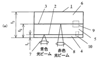
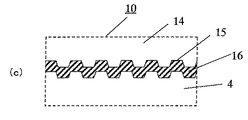
図1は、本発明の実施の形態1におけるBDと互換性が高く、かつDVD機器で再生可能な再生専用型光記録媒体の概略断面図である。図1aにおいて、光記録媒体1は青色光ビームで再生するための第1の情報担体面2と、赤色光ビームで再生するための第2の情報担体面3を備えている。4は第1の光等過層、5は第2の光透過層、6は基板である。第1の情報担体面2上の情報を読み取る場合、対物レンズ7で収束した青色光ビームを、第1の光透過層4を介して第1の情報担体面2上に収束させ、第1の情報担体面2で反射された反射光を検知して情報を読み取る。また、第2の情報担体面3上の情報を読み取る場合には、対物レンズ8で収束した赤色光ビームを、第1の光透過層4、第1の情報担体面2および第2の光透過層5を介して第2の情報担体面3上に収束させ、第2の情報担体面3で反射された反射光を検知して情報を読み取る。図1bは図1aの部位9の拡大図であり、基板6の表面には凹凸ピット11が形成され、その上に反射膜12が形成されている。基板6と基板14とは透明な接着材で接着されている。13はその接着層である。第2の光透過層5は基板14と接着層13より構成されている。図1cは図1aの部位10の拡大図であり、基板14の表面には凹凸ピット15が形成され、その上に半透明の反射膜16が形成されている。そして、半透明の反射膜16上にスピンコートなどの手法により第1の光透過層4が形成されている。
(Embodiment 1)
FIG. 1 is a schematic cross-sectional view of a read-only optical recording medium that is highly compatible with the BD in
基板6および基板14の表面に形成されている凹凸ピットはCD、DVDなどで用いられている射出成形という手法で形成することができる。また、反射膜12は金(Au)、アルミニウム(Al)、Ag等の材料、またはこれらを含んだ材料が好適である。半透明の反射膜16としては、金(Au)、アルミニウム(Al)、Ag、あるいはSi等の材料、またはこれらの材料を含んだ材料が好適である。これらの材料は従来から知られているスパッタリング等の手法で形成することができる。また、接着層13の材料として、例えば、紫外線を照射することにより硬化する紫外線硬化材料、熱を与えることにより硬化する熱硬化型接着剤、あるいは力を付与することにより硬化する加圧硬化型接着剤などを用いることができる。また、第1の光等過層4は、紫外線硬化材料を所定の厚さとなるようにスピンコートし、その後に紫外線を照射して硬化させることで作成することができる。また、熱硬化性の材料あるいは加圧硬化型の材料を用いて作成することもできる。
The concavo-convex pits formed on the surfaces of the
光記録媒体1がDVD機器で再生できるようにするためには、反射率および光透過層の厚さ等が重要である。先ず、各層の厚さについて以下に説明する。
In order to enable the
第1の光透過層4の厚さt1は0.08mm≦t1≦0.12mmである。DVD機器で再生できるようにするために、厚さt2は0.55mm≦t2≦0.65mmとしている。したがって、第2の光透過層5の厚さ、すなわち基板14と接着層13の合計の厚さは043mm以上、0.57mm以下である。また、光記録媒体1の厚さt3は1.1mm≦t3≦1.4mmであり、したがって基板6の厚さは0.45mm以上、0.85mm以下である。
The thickness t 1 of the first
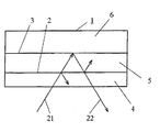
次に反射率について図2とともに説明する。21は第2の情報担体面3上の情報を読み取るために光記録媒体1に入射された赤色光ビーム、22は第2の情報担体面3上より反射された検出赤色光ビームである。図2に示すように、入射赤色光ビーム21は第1の情報担体面2で一部の光ビームが反射された後に第2の情報担体面3で反射される。第2の情報担体面3で反射された反射光ビームは第1の情報担体面2で再び一部の光ビームが反射される。また、第1の情報担体面2を赤色光ビームが透過するときに、光吸収あるいは乱反射などで5%程度のロス、すなわち往復で10%程度のロスが発生する。したがって、第1の情報担体面2の反射率をR1R、第2の情報担体面3の反射率をR2R、入射赤色光ビーム21の光量をP1、検出赤色光ビーム22の光量をP2とすると、
P2/P1=0.9×(1−R1R)×(1−R1R)×R2R・・・・・・(1)
となる。DVD機器で第2の情報担体面3上の情報を読み取るために、P2/P1≧0.45となるようにする必要がある。そこで、第1の情報担体面2の反射率R1Rの上限を、
0.9×(1−R1R)×(1−R1R)≧0.45/R2R
∴R1R≦1−(0.45/R2R/0.9)1/2・・・・・・・・・・(2)
としている。
Next, the reflectance will be described with reference to FIG.
P 2 / P 1 = 0.9 × (1-R 1R ) × (1-R 1R ) × R 2R (1)
It becomes. In order to read information on the second
0.9 × (1-R 1R ) × (1-R 1R ) ≧ 0.45 / R 2R
∴R 1R ≦ 1- (0.45 / R 2R /0.9) 1/2 (2)
It is said.
アルミニウムなどで反射膜12を形成する場合、反射膜12の厚さを厚くすればする程、反射率は高くなるが、第2の情報担体面3の反射率R2Rは0.9程度が限界である。この場合、R1R≦0.25、すなわち第1の情報担体面2の反射率R1Rは25%以下となる。また、コスト、信号品質などを考慮すると、反射率R2Rは0.65≦R2R≦0.9とすることが望ましい。R2Rが0.65この場合、R1Rは約0.12となる。すなわち、第1の情報担体面2の反射率R1Rを12%以下とすれば、赤色光ビームで再生する際に良好な再生信号が得られ、かつ光記録媒体1を安価にすることができる。
If aluminum or the like to form a
第1の情報担体面2の反射率R1Rを小さくすればする程、赤色光ビームでの読み取り性能は高まるが、青色光ビームで第1の情報担体面2上の情報を読み取る際の反射光が小さくなり、信号品質が低下するために情報の読み取りが困難となる。
The smaller the reflectance R 1R of the first
BDでは1−7PPと呼ばれる変調方式を採用し、単層ディスクで25GBの容量となっている。17PP変調方式は、2T(Tはチャンネルクロックの周期)から8Tまでの長さのピット(マーク)をもつPLL(1,7)変調コードで、最短の2Tピットの長さは約0.149μmである。波長405nmの青色光ビームを開口数0.85の対物レンズで絞って第1の情報担体面2上に収束させたとき、最短ピットの振幅は最長ピット(8Tピット)のそれの10%程度となる。したがって、第1の情報担体面2は最短ピットの信号品質を確保できる反射率を備えている必要がある。
The BD employs a modulation method called 1-7PP, and has a capacity of 25 GB with a single-layer disc. The 17PP modulation method is a PLL (1, 7) modulation code having a pit (mark) with a length from 2T (T is the period of the channel clock) to 8T, and the shortest 2T pit has a length of about 0.149 μm. is there. When a blue light beam having a wavelength of 405 nm is focused by the objective lens having a numerical aperture of 0.85 and converged on the first
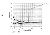
図3aは横軸を周波数、縦軸をノイズレベルとしてノイズの周波数分布を示した図である。31は光を照射しないときの回路ノイズ分布である。32は第1の情報担体面2上に記録されている単一の2T信号を0.3mWの青色光ビームを照射して再生したときのノイズ分布を示し、32aはそのときの2T信号のレベルを示している。2T信号は振幅が小さいため、40dB弱のC/N(Carrier to Noise Ratio)しか得られないことが判る。図3bは第1の情報担体面2上に記録されているランダム信号を0.3mWの青色光ビームを照射して再生したときの、第1の情報担体面2の反射率とジッタの関係を示した図である。曲線33は通常のリニアなイコライザーを介した後に再生信号を2値化したときのジッタ、曲線34はリミットイコライザーを介した後に再生信号を2値化したときのジッタをそれぞれ示している。
FIG. 3a is a diagram showing the frequency distribution of noise with the horizontal axis representing frequency and the vertical axis representing noise level.
一般的に通常のリニアなイコライザーを用いたときのジッタとして15%程度が限界とされている。図3bでは反射率2%でもジッタは15%以下であるが、機器で再生するときには様々な外乱による再生信号の劣化が発生するため、これを考慮して決める必要がある。すなわち、光記録媒体1には傾きや面ぶれ、偏心などがある。また、機器は振動や衝撃などの外乱を受ける。これらによる再生信号の劣化を考慮すると、通常の状態では13%以下とすることが望ましい。また、図3bより明らかなように、反射率3%以下では急激にジッタが劣化する。これらを勘案し、第1の情報担体面2の反射率を3%以上としている。
Generally, a limit of about 15% is set as a jitter when a normal linear equalizer is used. In FIG. 3b, even if the reflectance is 2%, the jitter is 15% or less. However, the reproduction signal deteriorates due to various disturbances when it is reproduced by the apparatus, and it is necessary to determine this in consideration of this. That is, the
かかる構成によれば、第1の光透過層の厚みを0.08mm〜0.12mm、第2の光透過層の厚みを0.43mm〜0.57mm、赤色光に対する第1の情報担体面と第2の情報担体面の反射率をそれぞれR1R、R2Rとしたとき、第1の情報担体面の反射率R1RをR1R≦1−(0.5/R2R)1/2とし、かつ青色光に対する第1の情報担体面2の反射率を3%以上とすることにより、DVD機器で安定した再生が可能となり、かつBDとの互換性も高い再生専用型光記録媒体とすることができる。また、赤色光に対する第1の情報担体面の反射率R1Rを12%以下、青色光に対する第1の情報担体面2の反射率を3%以上とすれば、赤色光ビームで再生する際に良好な再生信号が得られ、かつ光記録媒体を安価にすることができる。
According to this configuration, the thickness of the first light transmission layer is 0.08 mm to 0.12 mm, the thickness of the second light transmission layer is 0.43 mm to 0.57 mm, and the first information carrier surface for red light When the reflectance of the second information carrier surface is R 1R and R 2R , the reflectance R 1R of the first information carrier surface is R 1R ≦ 1- (0.5 / R 2R ) 1/2 , In addition, by setting the reflectance of the first
図1を用いて本発明の実施の形態1を説明したが、本発明はこれに限定されない。例えば、本発明の光記録媒体1における第2の情報担体面3は図4に示すように構成することができる。図4は図1aの部位9の拡大図であり、第2の光透過層5の表面に凹凸ピット11が形成され、その上に反射膜12が形成されている。そして、基板6と第2の光透過層5とは接着材で接着されている。41はその接着層である。すなわち、第2の光透過層5は、一方の表面に第2の情報担体面3用の凹凸ピット11が形成され、他方の表面に第1の情報担体面2用の凹凸ピット15が形成されている。この場合、当然のことであるが、第2の光透過層5の厚さは043mm以上、0.57mm以下であり、接着層41と基板6の合計の厚さは、0.45mm以上、0.85mm以下である。接着層41の材料として、接着層13と同様に、紫外線硬化材料、熱硬化型接着剤、あるいは加圧硬化型接着剤などを用いることができる。
Although
また、本発明の光記録媒体1における第1の情報担体面2は図5に示すように構成することができる。図5は図1aの部位10の拡大図であり、第2の光透過層5の表面に凹凸ピット15が形成され、その上に半透明の反射膜16を形成し、さらにその上に薄いシート51を接着している。52はシート51と第2の光透過層5とを接着している接着層であり、この場合、第1の光透過層4はシート51と接着層52とより構成される。接着層52の接着剤としては、接着層13と同様に、紫外線硬化材料、熱硬化型接着剤あるいは加圧硬化型接着剤などを用いることができる。当然のことであるが、この場合、シート51と接着層52の合計の厚さは、0.08mm以上、0.12mm以下である。
The first
また、図5の構成において、第2の光透過層5の表面に形成している凹凸ピット15の代わりに、シート51の表面に凹凸ピット15を形成することができる。この場合、シート51の表面に形成されている凹凸ピット15上に半透明の反射膜16を形成し、透明の基板と接着すれば良い。当然のことではあるが、この場合、シート51が第1の光透過層4となり、第2の光透過層5は接着層と透明基板とより構成される。したがって、シート51の厚さを0.08mm〜0.12mm、接着層と透明基板の合計の厚さを0.43mm〜0.57mmとなるようにすれば良い。
Further, in the configuration of FIG. 5, the
(実施の形態2)
図6は、本発明の実施の形態2における赤色光ビームで再生するための2つの情報担体面を備え、BDと互換性が高く、かつDVD機器で再生可能な再生専用型光記録媒体の概略断面図である。図6aにおいて、光記録媒体61は青色光ビームで再生するための第1の情報担体面2と、赤色光ビームで再生するための第2と第3の情報担体面3a、3bを備えている。第2の情報担体面3a上の情報を読み取る場合には、対物レンズ8で収束した赤色光ビームを、第1の光透過層4、第1の情報担体面2および第2の光透過層5を介して第2の情報担体面3a上に収束させ、第2の情報担体面3aで反射された反射光を検知して情報を読み取る。同様に、第3の情報担体面3b上の情報を読み取る場合には、対物レンズ8で収束した赤色光ビームを、第1の光透過層4、第1の情報担体面2、第2の光透過層5、第2の情報担体面3aを介して第3の情報担体面3b上に収束させ、第3の情報担体面3bで反射された反射光を検知して情報を読み取る。
(Embodiment 2)
FIG. 6 shows an outline of a read-only optical recording medium that has two information carrier surfaces for reproducing with a red light beam in
図6bは図6aの部位63の拡大図である。第2の光透過層5の表面には凹凸ピット11aが形成され、その上に半透明の反射膜64が形成されている。すなわち、第2の光透過層5の一方の表面には凹凸ピット11aが形成され、他方の面には青色光ビームで読み取るための凹凸ピット15が設けられている。基板6の表面には凹凸ピット11bが形成され、その上に反射膜65が形成されている。第2の光透過層5と基板6はその間隔t4が所定の間隔となるように透明な接着材で接着されている。62はその接着層である。半透明の反射膜64としては、金(Au)、アルミニウム(Al)、Ag、あるいはSi等の材料、またはこれらの材料を含んだ材料が好適である。また、反射膜65としては金(Au)、アルミニウム(Al)、Ag等の材料、またはこれらを含んだ材料が好適である。接着層62の材料として、例えば、紫外線を照射することにより硬化する紫外線硬化材料、熱を与えることにより硬化する熱硬化型接着剤、あるいは力を付与することにより硬化する加圧硬化型接着剤などを用いることができる。
FIG. 6b is an enlarged view of the
光記録媒体61がDVD機器で再生できるようにするためには、反射率および光透過層の厚さ等が重要である。先ず、各層の厚さについて以下に説明する。
In order that the
DVD機器で再生できるようにするために、厚さt2aは0.55mm≦t2a≦0.61mm、厚さt2bは0.59mm≦t2b≦0.65mm、第2と第3の情報担体面3a、3bの間隔t4は0.055mm±0.015mmとしている。第1の光透過層4の厚さt1は0.08mm≦t1≦0.12mmであるから、第2の光透過層5の厚さは043mm以上、0.53mm以下である。また、光記録媒体1の厚さt3は1.1mm≦t3≦1.4mmであり、したがって基板6の厚さは、0.45mm以上、0.81mm以下である。
In order to be able to play a DVD device, the thickness t 2a is 0.55mm ≦ t 2a ≦ 0.61mm, the thickness t 2b is 0.59mm ≦ t 2b ≦ 0.65mm, second and third
次に反射率について図7とともに説明する。21aは第2の情報担体面3a上の情報を読み取るために光記録媒体61に入射された赤色光ビーム、22aは第2の情報担体面3a上より反射された検出赤色光ビームである。21bは第3の情報担体面3b上の情報を読み取るために光記録媒体61に入射された赤色光ビーム、22bは第3の情報担体面3b上より反射された検出赤色光ビームである。第2の情報担体面3a上の情報を読み取る場合、入射赤色光ビーム21aは第1の情報担体面2で一部の光ビームが反射された後に第2の情報担体面3aで反射され、第2の情報担体面3aで反射された反射光ビームは第1の情報担体面2で再び一部の光ビームが反射される。また、第1の情報担体面2を赤色光ビームが透過するときに、光吸収あるいは乱反射などで5%程度のロス、すなわち往復で10%程度のロスが発生する。したがって、第1の情報担体面2の反射率をR1R、第2の情報担体面3aの反射率をR2Ra、入射赤色光ビーム21aの光量をP1a、検出赤色光ビーム22aの光量をP2aとすると、
P2a/P1a=0.9×(1−R1R)×(1−R1R)×R2Ra=k×R2Ra・・・(3)
となる。ここでk=0.9×(1−R1R)×(1−R1R)である。
Next, the reflectance will be described with reference to FIG. 21a is a red light beam incident on the
P 2a / P 1a = 0.9 × (1-R 1R ) × (1-R 1R ) × R 2Ra = k × R 2Ra (3)
It becomes. Here, k = 0.9 × (1-R 1R ) × (1-R 1R ).
また、第3の情報担体面3b上の情報を読み取る場合、入射赤色光ビーム21bは第1の情報担体面2および第2の情報担体面3aで一部の光ビームが反射された後に第3の情報担体面3bで反射される。そして、第3の情報担体面3bで反射された反射光ビームは第2の情報担体面3aおよび第1の情報担体面2で再び一部の光ビームが反射される。また、第1の情報担体面2あるいは第2の情報担体面3aを赤色光ビームが透過するとき、光吸収あるいは乱反射などでそれぞれ往復で10%程度のロスが発生する。したがって、第3の情報担体面3bの反射率をR2Rb、入射赤色光ビーム21bの光量をP1b、検出赤色光ビーム22bの光量をP2bとすると、
P2b/P1b=0.9×(1−R1R)×(1−R1R)×0.9×(1−R2Ra)×(1−R2Ra)×R2Rb・・・・(4)
となる。
Also, when reading information on the third
P 2b / P 1b = 0.9 × (1-R 1R ) × (1-R 1R ) × 0.9 × (1-R 2Ra ) × (1-R 2Ra ) × R 2Rb (4) )
It becomes.
DVD機器で第2および第3の情報担体面3上の情報を読み取るためには、
0.18≦P2a/P1a≦0.3・・・・・・・・・(5)
0.18≦P2b/P1b≦0.3・・・・・・・・・(6)
を満たす必要がある。しかしながら、本発明では、実施の形態1で説明したように、赤色光ビームに対する第1の情報担体面2の反射率R1Rを12%以下としているので、上式(5)、(6)の条件は容易に満たすことができる。当然のことながら、青色光ビームに対する第1の情報担体面2の反射率は3%以上としている。
In order to read information on the second and third information carrier surfaces 3 with a DVD device,
0.18 ≦ P 2a / P 1a ≦ 0.3 (5)
0.18 ≦ P 2b / P 1b ≦ 0.3 (6)
It is necessary to satisfy. However, in the present invention, as described in the first embodiment, the reflectance R 1R of the first
以上のことから、青色光ビームで再生するための第1の情報担体面と、赤色光ビームで再生するための第2および第3の情報担体面を備えた再生専用型光記録媒体において、第1の光透過層の厚みを0.08mm〜0.12mm、第2の光透過層の厚さを043mm〜0.53mmとし、赤色光ビームに対する第1の情報担体面の反射率を12%以下とし、青色光ビームに対する第1の情報担体面2の反射率を3%以上としているので、DVD機器で第2および第3の情報担体面を容易に再生することができる。また、第1の情報担体面の反射率を赤色光ビームで再生する情報担体面の数に関係なく同じとしているので、BDとの互換性に極めて優れている。
In view of the above, in a read-only optical recording medium having a first information carrier surface for reproduction with a blue light beam and second and third information carrier surfaces for reproduction with a red light beam, The thickness of the first light transmission layer is 0.08 mm to 0.12 mm, the thickness of the second light transmission layer is 043 mm to 0.53 mm, and the reflectance of the first information carrier surface with respect to the red light beam is 12% or less. Since the reflectance of the first
図6を用いて本発明の実施の形態2を説明したが、本発明はこれに限定されない。例えば、本発明の光記録媒体61における第1の情報担体面2は図5と同様に構成することができる。
Although
(実施の形態3)
図8は、本発明の実施の形態3におけるBDと互換性が高く、かつCD機器で再生可能な再生専用型光記録媒体の概略断面図である。図8において、光記録媒体81は青色光ビームで再生するための第1の情報担体面2と、赤外光ビームで再生するための第2の情報担体面81を備えている。4は第1の光等過層、83は第2の光透過層である。第1の情報担体面2上の情報を読み取る場合、対物レンズ7で収束した青色光ビームを、第1の光透過層4を介して第1の情報担体面2上に収束させ、第1の情報担体面2で反射された反射光を検知して情報を読み取る。また、第2の情報担体面81上の情報を読み取る場合には、対物レンズ84で収束した赤外光ビームを、第1の光透過層4、第1の情報担体面2および第2の光透過層83を介して第2の情報担体面82上に収束させ、第2の情報担体面82で反射された反射光を検知して情報を読み取る。
(Embodiment 3)
FIG. 8 is a schematic cross-sectional view of a read-only optical recording medium that is highly compatible with the BD according to
第2の光透過層83の一方の表面には第2の情報担体面82用の凹凸ピットが形成され、その上に反射膜が形成されている。また、第2の光透過層83の他方の表面には第1の情報担体面2用の凹凸ピットが形成され、その上に半透明の反射膜が形成されている。第1の光透過層4と第2の光透過層83は透明な接着材で接着されている。接着材として、例えば、紫外線を照射することにより硬化する紫外線硬化材料、熱を与えることにより硬化する熱硬化型接着剤、あるいは力を付与することにより硬化する加圧硬化型接着剤などを用いることができる。第1の情報担体面2用の半透明の反射膜としては、金(Au)、アルミニウム(Al)、Ag、あるいはSi等の材料、またはこれらの材料を含んだ材料が好適である。また、第2の情報担体面82用の反射膜としては金(Au)、アルミニウム(Al)、Ag等の材料、またはこれらを含んだ材料が好適である。
An uneven pit for the second
光記録媒体81がCD機器で再生できるようにするためには、反射率および光透過層の厚さ等が重要である。
In order that the
第1の光透過層4の厚さt1は0.08mm≦t1≦0.12mmである。CD機器で再生できるようにするために光記録媒体81の厚さt3は1.1mm≦t3≦1.4mmであり、したがって第2の光透過層83の厚さは0.98mm以上、0.112mm以下となる。
The thickness t 1 of the first
次に反射率について説明する。入射赤外光ビームは第1の情報担体面2で一部の光ビームが反射された後に第2の情報担体面82で反射される。第2の情報担体面82で反射された反射光ビームは第1の情報担体面2で再び一部の光ビームが反射される。また、第1の情報担体面2を赤外光ビームが透過するときに、光吸収あるいは乱反射などで5%程度のロス、すなわち往復で10%程度のロスが発生する。したがって、赤外光に対する第1の情報担体面2の反射率をR1U、第2の情報担体面82の反射率をR2Uとすると、
P2u/P1u=0.9×(1−R1u)×(1−R1u)×R2u・・・・・(5)
となる。CD機器で第2の情報担体面82の情報を読み取るには、入射赤外光ビームの光量をP1u、検出赤外光ビームの光量をP2uとすると、P2u/P1u≧0.5とすることが望ましい。すなわち、第1の情報担体面2の反射率R1uの上限を、
0.9×(1−R1u)×(1−R1u)≧0.55/R2u
∴R1u≦1−(0.5/R2u/0.9)1/2・・・・・・・・・・(6)
としている。
Next, the reflectance will be described. The incident infrared light beam is reflected by the second
P 2u / P 1u = 0.9 × (1-R 1u ) × (1-R 1u ) × R 2u (5)
It becomes. In order to read the information on the second
0.9 × (1-R 1u ) × (1-R 1u ) ≧ 0.55 / R 2u
∴R 1u ≦ 1- (0.5 / R 2u /0.9) 1/2 (6)
It is said.
アルミニウムなどで反射膜を形成する場合、反射膜の厚さを厚くすればする程、反射率は高くなるが、第2の情報担体面82の反射率R2uは0.9程度が限界である。この場合、R1u≦0.21、すなわち第1の情報担体面2の反射率R1uは21%以下となる。また、コスト、信号品質などを考慮すると、反射率R2uは0.65≦R2u≦0.9とすることが望ましい。R2uが0.65の場合、R1uは約0.08となる。すなわち、第1の情報担体面2の反射率R1uを8%以下とすれば、赤外光ビームで再生する際に良好な再生信号が得られ、かつ光記録媒体81を安価にすることができる。当然のことながら、青色光ビームに対する第1の情報担体面2の反射率は3%以上としている。
When the reflective film is formed of aluminum or the like, the greater the thickness of the reflective film, the higher the reflectance. However, the reflectance R 2u of the second
以上のことから、青色光ビームで再生するための第1の情報担体面と、赤外光ビームで再生するための第2の情報担体面を備えた再生専用型光記録媒体において、第1の光透過層の厚みを0.08mm〜0.12mm、第2の光透過層の厚さを0.98mmから0.112mmとし、赤外光ビームに対する第1の情報担体面の反射率を8%以下とし、青色光ビームに対する第1の情報担体面の反射率を3%以上としているので、CD機器で第2の情報担体面上の情報を容易に再生することができ、かつBDとの互換性が容易となる。 From the above, in the read-only optical recording medium having the first information carrier surface for reproduction with the blue light beam and the second information carrier surface for reproduction with the infrared light beam, The thickness of the light transmission layer is 0.08 mm to 0.12 mm, the thickness of the second light transmission layer is 0.98 mm to 0.112 mm, and the reflectance of the first information carrier surface with respect to the infrared light beam is 8%. Since the reflectivity of the first information carrier surface with respect to the blue light beam is 3% or more, the information on the second information carrier surface can be easily reproduced by a CD device and compatible with the BD. Is easy.
図8を用いて本発明の実施の形態3を説明したが、本発明はこれに限定されない。例えば、本発明の光記録媒体81における第1の情報担体面2は図5と同様に構成することができる。
Although
以上のように、本発明の好ましい実施形態を用いて本発明を例示してきたが、本発明は、この実施形態に限定して解釈されるべきものではない。本発明は、特許請求の範囲によってのみその範囲が解釈されるべきであることが理解される。当業者は、本発明の具体的な好ましい実施形態の記載から、本発明の記載および技術常識に基づいて等価な範囲を実施することができることが理解される。本明細書において引用した特許、特許出願および文献は、その内容自体が具体的に本明細書に記載されているのと同様にその内容が本明細書に対する参考として援用されるべきであることが理解される。 As mentioned above, although this invention has been illustrated using preferable embodiment of this invention, this invention should not be limited and limited to this embodiment. It is understood that the scope of the present invention should be construed only by the claims. It is understood that those skilled in the art can implement an equivalent range based on the description of the present invention and the common general technical knowledge from the description of specific preferred embodiments of the present invention. Patents, patent applications, and documents cited herein should be incorporated by reference in their entirety, as if the contents themselves were specifically described herein. Understood.
本発明にかかる再生専用型光記録媒体は、青色光ビームで読み取るための情報面とDVD機器あるいはCD機器で再生するための情報面とを有し、高精細度な動画を楽しめ、かつ一般に普及しているDVD機器あるいはCD機器でも楽しめるため、極めて有用である。また、CD機器で再生するための情報面には音楽を蓄積し、青色光ビームで読み取りための情報面には高精細度な動画を蓄積する等の用途にも応用できる。 The read-only optical recording medium according to the present invention has an information surface for reading with a blue light beam and an information surface for reproduction with a DVD device or a CD device so that a high-definition moving image can be enjoyed and generally spread. This is extremely useful because it can also be enjoyed by DVD devices or CD devices. Further, the present invention can be applied to uses such as storing music on the information surface for reproduction on a CD device and storing high-definition moving images on the information surface for reading with a blue light beam.
1 光記録媒体
2 第1の情報担体面
3 第2の情報担体面
4 第1の光等過層
5 第2の光透過層
6 基板
7 対物レンズ
8 対物レンズ8
11 凹凸ピット
12 反射膜
13 接着層
14 基板
15 凹凸ピット
16 半透明の反射膜
DESCRIPTION OF
11 Concavity and
Claims (3)
該第1の光透過層の厚みを0.08mm〜0.12mm、該第2の光透過層の厚みを0.43mm〜0.57mm、赤色光に対する該第1の情報担体面の反射率R1Rと該第2の情報担体面の反射率R2Rとの関係をR1R≦1−(0.5/R2R)1/2とし、かつ青色光に対する該第1の情報担体面の反射率を3%以上とした光記録媒体。 A first information carrier surface for reproducing with a blue light beam formed between the first light transmission layer and the second light transmission layer, and formed between the second light transmission layer and the substrate. A second information carrier surface for reproducing with a red light beam, and reading information by irradiating blue and red light beams from the first light transmission layer side,
The thickness of the first light transmission layer is 0.08 mm to 0.12 mm, the thickness of the second light transmission layer is 0.43 mm to 0.57 mm, and the reflectance R of the first information carrier surface for red light is R the relationship between the reflectance R 2R of 1R and the second information carrier surface and R 1R ≦ 1- (0.5 / R 2R) 1/2, and the reflectance of the first information carrier surface to blue light An optical recording medium with 3% or more.
該第1の光透過層の厚みを0.08mm〜0.12mm、該第2の光透過層の厚みを0.98mmから0.112mmとし、赤外光ビームに対する該第1の情報担体面の反射率を8%以下、青色光ビームに対する該第1の情報担体面の反射率を3%以上とした光記録媒体。 A first information carrier surface for reproducing with a blue light beam formed between the first light transmissive layer and the second light transmissive layer; and the second information carrier surface opposite to the first information carrier surface. And a second information carrier surface for reproducing with an infrared light beam formed on the surface of the light transmission layer, and irradiating blue and infrared light beams from the side of the first light transmission layer An optical recording medium for reading,
The thickness of the first light transmission layer is 0.08 mm to 0.12 mm, the thickness of the second light transmission layer is 0.98 mm to 0.112 mm, and the thickness of the first information carrier surface with respect to the infrared light beam An optical recording medium having a reflectance of 8% or less and a reflectance of the first information carrier surface with respect to a blue light beam of 3% or more.
Priority Applications (1)
| Application Number | Priority Date | Filing Date | Title |
|---|---|---|---|
| JP2005002582A JP2006190415A (en) | 2005-01-07 | 2005-01-07 | Optical recording medium |
Applications Claiming Priority (1)
| Application Number | Priority Date | Filing Date | Title |
|---|---|---|---|
| JP2005002582A JP2006190415A (en) | 2005-01-07 | 2005-01-07 | Optical recording medium |
Publications (2)
| Publication Number | Publication Date |
|---|---|
| JP2006190415A true JP2006190415A (en) | 2006-07-20 |
| JP2006190415A5 JP2006190415A5 (en) | 2007-12-27 |
Family
ID=36797465
Family Applications (1)
| Application Number | Title | Priority Date | Filing Date |
|---|---|---|---|
| JP2005002582A Pending JP2006190415A (en) | 2005-01-07 | 2005-01-07 | Optical recording medium |
Country Status (1)
| Country | Link |
|---|---|
| JP (1) | JP2006190415A (en) |
Cited By (2)
| Publication number | Priority date | Publication date | Assignee | Title |
|---|---|---|---|---|
| JP2010067286A (en) * | 2008-09-08 | 2010-03-25 | Sharp Corp | Optical pickup device, optical disk device, and focal position detecting method |
| JP3191292U (en) * | 2014-01-24 | 2014-06-19 | 賢樹 錦織 | DVD / Blu-ray hybrid video disc |
-
2005
- 2005-01-07 JP JP2005002582A patent/JP2006190415A/en active Pending
Cited By (2)
| Publication number | Priority date | Publication date | Assignee | Title |
|---|---|---|---|---|
| JP2010067286A (en) * | 2008-09-08 | 2010-03-25 | Sharp Corp | Optical pickup device, optical disk device, and focal position detecting method |
| JP3191292U (en) * | 2014-01-24 | 2014-06-19 | 賢樹 錦織 | DVD / Blu-ray hybrid video disc |
Similar Documents
| Publication | Publication Date | Title |
|---|---|---|
| JP3008819B2 (en) | optical disk | |
| CA2590597C (en) | Multilayer dual optical disk | |
| JPH08315423A (en) | Optical information recording medium | |
| US7570566B2 (en) | Optical disc, optical disc manufacturing method, and optical disc apparatus | |
| US20080107010A1 (en) | High Density, Hybrid Optical Disc | |
| JP2005530290A (en) | Double stacked optical data storage media and use of such media | |
| JPH1040574A (en) | Optical disc medium | |
| JP4594092B2 (en) | Multi-layer optical disc with recording stack type indicator | |
| JP2006190415A (en) | Optical recording medium | |
| JP2003217169A (en) | Composite optical disk | |
| JP2704107B2 (en) | Optical disk and optical disk device | |
| KR20060051131A (en) | Optical discs and optical disc devices | |
| JP4609782B2 (en) | optical disk | |
| JP3206748B2 (en) | optical disk | |
| JP4207341B2 (en) | optical disk | |
| JP2001202655A (en) | optical disk | |
| US20060120259A1 (en) | Optical disc, optical disc apparatus, and optical disc reproducing method | |
| JPH08273199A (en) | Optical disk and optical disk device | |
| JPH11149643A (en) | Optical record medium | |
| JP2835321B2 (en) | Optical disk and optical disk device | |
| US20030218965A1 (en) | High-density information storage media | |
| JP2007510244A (en) | Hybrid optical information recording medium having a modified CD layer | |
| JP2009187653A (en) | Optical information recording medium | |
| JPH11110821A (en) | Optical information recording medium | |
| JP2001110091A (en) | Optical information recording medium |
Legal Events
| Date | Code | Title | Description |
|---|---|---|---|
| A521 | Request for written amendment filed |
Free format text: JAPANESE INTERMEDIATE CODE: A523 Effective date: 20071109 |
|
| A621 | Written request for application examination |
Free format text: JAPANESE INTERMEDIATE CODE: A621 Effective date: 20071109 |
|
| A977 | Report on retrieval |
Free format text: JAPANESE INTERMEDIATE CODE: A971007 Effective date: 20090121 |
|
| A131 | Notification of reasons for refusal |
Free format text: JAPANESE INTERMEDIATE CODE: A131 Effective date: 20090126 |
|
| A02 | Decision of refusal |
Free format text: JAPANESE INTERMEDIATE CODE: A02 Effective date: 20090528 |


