JP2006183631A - Valve timing adjustment device - Google Patents
Valve timing adjustment device Download PDFInfo
- Publication number
- JP2006183631A JP2006183631A JP2004380658A JP2004380658A JP2006183631A JP 2006183631 A JP2006183631 A JP 2006183631A JP 2004380658 A JP2004380658 A JP 2004380658A JP 2004380658 A JP2004380658 A JP 2004380658A JP 2006183631 A JP2006183631 A JP 2006183631A
- Authority
- JP
- Japan
- Prior art keywords
- rotating body
- valve timing
- lock member
- sliding contact
- hole
- Prior art date
- Legal status (The legal status is an assumption and is not a legal conclusion. Google has not performed a legal analysis and makes no representation as to the accuracy of the status listed.)
- Pending
Links
Images


Landscapes
- Valve Device For Special Equipments (AREA)
Abstract
Description
本発明は、吸気弁及び排気弁の少なくとも一方を開閉する従動軸に内燃機関(以下、エンジンという)の駆動軸の出力トルクを伝達する伝達系に設けられて当該少なくとも一方の弁の開閉タイミング(以下、バルブタイミングという)を調整するバルブタイミング調整装置に関する。 The present invention is provided in a transmission system that transmits an output torque of a drive shaft of an internal combustion engine (hereinafter referred to as an engine) to a driven shaft that opens and closes at least one of an intake valve and an exhaust valve. The present invention relates to a valve timing adjusting device for adjusting the valve timing.
従来、流体圧力を利用してバルブタイミングを調整するバルブタイミング調整装置が知られている。こうした流体圧力利用型のバルブタイミング調整装置では、例えばエンジンの駆動軸と連動して回転する第一回転体に、エンジンの従動軸と連動して回転する第二回転体を収容させ、流体圧力により第二回転体を第一回転体に対して相対回転させるようにしている。この種の装置では、第二回転体の第一回転体に対する相対回転位相を変化させることにより従動軸の駆動軸に対する相対回転位相を変化させて、バルブタイミングを調整するのである。 2. Description of the Related Art Conventionally, a valve timing adjusting device that adjusts valve timing using fluid pressure is known. In such a fluid pressure-utilizing type valve timing adjusting device, for example, a first rotating body that rotates in conjunction with the drive shaft of the engine accommodates a second rotating body that rotates in conjunction with the driven shaft of the engine. The second rotating body is rotated relative to the first rotating body. In this type of apparatus, the relative rotation phase of the second rotating body with respect to the first rotating body is changed to change the relative rotation phase of the driven shaft with respect to the drive shaft, thereby adjusting the valve timing.
このような流体圧力利用型のバルブタイミング調整装置では、弁の開閉に伴って正、負に変動するトルクが従動軸を通じて第二回転体に作用する。それ故、エンジン始動直後等、流体圧力が低いときには、第一回転体内で第二回転体が揺動することによりそれらの回転体が相互衝突し、その度に打音が発生する。そこで、第二回転体の支持孔に支持させたロック部材を第一回転体の嵌合孔に嵌合させて第二回転体の第一回転体に対する相対回転位相(以下、単に第二回転体の位相という)をロックするようにしたバルブタイミング調整装置が特許文献1に提案されている。この特許文献1の装置では、高圧となった流体圧力をロック部材に作用させて嵌合孔とロック部材との嵌合を解除することにより、第二回転体の位相変化が許容されるようになっている。 In such a fluid pressure utilization type valve timing adjusting device, torque that varies positively and negatively as the valve is opened and closed acts on the second rotating body through the driven shaft. Therefore, when the fluid pressure is low, such as immediately after the engine is started, the second rotating body oscillates in the first rotating body, so that the rotating bodies collide with each other, and a hitting sound is generated each time. Therefore, the lock member supported by the support hole of the second rotating body is fitted into the fitting hole of the first rotating body, and the relative rotation phase of the second rotating body with respect to the first rotating body (hereinafter simply referred to as the second rotating body). Patent Document 1 proposes a valve timing adjusting device that locks the phase). In the device of Patent Document 1, the phase change of the second rotating body is allowed by releasing the fitting between the fitting hole and the locking member by applying the fluid pressure that has become a high pressure to the locking member. It has become.
しかし、特許文献1の装置では、ロック部材が嵌合孔から抜出する前に第二回転体の位相が変化するおそれがあり、そのような場合、ロック部材や嵌合孔に摩耗が発生する。ロック部材は、通常、第二回転体の支持孔に回転可能に収容されるものであるが、特許文献1の装置では、回転モーメントが作用しない構造となっているため、上記の摩耗はロック部材及び嵌合孔の特定箇所に集中して発生することとなる。このような特定個所における摩耗は、装置の耐久性を向上する上で回避すべき事象である。
本発明の目的は、耐久性が高いバルブタイミング調整装置を提供することにある。
However, in the apparatus of Patent Document 1, there is a possibility that the phase of the second rotating body may change before the lock member is extracted from the fitting hole. In such a case, the lock member and the fitting hole are worn. . Normally, the lock member is rotatably accommodated in the support hole of the second rotating body. However, since the rotation moment does not act in the apparatus of Patent Document 1, the above-described wear is caused by the lock member. And it will be concentrated on a specific part of the fitting hole. Such wear at a specific point is an event that should be avoided to improve the durability of the apparatus.
An object of the present invention is to provide a valve timing adjusting device having high durability.
請求項1に記載の発明によると、第一及び第二回転体の間に形成された流体室と第一回転体の嵌合孔とに連通する連通孔は、流体室の流体を嵌合孔に導くことによりロック部材の中心軸線周りの周方向に旋回流を発生させる。この旋回流によりロック部材には、中心軸線周りの回転モーメントが作用し得る。故に、ロック部材が嵌合孔から抜出する前に第二回転体の位相が変化してロック部材及び嵌合孔に摩耗が生じることがあっても、周方向の回転モーメントによりロック部材が回転することで、当該磨耗が特定箇所に集中する事態を回避することができる。したがって、請求項1に記載の発明によれば、ロック部材及び嵌合孔の耐久性、ひいてはバルブタイミング調整装置全体の耐久性を高めることができる。 According to the first aspect of the present invention, the communication hole communicating between the fluid chamber formed between the first and second rotating bodies and the fitting hole of the first rotating body has the fluid in the fluid chamber fitted therein. To generate a swirling flow in the circumferential direction around the central axis of the lock member. Due to this swirl flow, a rotational moment around the central axis can act on the lock member. Therefore, even if the phase of the second rotating body changes before the lock member is pulled out of the fitting hole and the lock member and the fitting hole are worn, the lock member is rotated by the circumferential rotational moment. By doing, the situation where the said wear concentrates on a specific location can be avoided. Therefore, according to the first aspect of the present invention, the durability of the lock member and the fitting hole, and hence the durability of the entire valve timing adjusting device can be improved.
請求項2に記載の発明によると、連通路は、ロック部材の中心軸線を含む仮想平面に対してオフセットされるので、連通孔から嵌合孔に導かれる流体によって旋回流が確実に発生する。
請求項3に記載の発明によると、連通路を通じて嵌合孔に導かれた流体の圧力によりロック部材が嵌合孔との非嵌合位置に移動する。即ち、連通路を通じて嵌合孔へと導かれる流体は、ロック部材の周方向に旋回流を発生させる機能のみならず、ロック部材を嵌合孔との非嵌合位置に移動させる機能をも果たす。したがって、このような機能の集約によって低コスト化及び小型化を図ることができる。
According to the second aspect of the present invention, since the communication path is offset with respect to a virtual plane including the central axis of the lock member, the swirl flow is reliably generated by the fluid guided from the communication hole to the fitting hole.
According to the third aspect of the present invention, the lock member moves to the non-fitted position with the fitting hole by the pressure of the fluid guided to the fitting hole through the communication path. That is, the fluid guided to the fitting hole through the communication path not only functions to generate a swirling flow in the circumferential direction of the locking member but also functions to move the locking member to a non-fitting position with the fitting hole. . Therefore, the cost can be reduced and the size can be reduced by integrating the functions.
請求項4、5に記載の発明によると、第一及び第二回転体の間の第一流体室と嵌合孔とに連通する第一連通路は、第一流体室の流体を嵌合孔に導くことによりロック部材の周方向に旋回流を発生させる。また、第一及び第二回転体の間の第二流体室と、ロック部材を支持する第二回転体の支持孔とに連通する第二連通路は、第二流体室の流体を支持孔に導くことによりロック部材の周方向に旋回流を発生させる。したがって、例えばロック部材が嵌合孔内に位置している場合には、嵌合孔に発生した旋回流によって、またロック部材が嵌合孔から抜出している場合には、支持孔に発生した旋回流によって、周方向の回転モーメントをロック部材に与えることができる。このことから、第二回転体の位相ロック時及び位相変化時の双方においてロック部材を回転させることができるので、ロック部材及び嵌合孔における磨耗集中の回避効果が向上する。 According to the fourth and fifth aspects of the present invention, the first series passage communicating with the first fluid chamber and the fitting hole between the first and second rotating bodies allows the fluid in the first fluid chamber to be fitted into the fitting hole. To generate a swirling flow in the circumferential direction of the lock member. Further, the second communication passage communicating with the second fluid chamber between the first and second rotating bodies and the support hole of the second rotating body supporting the lock member has the fluid in the second fluid chamber as the support hole. By guiding, a swirl flow is generated in the circumferential direction of the lock member. Therefore, for example, when the lock member is positioned in the fitting hole, the swirl generated in the support hole when the lock member is pulled out of the fitting hole due to the swirling flow generated in the fitting hole. By the flow, a circumferential rotational moment can be applied to the lock member. From this, since the lock member can be rotated both when the phase of the second rotating body is locked and when the phase is changed, the effect of avoiding wear concentration in the lock member and the fitting hole is improved.
請求項6に記載の発明によると、第二連通路は、ロック部材の中心軸線を含む仮想平面に対してオフセットされるので、第二連通孔から支持孔に導かれる流体によって旋回流が確実に発生する。
請求項7に記載の発明によると、第二連通路を通じて支持孔に導かれた流体の圧力によりロック部材が嵌合孔との非嵌合位置に移動する。即ち、第二連通路を通じて支持孔へと導かれる流体は、ロック部材の周方向に旋回流を発生させる機能のみならず、ロック部材を嵌合孔との非嵌合位置に移動させる機能をも果たす。したがって、このような機能の集約によって低コスト化及び小型化を図ることができる。
According to the sixth aspect of the present invention, the second communication path is offset with respect to the virtual plane including the central axis of the lock member, so that the swirl flow is reliably ensured by the fluid guided from the second communication hole to the support hole. appear.
According to the seventh aspect of the present invention, the lock member moves to the non-fitted position with the fitting hole by the pressure of the fluid guided to the support hole through the second communication path. That is, the fluid guided to the support hole through the second communication path has not only a function of generating a swirling flow in the circumferential direction of the lock member but also a function of moving the lock member to a non-fitted position with the fitting hole. Fulfill. Therefore, the cost can be reduced and the size can be reduced by integrating the functions.
請求項8に記載の発明によると、ロック部材の外面に開口する凹部の側面は、ロック部材の中心軸線を含む仮想平面の法線方向を向く。そのため、ロック部材の周方向に発生した旋回流を凹部に進入させて当該凹部の側面に衝突させることで、より大きな回転モーメントをロック部材に与えることができる。これにより、ロック部材の回転が促進されてその回転角度が増大するので、ロック部材及び嵌合孔における磨耗集中の回避効果を高めることができる。 According to invention of Claim 8, the side surface of the recessed part opened to the outer surface of a locking member faces the normal line direction of the virtual plane containing the central axis of a locking member. Therefore, a larger rotational moment can be given to the lock member by causing the swirling flow generated in the circumferential direction of the lock member to enter the recess and collide with the side surface of the recess. Thereby, since rotation of a lock member is accelerated | stimulated and the rotation angle increases, the avoidance effect of the wear concentration in a lock member and a fitting hole can be heightened.
請求項9に記載の発明によると、ロック部材の外面から突出する突部の側面は、ロック部材の中心軸線を含む仮想平面の法線方向を向く。そのため、ロック部材の周方向に発生した旋回流を突部の側面に衝突させることで、より大きな回転モーメントをロック部材に与えることができる。これにより、ロック部材の回転が促進されてその回転角度が増大するので、ロック部材及び嵌合孔における磨耗集中の回避効果を高めることができる。 According to the ninth aspect of the present invention, the side surface of the protrusion protruding from the outer surface of the lock member faces the normal direction of the imaginary plane including the central axis of the lock member. Therefore, a larger rotational moment can be given to the lock member by causing the swirl flow generated in the circumferential direction of the lock member to collide with the side surface of the protrusion. Thereby, since rotation of a lock member is accelerated | stimulated and the rotation angle increases, the avoidance effect of the wear concentration in a lock member and a fitting hole can be heightened.
請求項10に記載の発明によると、第二回転体の位相が変化するとき、第一及び第二回転体の回転軸線周りの仮想円弧上を中心軸線が通過するようにロック部材が第一回転体に対して摺動し、当該摺動界面に働く摩擦力の大きさが仮想円弧を挟む両側において相異する。この摩擦力の違いによりロック部材には、周方向の回転モーメントが作用し得る。故に、ロック部材が嵌合孔から抜出する前に第二回転体の位相が変化してロック部材及び嵌合孔に摩耗が生じることがあっても、周方向の回転モーメントによりロック部材が回転することで、当該磨耗が特定箇所に集中する事態を回避することができる。したがって、請求項10に記載の発明によれば、ロック部材及び嵌合孔の耐久性、ひいてはバルブタイミング調整装置全体の耐久性を高めることができる。 According to the tenth aspect of the present invention, when the phase of the second rotating body changes, the lock member rotates first so that the central axis passes on a virtual arc around the rotation axis of the first and second rotating bodies. The magnitude of the frictional force that slides on the body and acts on the sliding interface is different on both sides of the virtual arc. Due to this difference in frictional force, a circumferential rotational moment can act on the lock member. Therefore, even if the phase of the second rotating body changes before the lock member is pulled out of the fitting hole and the lock member and the fitting hole are worn, the lock member is rotated by the circumferential rotational moment. By doing, the situation where the said wear concentrates on a specific location can be avoided. Therefore, according to the tenth aspect of the present invention, the durability of the lock member and the fitting hole, and hence the durability of the entire valve timing adjusting device can be enhanced.
請求項11に記載の発明によると、第一回転体は、仮想円弧の径方向内側に設けられて第二回転体の位相変化時にロック部材の端面に摺接する内側摺接面を有する。また、第一回転体は、仮想円弧の径方向外側を含む内側摺接面の径方向外側に設けられて第二回転体の位相変化時にロック部材の端面に摺接する外側摺接面を有する。そして、このような内側摺接面と外側摺接面とには、相異なる摩擦係数が設定されるので、ロック部材と第一回転体との摺動界面に働く摩擦力の大きさが仮想円弧を挟む両側において相異することとなる。したがって、請求項11に記載の発明によれば、内側及び外側摺接面を組み合わせた比較的簡素な構成によって請求項10に記載の発明を実現することができるので、コストの増大が抑えられる。
According to the eleventh aspect of the present invention, the first rotating body has an inner sliding contact surface that is provided on the radially inner side of the virtual arc and is in sliding contact with the end surface of the lock member when the phase of the second rotating body is changed. In addition, the first rotating body has an outer sliding contact surface that is provided on the radially outer side of the inner sliding contact surface including the radially outer side of the virtual arc and is in sliding contact with the end surface of the lock member when the phase of the second rotating body is changed. Since different friction coefficients are set for the inner sliding surface and the outer sliding surface, the magnitude of the frictional force acting on the sliding interface between the lock member and the first rotating body is a virtual arc. It will be different on both sides across. Therefore, according to the invention described in
請求項12に記載の発明によると、第一回転体は、仮想円弧の径方向外側に設けられて第二回転体の位相変化時にロック部材の端面に摺接する外側摺接面を有する。また、第一回転体は、仮想円弧の径方向内側を含む外側摺接面の径方向内側に設けられて第二回転体の位相変化時にロック部材の端面に摺接する内側摺接面を有する。そして、このような外側摺接面と内側摺接面とには、相異なる摩擦係数が設定されるので、ロック部材と第一回転体との摺動界面に働く摩擦力の大きさが仮想円弧を挟む両側において相異することとなる。したがって、請求項12に記載の発明によれば、外側及び内側摺接面を組み合わせた比較的簡素な構成によって請求項10に記載の発明を実現することができるので、コストの増大が抑えられる。
According to the twelfth aspect of the present invention, the first rotating body has an outer sliding contact surface that is provided on the radially outer side of the virtual arc and is in sliding contact with the end surface of the lock member when the phase of the second rotating body is changed. In addition, the first rotating body has an inner sliding contact surface that is provided on the radially inner side of the outer sliding contact surface including the radial inner side of the virtual arc and is in sliding contact with the end surface of the lock member when the phase of the second rotating body is changed. Since different friction coefficients are set for the outer sliding contact surface and the inner sliding contact surface, the magnitude of the friction force acting on the sliding interface between the lock member and the first rotating body is a virtual arc. It will be different on both sides across. Therefore, according to the invention described in
請求項13に記載の発明によると、第一回転体は、仮想円弧の径方向外側に設けられて第二回転体の位相変化時にロック部材の端面に摺接する摺接面を有する。また、第一回転体は、仮想円弧の径方向内側を含む摺接面の径方向内側に設けられて第二回転体の位相変化時にロック部材の端面と対向する対向孔を有する。このような摺接面と対向孔とが設けられることにより、ロック部材と第一回転体との摺動界面に働く摩擦力の大きさが仮想円弧を挟む両側において相異することとなる。したがって、請求項13に記載の発明によれば、摺接面及び対向孔を組み合わせた比較的簡素な構成によって請求項10に記載の発明を実現することができるので、コストの増大が抑えられる。 According to a thirteenth aspect of the present invention, the first rotating body has a slidable contact surface that is provided on the radially outer side of the virtual arc and slidably contacts the end surface of the lock member when the phase of the second rotating body changes. Further, the first rotating body has a counter hole that is provided on the radially inner side of the sliding contact surface including the radially inner side of the virtual arc and faces the end surface of the lock member when the phase of the second rotating body changes. By providing such a slidable contact surface and a counter hole, the magnitude of the frictional force acting on the sliding interface between the lock member and the first rotating body is different on both sides of the virtual arc. Therefore, according to the invention of the thirteenth aspect, the invention of the tenth aspect can be realized by a relatively simple configuration in which the sliding contact surface and the counter hole are combined, so that an increase in cost can be suppressed.
請求項14に記載の発明によると、第一回転体は、仮想円弧の径方向内側に設けられて第二回転体の位相変化時にロック部材の端面と対向する対向孔を有する。また、第一回転体は、仮想円弧の径方向外側を含む対向孔の径方向外側に設けられて第二回転体の位相変化時にロック部材の端面に摺接する摺接面を有する。このような対向孔と摺接面とが設けられることにより、ロック部材と第一回転体との摺動界面に働く摩擦力の大きさが仮想円弧を挟む両側において相異することとなる。したがって、請求項14に記載の発明によれば、対向孔及び摺接面を組み合わせた比較的簡素な構成によって請求項10に記載の発明を実現することができるので、コストの増大が抑えられる。
According to the fourteenth aspect of the present invention, the first rotating body has an opposing hole that is provided on the radially inner side of the virtual arc and faces the end face of the lock member when the phase of the second rotating body changes. In addition, the first rotating body has a sliding contact surface that is provided on the radially outer side of the opposing hole including the radially outer side of the virtual arc and slides on the end surface of the lock member when the phase of the second rotating body changes. By providing such a counter hole and a sliding contact surface, the magnitude of the frictional force acting on the sliding interface between the lock member and the first rotating body is different on both sides of the virtual arc. Therefore, according to the invention described in
請求項15に記載の発明によると、第一回転体は、仮想円弧の径方向内側に設けられて第二回転体の位相変化時にロック部材の端面に摺接する摺接面を有する。また、第一回転体は、仮想円弧の径方向外側を含む摺接面の径方向外側に設けられて第二回転体の位相変化時にロック部材の端面と対向する対向孔を有する。このような摺接面と対向孔とが設けられることにより、ロック部材と第一回転体との摺動界面に働く摩擦力の大きさが仮想円弧を挟む両側において相異することとなる。したがって、請求項15に記載の発明によれば、摺接面及び対向孔を組み合わせた比較的簡素な構成によって請求項10に記載の発明を実現することができるので、コストの増大が抑えられる。
According to the fifteenth aspect of the present invention, the first rotating body has a slidable contact surface that is provided on the radially inner side of the virtual arc and slidably contacts the end surface of the lock member when the phase of the second rotating body changes. In addition, the first rotating body has a counter hole that is provided on the radially outer side of the sliding contact surface including the radially outer side of the virtual arc and faces the end surface of the lock member when the phase of the second rotating body changes. By providing such a slidable contact surface and a counter hole, the magnitude of the frictional force acting on the sliding interface between the lock member and the first rotating body is different on both sides of the virtual arc. Therefore, according to the invention described in claim 15, since the invention described in
請求項16に記載の発明によると、第一回転体は、仮想円弧の径方向外側に設けられて第二回転体の位相変化時にロック部材の端面と対向する対向孔を有する。また、第一回転体は、仮想円弧の径方向内側を含む対向孔の径方向内側に設けられて第二回転体の位相変化時にロック部材の端面に摺接する摺接面を有する。このような対向孔と摺接面とが設けられることにより、ロック部材と第一回転体との摺動界面に働く摩擦力の大きさが仮想円弧を挟む両側において相異することとなる。したがって、請求項16に記載の発明によれば、対向孔及び摺接面を組み合わせた比較的簡素な構成によって請求項10に記載の発明を実現することができるので、コストの増大が抑えられる。
According to the sixteenth aspect of the present invention, the first rotating body has an opposing hole that is provided on the radially outer side of the virtual arc and faces the end face of the lock member when the phase of the second rotating body changes. Further, the first rotating body has a sliding contact surface that is provided on the radially inner side of the counter hole including the radially inner side of the virtual arc and slides on the end face of the lock member when the phase of the second rotating body changes. By providing such a counter hole and a sliding contact surface, the magnitude of the frictional force acting on the sliding interface between the lock member and the first rotating body is different on both sides of the virtual arc. Therefore, according to the invention described in
以下、本発明の実施の形態を示す複数の実施形態を図面に基づいて説明する。
(第一実施形態)
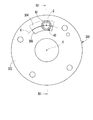
本発明の第一実施形態によるバルブタイミング調整装置を図2及び図3に示す。このバルブタイミング調整装置1は、エンジンの図示しないクランクシャフトの出力トルクをエンジンのカムシャフト2に伝達する伝達系に設けられている。ここでカムシャフト2は回転軸線O周りに回転することで、エンジンの図示しない吸気弁を開閉する。即ちバルブタイミング調整装置1は、作動油の圧力を利用して吸気弁のバルブタイミングを調整するものである。
Hereinafter, a plurality of embodiments showing embodiments of the present invention will be described with reference to the drawings.
(First embodiment)
A valve timing adjusting device according to a first embodiment of the present invention is shown in FIGS. The valve timing adjusting device 1 is provided in a transmission system that transmits output torque of a crankshaft (not shown) of an engine to a
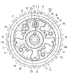
第一回転体10は、四部材が相対回転不能にボルト固定されることによって形成されており、支持軸部11、バックプレート部12、スプロケット部13、周壁部14、シュー15a、15b、15c、15d及びフロントプレート部16を有している。
支持軸部11は円筒状を呈しており、カムシャフト2の外周壁に同軸に支持されてカムシャフト2に対し相対回転可能となっている。バックプレート部12は円環板状を呈しており、支持軸部11の一端部と同軸に且つ一体に形成されている。スプロケット部13は平歯車状を呈しており、バックプレート部12の外周縁部に同軸に嵌合固定されている。スプロケット部13とクランクシャフトとの間には、図示しないチェーンベルトが掛け渡されている。チェーンベルトを通じてクランクシャフトの出力トルクがスプロケット部13に伝達されるとき、第一回転体10はクランクシャフトと連動して図3の時計方向に回転する。
The first
The
周壁部14は円筒状を呈しており、スプロケット部13の一端部と同軸に且つ一体に形成されている。周壁部14から径方向内側に突出するシュー15a、15b、15c、15dは、第一回転体10の回転軸線O周りの周方向に互いに間隔をあけて設けられている。フロントプレート部16は円環板状を呈しており、周壁部14のスプロケット部13とは反対側端部に同軸に固定されている。
The
第二回転体20はベーンロータで構成されており、周壁部14の内周側且つ各プレート部12、16の間において第一回転体10に収容されている。第二回転体20は、固定軸部21及びベーン22a、22b、22c、22dを有している。
固定軸部21は、カムシャフト2に同軸にボルト固定されている。これにより第二回転体20はカムシャフト2と連動して図3の時計方向に回転し、また第一回転体10に対して相対回転可能となっている。第二回転体20は、第一回転体10に対して相対回転するときに各プレート部12、16の内側面17、18及びシュー15a、15b、15c、15dの突出側端面に対して摺動する。
The second
The fixed
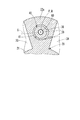
固定軸部21から径方向内側に突出するベーン22a、22b、22c、22dは、第二回転体20の回転軸線O周りの周方向に互いに間隔をあけて設けられている。第二回転体20が第一回転体10に対して相対回転するとき、即ち第二回転体20の位相が変化するときにベーン22a、22b、22c、22dの突出側端面は、周壁部14の内周面に対して摺動する。ベーン22a、22b、22c、22dはそれぞれ所定の二つのシューの間に収容されており、回転軸線O周りの周方向両側に進角油圧室と遅角油圧室とを形成している。具体的には、シュー15aとベーン22aとの間に進角油圧室30が形成され、シュー15bとベーン22bとの間に進角油圧室31が形成され、シュー15cとベーン22cとの間に進角油圧室32が形成され、シュー15dとベーン22dとの間に進角油圧室33が形成されている。また、シュー15dとベーン22aとの間に遅角油圧室34が形成され、シュー15aとベーン22bとの間に遅角油圧室35が形成され、シュー15bとベーン22cの間に遅角油圧室36が形成され、シュー15cとベーン22dとの間に遅角油圧室37が形成されている。
The
進角油圧室30〜33及び遅角油圧室34〜37は、図示しないオイルポンプ及びドレンに連通可能である。進角油圧室30〜33がオイルポンプに連通し、遅角油圧室34〜37がドレンに連通するときには、オイルポンプによって加圧された作動油が進角油圧室30〜33に供給される。この供給油の圧力が各進角油圧室30〜33に面するベーン及びシューへと印加されることによって、第二回転体20の位相が進角側に変化する。また一方、遅角油圧室34〜37がオイルポンプに連通し、進角油圧室30〜33がドレンに連通するときには、オイルポンプによって加圧された作動油が遅角油圧室34〜37に供給される。この供給油の圧力が各遅角油圧室34〜37に面するベーン及びシューに印加されることによって、第二回転体20の位相が遅角側に変化する。
The advance
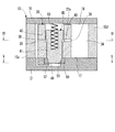
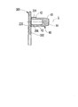
ベーン22aには、支持孔38が回転軸線Oに平行に貫通形成されている。この支持孔38は、バックプレート部12側に向かうほど小径となる段付円筒孔状を呈している。ベーン22aにはさらに、支持孔38の大径側と遅角油圧室34とに連通する連通油路39が貫通形成されている。この連通油路39は、図1及び図4に示すように支持孔38の横断面の接線方向に延伸形成され、支持孔38の中心軸線Pを含む仮想平面Sに対してオフセットされている。
A
図2及び図3に示すように、ロックピン40は有底の円筒状を呈しており、各プレート部12、16の間において支持孔38に同軸に嵌入されている。これによりロックピン40は、第一回転体10に対して第二回転体20と共に相対回転可能となっており、また支持孔38内において回転軸線Oに平行な中心軸線Q方向に往復移動可能且つ当該中心軸線Q周りの周方向に回転可能となっている。ロックピン40は、中心軸線Q方向に並ぶ小径部41及び大径部42を有している。小径部41は、支持孔38の小径側の内周面に対して摺動可能に且つ後述するブッシュ50に対して嵌合可能に形成されている。大径部42は、支持孔38の大径側の内周面に対して摺動可能に形成されている。大径部42において小径部41側の環状端面43は、遅角油圧室34から連通油路39を通じて支持孔38に供給される作動油の圧力を受ける。この受圧によりロックピン40には、バックプレート部12から離間する方向に軸力が作用する。
As shown in FIGS. 2 and 3, the
ブッシュ50は円筒状を呈しており、バックプレート部12の内側面17に開口する凹部に回転軸線Oと平行に圧入固定されている。ブッシュ50の内孔51は、第二回転体20の位相が最遅角位相(図3参照)となるときに小径部41が同軸に嵌合可能な嵌合孔51として機能する。嵌合孔51は、第二回転体20側に向かうほど大径となるテーパ孔状に形成されており、それに合わせて小径部41の先端部も大径部42側に向かうほど大径となるテーパ状に形成されている。バックプレート部12には、嵌合孔51の小径側端部と進角油圧室30とに連通する連通油路52が貫通形成されている。この連通油路52は、図1及び図5に示すように支持孔38の横断面の接線方向に延伸形成され、嵌合孔51の中心軸線Rを含む仮想平面Tに対してオフセットされている。図2に示すように、ブッシュ50において小径部41の端面44は、進角油圧室30から連通油路52を通じて嵌合孔51に供給される作動油の圧力を受ける。この受圧によりロックピン40には、バックプレート部12から離間する方向に軸力が作用する。
The
付勢部材60は圧縮コイルばねで構成されており、ロックピン40とフロントプレート部16との間に介装されている。これにより付勢部材60は、ロックピン40の周方向への回転を阻害しないようにしてロックピン40を軸方向のバックプレート部12側に付勢している。
The urging
次に、バルブタイミング調整装置1の作動について説明する。
エンジンの停止状態ではオイルポンプも停止状態にあるため、油圧室30〜37、支持孔38及び嵌合孔51のいずれにも作動油が供給されず、図2及び図3に示すように第二回転体20の位相が最遅角位相に留められる。これにより、付勢部材60の付勢力を受けるロックピン40が嵌合孔51に嵌合して第二回転体20の位相が最遅角位相にロックされている。
Next, the operation of the valve timing adjusting device 1 will be described.
Since the oil pump is also stopped when the engine is stopped, hydraulic oil is not supplied to any of the
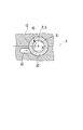
エンジン及びオイルポンプが順次始動すると、進角油圧室30〜33がオイルポンプに、また遅角油圧室34〜37がドレンに連通させられ、加圧された作動油が進角油圧室30〜33へと供給される。このとき、進角油圧室30に作動油が充填されるまでは、付勢部材60の付勢力によってロックピン40が図1の如く嵌合孔51との嵌合状態を保持されて、第二回転体20の位相が最遅角位相にロックされたままとなる。そして、進角油圧室30に作動油が充填されると、当該油圧室30から作動油が連通油路52を経由して嵌合孔51へと導かれる。この嵌合孔51に導かれた作動油の圧力はロックピン40の小径部41側の端面44に作用することから、当該圧力による軸力が付勢部材60の付勢力に打ち勝つと、図6の如くロックピン40がバックプレート部12に対する離間方向へと移動する。この移動によりロックピン40が図6(B)の如く嵌合孔51から抜出することで、第二回転体20の位相ロックが解除され、その結果、第二回転体20の位相変化が許容されることとなる。さらに本実施形態では、嵌合孔51の中心軸線Rを含む仮想平面Tに対して連通油路52がオフセット形成されているので、ロックピン40が同軸嵌合する嵌合孔51への導入油は、図5の白抜矢印の如くロックピン40の周方向に旋回するようにして流動する。このような旋回流の発生により、少なくともロックピン40が嵌合孔51から抜出するまでの間、周方向の回転モーメントがロックピン40に作用する。
When the engine and the oil pump are sequentially started, the advance
この後、エンジンの運転状態に応じて、オイルポンプ及びドレンにそれぞれ連通する油圧室が遅角油圧室34〜37と進角油圧室30〜33との間で切り換えられることにより、第二回転体20の位相ひいてはバルブタイミングが調整される。ここで、遅角油圧室34〜37がオイルポンプに連通させられるときには、遅角油圧室34に供給、充填された作動油が、さらに連通油路39を経由して支持孔38へと導かれることとなる。この支持孔38に導かれた作動油の圧力は大径部42の環状端面43に作用するため、ロックピン40が嵌合孔51と同軸上に位置するときには、ロックピン40を嵌合孔51との非嵌合位置に移動させておくことが可能となる。さらに本実施形態では、支持孔38の中心軸線Pを含む仮想平面Sに対して連通油路39がオフセット形成されているので、ロックピン40を同軸支持する支持孔38への導入油は、図4の白抜矢印の如くロックピン40の周方向に旋回するようにして流動する。ここで支持孔38への導入油の旋回方向は、嵌合孔51への導入油の旋回方向とは逆向きとなっているが、嵌合孔51への導入油の旋回方向と同じ向きであってもよい。このような旋回流の発生により、少なくとも遅角油圧室34がオイルポンプに連通する間、周方向の回転モーメントがロックピン40に作用する。尚、第二回転体20の位相変化時においてロックピン40は、吸気弁から第二回転体20への伝達トルクが変動することにより環状端面43への作用圧力が変動することに起因して、図7の如くプレート部12、16の内側面17、18のいずれかに対して摺動する。
Thereafter, the hydraulic chambers communicating with the oil pump and the drain are switched between the retard
以上説明したように、エンジンの始動直後における第二回転体20の位相ロック時には進角油圧室30から嵌合孔51への導入油が、また第二回転体20の位相変化時には遅角油圧室34から支持孔38への導入油が、ロックピン40の周方向の旋回流となる。したがって、第二回転体20の位相ロック時及び位相変化時の双方において、ロックピン40に回転モーメントを作用させて当該ロックピン40を周方向に回転させることができる。故に、エンジンの始動後、ロックピン40が嵌合孔51から抜出する前に第二回転体20の位相が変化してロックピン40及び嵌合孔51に摩耗が生じることがあっても、ロックピン40が回転することで、当該磨耗が特定箇所に集中する事態を回避することができる。しかも、各油圧室30、34から各孔51、38への導入油は、旋回流の発生機能のみならず、ロックピン40を嵌合孔51との非嵌合位置に移動させる機能をも果たすことができる。このような機能の集約によれば、低コスト化及び小型化を図ることができる。
As described above, the oil introduced from the advance
以上、第一実施形態では、クランクシャフトが特許請求の範囲に記載の「駆動軸」に相当し、カムシャフト2が特許請求の範囲に記載の「従動軸」に相当する。また、進角油圧室30が特許請求の範囲に記載の「流体室」及び「第一流体室」に相当し、遅角油圧室34が特許請求の範囲に記載の「第二流体室」に相当する。さらに、ロックピン40が特許請求の範囲に記載の「ロック部材」に相当し、連通油路52が特許請求の範囲に記載の「連通路」及び「第一連通路」に相当し、連通油路39が特許請求の範囲に記載の「第二連通路」に相当する。
As described above, in the first embodiment, the crankshaft corresponds to the “drive shaft” recited in the claims, and the
(第二実施形態)
図8に示すように、本発明の第二実施形態は第一実施形態の変形例であり、第一実施形態と実質的に同一の構成部分には同一の符号を付すことで説明を省略する。
第二実施形態では、ロックピン100の小径部102に二種類の凹部104、106が設けられている。
(Second embodiment)
As shown in FIG. 8, the second embodiment of the present invention is a modification of the first embodiment, and the description of the components that are substantially the same as those of the first embodiment will be omitted by attaching the same reference numerals. .
In the second embodiment, two types of
具体的に第一凹部104は、ロックピン100の周方向において等間隔に四つ設けられ、ロックピン100の中心軸線Q上において互いに連結されている。各第一凹部104は、小径部102の端面108に開口し且つロックピン100の径方向に延伸する溝状に形成されている。各第一凹部104の側面110は、中心軸線Qを含む仮想平面X又はYの法線方向を向いている。
Specifically, four
第二凹部106は、ロックピン100の周方向において等間隔に四つ設けられている。各第二凹部106は、小径部102の外周面112に開口し且つ中心軸線Qに沿って延伸する溝状に形成されている。各第二凹部106の側面114は、中心軸線Qを含む仮想平面X又はYの法線方向を向いている。
Four
このような第二実施形態によると、各第一凹部104の側面110は、ロックピン100が挿入された嵌合孔51から各第一凹部104に旋回流が進入した場合に当該旋回流を遮るように位置する。したがって、第二回転体20の位相ロック時には、各第一凹部104の側面110に旋回流が衝突することで、より大きな回転モーメントがロックピン100に与えられることとなる。
According to the second embodiment, the
また、第二実施形態によると、各第二凹部106の側面114は、支持孔38から各第二凹部106に旋回流が進入した場合に当該旋回流を遮るように位置する。したがって、第二回転体20の位相変化時には、各第二凹部106の側面114に旋回流が衝突することで、より大きな回転モーメントがロックピン100に与えられることとなる。
Further, according to the second embodiment, the
このように第二実施形態によれば、第二回転体20の位相ロック時及び位相変化時の双方においてロックピン100の回転が促進されてその回転角度が増大するので、ロックピン100及び嵌合孔51における磨耗集中の回避効果を高めることができる。
以上、第二実施形態では、ロックピン100が特許請求の範囲に記載の「ロック部材」に相当し、小径部102の端面108及び外周面112が特許請求の範囲に記載の「外面」に相当する。
As described above, according to the second embodiment, since the rotation of the
As described above, in the second embodiment, the
(第三実施形態)
図9に示すように、本発明の第三実施形態は第一実施形態の変形例であり、第一実施形態と実質的に同一の構成部分には同一の符号を付すことで説明を省略する。
第三実施形態では、ロックピン150の小径部152に二種類の突部154、156が設けられている。
(Third embodiment)
As shown in FIG. 9, the third embodiment of the present invention is a modification of the first embodiment, and the description of the components that are substantially the same as those of the first embodiment will be omitted by attaching the same reference numerals. .
In the third embodiment, two types of
具体的に第一突部154は、ロックピン150の周方向において等間隔に四つ設けられ、ロックピン150の中心軸線Q上において互いに連結されている。各第一突部154は、小径部152の端面158から突出し且つロックピン150の径方向に延伸する突条形態に形成されている。各第一突部154の側面160は、中心軸線Qを含む仮想平面XはYの法線方向を向いている。
Specifically, four
第二突部156は、ロックピン150の周方向において等間隔に四つ設けられている。各第二突部156は、小径部152の外周面162から突出し且つ中心軸線Qに沿って延伸する突条形態に形成されている。各第二突部156の側面164は、中心軸線Qを含む仮想平面X又はYの法線方向を向いている。
Four
このような第三実施形態によると、各第一突部154の側面160は、ロックピン150が挿入された嵌合孔51に旋回流が発生した場合に当該旋回流を遮るように位置する。したがって、第二回転体20の位相ロック時には、各第一突部154の側面160に旋回流が衝突することで、より大きな回転モーメントがロックピン150に与えられることとなる。
According to the third embodiment, the
また、第三実施形態によると、各第二突部156の側面164は、支持孔38に旋回流が発生した場合に当該旋回流を遮るように位置する。したがって、第二回転体20の位相変化時には、各第二突部156の側面164に旋回流が衝突することで、より大きな回転モーメントがロックピン150に与えられることとなる。
Further, according to the third embodiment, the
このように第三実施形態によれば、第二回転体20の位相ロック時及び位相変化時の双方においてロックピン150の回転が促進されてその回転角度が増大するので、ロックピン150及び嵌合孔51における磨耗集中の回避効果を高めることができる。
以上、第二実施形態では、ロックピン150が特許請求の範囲に記載の「ロック部材」に相当し、小径部152の端面158及び外周面162が特許請求の範囲に記載の「外面」に相当する。
Thus, according to the third embodiment, since the rotation of the
As described above, in the second embodiment, the
(第四実施形態)
図10〜図12に示すように、本発明の第四実施形態は第一実施形態の変形例であり、第一実施形態と実質的に同一の構成部分には同一の符号を付すことで説明を省略する。
第四実施形態では、連通油路39、52に代えて、各孔38、51の径方向軸線上を延伸する連通油路200、202が設けられている。さらに第四実施形態では、フロントプレート部212において第二回転体20の位相変化時にロックピン40が摺動する内側面214に、二種類の摺接面216、218が設けられている。
(Fourth embodiment)
As shown in FIGS. 10-12, 4th embodiment of this invention is a modification of 1st embodiment, and it demonstrates by attaching | subjecting the same code | symbol to the component substantially the same as 1st embodiment. Is omitted.
In the fourth embodiment, instead of the
具体的に第一摺接面216は、回転軸線Oを中心とする仮想円弧Aの径方向内側において、仮想円弧Aに隣接して沿う帯状に設定されている。ここで仮想円弧Aは、第二回転体20の位相変化時にロックピン40の中心軸線Qが当該仮想円弧A上を通過することを示すために仮想的に定義したものである。したがって、第二回転体20の位相が変化するとき第一摺接面216は、ロックピン40の大径部42側の端面220において仮想円弧Aの径方向内側部分に摺接する。尚、図11において第一摺接面216を一点鎖線で囲んで示しているのは、本実施形態において第一摺接面216の表面状態が、内側面214の摺接面216、218を除く部分の表面状態と略等しくされているからである。
Specifically, the first sliding
第二摺接面218は、仮想円弧Aの径方向外側、即ちここでは第一摺接面216の径方向外側において仮想円弧Aに隣接して沿う帯状に形成されている。これにより、第二回転体20の位相が変化するとき第二摺接面218は、ロックピン40の端面220において仮想円弧Aの径方向外側部分に摺接する。本実施形態において第二摺接面218にはブラスト処理等の表面処理が施されており、それによって第二摺接面218の摩擦係数と第一摺接面216の摩擦係数とが相異させられている。尚、第二摺接面218の摩擦係数については、第一摺接面216の摩擦係数よりも大きくしてもよいし、小さくしてもよい。
The second sliding
このような第四実施形態では、エンジンの始動後に第二回転体20の位相を変化させる際、ロックピン40とフロントプレート部212との摺動界面に摩擦力が働く。このとき、仮想円弧Aの径方向内側では第一摺接面216がロックピン40の端面220に摺接し、仮想円弧Aの径方向外側では第二摺接面218が端面220に摺接する。そのため、ロックピン40とフロントプレート部212との摺動界面において仮想円弧Aを挟んだ両側では、摺接面216、218間の摩擦係数差に応じて摩擦力の大きさが相異することとなる。これによりロックピン40では、中心軸線Qを挟む両側において作用力のバランスが崩れるため、周方向の回転モーメントが生じる。尚、ここで回転モーメントの方向は、第二回転体20の位相遅角時と位相進角時とで反対となる。
In such a fourth embodiment, when the phase of the second
したがって、第四実施形態によれば、第二回転体20の位相変化によってバルブタイミングを調整しつつ、ロックピン40を周方向に回転させることができる。故に、エンジンの始動後、ロックピン40が嵌合孔51から抜出する前に第二回転体20の位相が変化してロックピン40及び嵌合孔51に摩耗が生じることがあっても、ロックピン40が回転することで、当該磨耗が特定箇所に集中する事態を回避することができる。
Therefore, according to the fourth embodiment, the
さらに第四実施形態では、フロントプレート部212に対して摺動するロックピン40には、環状端面43への作用圧力による軸力と付勢部材60の付勢力とが作用する。ここで前者の軸力は、第二回転体20の位相遅角時には、遅角油圧室34から支持孔38への導入油の圧力によって増大する一方、第二回転体20の位相進角時には、支持孔38から遅角油圧室34に作動油が戻されることによって減少する。故に、第二回転体20の位相遅角時と位相進角時とでは、ロックピン40とフロントプレート部212との摺動界面に働く摩擦力の大きさ、ひいてはロックピン40に作用する回転モーメントの大きさに違いが生じる。しかも、吸気弁から第二回転体20への伝達トルクが変動することにより環状端面43への作用圧力が変動することに起因して、ロックピン40がフロントプレート部212から離間することもあり、その場合には回転モーメントがロックピン40に作用しなくなる。以上より、第二回転体20の位相を遅角側と進角側とに交互に変化させるようにした場合でも、一方側への位相変化時に回転したロックピン40が他方側への位相変化時に元の位置へと戻ることを防止できるので、上述した磨耗集中の回避効果を十分に得ることができる。
Furthermore, in the fourth embodiment, the axial force due to the acting pressure on the
以上、第四実施形態において第一摺接面216は、仮想円弧Aの径方向内側たる第二摺接面218の径方向内側に設定されているとも考えることができるので、第一摺接面216及び第二摺接面218は特許請求の範囲の請求項11、12に記載の「内側摺接面」及び「外側摺接面」にそれぞれ相当する。
As described above, in the fourth embodiment, the first sliding
(第五実施形態)
図13に示すように、本発明の第五実施形態は第四実施形態の変形例であり、第四実施形態と実質的に同一の構成部分には同一の符号を付すことで説明を省略する。
第五実施形態では、仮想円弧Aの径方向外側において第二摺接面250が、仮想円弧Aに間隔をあけて沿う帯状に形成されている。これにより、第二回転体20の位相が変化するとき第二摺接面250は、ロックピン40の大径部42側の端面220において仮想円弧Aよりも径方向外側に位置する部分に摺接する。また、第一摺接面252は、仮想円弧Aの径方向内側を含む第二摺接面250の径方向内側において第二摺接面250に隣接して沿う帯状に設定されている。これにより、第二回転体20の位相が変化するとき第一摺接面252は、ロックピン40の端面220において仮想円弧Aを径方向に跨ぐ部分に摺接する。
(Fifth embodiment)
As shown in FIG. 13, the fifth embodiment of the present invention is a modification of the fourth embodiment, and the description of the components that are substantially the same as those of the fourth embodiment will be omitted by attaching the same reference numerals. .
In the fifth embodiment, the second
このような第五実施形態では、第二回転体20の位相変化時において、仮想円弧Aの径方向外側では第一及び第二摺接面252、250の双方がロックピン40の端面220に摺接し、仮想円弧Aの径方向内側では第一摺接面252のみが端面220に摺接する。そのため、ロックピン40とフロントプレート部254の内側面256との摺動界面において仮想円弧Aを挟んだ両側では、摺接面252、250間の摩擦係数差に応じて摩擦力の大きさが相異することとなる。したがって、第四実施形態と同様な原理によりロックピン40を周方向に回転させて、当該ロックピン40及び嵌合孔51における特定箇所に磨耗が集中する事態を回避することができる。
以上、第五実施形態では、第一摺接面252及び第二摺接面250が特許請求の範囲の請求項12に記載の「内側摺接面」及び「外側摺接面」にそれぞれ相当する。
In the fifth embodiment, when the phase of the second
As described above, in the fifth embodiment, the first
尚、図14の変形例の如く、仮想円弧Aの径方向内側で仮想円弧Aに間隔をあけて沿う帯状に第一摺接面252を設定し、且つ仮想円弧Aの径方向外側を含む第一摺接面252の径方向外側で第一摺接面252に隣接して沿う帯状に第二摺接面250を形成してもよい。この場合、第一摺接面252及び第二摺接面250が特許請求の範囲の請求項11に記載の「内側摺接面」及び「外側摺接面」にそれぞれ相当する。
14, the first sliding
(第六実施形態)
図15及び図16に示すように、本発明の第六実施形態は第四実施形態の変形例であり、第四実施形態と実質的に同一の構成部分には同一の符号を付すことで説明を省略する。
第六実施形態では、フロントプレート部300に摺接面304及び対向孔306が設けられている。
(Sixth embodiment)
As shown in FIGS. 15 and 16, the sixth embodiment of the present invention is a modification of the fourth embodiment, and components that are substantially the same as those of the fourth embodiment are denoted by the same reference numerals. Is omitted.
In the sixth embodiment, the
具体的に摺接面304はフロントプレート部300の内側面302の一部からなり、仮想円弧Aの径方向外側において仮想円弧Aに隣接して沿う帯状に設定されている。したがって、第二回転体20の位相が変化するとき摺接面304は、ロックピン40の大径部42側の端面220において仮想円弧Aの径方向外側部分に摺接する。尚、図15において摺接面304を一点鎖線で囲んで示しているのは、第四実施形態の第一摺接面216の場合と同様な理由による。
Specifically, the
対向孔306は、内側面302に開口する有底孔からなり、仮想円弧Aの径方向内側、即ちここでは摺接面304の径方向内側において仮想円弧Aに隣接して沿う帯状に形成されている。これにより、第二回転体20の位相が変化するとき対向孔306の開口は、ロックピン40の端面220において仮想円弧Aの径方向内側部分と対向する。
The
このような第六実施形態では、第二回転体20の位相変化時において、仮想円弧Aの径方向外側ではロックピン40の端面220が内側面302の摺接面304に摺接し、仮想円弧Aの径方向内側では端面220が内側面302に全く摺接しない。そのため、ロックピン40とフロントプレート部300との摺動界面において、仮想円弧Aの径方向外側では摩擦力が発生するが、仮想円弧Aの径方向内側では摩擦力が0となる。要するに、仮想円弧Aを挟んだ両側では、摺接の有無に起因して摩擦力の大きさが相異することとなる。したがって、第四実施形態と同様な原理によりロックピン40を周方向に回転させて、当該ロックピン40及び嵌合孔51における特定箇所に磨耗が集中する事態を回避することができる。
In such a sixth embodiment, when the phase of the second
以上、第六実施形態において摺接面304は、仮想円弧Aの径方向外側たる対向孔306の径方向外側に設定されているとも考えることができるので、摺接面304及び対向孔306は特許請求の範囲の請求項13、14に記載の「摺接面」及び「対向孔」にそれぞれ相当する。
As described above, in the sixth embodiment, the
尚、図17の変形例の如く、仮想円弧Aの径方向内側で仮想円弧Aに隣接して沿う帯状に摺接面304を設定し、且つ仮想円弧Aの径方向外側たる摺接面304の径方向外側で仮想円弧Aに隣接して沿う帯状に対向孔306を形成してもよい。この場合、摺接面304は、仮想円弧Aの径方向内側たる対向孔306の径方向内側に設定されているとも考えることができるので、摺接面304及び対向孔306は特許請求の範囲の請求項15、16に記載の「摺接面」及び「対向孔」にそれぞれ相当する。
17, the sliding
(第七実施形態)
図18に示すように、本発明の第七実施形態は第六実施形態の変形例であり、第六実施形態と実質的に同一の構成部分には同一の符号を付すことで説明を省略する。
第七実施形態では、仮想円弧Aの径方向外側において摺接面350が、仮想円弧Aに間隔をあけて沿う帯状に設定されている。これにより、第二回転体20の位相が変化するとき摺接面350は、ロックピン40の大径部42側の端面220において仮想円弧Aよりも径方向外側に位置する部分に摺接する。また、対向孔352は、仮想円弧Aの径方向内側を含む摺接面350の径方向内側において摺接面350に隣接して沿う帯状に形成されている。これにより、第二回転体20の位相が変化するとき対向孔352の開口は、ロックピン40の端面220において仮想円弧Aを径方向に跨ぐ部分と対向する。
(Seventh embodiment)
As shown in FIG. 18, the seventh embodiment of the present invention is a modification of the sixth embodiment, and the description of the components that are substantially the same as those of the sixth embodiment will be omitted by attaching the same reference numerals. .
In the seventh embodiment, the
このような第七実施形態によれば、第六実施形態と同様な作用、効果が得られる。
以上、摺接面350及び対向孔352が特許請求の範囲の請求項13に記載の「摺接面」及び「対向孔」にそれぞれ相当する。
尚、図19の変形例の如く、仮想円弧Aの径方向内側で仮想円弧Aに間隔をあけて沿う帯状に摺接面350を設定し、且つ仮想円弧Aの径方向外側を含む摺接面350の径方向外側で摺接面350に隣接して沿う帯状に対向孔352を形成してもよい。この場合、摺接面350及び対向孔352が特許請求の範囲の請求項15に記載の「摺接面」及び「対向孔」にそれぞれ相当する。
According to such 7th embodiment, the effect | action and effect similar to 6th embodiment are acquired.
As described above, the
19, the sliding
(第八実施形態)
図20に示すように、本発明の第八実施形態は第六実施形態の変形例であり、第六実施形態と実質的に同一の構成部分には同一の符号を付すことで説明を省略する。
第八実施形態では、仮想円弧Aの径方向内側において対向孔400が、仮想円弧Aに間隔をあけて沿う帯状に形成されている。これにより、第二回転体20の位相が変化するとき対向孔400は、ロックピン40の大径部42側の端面220において仮想円弧Aよりも径方向内側に位置する部分と対向する。また、摺接面402は、仮想円弧Aの径方向外側を含む対向孔400の径方向外側において対向孔400に隣接して沿う帯状に設定されている。これにより、第二回転体20の位相が変化するとき摺接面402は、ロックピン40の端面220において仮想円弧Aを径方向に跨ぐ部分に摺接する。
(Eighth embodiment)
As shown in FIG. 20, the eighth embodiment of the present invention is a modification of the sixth embodiment, and the description of the components that are substantially the same as those of the sixth embodiment will be omitted by retaining the same reference numerals. .
In the eighth embodiment, the opposing
このような第八実施形態では、第二回転体20の位相変化時において、ロックピン40の端面220と摺接面402との摺接面積が仮想円弧Aの両側で相異する。そのため、ロックピン40とフロントプレート部404の内側面406との摺動界面において仮想円弧Aを挟んだ両側では、摺接面積の違いに起因して摩擦力の大きさが相異することとなる。したがって、第四実施形態で説明した原理と同様な原理によりロックピン40を周方向に回転させて、当該ロックピン40及び嵌合孔51における特定箇所に磨耗が集中する事態を回避することができる。
以上、第八実施形態では、対向孔400及び摺接面402が特許請求の範囲の請求項14に記載の「対向孔」及び「摺接面」にそれぞれ相当する。
In the eighth embodiment, the sliding contact area between the
As described above, in the eighth embodiment, the facing
尚、図21の変形例の如く、仮想円弧Aの径方向外側で仮想円弧Aに間隔をあけて沿う帯状に対向孔400を形成し、且つ仮想円弧Aの径方向内側を含む対向孔400の径方向内側で対向孔400に隣接して沿う帯状に摺接面402を設定してもよい。この場合、対向孔400及び摺接面402が特許請求の範囲の請求項16に記載の「対向孔」及び「摺接面」にそれぞれ相当する。
21, the opposing
以上、本発明の複数の実施形態について説明したが、本発明はそれらの実施形態に限定して解釈されるものではない。
例えば第一〜第八実施形態では、エンジンの始動直後、まず、遅角油圧室34〜37をオイルポンプに連通させて連通油路39から支持孔38への導入油の圧力によりロックピン40を嵌合孔51から抜出させた後、バルブタイミング調整を行うようにしてもよい。
Although a plurality of embodiments of the present invention have been described above, the present invention should not be construed as being limited to those embodiments.
For example, in the first to eighth embodiments, immediately after the engine is started, the retard
さらに第一〜第三実施形態では、各孔38、51の軸方向や周方向に複数並ぶ形態で連通油路39、52を設けるようにしてもよいし、あるいは連通油路52のみを設けるようにしてもよい。また、第二実施形態では、凹部104、106の配設数を適宜設定可能であり、例えば凹部104、106の一方を設けないようにしてもよい。さらにまた、第三実施形態では、突部154、156の配設数を適宜設定可能であり、例えば突部154、156の一方を設けないようにしてもよい。
Furthermore, in the first to third embodiments, the
またさらに第四及び第五実施形態では、第一摺接面216、252及び第二摺接面218、250の双方に表面処理による摩擦係数調整を施すようにしてもよいし、第一摺接面216、252のみに表面処理による摩擦係数調整を施すようにしてもよい。また、第六〜第八実施形態では、表面処理による摩擦係数調整を摺接面304、350、402に施すようにしてもよい。
Furthermore, in the fourth and fifth embodiments, the first sliding
1 バルブタイミング調整装置、2 カムシャフト(従動軸)、10 第一回転体、12 バックプレート部、16、212、254、300、404 フロントプレート部、18、214、256、302、406 内側面、20 第二回転体、30 進角油圧室(流体室、第一流体室)、34 遅角油圧室(第二流体室)、38 支持孔、39 連通油路(第二連通路)、40、100、150 ロックピン(ロック部材)、41、102、152 小径部、42 大径部、43 環状端面、50 ブッシュ、51 嵌合孔、52 連通油路(連通路、第一連通路)、60 付勢部材、104 第一凹部(凹部)、106 第二凹部(凹部)、108 端面(外面)、110、114 側面、112 外周面(外面)、154 第一突部(突部)、156 第二突部(突部)、158 端面(外面)、160、164 側面、162 外周面(外面)、200、202 連通油路、216、252 第一摺接面(内側摺接面)、218、250 第二摺接面(外側摺接面)、220 端面、304、350、402 摺接面、306、352、400 対向孔、A 仮想円弧、O 回転軸線、Q 中心軸線、S、T、X、Y 仮想平面 DESCRIPTION OF SYMBOLS 1 Valve timing adjustment apparatus, 2 Camshaft (driven shaft), 10 1st rotary body, 12 Back plate part, 16, 212, 254, 300, 404 Front plate part, 18, 214, 256, 302, 406 Inner side surface, 20 second rotating body, 30 advance hydraulic chamber (fluid chamber, first fluid chamber), 34 retard hydraulic chamber (second fluid chamber), 38 support hole, 39 communicating oil passage (second communicating passage), 40, 100, 150 Lock pin (lock member), 41, 102, 152 Small diameter part, 42 Large diameter part, 43 Annular end face, 50 Bush, 51 Fitting hole, 52 Communication oil path (communication path, first series path), 60 Urging member, 104 first recess (recess), 106 second recess (recess), 108 end surface (outer surface), 110, 114 side surface, 112 outer peripheral surface (outer surface), 154 first protrusion (projection), 156 Second projecting portion (projecting portion), 158 End surface (outer surface), 160, 164 Side surface, 162 Outer peripheral surface (outer surface), 200, 202 Communicating oil passage, 216, 252 First sliding contact surface (inner sliding contact surface), 218 250, second sliding contact surface (outer sliding contact surface), 220 end surface, 304, 350, 402 sliding contact surface, 306, 352, 400 facing hole, A virtual arc, O rotation axis, Q center axis, S, T, X, Y virtual plane
Claims (16)
嵌合孔を有し、前記駆動軸及び前記従動軸の一方に連動して回転軸線周りに回転する第一回転体と、
前記第一回転体に収容されて前記第一回転体との間に流体室を形成し、前記駆動軸及び前記従動軸の他方に連動して前記回転軸線周りに回転し、前記流体室の流体圧力により前記第一回転体に対して相対回転する第二回転体と、
前記第二回転体に支持されて前記回転軸線に平行な中心軸線方向に往復移動可能且つ当該中心軸線周りの周方向に回転可能であり、前記嵌合孔との嵌合位置に移動することにより前記第二回転体の前記第一回転体に対する相対回転位相をロックし、前記嵌合孔との非嵌合位置に移動することにより前記相対回転位相の変化を許容するロック部材と、
前記流体室及び前記嵌合孔に連通し、前記流体室の流体を前記嵌合孔に導くことにより前記ロック部材の前記周方向に旋回流を発生させる連通路と、
を備えることを特徴とするバルブタイミング調整装置。 A valve timing adjusting device that is provided in a transmission system that transmits output torque of a drive shaft of an internal combustion engine to a driven shaft that opens and closes at least one of an intake valve and an exhaust valve, and adjusts the opening and closing timing of at least one of the valves,
A first rotating body having a fitting hole and rotating around a rotation axis in conjunction with one of the drive shaft and the driven shaft;
A fluid chamber is formed between the first rotating body and the first rotating body, and rotates around the rotation axis in conjunction with the other of the drive shaft and the driven shaft. A second rotating body that rotates relative to the first rotating body by pressure;
By being supported by the second rotating body and reciprocally movable in a central axis direction parallel to the rotational axis, and rotatable in a circumferential direction around the central axis, and moved to a fitting position with the fitting hole A locking member that locks the relative rotational phase of the second rotating body with respect to the first rotating body and allows the change of the relative rotational phase by moving to a non-fitting position with the fitting hole;
A communication path that communicates with the fluid chamber and the fitting hole, and generates a swirling flow in the circumferential direction of the lock member by guiding the fluid in the fluid chamber to the fitting hole;
A valve timing adjusting device comprising:
前記第一流体室及び前記嵌合孔に連通し、前記第一流体室の流体を前記嵌合孔に導くことにより前記ロック部材の前記周方向に旋回流を発生させる前記連通路としての第一連通路と、
前記第二流体室及び前記支持孔に連通し、前記第二流体室の流体を前記支持孔に導くことにより前記ロック部材の前記周方向に旋回流を発生させる第二連通路と、
を備えることを特徴とする請求項1〜3のいずれか一項に記載のバルブタイミング調整装置。 The second rotating body having a support hole for supporting the lock member and forming a first fluid chamber and a second fluid chamber with the first rotating body;
A first communication path that communicates with the first fluid chamber and the fitting hole and generates a swirling flow in the circumferential direction of the lock member by guiding the fluid in the first fluid chamber to the fitting hole. A communication path,
A second communication path that communicates with the second fluid chamber and the support hole, and that generates a swirling flow in the circumferential direction of the lock member by guiding the fluid in the second fluid chamber to the support hole;
The valve timing adjusting device according to any one of claims 1 to 3, further comprising:
嵌合孔を有し、前記駆動軸及び前記従動軸の一方に連動して回転軸線周りに回転する第一回転体と、
前記第一回転体に収容されて前記第一回転体との間に流体室を形成し、前記駆動軸及び前記従動軸の他方に連動して前記回転軸線周りに回転し、前記流体室の流体圧力により前記第一回転体に対して相対回転する第二回転体と、
前記第二回転体に支持されて前記回転軸線に平行な中心軸線方向に往復移動可能且つ当該中心軸線周りの周方向に回転可能であり、前記嵌合孔との嵌合位置に移動することにより前記第二回転体の前記第一回転体に対する相対回転位相をロックし、前記嵌合孔との非嵌合位置に移動することにより前記相対回転位相の変化を許容するロック部材と、
を備え、
前記相対回転位相が変化するとき、前記回転軸線周りの仮想円弧上を前記中心軸線が通過するように前記ロック部材が前記第一回転体に対して摺動し、当該摺動界面に働く摩擦力の大きさが前記仮想円弧を挟む両側において相異することを特徴とするバルブタイミング調整装置。 A valve timing adjusting device that is provided in a transmission system that transmits output torque of a drive shaft of an internal combustion engine to a driven shaft that opens and closes at least one of an intake valve and an exhaust valve, and adjusts the opening and closing timing of at least one of the valves,
A first rotating body having a fitting hole and rotating around a rotation axis in conjunction with one of the drive shaft and the driven shaft;
A fluid chamber is formed between the first rotating body and the first rotating body, and rotates around the rotation axis in conjunction with the other of the drive shaft and the driven shaft. A second rotating body that rotates relative to the first rotating body by pressure;
By being supported by the second rotating body and reciprocally movable in a central axis direction parallel to the rotational axis, and rotatable in a circumferential direction around the central axis, and moved to a fitting position with the fitting hole A locking member that locks the relative rotational phase of the second rotating body with respect to the first rotating body and allows the change of the relative rotational phase by moving to a non-fitting position with the fitting hole;
With
When the relative rotational phase changes, the lock member slides relative to the first rotating body so that the central axis passes through a virtual arc around the rotational axis, and a frictional force acting on the sliding interface The valve timing adjusting device is characterized in that the sizes of the two are different on both sides of the virtual arc.
前記内側摺接面と前記外側摺接面とには、相異なる摩擦係数が設定されることを特徴とする請求項10に記載のバルブタイミング調整装置。 The first rotating body includes an inner sliding contact surface that is provided radially inward of the virtual arc and slides in contact with an end surface of the lock member when the relative rotational phase changes, and the inner side includes the radial outer side of the virtual arc. An outer slidable contact surface that is provided on the radially outer side of the slidable contact surface and slidably contacts the end surface when the relative rotational phase changes,
The valve timing adjusting device according to claim 10, wherein different friction coefficients are set for the inner sliding surface and the outer sliding surface.
前記外側摺接面と前記内側摺接面とには、相異なる摩擦係数が設定されることを特徴とする請求項10に記載のバルブタイミング調整装置。 The first rotating body is provided on an outer side in the radial direction of the virtual arc, and includes an outer sliding contact surface that is in sliding contact with an end surface of the lock member when the relative rotational phase changes, and the outer side including the inner side in the radial direction of the virtual arc. An inner sliding surface that is provided on the radially inner side of the sliding surface and that is in sliding contact with the end surface when the relative rotational phase changes,
The valve timing adjusting device according to claim 10, wherein different friction coefficients are set for the outer sliding surface and the inner sliding surface.
Priority Applications (1)
| Application Number | Priority Date | Filing Date | Title |
|---|---|---|---|
| JP2004380658A JP2006183631A (en) | 2004-12-28 | 2004-12-28 | Valve timing adjustment device |
Applications Claiming Priority (1)
| Application Number | Priority Date | Filing Date | Title |
|---|---|---|---|
| JP2004380658A JP2006183631A (en) | 2004-12-28 | 2004-12-28 | Valve timing adjustment device |
Publications (1)
| Publication Number | Publication Date |
|---|---|
| JP2006183631A true JP2006183631A (en) | 2006-07-13 |
Family
ID=36736900
Family Applications (1)
| Application Number | Title | Priority Date | Filing Date |
|---|---|---|---|
| JP2004380658A Pending JP2006183631A (en) | 2004-12-28 | 2004-12-28 | Valve timing adjustment device |
Country Status (1)
| Country | Link |
|---|---|
| JP (1) | JP2006183631A (en) |
Cited By (5)
| Publication number | Priority date | Publication date | Assignee | Title |
|---|---|---|---|---|
| JP2008202438A (en) * | 2007-02-17 | 2008-09-04 | Hosei Brake Ind Ltd | Variable valve timing mechanism for engine |
| JP2010190144A (en) * | 2009-02-19 | 2010-09-02 | Denso Corp | Valve timing adjusting device and method for manufacturing the same |
| JP2011169313A (en) * | 2010-01-20 | 2011-09-01 | Denso Corp | Valve timing adjustment device |
| JP2012047061A (en) * | 2010-08-24 | 2012-03-08 | Denso Corp | Valve timing adjusting device |
| WO2017119234A1 (en) * | 2016-01-07 | 2017-07-13 | 日立オートモティブシステムズ株式会社 | Internal-combustion engine valve timing control device |
-
2004
- 2004-12-28 JP JP2004380658A patent/JP2006183631A/en active Pending
Cited By (9)
| Publication number | Priority date | Publication date | Assignee | Title |
|---|---|---|---|---|
| JP2008202438A (en) * | 2007-02-17 | 2008-09-04 | Hosei Brake Ind Ltd | Variable valve timing mechanism for engine |
| JP2010190144A (en) * | 2009-02-19 | 2010-09-02 | Denso Corp | Valve timing adjusting device and method for manufacturing the same |
| JP2011169313A (en) * | 2010-01-20 | 2011-09-01 | Denso Corp | Valve timing adjustment device |
| US8863709B2 (en) | 2010-01-20 | 2014-10-21 | Denso Corporation | Valve timing adjuster |
| JP2012047061A (en) * | 2010-08-24 | 2012-03-08 | Denso Corp | Valve timing adjusting device |
| CN102373980A (en) * | 2010-08-24 | 2012-03-14 | 株式会社电装 | Valve timing control apparatus |
| US9309789B2 (en) | 2010-08-24 | 2016-04-12 | Denso Corporation | Valve timing control apparatus |
| WO2017119234A1 (en) * | 2016-01-07 | 2017-07-13 | 日立オートモティブシステムズ株式会社 | Internal-combustion engine valve timing control device |
| CN108368754A (en) * | 2016-01-07 | 2018-08-03 | 日立汽车系统株式会社 | The valve timing control device of internal combustion engine |
Similar Documents
| Publication | Publication Date | Title |
|---|---|---|
| JP2012057578A (en) | Valve timing control device | |
| JP2010196698A (en) | Valve opening/closing timing control device | |
| JP2011169215A (en) | Control valve apparatus | |
| WO1999049187A1 (en) | Valve timing control device of internal combustion engine | |
| US6647936B2 (en) | VCT lock pin having a tortuous path providing a hydraulic delay | |
| KR101679016B1 (en) | Apparatus of adjusting valve timing for internal combustion engine | |
| JP2007023953A (en) | Valve timing adjustment device | |
| JP2009068448A (en) | Valve timing adjusting device | |
| JP4487263B2 (en) | Valve timing adjustment device | |
| JP2006125318A (en) | Valve timing adjusting device | |
| JP2006183631A (en) | Valve timing adjustment device | |
| JP2015045282A (en) | Valve opening/closing timing control device | |
| JP2005147152A (en) | Variable camshaft timing system | |
| JP2020016178A (en) | Internal combustion engine | |
| JP4168525B2 (en) | Valve timing control device | |
| JP2013245596A (en) | Valve timing adjusting device | |
| JP2009209821A (en) | Valve-timing regulator | |
| WO2018101155A1 (en) | Valve timing control device for internal combustion engine | |
| JP4013157B2 (en) | Valve timing changing device for internal combustion engine | |
| JP5949373B2 (en) | Valve timing adjustment device | |
| JP2007138722A (en) | Valve timing adjusting device | |
| JP2017089518A (en) | Valve open/close timing control device | |
| JP3643894B2 (en) | Valve timing changing device for internal combustion engine | |
| JP2007040190A (en) | Rotation phase control device | |
| JP4013156B2 (en) | Valve timing changing device for internal combustion engine |
Legal Events
| Date | Code | Title | Description |
|---|---|---|---|
| RD04 | Notification of resignation of power of attorney |
Free format text: JAPANESE INTERMEDIATE CODE: A7424 Effective date: 20060428 |