JP2006178372A - Scanner and image forming apparatus - Google Patents
Scanner and image forming apparatus Download PDFInfo
- Publication number
- JP2006178372A JP2006178372A JP2004374373A JP2004374373A JP2006178372A JP 2006178372 A JP2006178372 A JP 2006178372A JP 2004374373 A JP2004374373 A JP 2004374373A JP 2004374373 A JP2004374373 A JP 2004374373A JP 2006178372 A JP2006178372 A JP 2006178372A
- Authority
- JP
- Japan
- Prior art keywords
- laser
- laser light
- unit
- light emitting
- scanning direction
- Prior art date
- Legal status (The legal status is an assumption and is not a legal conclusion. Google has not performed a legal analysis and makes no representation as to the accuracy of the status listed.)
- Pending
Links
Images


Abstract
Description
本発明は、レーザプリンタなどの画像形成装置、および、その画像形成装置に装備されるスキャナ装置に関する。 The present invention relates to an image forming apparatus such as a laser printer, and a scanner device provided in the image forming apparatus.
電子写真方式のカラーレーザプリンタとして、イエロー、マゼンタ、シアンおよびブラックに対応して、各色の静電潜像が形成される4つの感光ドラムが設けられる、タンデム型のカラーレーザプリンタが知られている。
タンデム型のレーザプリンタでは、各感光ドラムを順次通過する用紙に、各感光ドラムから各色のトナー像を転写して、順次色重ねするので、モノクロレーザプリンタとほぼ同じ速度でカラー画像を形成することができる。
As an electrophotographic color laser printer, there is known a tandem type color laser printer provided with four photosensitive drums on which electrostatic latent images of respective colors are formed corresponding to yellow, magenta, cyan and black. .
In a tandem type laser printer, the toner images of each color are transferred from each photosensitive drum to the paper that sequentially passes through each photosensitive drum, and the colors are sequentially superimposed, so that a color image is formed at almost the same speed as a monochrome laser printer. Can do.
このようなタンデム型のカラーレーザプリンタでは、4つの感光ドラムに対して、各色に対応する静電潜像をそれぞれ形成する必要があり、そのため、4つの感光ドラムに対応して、4つのスキャナ装置が必要となる。
しかし、スキャナ装置を4つ設けると、コストの上昇および装置の大型化が不可避となる。そのため、各色に対応した4つの半導体レーザから発光されるレーザビームを、複数のハーフミラーによって主走査方向に光路合成した後、1つの偏向器の同一偏向反射面に対して、副走査方向に互いに異なる角度で入射させることにより、主走査方向への偏向走査とともに副走査方向へ光路分離して、1つのタンデム走査光学装置で4つの感光ドラムに対して、各色に対応する静電潜像をそれぞれ形成することが提案されている(例えば、特許文献1参照。)。
However, if four scanner devices are provided, an increase in cost and an increase in size of the device are inevitable. Therefore, the laser beams emitted from the four semiconductor lasers corresponding to the respective colors are optically combined in the main scanning direction by a plurality of half mirrors, and then mutually in the sub-scanning direction with respect to the same deflection reflection surface of one deflector. By making the light incident at different angles, the optical path is separated in the sub-scanning direction along with the deflection scanning in the main scanning direction, and the electrostatic latent images corresponding to the respective colors are respectively applied to the four photosensitive drums by one tandem scanning optical device. It is proposed to form (for example, refer to Patent Document 1).
しかし、特許文献1に記載されるタンデム走査光学装置では、4つの半導体レーザから発光されるレーザビームを、コリメート光学系によって平行光束に変換し、複数のミラーによって主走査方向に光路合成するため、各ミラーの加工精度あるいはコリメート光学系の位置精度に起因して、副走査方向において各レーザビームに誤差が発生する場合がある。このような誤差が発生すると、偏向器の偏向反射面に対する入射角度に誤差を生じ、偏向器において精度よく偏向走査できないという不具合を生じる。 However, in the tandem scanning optical device described in Patent Document 1, laser beams emitted from four semiconductor lasers are converted into parallel light beams by a collimating optical system, and optical paths are synthesized in the main scanning direction by a plurality of mirrors. Due to the processing accuracy of each mirror or the positional accuracy of the collimating optical system, an error may occur in each laser beam in the sub-scanning direction. When such an error occurs, an error occurs in the incident angle with respect to the deflecting reflection surface of the deflector, which causes a problem that the deflector cannot perform deflection scanning with high accuracy.
本発明の目的は、複数のレーザ発光部から発光されるレーザ光を、副走査方向において精度よく光偏向手段に入射させて、複数のレーザ光の精度のよい偏向および走査を確保することのできる、スキャナ装置、および、そのスキャナ装置を備える画像形成装置を提供することにある。 An object of the present invention is to allow laser light emitted from a plurality of laser light emitting units to be incident on a light deflecting unit with high accuracy in the sub-scanning direction, thereby ensuring accurate deflection and scanning of the plurality of laser beams. Another object of the present invention is to provide a scanner device and an image forming apparatus including the scanner device.
上記目的を達成するため、請求項1に記載の発明は、スキャナ装置であって、レーザ光を発光する複数のレーザ発光部と、複数の前記レーザ発光部から発光されたレーザ光を主走査方向に偏向および走査する光偏向手段と、レーザ光の通過方向において、複数の前記レーザ発光部と前記光偏向手段との間に配置され、複数の前記レーザ発光部から発光された複数のレーザ光を、主走査方向において一致させる光路合成手段と、レーザ光の通過方向において、前記光路合成手段と前記光偏向手段との間に配置され、複数の前記レーザ発光部から発光された複数のレーザ光に対応して形成される絞り孔が、副走査方向に並んで配置されているスリット部材とを備えていることを特徴としている。 In order to achieve the above object, a first aspect of the present invention is a scanner device, comprising: a plurality of laser light emitting units that emit laser light; and a laser beam emitted from the plurality of laser light emitting units in a main scanning direction. And a plurality of laser beams emitted from the plurality of laser light emitting units are arranged between the plurality of laser light emitting units and the light deflecting unit in the laser beam passing direction. A plurality of laser beams emitted from a plurality of the laser light emitting units, which are arranged between the optical path combining unit and the light deflecting unit in the laser beam passing direction. Correspondingly, the aperture hole formed is provided with a slit member arranged side by side in the sub-scanning direction.
このような構成によると、光路合成手段によって、主走査方向において一致された複数のレーザ光は、次いで、スリット部材において、副走査方向に並んで配置されている絞り孔によって、副走査方向において互いに位置調整された後、光偏向手段に入射する。そのため、複数のレーザ光は、主走査方向のみならず、副走査方向においても誤差が低減された後、光偏向手段に入射するので、光偏向手段において、複数のレーザ光を精度よく偏向および走査することができる。 According to such a configuration, the plurality of laser beams matched in the main scanning direction by the optical path combining unit are then mutually connected in the sub scanning direction by the aperture holes arranged in the sub scanning direction in the slit member. After the position is adjusted, the light enters the light deflecting means. For this reason, since the plurality of laser beams are incident not only in the main scanning direction but also in the sub-scanning direction and then incident on the light deflecting unit, the plurality of laser beams are accurately deflected and scanned by the light deflecting unit. can do.
しかも、この構成では、各レーザ光を通過させる絞り孔が、同一のスリット部材に設けられているので、各レーザ光の間の相対位置精度が高く、光偏向手段に入射する各レーザ光の精度のよい相対位置を確保することができる。そのため、各レーザ光相互間の精度のよい偏向および走査を確保することができる。
また、請求項2に記載の発明は、請求項1に記載の発明において、前記スリット部材をスライド自在に案内して、前記スリット部材を位置決めするためのガイド部材を備えていることを特徴としている。
In addition, in this configuration, the apertures through which the laser beams pass are provided in the same slit member, so that the relative positional accuracy between the laser beams is high, and the accuracy of the laser beams incident on the light deflecting means is high. A good relative position can be ensured. Therefore, accurate deflection and scanning between the laser beams can be ensured.
The invention described in
このような構成によると、ガイド部材において、スリット部材をスライド自在に案内して位置決めするので、スリット部材を精度のよく位置決めして、そのスリット部材に配置されている各絞り孔を、精度よく配置することができる。そのため、より一層、各レーザ光の精度のよい偏向および走査を達成することができる。
また、請求項3に記載の発明は、請求項1または2に記載の発明において、複数の前記レーザ発光部に対応して設けられ、レーザ光の通過方向において、各前記レーザ発光部と前記光路合成手段との間に配置され、各前記レーザ発光部から発光されるレーザ光の迷光を防止するための迷光防止手段を備えていることを特徴としている。
According to such a configuration, in the guide member, since the slit member is slidably guided and positioned, the slit member is positioned with high accuracy, and each aperture hole arranged in the slit member is accurately arranged. can do. Therefore, it is possible to achieve more accurate deflection and scanning of each laser beam.
According to a third aspect of the present invention, in the first or second aspect of the present invention, the laser light emitting units are provided corresponding to a plurality of the laser light emitting units, and each of the laser light emitting units and the optical path in a laser light passing direction. It is characterized in that it is provided with stray light preventing means for preventing stray light of the laser light emitted from each of the laser light emitting portions, which is disposed between the combining means.
このような構成によると、迷光防止手段によって、各レーザ発光部から発光されるレーザ光の迷光を防止することができる。そのため、特定のレーザ発光部から発光されたレーザ光が、それ以外のレーザ発光部から発光されたレーザ光に対して干渉することを防止することができ、各レーザ光の精度のよい偏向および走査を達成することができる。
また、請求項4に記載の発明は、請求項3に記載の発明において、前記迷光防止手段は、前記光路合成手段に向かうレーザ光の断面形状を制限することを特徴としている。
According to such a configuration, the stray light of the laser light emitted from each laser light emitting unit can be prevented by the stray light preventing means. Therefore, it is possible to prevent laser light emitted from a specific laser light emitting unit from interfering with laser light emitted from other laser light emitting units, and to accurately deflect and scan each laser light. Can be achieved.
The invention described in
このような構成によると、迷光防止手段が、光路合成手段に向かうレーザ光の断面形状を制限する。そのため、特定のレーザ発光部から発光されたレーザ光が、それ以外のレーザ発光部から発光されたレーザ光に対して干渉することを、より確実に防止することができる。
また、請求項5に記載の発明は、請求項1ないし4のいずれかに記載の発明において、前記レーザ発光部は、複数を1組として配置されており、前記スリット部材は、各組に対して1つ設けられており、前記絞り孔は、各組の前記レーザ発光部に対応して、それぞれ形成されていることを特徴としている。
According to such a configuration, the stray light prevention unit limits the cross-sectional shape of the laser light that travels toward the optical path synthesis unit. Therefore, it is possible to more reliably prevent laser light emitted from a specific laser light emitting unit from interfering with laser light emitted from other laser light emitting units.
According to a fifth aspect of the present invention, in the invention according to any one of the first to fourth aspects, the plurality of laser light emitting units are arranged as one set, and the slit member is provided for each set. Each of the aperture holes is formed corresponding to each set of the laser light emitting portions.
このような構成によると、スリット部材が、レーザ発光部の各組に対して1つ設けられており、絞り孔が、各組のレーザ発光部に対応して、それぞれ形成されている。そのため、複数のレーザ発光部を複数組に分けて配置することにより、効率のよいレイアウトを確保しつつ、各レーザ光の精度のよい偏向および走査を達成することができる。
また、請求項6に記載の発明は、請求項1ないし5のいずれかに記載の発明において、複数の前記レーザ発光部は、前記光偏向手段に対して2個1組として対称に配置され、各組の前記レーザ発光部から発光され、前記光偏向手段により偏向および走査された各組のレーザ光に対応して2つ設けられ、各組のレーザ光を、像面において等速度となる光束に変換するfθレンズと、各前記fθレンズを通過した各レーザ光を、異なる位置からそれぞれ出射させるための光路形成手段とを備えていることを特徴としている。
According to such a configuration, one slit member is provided for each set of laser light emitting units, and a diaphragm hole is formed corresponding to each set of laser light emitting units. Therefore, by arranging a plurality of laser light emitting units in a plurality of sets, it is possible to achieve accurate deflection and scanning of each laser beam while ensuring an efficient layout.
According to a sixth aspect of the present invention, in the invention according to any of the first to fifth aspects, the plurality of laser light emitting units are symmetrically arranged as a set of two with respect to the light deflecting unit, Two light beams are provided corresponding to each set of laser beams that are emitted from each set of the laser light emitting units and deflected and scanned by the light deflecting unit, and each set of laser beams has a constant velocity on the image plane. And an optical path forming means for emitting each laser beam that has passed through each fθ lens from a different position.
このような構成によると、光偏向手段に対して2個1組として対称に配置された各組のレーザ発光部から発光されたレーザ光は、対称方向から光偏向手段に照射され、偏向および走査された後、fθレンズを通過して、像面において等速度となる光束に変換される。そして、各レーザ光は、光路形成手段によって、それぞれ異なる位置から出射される。そのため、装置をコンパクトに構成することができながら、精度よく偏向および走査された各レーザ光を、それぞれ異なる位置から出射させることができる。 According to such a configuration, the laser light emitted from the laser light emitting units of each pair arranged symmetrically as a pair with respect to the light deflecting means is irradiated to the light deflecting means from the symmetrical direction, and deflected and scanned. Then, the light passes through the fθ lens and is converted into a light beam having a constant velocity on the image plane. Each laser beam is emitted from a different position by the optical path forming means. Therefore, while the apparatus can be configured compactly, each laser beam deflected and scanned with high accuracy can be emitted from different positions.
また、請求項7に記載の発明は、画像形成装置であって、請求項1ないし6のいずれかに記載のスキャナ装置と、前記光偏向手段によって主走査方向に偏向および走査された複数のレーザ光がそれぞれ照射され、その照射により静電潜像がそれぞれ形成される複数の感光体とを備えていること特徴としている。
このような構成によると、スキャナ装置から出射された各レーザ光によって、各感光体に静電潜像がそれぞれ形成される。そのため、精度のよい静電潜像を、各感光体に形成して、精度のよいカラー画像の形成を達成することができる。
According to a seventh aspect of the present invention, there is provided an image forming apparatus comprising: the scanner apparatus according to any one of the first to sixth aspects; and a plurality of lasers deflected and scanned in a main scanning direction by the light deflecting unit. And a plurality of photoconductors on which electrostatic latent images are respectively formed by irradiation with light.
According to such a configuration, an electrostatic latent image is formed on each photoconductor by each laser beam emitted from the scanner device. Therefore, an accurate electrostatic latent image can be formed on each photoconductor to achieve accurate color image formation.
また、請求項8に記載の発明は、画像形成装置であって、レーザ光を発光する複数のレーザ発光部と、複数の前記レーザ発光部から発光されたレーザ光を主走査方向に偏向および走査する光偏向手段と、レーザ光の通過方向において、複数の前記レーザ発光部と前記光偏向手段との間に配置され、複数の前記レーザ発光部から発光された複数のレーザ光を、主走査方向において一致させる光路合成手段と、レーザ光の通過方向において、前記光路合成手段と前記光偏向手段との間に配置され、複数の前記レーザ発光部から発光された複数のレーザ光に対応して形成される絞り孔が、副走査方向に並んで配置されているスリット部材と、前記光偏向手段によって主走査方向に偏向および走査された複数のレーザ光がそれぞれ照射され、その照射により静電潜像がそれぞれ形成される複数の感光体とを備えていること特徴としている。 According to an eighth aspect of the present invention, there is provided an image forming apparatus, comprising: a plurality of laser light emitting units that emit laser light; and the laser light emitted from the plurality of laser light emitting units is deflected and scanned in a main scanning direction. And a plurality of laser light beams emitted from the plurality of laser light emitting units in the main scanning direction. The optical path synthesizing means to be matched with each other in the laser beam passing direction is formed between the optical path synthesizing means and the light deflecting means, and formed corresponding to the plurality of laser beams emitted from the plurality of laser emission units. And a plurality of laser beams that are deflected and scanned in the main scanning direction by the light deflecting means, respectively, It is characterized by comprising a plurality of photoreceptors more electrostatic latent image is formed.
このような構成によると、光路合成手段によって、主走査方向において一致された複数のレーザ光は、次いで、スリット部材において、副走査方向に並んで配置されている絞り孔によって、副走査方向において互いに位置調整された後、光偏向手段に入射する。そのため、複数のレーザ光は、主走査方向のみならず、副走査方向においても誤差が低減された後、光偏向手段に入射するので、光偏向手段において、複数のレーザ光を精度よく偏向および走査することができる。 According to such a configuration, the plurality of laser beams matched in the main scanning direction by the optical path combining unit are then mutually connected in the sub scanning direction by the aperture holes arranged in the sub scanning direction in the slit member. After the position is adjusted, the light enters the light deflecting means. For this reason, since the plurality of laser beams are incident not only in the main scanning direction but also in the sub-scanning direction and then incident on the light deflecting unit, the plurality of laser beams are accurately deflected and scanned by the light deflecting unit. can do.
しかも、この構成では、各レーザ光を通過させる絞り孔が、同一のスリット部材に設けられているので、各レーザ光の間の相対位置精度が高く、光偏向手段に入射する各レーザ光の精度のよい相対位置を確保することができる。そのため、各レーザ光相互間の精度のよい偏向および走査を確保することができる。
そして、各感光体には、光偏向手段によって主走査方向に偏向および走査された各レーザ光によって静電潜像がそれぞれ形成される。そのため、精度のよい静電潜像を、各感光体に形成して、精度のよいカラー画像の形成を達成することができる。
In addition, in this configuration, the apertures through which the laser beams pass are provided in the same slit member, so that the relative positional accuracy between the laser beams is high, and the accuracy of the laser beams incident on the light deflecting means is high. A good relative position can be ensured. Therefore, accurate deflection and scanning between the laser beams can be ensured.
An electrostatic latent image is formed on each photoconductor by each laser beam deflected and scanned in the main scanning direction by the light deflecting unit. Therefore, an accurate electrostatic latent image can be formed on each photoconductor to achieve accurate color image formation.
また、請求項9に記載の発明は、請求項7または8に記載の発明において、前記感光体は、4つ設けられ、各前記感光体に対応して4つ設けられ、互いに異なる色の現像剤を各前記感光体に供給する現像剤供給手段を備えていることを特徴としている。
このような構成によると、各感光体に形成された静電潜像が、各感光体に対応して設けられている現像剤供給手段によって、互いに異なる色の現像剤で現像される。そのため、各感光体に形成された現像剤像を、順次色重ねすれば、モノクロ画像とほぼ同じ速度でカラー画像を形成することができる。
According to a ninth aspect of the present invention, in the invention according to the seventh or eighth aspect, the four photosensitive members are provided, and four photosensitive members are provided corresponding to each of the photosensitive members, and development of different colors is performed. Developer supplying means for supplying the developer to each of the photoconductors is provided.
According to such a configuration, the electrostatic latent image formed on each photoconductor is developed with different colors of developer by the developer supply means provided corresponding to each photoconductor. Therefore, a color image can be formed at almost the same speed as a monochrome image by sequentially superimposing the developer images formed on the respective photoconductors.
請求項1に記載の発明によれば、光偏向手段において、複数のレーザ光を、各レーザ光相互間においても、精度よく偏向および走査することができる。
請求項2に記載の発明によれば、より一層、各レーザ光の精度のよい偏向および走査を達成することができる。
請求項3に記載の発明によれば、各レーザ光の精度のよい偏向および走査を達成することができる。
According to the first aspect of the present invention, in the light deflection means, a plurality of laser beams can be deflected and scanned with high accuracy even between the laser beams.
According to the second aspect of the invention, it is possible to achieve more accurate deflection and scanning of each laser beam.
According to the third aspect of the present invention, accurate deflection and scanning of each laser beam can be achieved.
請求項4に記載の発明によれば、特定のレーザ発光部から発光されたレーザ光が、それ以外のレーザ発光部から発光されたレーザ光に対して干渉することを、より確実に防止することができる。
請求項5に記載の発明によれば、複数のレーザ発光部を複数組に分けて配置することにより、効率のよいレイアウトを確保しつつ、各レーザ光の精度のよい偏向および走査を達成することができる。
According to the fourth aspect of the present invention, it is possible to more reliably prevent the laser light emitted from the specific laser light emitting unit from interfering with the laser light emitted from the other laser light emitting units. Can do.
According to the fifth aspect of the present invention, by arranging a plurality of laser light emitting units in a plurality of sets, it is possible to achieve accurate deflection and scanning of each laser beam while ensuring an efficient layout. Can do.
請求項6に記載の発明によれば、装置をコンパクトに構成することができながら、精度よく偏向および走査された各レーザ光を、それぞれ異なる位置から出射させることができる。
請求項7に記載の発明によれば、精度のよい静電潜像を、各感光体に形成して、精度のよいカラー画像の形成を達成することができる。
According to the sixth aspect of the present invention, the laser beam deflected and scanned with high accuracy can be emitted from different positions while the apparatus can be configured compactly.
According to the seventh aspect of the present invention, an accurate electrostatic latent image can be formed on each photoconductor to achieve accurate color image formation.
請求項8に記載の発明によれば、光偏向手段において、複数のレーザ光を、各レーザ光相互間においても、精度よく偏向および走査することができ、その結果、精度のよい静電潜像を、各感光体に形成して、精度のよいカラー画像の形成を達成することができる。
請求項9に記載の発明によれば、各感光体に形成された現像剤像を、順次色重ねすれば、モノクロ画像とほぼ同じ速度でカラー画像を形成することができる。
According to the invention described in
According to the ninth aspect of the present invention, a color image can be formed at substantially the same speed as a monochrome image if the developer images formed on the respective photoconductors are sequentially color-superposed.
(カラーレーザプリンタの全体構成)
図1は、本発明の画像形成装置としてのカラーレーザプリンタの一実施形態を示す側断面図である。
このカラーレーザプリンタ1は、複数のプロセス部13が水平方向において並列的に配置される、横置きタイプのタンデム型のカラーレーザプリンタであって、ボックス形状の本体ケーシング2内に、用紙3を給紙するための給紙部4、給紙された用紙3に画像を形成するための画像形成部5、画像が形成された用紙3を排紙するための排紙部6を備えている。
(給紙部の構成)
給紙部4は、本体ケーシング2内の底部に設けられる用紙カセット7と、その用紙カセット7の前側上方(以下の説明において、図1における右側を前側、左側を後側とする。)に設けられる給紙ローラ8と、給紙ローラ8の前側上方に設けられる給紙パス9と、給紙パス9の途中に設けられる1対の搬送ローラ10と、給紙パス9の下流側端部に設けられる1対のレジストローラ11とを備えている。
(Overall configuration of color laser printer)
FIG. 1 is a side sectional view showing an embodiment of a color laser printer as an image forming apparatus of the present invention.
The color laser printer 1 is a horizontal tandem type color laser printer in which a plurality of
(Configuration of paper feed unit)
The
用紙カセット7内には、用紙3がスタックされており、その最上位にある用紙3は、給紙ローラ8の回転によって給紙パス9に送り出される。
給紙パス9は、上流側端部が、下方において給紙ローラ8に隣接し、用紙3が前方に向かって給紙されるように、また、下流側端部が、上方において後述する搬送ベルト61に隣接し、用紙3が後方に向かって排紙されるような、略U字形状の用紙3の搬送経路として形成されている。
The
The paper feed path 9 has an upstream end adjacent to the
そして、給紙パス9に送り出された用紙3は、給紙パス9内において、搬送ローラ10により搬送され、搬送方向が前後反転された後、レジストローラ11によるレジスト後に、レジストローラ11によって、後方に向かって排紙される。
(画像形成部の構成)
画像形成部5は、スキャナ装置としてのスキャナユニット12、プロセス部13、転写部14および定着部15を備えている。
(スキャナユニットの構成)
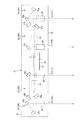
スキャナユニット12は、本体ケーシング2内の上部において、後述する複数のプロセス部13の上方にわたって配置されている。図2は、スキャナユニット12の要部構成を側方から見た側面図であり、図6は、スキャナユニット12を側方から見た側断面図である。このスキャナユニット12は、図2および図6に示すように、スキャナケーシング16と、そのスキャナケーシング16内に設けられる光偏向手段としてのポリゴンミラー17、ポリゴンミラー17にレーザ光を照射するためのレーザ照射光学部18、ポリゴンミラー17によって偏向および走査されたレーザ光を像面において等速度の光束に変換するfθレンズ19、fθレンズ19を通過したレーザ光を各色に対応するレーザ光として出射させるための光路形成手段としてのレーザ出射光学部20とを備えている。
The
(Configuration of image forming unit)
The
(Configuration of scanner unit)
The
スキャナケーシング16は、図6に示すように、ボックス形状をなし、その底壁43には、各色に対応する出射窓21が形成されている。各出射窓21は、前後方向の異なる位置に互いに間隔を隔てて設けられており、前方から後方に向かって、各色に対応して、順次、イエロー出射窓21Y、マゼンタ出射窓21M、シアン出射窓21C、ブラック出射窓21Kとして形成されている。
As shown in FIG. 6, the
ポリゴンミラー17は、スキャナケーシング16内の前後方向中央部において、モータ基板22上に、後述する4個のレーザ発光部24に対して、1つ設けられている。
図3は、スキャナユニット12の要部構成を上方から見た平面図である。このポリゴンミラー17は、図3に示すように、複数の反射面を有する多面体(たとえば、6面体)に形成されており、その中心に設けられる回転軸23を中心として、モータ基板22内に収容されているスキャナモータの動力によって、高速で回転駆動される。
One
FIG. 3 is a plan view of the main configuration of the
なお、モータ基板22は、スキャナケーシング16の底壁43に、図示しないボスなどを介して固定されている。
レーザ照射光学部18は、ポリゴンミラー17に対して対称にそれぞれ設けられている。各レーザ照射光学部18は、レーザ発光部24と、コリメートレンズ25と、迷光防止手段としての第1スリット板26と、光路合成手段としての反射ミラー27と、スリット部材としての第2スリット板28と、シリンドリカルレンズ29とを、1組として備えている。
The
The laser irradiation
レーザ発光部24は、半導体レーザなどからなり、各レーザ照射光学部18において、2個1組で設けられている。各レーザ発光部24は、各レーザ発光部24から発光されるレーザ光の光路が互いに直交するように配置されている。また、各レーザ発光部24は、図2に示すように、副走査方向Y(図4参照)において、互いに間隔を隔てて配置されている。
The
図4は、スキャナユニット12のレーザ照射光学部18を、斜め前方から見た斜視図である。コリメートレンズ25は、図4に示すように、各レーザ発光部24に対応してそれぞれ(2個)設けられている。各コリメートレンズ25は、各レーザ発光部24から発光されるレーザ光の通過方向(以下、単にレーザ光の通過方向とする。)において、各レーザ発光部24の下流側に設けられ、各レーザ発光部24とそれぞれ対向配置されている。
FIG. 4 is a perspective view of the laser irradiation
各レーザ発光部24から発光されるレーザ光は、各コリメートレンズ25によって、平行光束となるように変換される。
第1スリット板26は、図3に示すように、2枚の平板が略直角方向に連続する略L字形状のプレートからなり、各平板には、図4に示すように、迷光を防止するための第1スリット30がそれぞれ開口されている。各スリット30は、主走査方向Xに延びる長孔形状に形成されており、副走査方向Yにおいて、各レーザ発光部24に対応する間隔で、互いに間隔を隔てて配置されている。そして、この第1スリット板26は、各第1スリット30が、レーザ光の通過方向において、各コリメートレンズ25の下流側に配置され、各コリメートレンズ25とそれぞれ対向するように配置されている。
Laser light emitted from each laser
As shown in FIG. 3, the
各コリメートレンズ25を通過した各レーザ光は、第1スリット板26の各第1スリット30によって、レーザ光の通過方向に直交する断面形状が制限され、これによって、各レーザ発光部24から発光されるレーザ光の迷光が防止される。
反射ミラー27は、レーザ光の通過方向において、各第1スリット30の下流側に配置されており、略L字形状の第1スリット板26の各平板に対して、略45°に傾斜するように設けられている。この反射ミラー27は、一方のスリット30を通過したレーザ光が、上側において、そのまま直線的に通過し、他方のスリット30を通過したレーザ光が、下側において、略90°反射して略直角に屈折するように形成されている。これによって、2個のレーザ発光部24から互いに直交する方向に発光された2つのレーザ光の光路が、主走査方向Xにおいて一致するように、合成される。
Each laser beam that has passed through each
The
第2スリット板28は、レーザ光の通過方向において、反射ミラー27の下流側に配置されている。この第2スリット板28は、略矩形状の平板からなり、絞り孔としての第2スリット31が、各レーザ発光部24に対応して、それぞれ開口されている。各第2スリット31は、主走査方向Xに延びる長孔形状に形成されており、副走査方向(図4参照)において、各レーザ発光部24に対応する間隔で、互いに間隔を隔てて並列配置されている。これら第2スリット31は、各レーザ光を絞り込めるように、第1スリット板26に形成されている第1スリット30よりも、その開口面積が小さく形成されている。
The
そして、反射ミラー27によって、主走査方向Xの光路が合成された各レーザ光は、各第2スリット31を通過するときに、副走査方向Yにおいて互いに位置調整される。
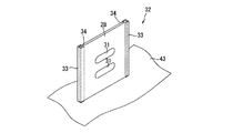
図5は、第2スリット31を前方から見た斜視図である。この第2スリット板28は、図5に示すように、スキャナケーシング16の底壁43から立設するガイド部材32において、固定されている。
Then, the laser beams combined with the optical path in the main scanning direction X by the
FIG. 5 is a perspective view of the
すなわち、ガイド部材32は、第2スリット板28を挟んで対向配置される2つのスライド杆33を備えている。各スライド杆33には、一方が開放される断面コ字形状のスライド溝34が形成されており、各スライド杆33は、互いに第2スリット板28を挟む間隔を隔てて配置され、スライド溝34の開放側が互いに向かい合う状態で、底壁43から立設されている。
That is, the
そして、第2スリット板28は、その幅方向(長手方向および上下方向と直交する方向)両端部を、上方から、各スライド杆33の各スライド溝34に挿入した後、第2スリット板28の下端部が底壁43に当接するまで、各スライド溝34に沿って下方にスライドさせて案内することにより、ガイド部材32に装着されている。第2スリット板28は、ガイド部材32に装着された状態で、各スライド杆33と底壁43とで、位置決めされる。
The
シリンドリカルレンズ29は、レーザ光の通過方向において、第2スリット28の下流側であって、ポリゴンミラー17の上流側に配置されている。このシリンドリカルレンズ29は、副走査方向Yにのみ屈折力を有している。
第2スリット板28の第2スリット28を通過した各レーザ光は、図2に示すように、シリンドリカルレンズ29において、副走査方向Yに収束するように屈折され、その後、ポリゴンミラー17に入射される。
The
As shown in FIG. 2, each laser beam that has passed through the
そして、2つのレーザ照射光学部18は、図3に示すように、ポリゴンミラー17に対して対称となるように、互いに反対側に配置されており、各レーザ照射光学部18のシリンドリカルレンズ29において、副走査方向Yに収束するように屈折された2つのレーザ光は、ポリゴンミラー17に対して、互いに反対側からそれぞれ入射される。これによって、ポリゴンミラー17には、4つのレーザ光が、互いに反対側から、2つを1組として入射される。
As shown in FIG. 3, the two laser irradiation
ポリゴンミラー17では、ポリゴンミラー17の高速回転によって、互いに反対側から入射される2組(4つ)のレーザ光を、それぞれ偏向し、主走査方向Xに走査する。各組における2つのレーザ光は、ポリゴンミラー17の反射面に対してそれぞれ異なる角度で入射するため、反射面からは、次第に副走査方向Y(上下方向)において互いに離間する角度で反射される。
In the
fθレンズ19は、2組のレーザ光に対応するように、各組のレーザ光がポリゴンミラー17に対して入射する方向と直交する方向において、ポリゴンミラー17を挟んで互いに対向するように2つ設けられている。
各fθレンズ19は、各レーザ照射光学部18からポリゴンミラー17に入射し、ポリゴンミラー17によって主走査方向Xに走査される2つのレーザ光を、像面において等速度となる光束に変換する。
Two
Each
レーザ出射光学部20は、図6に示すように、各色に対応して、それぞれ設けられている。すなわち、レーザ出射光学部20は、各色に対応して、イエロー光学部20Y、マゼンタ光学部20M、シアン光学部20Cおよびブラック光学部20Kの4つからなる。
イエロー光学部20Yは、前後方向最前方に配置され、一方のfθレンズ19の上側を通過したレーザ光を反射させる2つの反射鏡35aおよび35bと、反射鏡35aおよび35bで反射されたレーザ光を副走査方向Yに収束させるトロイダルレンズ36とを備えている。
As shown in FIG. 6, the laser emission
The yellow
一方のfθレンズ19の上側を通過したレーザ光は、イエロー光学部20Yにおいて、まず、反射鏡35aにおいて斜め後側上方に反射し、次いで、反射鏡35bにおいて鉛直方向下方に反射した後、トロイダルレンズ36を鉛直方向において通過し、そして、イエロー出射窓21Yから出射される。
マゼンタ光学部20Mは、ポリゴンミラー17とイエロー光学部20Yとの間に配置され、一方のfθレンズ19の下側を通過したレーザ光を反射させる3つの反射鏡37a、37bおよび37cと、反射鏡37a、37bおよび37cで反射されたレーザ光を副走査方向Yに収束させるトロイダルレンズ38とを備えている。
The laser light that has passed through the upper side of one
The magenta
一方のfθレンズ19の下側を通過したレーザ光は、マゼンタ光学部20Mにおいて、まず、反射鏡37aにおいて上方に反射し、次いで、反射鏡37bにおいて後方に反射し、その後、反射鏡37cにおいて鉛直方向下方に反射した後、トロイダルレンズ38を鉛直方向において通過し、そして、マゼンタ出射窓21Mから出射される。
シアン光学部20Cは、ポリゴンミラー17とブラック光学部20Kとの間に配置され、他方のfθレンズ19の下側を通過したレーザ光を反射させる3つの反射鏡39a、39bおよび39cと、反射鏡39a、39bおよび39cで反射されたレーザ光を副走査方向Yに収束させるトロイダルレンズ40とを備えている。
The laser light that has passed under one of the
The cyan
他方のfθレンズ19の下側を通過したレーザ光は、シアン光学部20Cにおいて、まず、反射鏡39aにおいて上方に反射し、次いで、反射鏡39bにおいて前方に反射し、その後、反射鏡39cにおいて鉛直方向下方に反射した後、トロイダルレンズ40を鉛直方向において通過し、そして、シアン出射窓21Cから出射される。
ブラック光学部20Kは、前後方向最後方に配置され、他方のfθレンズ19の上側を通過したレーザ光を反射させる2つの反射鏡41aおよび41bと、反射鏡41aおよび41bで反射されたレーザ光を副走査方向Yに収束させるトロイダルレンズ42とを備えている。
The laser light that has passed through the lower side of the
The black
他方のfθレンズ19の上側を通過したレーザ光は、ブラック光学部20Kにおいて、まず、反射鏡41aにおいて斜め前側上方に反射し、次いで、反射鏡41bにおいて鉛直方向下方に反射した後、トロイダルレンズ42を鉛直方向において通過し、そして、ブラック出射窓21Kから出射される。
なお、マゼンタ光学部20Mとシアン光学部20Cとは、ポリゴンミラー17に対して対称に配置されており、イエロー光学部20Yとブラック光学部20Kとは、マゼンタ光学部20Mとシアン光学部20Cの外側において、ポリゴンミラー17に対して対称に配置されている。
(プロセス部の構成)
プロセス部13は、図1に示すように、複数色のトナーに対応して複数設けられている。すなわち、プロセス部13は、イエロープロセス部13Y、マゼンタプロセス部13M、シアンプロセス部13Cおよびブラックプロセス部13Kの4つからなる。これらプロセス部13は、前方から後方に向かって互いに間隔を隔てて、水平方向において重なるように、順次、並列配置されている。
The laser beam that has passed through the upper side of the
The magenta
(Configuration of process part)
As shown in FIG. 1, a plurality of
各プロセス部13は、感光体としての感光ドラム51、スコロトロン型帯電器52および現像カートリッジ53を備えている。
感光ドラム51は、円筒形状をなし、最表層がポリカーボネートなどからなる正帯電性の感光層により形成されるドラム本体と、このドラム本体の軸心において、ドラム本体の軸方向に沿って延びるドラム軸とを備えている。ドラム本体は、ドラム軸に対して回転自在に設けられ、ドラム軸は、プロセス部13の幅方向(前後方向および上下方向に直交する方向、以下同じ。)両側壁に回転不能に支持されている。そして、感光ドラム51は、画像形成時において、後述する搬送ベルト61との接触位置における搬送ベルト61の移動方向と同方向(図中時計回り)に回転駆動される。
Each
The
スコロトロン型帯電器52は、ワイヤおよびグリッドを備え、帯電バイアスの印加により、コロナ放電を発生させる正帯電型のスコロトロン型帯電器であり、感光ドラム51の後方において、感光ドラム51と接触しないように間隔を隔てて対向配置されている。
現像カートリッジ53は、その筐体内に、現像剤供給手段としての現像ローラ56、供給ローラ57および層厚規制ブレード58を備えている。
The
The developing
現像ローラ56は、感光ドラム51の前方において感光ドラム51と対向配置されている。この現像ローラ56は、金属製のローラ軸に、導電性のゴム材料などの弾性部材からなるローラ部分が被覆されている。より具体的には、ローラ部分は、カーボン微粒子などを含む導電性のウレタンゴム、シリコーンゴムまたはEPDMゴムなどからなる弾性体のローラ層と、そのローラ層の表面に被覆され、ウレタンゴム、ウレタン樹脂、ポリイミド樹脂などが主成分とされるコート層との2層構造によって形成されている。また、現像ローラ56のローラ軸は、現像カートリッジ53の筐体の幅方向両側壁に回転自在に支持されており、画像形成時には、現像バイアスが印加される。
The developing
供給ローラ57は、現像ローラ56の前方において現像ローラ56と対向配置され、現像ローラ56と圧接されている。この供給ローラ57は、金属製のローラ軸に、導電性のスポンジ部材からなるローラ部分が被覆されている。また、供給ローラ57のローラ軸は、現像カートリッジ53の筐体の幅方向両側壁に回転自在に支持されている。
層厚規制ブレード58は、金属の板ばね材からなり、その先端部に、絶縁性のシリコーンゴムからなる断面半円形状の押圧部材を備えている。そして、層厚規制ブレード58は、現像ローラ56の上方において現像カートリッジ53の筐体に支持され、その先端部(下端部)の押圧部材が、現像ローラ56に対して前側上方から圧接されている。
The
The layer
また、現像カートリッジ53の筐体の上側部分は、トナーを収容するトナー収容室55として形成されており、各色のトナーが収容されている。すなわち、イエロープロセス部13Yのトナー収容室55内には、イエローの色を有する正帯電性の非磁性1成分の重合トナーが収容されている。マゼンタプロセス部13Mのトナー収容室55内には、マゼンタの色を有する正帯電性の非磁性1成分の重合トナーが収容されている。シアンプロセス部13Cのトナー収容室55内には、シアンの色を有する正帯電性の非磁性1成分の重合トナーが収容されている。ブラックプロセス部13Kのトナー収容室55内には、ブラックの色を有する正帯電性の非磁性1成分の重合トナーが収容されている。
The upper portion of the housing of the developing
より具体的には、各色のトナーは、重合法により得られた略球形の重合トナーが用いられている。重合トナーは、スチレンなどのスチレン系単量体や、アクリル酸、アルキル(C1〜C4)アクリレート、アルキル(C1〜C4)メタアクリレートなどのアクリル系単量体を、懸濁重合などの公知の重合方法によって共重合させることにより得られる結着樹脂を主成分とし、これに、着色剤、荷電制御剤、ワックスなどが配合されることによりトナー母粒子が形成され、さらにこれに、流動性の向上を図るべく外添剤が添加されてなるものである。 More specifically, for each color toner, a substantially spherical polymer toner obtained by a polymerization method is used. The polymerization toner is a known polymerization such as a suspension polymerization of a styrene monomer such as styrene or an acrylic monomer such as acrylic acid, alkyl (C1 to C4) acrylate, or alkyl (C1 to C4) methacrylate. The main component is a binder resin obtained by copolymerization according to the method, and a toner base particle is formed by adding a colorant, a charge control agent, a wax, etc. to this, and further improves the fluidity. In order to achieve this, an external additive is added.
着色剤としては、上記した、イエロー、マゼンタ、シアンおよびブラックの各着色剤が配合されている。また、荷電制御剤としては、たとえば、アンモニウム塩などのイオン性官能基を有するイオン性単量体と、スチレン系単量体やアクリル系単量体などのイオン性単量体と共重合可能な単量体との共重合によって得られる荷電制御樹脂が配合されている。また、外添剤としては、たとえば、シリカ、酸化アルミニウム、酸化チタン、チタン酸ストロンチウム、酸化セリウム、酸化マグネシウムなどの金属酸化物の粉末や、炭化物の粉末、金属塩の粉末などの無機粉末が配合されている。 As the colorant, the above-mentioned yellow, magenta, cyan and black colorants are blended. Moreover, as a charge control agent, for example, an ionic monomer having an ionic functional group such as an ammonium salt and an ionic monomer such as a styrene monomer or an acrylic monomer can be copolymerized. A charge control resin obtained by copolymerization with a monomer is blended. As external additives, for example, powders of metal oxides such as silica, aluminum oxide, titanium oxide, strontium titanate, cerium oxide and magnesium oxide, inorganic powders such as carbide powders and metal salt powders are blended. Has been.
そして、各プロセス部13では、画像形成時には、各トナー収容室55に収容されている各色のトナーが、供給ローラ57に供給され、この供給ローラ57の回転により現像ローラ56に供給される。このとき、トナーは、供給ローラ57と、現像バイアスが印加されている現像ローラ56との間で正に摩擦帯電される。現像ローラ56上に供給されたトナーは、現像ローラ56の回転に伴って、層厚規制ブレード58と現像ローラ56との間に進入し、一定厚さの薄層となって、現像ローラ56上に担持される。
In each
一方、スコロトロン型帯電器52は、帯電バイアスの印加により、コロナ放電を発生させて、感光ドラム51の表面を一様に正帯電させている。感光ドラム51の表面は、感光ドラム51の回転に伴なって、スコロトロン型帯電器52により一様に正帯電された後、スキャナユニット12の出射窓21から出射されたレーザ光の高速走査により露光され、用紙3に形成すべき画像に対応した各色の静電潜像が形成される。
On the other hand, the
さらに感光ドラム51が回転すると、次いで、現像ローラ56の表面に担持されかつ正帯電されているトナーが、現像ローラ56の回転により、感光ドラム51に対向して接触するときに、感光ドラム51の表面に形成されている静電潜像、すなわち、一様に正帯電されている感光ドラム51の表面のうち、レーザ光によって露光され電位が下がっている露光部分に供給される。これにより、感光ドラム51の静電潜像は、可視像化され、感光ドラム51の表面には、各色に対応して、反転現像によるトナー像が担持される。
(転写部の構成)
転写部14は、本体ケーシング2内において、用紙カセット7の上方であって、プロセス部13の下方において、前後方向に沿って配置されている。この転写部14は、駆動ローラ59、従動ローラ60、搬送ベルト61、転写ローラ62およびベルトクリーニング部63を備えている。
When the
(Configuration of transfer section)
The
駆動ローラ59は、ブラックプロセス部13Kの感光ドラム51よりも後方下側に配置されている。この駆動ローラ59は、画像形成時において、感光ドラム51の回転方向と逆方向(図中反時計回り)に回転駆動される。
従動ローラ60は、イエロープロセス部13Yの感光ドラム51よりも前方下側であって、駆動ローラ59と前後方向において対向するように配置されている。この従動ローラ60は、駆動ローラ59の回転駆動時に、駆動ローラ59の回転方向と同方向(図中反時計回り)に従動回転する。
The
The driven
搬送ベルト61は、エンドレスベルトからなり、カーボンなどの導電性粒子を分散した導電性のポリカーボネートやポリイミドなどの樹脂によって形成されている。この搬送ベルト61は、駆動ローラ59と従動ローラ60との間に巻回されており、その巻回されている外側の接触面が、各プロセス部13の感光ドラム51のすべてと対向接触するように、配置されている。
The
そして、駆動ローラ59の駆動により、従動ローラ60が従動され、搬送ベルト61が、これら駆動ローラ59および従動ローラ60の間を、各プロセス部13の感光ドラム51と対向接触する接触面において、感光ドラム51と同方向に回転するように、矢印Aで示す方向(図中反時計回り)に周回移動される。
転写ローラ62は、駆動ローラ59および従動ローラ60の間に巻回されている搬送ベルト61内において、各プロセス部13の感光ドラム51と搬送ベルト61を挟んで対向配置されている。各転写ローラ62は、金属製のローラ軸に、導電性のゴム材料などの弾性部材からなるローラ部分が被覆されている。そして、転写ローラ62のローラ軸は、幅方向に沿って延び、回転自在に支持されており、転写時には転写バイアスが印加される。各転写ローラ62は、搬送ベルト61と対向接触する接触面において、搬送ベルト61の周回移動方向と同方向(図中反時計回り)に回転する。
The driven
The
そして、給紙部4から給紙された用紙3は、駆動ローラ59の駆動および従動ローラ60の従動により周回移動される搬送ベルト61によって、前方から後方に向かって、搬送ベルト61と各プロセス部13の感光ドラム51との間の画像形成位置を、順次通過するように搬送される。そして、その搬送中に、各プロセス部13の感光ドラム51に担持されている各色に対応したトナー像が順次転写され、これによって、用紙3にカラー画像が形成される。
Then, the
すなわち、たとえば、イエロープロセス部13Yの感光ドラム51の表面に担持されたイエローのトナー像が、用紙3に転写されると、次いで、マゼンタプロセス部13Mの感光ドラム51の表面に担持されたマゼンタのトナー像が、既にイエローのトナー像が転写されている用紙3に重ねて転写され、同様の動作によって、シアンプロセス部13Cの感光ドラム51の表面に担持されたシアンのトナー像、ブラックプロセス部13Kの感光ドラム51の表面に担持されたブラックのトナー像が重ねて転写され、これによって、用紙3にカラー画像が形成される。
That is, for example, when a yellow toner image carried on the surface of the
このようなカラー画像の形成において、このカラーレーザプリンタ1は、各プロセス部13において、プロセス部13が各色に対応して複数設けられているタンデム型の装置構成であるため、モノクロ画像を形成する速度とほぼ同じ速度で、各色に対応したトナー像を形成して、迅速なカラー画像の形成を達成することができる。そのため、小型化を図りつつ、カラー画像を形成することができる。
In forming such a color image, the color laser printer 1 forms a monochrome image because each
ベルトクリーニング部63は、搬送ベルト61の下方であって、ブラックプロセス部13Kと搬送ベルト61を挟んで対向配置されている。
このベルトクリーニング部63は、搬送ベルト61の表面に接触するように配置され、その搬送ベルト61の表面に付着した紙粉やトナーなどを掻き取るための1次クリーニングローラ64と、その1次クリーニングローラ64と接触するように配置され、1次クリーニングローラ64によって掻き取られた紙粉やトナーなどを電気的に回収する2次クリーニングローラ65と、2次クリーニングローラ65に接触し、2次クリーニングローラ65に回収された紙粉やトナーなどを掻き取る掻取ブレード66と、掻取ブレード66によって掻き取られた紙粉やトナーなどを貯留するクリーニングボックス67とを備えている。
The
The
このベルトクリーニング部63では、搬送ベルト61の表面に付着した紙粉やトナーなどが、まず、1次クリーニングローラ64によって掻き取られた後、1次クリーニングローラ64によって掻き取られた紙粉やトナーなどが、2次クリーニングローラ65によって電気的に回収される。その後、2次クリーニングローラ65に回収された紙粉やトナーなどが、掻取ブレード66によって掻き取られた後、クリーニングボックス67内に貯留される。
(定着部の構成)
定着部15は、転写部14の後方に配置されている。この定着部15は、加熱ローラ68、加圧ローラ69および搬送ローラ70を備えている。加熱ローラ68は、その表面に離型層が形成される金属素管からなり、その軸方向に沿ってハロゲンランプが内装されている。そして、ハロゲンランプにより、加熱ローラ68の表面が定着温度に加熱される。また、加圧ローラ69は、加熱ローラ68を押圧するように設けられている。また、搬送ローラ70は、上下1対のローラからなり、加熱ローラ68および加圧ローラ69の後方に配置されている。
In the
(Configuration of fixing unit)
The fixing
そして、用紙3上に転写されたカラー画像は、次いで、定着部15に搬送され、用紙3が加熱ローラ68と加圧ローラ69との間を通過する間に、加熱および加圧されることによって用紙3に熱定着される。熱定着された用紙3は、搬送ローラ70によって排紙部6に送られる。
(排紙部の構成)
排紙部6は、排紙パス71、排紙ローラ72および排紙トレイ73を備えている。
The color image transferred onto the
(Configuration of paper output unit)
The paper discharge unit 6 includes a
排紙パス71は、上流側端部が、下方において搬送ローラ70に隣接し、用紙3が後方に向かって給紙されるように、また、下流側端部が、上方において排紙ローラ72に隣接し、用紙3が前方に向かって排紙されるような、略U字形状の用紙3の搬送経路として形成されている。排紙ローラ72は、排紙パス71の下流側端部に、1対のローラとして設けられている。排紙トレイ73は、本体ケーシング2の上面に、前方から後方に向かって下方に傾斜する傾斜壁として形成されている。
The
そして、搬送ローラ70から送られた用紙3は、排紙パス71内において、搬送方向が前後反転された後、排紙ローラ72によって、前方に向かって排紙される。排紙された用紙3は、排紙トレイ73上に載置される。
(スキャナユニットの説明)
このようなカラーレーザプリンタ1において、スキャナユニット12では、ポリゴンミラー17を挟んで対向配置される2つのレーザ照射光学部18において、互いに直交配置され、副走査方向Yにおいて互いに間隔を隔てて配置されている2個のレーザ発光部24から発光された2つのレーザ光は、それぞれ、2つのコリメートレンズ25によって、平行光束となるように変換された後、第1スリット板26の2つの第1スリット30をそれぞれ通過して、それぞれの迷光が防止される。
The
(Description of the scanner unit)
In such a color laser printer 1, in the
その後、2つのレーザ光は、反射ミラー27において、一方のレーザ光が直線的に通過する一方、他方のレーザ光が略90°反射して略直角に屈折し、2つのレーザ光の光路が、副走査方向Yにおいて間隔を隔てた状態で、主走査方向Xにおいて一致するように合成される。
そして、光路が合成された2つのレーザ光は、第2スリット板28の副走査方向Yにおいて並列配置されている2つの第2スリット31をそれぞれ通過し、このとき、2つのレーザ光は、副走査方向Yにおいて互いに位置調整される。これによって、反射ミラー27によって主走査方向Xが一致する2つのレーザ光は、たとえ、反射ミラー27の加工精度あるいはコリメート光学系の位置精度に起因して、副走査方向Yにおいて誤差を生じても、その誤差が調整される。
Thereafter, the two laser beams are linearly transmitted through the
Then, the two laser beams combined in the optical path pass through the two
その後、2つの第2スリット31をそれぞれ通過した2つのレーザ光は、1つのシリンドリカルレンズ29において、副走査方向Yにおいて収束するように屈折され、その後、ポリゴンミラー17に、異なる角度でそれぞれ入射される。
ポリゴンミラー17に入射される2つのレーザ光は、上記したように、主走査方向Xのみならず、第2スリット板28の2つの第2スリット31によって、副走査方向Yにおいても誤差が低減されているので、ポリゴンミラー17において、2つのレーザ照射光学部18から入射される4つのレーザ光を精度よく偏向および走査することができる。
Thereafter, the two laser beams respectively passing through the two
As described above, the errors of the two laser beams incident on the
しかも、各レーザ照射光学部18では、各レーザ光を通過させる各第2スリット31が、同一の第2スリット板28に設けられているので、各レーザ光の間の相対位置精度が高く、ポリゴンミラー17に入射する各レーザ光の精度のよい相対位置を確保することができる。そのため、ポリゴンミラー17において、各レーザ光相互間の精度のよい偏向および走査を確保することができる。
In addition, in each laser irradiation
さらに、第2スリット板28は、ガイド部材32の2つのスライド杆33において、スライド自在に案内されて、各スライド杆33と底壁43とで位置決めされている。そのため、第2スリット板28を精度のよく位置決めして、その第2スリット板28に配置されている各第2スリット31を、精度よく配置することができる。そのため、より一層、各レーザ光の精度のよい偏向および走査を達成することができる。
Further, the
また、このスキャナユニット12では、各レーザ照射光学部18において、2つのレーザ発光部24と反射ミラー27との間には、2つの第1スリット30が2つのコリメートレンズ25に対向するように、第1スリット板26が設けられている。そして、この第1スリット板26の2つの第1スリット30では、2つのレーザ光の断面形状をそれぞれ制限する。そのため、一方のレーザ発光部24から発光されたレーザ光が、他方のレーザ発光部24から発光されたレーザ光に対して干渉することを確実に防止することができる。その結果、第1スリット板26の2つの第1スリット30によって、2つのレーザ発光部24から発光されるレーザ光の迷光をそれぞれ防止することができる。
In the
また、各レーザ照射光学部18では、レーザ発光部24は、2個1組として配置されており、第2スリット板28は、2個1組に対して1つ設けられており、第2スリット31は、2個1組のレーザ発光部24に対応して、それぞれ形成されている。これによって、4個のレーザ発光部24を2組に分けて、2つのレーザ照射光学部18に配置することにより、効率のよいレイアウトを確保しつつ、各レーザ光の精度のよい偏向および走査を達成することができる。
Moreover, in each laser irradiation
また、このスキャナユニット12では、2つのレーザ照射光学部18は、ポリゴンミラー17に対して対称となるように、互いに反対側に配置されている。つまり、各レーザ照射光学部18において、2個1組として設けられているレーザ発光部24は、ポリゴンミラー17に対して対称となるように、互いに反対側に配置されている。また、fθレンズ19は、2つのレーザ照射光学部18、つまり、2個1組のレーザ発光部24からそれぞれ発光される2組のレーザ光に対応するように、2組のレーザ光がポリゴンミラー17に対して入射する方向と直交する方向において、ポリゴンミラー17を挟んで互いに対向するように2つ設けられている。そして、2つのfθレンズ19をそれぞれ通過した2つ1組のレーザ光、つまり4つのレーザ光は、その後、それぞれ独立した光路である、イエロー光学部20Y、マゼンタ光学部20M、シアン光学部20Cおよびブラック光学部20Kを通過して、イエロー出射窓21Y、マゼンタ出射窓21M、シアン出射窓21Cおよびブラック出射窓21Kからそれぞれ出射される。
In the
これによって、ポリゴンミラー17に対して2個1組として対称に配置された2組のレーザ発光部24から発光された2組4つのレーザ光は、対称方向からポリゴンミラー17に照射され、偏向および主走査方向Xに走査された後、2つのfθレンズ19をそれぞれ通過して、像面において等速度となる光束に変換される。そして、2組4つのレーザ光は、各レーザ出射光学部20によって、それぞれ異なる出射窓21から出射される。そのため、スキャナユニット12をコンパクトに構成することができながら、精度よく偏向および走査された4つのレーザ光を、それぞれ異なる出射窓21から出射させることができる。
As a result, two sets of four laser beams emitted from two sets of laser
そして、このカラーレーザプリンタ1では、上記したスキャナユニット12の4つの出射窓21から出射したレーザ光に対応して、4つのプロセス部13が設けられており、各プロセス部13に設けられる4つの感光ドラム51には、それぞれ独立した各レーザ光が照射されることにより、静電潜像が形成される。
そして、4つの感光ドラム51に形成された4つの静電潜像は、各プロセス部13に設けられた4つの現像ローラ56によって、それぞれ、イエロー、マゼンタ、シアンおよびブラックの色に対応する現像剤で現像された後、転写部14において、同一の用紙3に、順次色重ねされる。
In this color laser printer 1, four
The four electrostatic latent images formed on the four
そのため、このレーザプリンタ1では、精度のよい静電潜像を、各感光ドラム51に形成して、精度のよいカラー画像の形成を達成することができながら、モノクロ画像とほぼ同じ速度でカラー画像を形成することができる。
なお、上記の説明において、第2スリット板28に形成される2つの第2スリット31は、開口形状および開口面積において、ともに同一であってもよく、また、それぞれ、レーザ発光部24の種類や現像される色に対応して、適宜変更することもできる。
For this reason, in this laser printer 1, an accurate electrostatic latent image can be formed on each
In the above description, the two
また、2つの第2スリット31の副走査方向Yにおける間隔も、レーザ発光部24の種類や現像される色に対応して、適宜決定される。
また、上記の説明では、2個1組のレーザ発光部24を備えるレーザ照射光学部18を、ポリゴンミラー17に対して対称に2つ配置したが、各レーザ発光部24の配置などは特に制限されず、たとえば、4個1組のレーザ発光部24を備える1つのレーザ照射光学部18を、ポリゴンミラー17に対して一方側に配置することもできる。
Further, the interval between the two
Further, in the above description, two laser irradiation
このような配置においては、第2スリット板28には、4つの第2スリット31が、副走査方向Yにおいて、互いに間隔を隔てて並列して開口される。
In such an arrangement, four
1 カラーレーザプリンタ
15 感光ドラム
17 ポリゴンミラー
19 fθレンズ
20 レーザ出射光学部
24 レーザ発光部
26 第1スリット板
27 反射ミラー
28 第2スリット板
31 第2スリット
32 ガイド部材
51 感光ドラム
56 現像ローラ
DESCRIPTION OF SYMBOLS 1
Claims (9)
複数の前記レーザ発光部から発光されたレーザ光を主走査方向に偏向および走査する光偏向手段と、
レーザ光の通過方向において、複数の前記レーザ発光部と前記光偏向手段との間に配置され、複数の前記レーザ発光部から発光された複数のレーザ光を、主走査方向において一致させる光路合成手段と、
レーザ光の通過方向において、前記光路合成手段と前記光偏向手段との間に配置され、複数の前記レーザ発光部から発光された複数のレーザ光に対応して形成される絞り孔が、副走査方向に並んで配置されているスリット部材とを備えていることを特徴とする、スキャナ装置。 A plurality of laser light emitting sections for emitting laser light;
A light deflecting means for deflecting and scanning the laser light emitted from the plurality of laser light emitting sections in the main scanning direction;
An optical path synthesizing unit that is arranged between the plurality of laser light emitting units and the light deflecting unit in the laser beam passing direction and matches the plurality of laser beams emitted from the plurality of laser light emitting units in the main scanning direction. When,
An aperture hole disposed between the optical path combining unit and the optical deflecting unit in the laser beam passing direction and formed corresponding to the plurality of laser beams emitted from the plurality of laser emission units is sub-scanning. A scanner device comprising: a slit member arranged side by side in a direction.
前記スリット部材は、各組に対して1つ設けられており、
前記絞り孔は、各組の前記レーザ発光部に対応して、それぞれ形成されていることを特徴とする、請求項1ないし4のいずれかに記載のスキャナ装置。 The laser emission unit is arranged as a plurality of sets,
One slit member is provided for each group,
The scanner device according to any one of claims 1 to 4, wherein the aperture holes are respectively formed corresponding to the laser light emitting units of each set.
各組の前記レーザ発光部から発光され、前記光偏向手段により偏向および走査された各組のレーザ光に対応して2つ設けられ、各組のレーザ光を、像面において等速度となる光束に変換するfθレンズと、
各前記fθレンズを通過した各レーザ光を、異なる位置からそれぞれ出射させるための光路形成手段とを備えていることを特徴とする、請求項1ないし5のいずれかに記載のスキャナ装置。 The plurality of laser light emitting units are arranged symmetrically as a set of two with respect to the light deflection means,
Two light beams are provided corresponding to each set of laser beams that are emitted from each set of the laser light emitting units and deflected and scanned by the light deflecting unit, and each set of laser beams has a constant velocity on the image plane. An fθ lens that converts to
6. The scanner device according to claim 1, further comprising: optical path forming means for emitting each laser beam that has passed through each fθ lens from a different position.
前記光偏向手段によって主走査方向に偏向および走査された複数のレーザ光がそれぞれ照射され、その照射により静電潜像がそれぞれ形成される複数の感光体とを備えていること特徴とする、画像形成装置。 A scanner device according to any one of claims 1 to 6;
An image comprising: a plurality of photoconductors each irradiated with a plurality of laser beams deflected and scanned in the main scanning direction by the light deflecting unit, and forming an electrostatic latent image by the irradiation. Forming equipment.
複数の前記レーザ発光部から発光されたレーザ光を主走査方向に偏向および走査する光偏向手段と、
レーザ光の通過方向において、複数の前記レーザ発光部と前記光偏向手段との間に配置され、複数の前記レーザ発光部から発光された複数のレーザ光を、主走査方向において一致させる光路合成手段と、
レーザ光の通過方向において、前記光路合成手段と前記光偏向手段との間に配置され、複数の前記レーザ発光部から発光された複数のレーザ光に対応して形成される絞り孔が、副走査方向に並んで配置されているスリット部材と、
前記光偏向手段によって主走査方向に偏向および走査された複数のレーザ光がそれぞれ照射され、その照射により静電潜像がそれぞれ形成される複数の感光体とを備えていること特徴とする、画像形成装置。 A plurality of laser light emitting sections for emitting laser light;
A light deflecting means for deflecting and scanning the laser light emitted from the plurality of laser light emitting sections in the main scanning direction;
An optical path synthesizing unit that is arranged between the plurality of laser light emitting units and the light deflecting unit in the laser beam passing direction and matches the plurality of laser beams emitted from the plurality of laser light emitting units in the main scanning direction. When,
An aperture hole disposed between the optical path combining unit and the optical deflecting unit in the laser beam passing direction and formed corresponding to the plurality of laser beams emitted from the plurality of laser emission units is sub-scanning. A slit member arranged side by side in the direction;
An image comprising: a plurality of photoconductors each irradiated with a plurality of laser beams deflected and scanned in the main scanning direction by the light deflecting unit, and forming an electrostatic latent image by the irradiation. Forming equipment.
各前記感光体に対応して4つ設けられ、互いに異なる色の現像剤を各前記感光体に供給する現像剤供給手段を備えていることを特徴とする、請求項7または8に記載の画像形成装置。 Four photoreceptors are provided,
9. The image according to claim 7, further comprising developer supply means that is provided corresponding to each of the photoconductors and supplies developer of different colors to the photoconductors. Forming equipment.
Priority Applications (2)
| Application Number | Priority Date | Filing Date | Title |
|---|---|---|---|
| JP2004374373A JP2006178372A (en) | 2004-12-24 | 2004-12-24 | Scanner and image forming apparatus |
| US11/311,471 US20060139715A1 (en) | 2004-12-24 | 2005-12-20 | Optical scanning device and image forming apparatus |
Applications Claiming Priority (1)
| Application Number | Priority Date | Filing Date | Title |
|---|---|---|---|
| JP2004374373A JP2006178372A (en) | 2004-12-24 | 2004-12-24 | Scanner and image forming apparatus |
Publications (1)
| Publication Number | Publication Date |
|---|---|
| JP2006178372A true JP2006178372A (en) | 2006-07-06 |
Family
ID=36732521
Family Applications (1)
| Application Number | Title | Priority Date | Filing Date |
|---|---|---|---|
| JP2004374373A Pending JP2006178372A (en) | 2004-12-24 | 2004-12-24 | Scanner and image forming apparatus |
Country Status (1)
| Country | Link |
|---|---|
| JP (1) | JP2006178372A (en) |
Cited By (6)
| Publication number | Priority date | Publication date | Assignee | Title |
|---|---|---|---|---|
| EP1892946A1 (en) | 2006-08-21 | 2008-02-27 | Brother Kogyo Kabushiki Kaisha | Optical scanner used in color image-forming device |
| JP2009103816A (en) * | 2007-10-22 | 2009-05-14 | Canon Inc | Optical scanner |
| JP2009300982A (en) * | 2008-06-17 | 2009-12-24 | Konica Minolta Business Technologies Inc | Tandem type scanning optical system |
| JP2010032682A (en) * | 2008-07-28 | 2010-02-12 | Ricoh Co Ltd | Optical scanner and image forming apparatus |
| US8634123B2 (en) | 2007-09-14 | 2014-01-21 | Brother Kogyo Kabushiki Kaisha | Optical scanning device and image forming apparatus |
| JP2015022158A (en) * | 2013-07-19 | 2015-02-02 | 株式会社リコー | Optical scanner and image display device |
-
2004
- 2004-12-24 JP JP2004374373A patent/JP2006178372A/en active Pending
Cited By (8)
| Publication number | Priority date | Publication date | Assignee | Title |
|---|---|---|---|---|
| EP1892946A1 (en) | 2006-08-21 | 2008-02-27 | Brother Kogyo Kabushiki Kaisha | Optical scanner used in color image-forming device |
| US7961210B2 (en) | 2006-08-21 | 2011-06-14 | Brother Kogyo Kabushiki Kaisha | Optical scanner used in color image-forming device |
| US8462189B2 (en) | 2006-08-21 | 2013-06-11 | Brother Kogyo Kabushiki Kaisha | Optical scanner used in color image-forming device |
| US8634123B2 (en) | 2007-09-14 | 2014-01-21 | Brother Kogyo Kabushiki Kaisha | Optical scanning device and image forming apparatus |
| JP2009103816A (en) * | 2007-10-22 | 2009-05-14 | Canon Inc | Optical scanner |
| JP2009300982A (en) * | 2008-06-17 | 2009-12-24 | Konica Minolta Business Technologies Inc | Tandem type scanning optical system |
| JP2010032682A (en) * | 2008-07-28 | 2010-02-12 | Ricoh Co Ltd | Optical scanner and image forming apparatus |
| JP2015022158A (en) * | 2013-07-19 | 2015-02-02 | 株式会社リコー | Optical scanner and image display device |
Similar Documents
| Publication | Publication Date | Title |
|---|---|---|
| US20060139715A1 (en) | Optical scanning device and image forming apparatus | |
| US7099061B2 (en) | Image-forming device and scanning unit for use therein | |
| JP4337053B2 (en) | Optical scanning apparatus and image forming apparatus | |
| US9367027B2 (en) | Photosensitive cartridge having light guide | |
| US7245409B2 (en) | Scanner apparatus and image forming apparatus | |
| US7782353B2 (en) | Image-forming device | |
| US7400843B2 (en) | Color image forming apparatus | |
| US7342699B2 (en) | Scanner apparatus and image forming apparatus including a lens having a thin portion formed to extend in one scanning direction | |
| JP2006178372A (en) | Scanner and image forming apparatus | |
| US20120050827A1 (en) | Optical scanning device and image forming apparatus | |
| JP4529677B2 (en) | Optical scanning apparatus and image forming apparatus | |
| US8872874B2 (en) | Light scanning unit and electrophotographic image forming apparatus using the same | |
| US7054047B2 (en) | Polygon mirror and optical scanning device having the same | |
| JP5489074B2 (en) | Image forming apparatus | |
| JP6848293B2 (en) | Optical scanning device and image forming device | |
| JP4800897B2 (en) | Optical scanning apparatus and image forming apparatus | |
| JP6358196B2 (en) | Mirror support structure, optical scanning device, image forming apparatus | |
| JP6409649B2 (en) | Optical scanning device and image forming apparatus | |
| JP2020166064A (en) | Method for manufacturing scanning optical device and method for adjusting scanning optical device | |
| JP2010096849A (en) | Optical scanner and image forming apparatus | |
| JP6299946B2 (en) | Image forming method and image forming apparatus | |
| JP6409650B2 (en) | Optical scanning device and image forming apparatus | |
| JP2022036492A (en) | Optical scanner and image forming apparatus | |
| JP2005292460A (en) | Image forming apparatus and process cartridge | |
| JP2005115260A (en) | Image forming apparatus |