JP2006178205A - Digital platform device - Google Patents
Digital platform device Download PDFInfo
- Publication number
- JP2006178205A JP2006178205A JP2004371678A JP2004371678A JP2006178205A JP 2006178205 A JP2006178205 A JP 2006178205A JP 2004371678 A JP2004371678 A JP 2004371678A JP 2004371678 A JP2004371678 A JP 2004371678A JP 2006178205 A JP2006178205 A JP 2006178205A
- Authority
- JP
- Japan
- Prior art keywords
- image data
- image
- receiving
- digital platform
- unit
- Prior art date
- Legal status (The legal status is an assumption and is not a legal conclusion. Google has not performed a legal analysis and makes no representation as to the accuracy of the status listed.)
- Granted
Links
Images


Classifications
-
- G—PHYSICS
- G06—COMPUTING; CALCULATING OR COUNTING
- G06F—ELECTRIC DIGITAL DATA PROCESSING
- G06F3/00—Input arrangements for transferring data to be processed into a form capable of being handled by the computer; Output arrangements for transferring data from processing unit to output unit, e.g. interface arrangements
- G06F3/01—Input arrangements or combined input and output arrangements for interaction between user and computer
- G06F3/03—Arrangements for converting the position or the displacement of a member into a coded form
- G06F3/041—Digitisers, e.g. for touch screens or touch pads, characterised by the transducing means
- G06F3/042—Digitisers, e.g. for touch screens or touch pads, characterised by the transducing means by opto-electronic means
- G06F3/0425—Digitisers, e.g. for touch screens or touch pads, characterised by the transducing means by opto-electronic means using a single imaging device like a video camera for tracking the absolute position of a single or a plurality of objects with respect to an imaged reference surface, e.g. video camera imaging a display or a projection screen, a table or a wall surface, on which a computer generated image is displayed or projected
Abstract
Description
本発明はデジタルプラットフォーム装置に関し、より詳細には、画像データをより扱いやすくするためのユーザインターフェースの改良に関する発明である。 The present invention relates to a digital platform device, and more particularly to an improvement in a user interface for making image data easier to handle.
近年、すでにテーブル型ディスプレイとして、プロジェクタを利用したテーブル状のディスプレイに画像データを表示して、複数の人が楽しめる表示手段を提供するテーブル型ディスプレイ装置が提案されている。 In recent years, as a table type display, a table type display device has been proposed in which image data is displayed on a table-like display using a projector to provide display means that can be enjoyed by a plurality of people.
そして、例えば、プロジェクタから投与された光束をミラーで反射して水平設置型のスクリーンの所定領域に投与するテーブル型ディスプレイであって、上記スクリーンを、撓みを少なくするための透明ベース部材と、像を結像する拡散スクリーンとで構成した装置が知られている(例えば、特許文献1参照)。
ところで、テーブル型ディスプレイでは、そのテーブル上に機器を載置することができるが、上記特許文献1に記載の装置では、その点までは言及されていないものであった。したがって、テーブル上に載置された機器から、該機器に収納されている画像データを近傍に表示して、データを簡単に確認できるといった工夫が必要となる。
By the way, in the table type display, an apparatus can be placed on the table. However, in the apparatus described in
加えて、従来は、データを授受する場合、送信装置と受信装置との間には、単なる信号線や電波や光通信を行うための空間があるだけで、その送受信の関係が不明瞭なため、ユーザにわかりにくいものとなっていた。 In addition, conventionally, when data is exchanged, there is simply a space for signal lines, radio waves, and optical communication between the transmitting device and the receiving device, and the transmission / reception relationship is unclear. It was difficult for the user to understand.
したがって本発明は、テーブル上に載置される機器やデータの存在する場所、送るべき信号や受信すべき信号の送受信信過程を明確にして、ユーザにわかりやすく確実な信号の送受信をすることができるデジタルプラットフォーム装置を提供することを目的とする。 Therefore, the present invention makes it possible to clearly transmit and receive signals clearly and clearly to the user by clarifying the place where devices and data are placed on the table, the signal transmission and reception processes of signals to be transmitted and received. An object of the present invention is to provide a digital platform device that can be used.
すなわち請求項1に記載の発明は、画像データを格納し、格納された画像データを送信可能な送信装置、並びに画像データを受信可能な受信装置をそれぞれ載置する平面部を有するデジタルプラットフォーム装置であって、上記送信装置と上記受信装置の置かれた位置をそれぞれ検出する位置検出手段と、所定の命令操作に応じて、上記送信装置から上記受信装置への画像データ転送を制御する制御手段と、上記画像データの転送に際して、当該転送画像を上記平面部に表示する表示手段と、を具備し、上記制御手段は、上記送信装置に記録された全画像データを上記送信装置の近傍に縮小表示させ、上記所定の操作により指定された画像データを上記受信装置に転送する際に、これら転送される画像データの縮小画像を上記受信装置の近傍に表示させることを特徴とする。
That is, the invention described in
請求項2に記載の発明は、請求項1に記載の発明に於いて、上記平面部は、光拡散性を有する半透明部材であり、平面部下部に配されたプロジェクタ装置により表示を行うものであることを特徴とする。 According to a second aspect of the present invention, in the first aspect of the present invention, the planar portion is a translucent member having light diffusibility, and performs display by a projector device disposed under the planar portion. It is characterized by being.
請求項3に記載の発明は、請求項1に記載の発明に於いて、上記位置検出手段は、上記送信装置並びに上記受信装置とデータ通信を行うためのインタフェース手段を含むことを特徴とする。 According to a third aspect of the present invention, in the first aspect of the present invention, the position detecting means includes interface means for performing data communication with the transmitting apparatus and the receiving apparatus.
請求項4に記載の発明は、画像データを送信する送信手段と、上記画像データを受信する受信手段と、上記画像データを上記送信手段から受信手段に転送制御する制御手段と、を有するデジタルプラットフォーム装置に於いて、上記制御手段は、上記送信手段と受信手段の位置を検出する検出手段と、上記画像データを表示する表示手段とを有することを特徴とする。 According to a fourth aspect of the present invention, there is provided a digital platform comprising: transmission means for transmitting image data; reception means for receiving the image data; and control means for controlling transfer of the image data from the transmission means to the reception means. In the apparatus, the control means includes detection means for detecting positions of the transmission means and the reception means, and display means for displaying the image data.
請求項5に記載の発明は、請求項4に記載の発明に於いて、上記表示手段は、上記送信手段の位置を検出して、その近傍に上記送信手段が送信する画像データを表示することを特徴とする。
The invention according to
請求項6に記載の発明は、請求項4に記載の発明に於いて、上記表示手段は、上記受信手段の位置を検出してその近傍に上記受信手段に入力される画像データを表示することを特徴とする。
The invention according to
請求項7に記載の発明は、請求項4に記載の発明に於いて、上記制御手段は、ユーザの操作を検出する操作判定手段を更に具備し、上記表示手段は、上記操作判定手段の判定したユーザの操作結果に基づいて、上記画像データを上記受信手段に入力することを特徴とする。
The invention according to
請求項8に記載の発明は、画像データを格納し、格納された画像データを送信可能な送信装置と、上記画像データを受信可能な受信装置と、上記受信装置で受信された上記画像データに対応した画像を投影する投影手段と、上記送信装置及び上記受信装置を載置すると共に上記投影手段で投影された画像を表示する表示手段と、上記表示手段上に載置された上記送信装置及び上記受信装置の位置をそれぞれ検出する位置検出手段と、所定の操作に応じて上記送信装置から上記受信装置への画像データ転送を制御するもので、上記送信装置に記録された全画像データに対応した画像を上記位置検出手段で検出された上記送信装置の近傍に表示させ、上記所定の操作により指定された画像データを上記受信装置に転送する際に、これら転送される画像データに対応した画像を上記位置検出手段で検出された上記受信装置の近傍に表示させるように上記投影手段を制御する制御手段と、を具備することを特徴とする。 According to an eighth aspect of the present invention, there is provided a transmitting device capable of storing image data and transmitting the stored image data, a receiving device capable of receiving the image data, and the image data received by the receiving device. Projection means for projecting a corresponding image, display means for mounting the transmission apparatus and the reception apparatus and displaying an image projected by the projection means, transmission apparatus placed on the display means, and Position detection means for detecting the position of the receiving device, and control of image data transfer from the transmitting device to the receiving device according to a predetermined operation, corresponding to all image data recorded in the transmitting device When the image data designated by the predetermined operation is transferred to the receiving device, the transferred image is displayed in the vicinity of the transmitting device detected by the position detecting means. An image corresponding to the image data, characterized by comprising a control means for controlling the projection means so as to display in the vicinity of the detected the receiving apparatus by the position detecting means.
請求項9に記載の発明は、請求項8に記載の発明に於いて、上記表示手段は光拡散性を有する半透明部材で構成されることを特徴とする。 The invention described in claim 9 is the invention described in claim 8, wherein the display means is formed of a translucent member having light diffusibility.
請求項10に記載の発明は、請求項8に記載の発明に於いて、上記送信装置及び上記受信装置とデータ通信を行うためのインタフェース手段を更に具備することを特徴とする。
The invention described in
請求項11に記載の発明は、請求項8に記載の発明に於いて、上記制御手段は、上記送信装置の近傍に表示させる画像を縮小表示させると共に、上記受信装置の近傍に表示させる画像を縮小表示させるように上記投影手段を制御することを特徴とする。 According to an eleventh aspect of the present invention, in the invention according to the eighth aspect, the control means reduces the image to be displayed in the vicinity of the transmitting device and displays the image to be displayed in the vicinity of the receiving device. The projection unit is controlled so as to reduce the display.
請求項12に記載の発明は、請求項8に記載の発明に於いて、ユーザの操作を検出して判定する操作判定手段を更に具備し、上記制御手段は、上記操作判定手段で判定されたユーザの操作結果に基づいて、上記画像データを上記送信装置から上記受信装置に転送させることを特徴とする。 The invention described in claim 12 further comprises operation determining means for detecting and determining a user operation according to the invention described in claim 8, wherein the control means is determined by the operation determining means. The image data is transferred from the transmission device to the reception device based on a user operation result.
請求項13に記載の発明は、画像データを送信する送信手段と、上記画像データを受信する受信手段と、上記送信手段及び上記受信手段の位置を検出する位置検出手段と、上記位置検出手段で位置が検出された上記送信手段から上記受信手段に上記画像データを転送制御する制御手段と、上記制御手段によって上記受信手段に転送された上記画像データに対応する画像を表示する表示手段と、を具備することを特徴とする。 According to a thirteenth aspect of the present invention, there is provided transmission means for transmitting image data, reception means for receiving the image data, position detection means for detecting the positions of the transmission means and the reception means, and the position detection means. Control means for controlling transfer of the image data from the transmitting means to which the position is detected to the receiving means, and display means for displaying an image corresponding to the image data transferred to the receiving means by the control means. It is characterized by comprising.
請求項14に記載の発明は、請求項13に記載の発明に於いて、上記制御手段は、上記位置検出手段で検出された上記送信手段の位置の近傍に上記送信手段が送信する画像データに対応する画像を表示することを特徴とする。 According to a fourteenth aspect of the invention, in the invention according to the thirteenth aspect, the control means applies image data transmitted by the transmission means in the vicinity of the position of the transmission means detected by the position detection means. A corresponding image is displayed.
請求項15に記載の発明は、請求項14に記載の発明に於いて、上記制御手段は、上記送信手段の位置の近傍に表示される画像を縮小表示することを特徴とする。 According to a fifteenth aspect of the present invention, in the invention according to the fourteenth aspect, the control means reduces and displays an image displayed in the vicinity of the position of the transmission means.
請求項16に記載の発明は、請求項13に記載の発明に於いて、上記制御手段は、上記位置検出手段で検出された上記受信手段の位置の近傍に上記受信手段に入力される画像データに対応する画像を表示することを特徴とする。
The invention described in
請求項17に記載の発明は、請求項16に記載の発明に於いて、上記制御手段は、上記受信手段の位置の近傍に表示される画像を縮小表示することを特徴とする。 According to a seventeenth aspect of the present invention, in the invention according to the sixteenth aspect, the control means reduces and displays an image displayed in the vicinity of the position of the receiving means.
請求項18に記載の発明は、請求項13に記載の発明に於いて、ユーザの操作を検出して判定する操作判定手段を更に具備し、上記制御手段は、上記操作判定手段で判定されたユーザの操作結果に基づいて、上記画像データを上記送信手段から上記受信手段に転送させることを特徴とする。
The invention described in claim 18 further comprises operation determination means for detecting and determining a user operation according to the invention described in
本発明によれば、テーブル上に載置される機器やデータの存在する場所、送るべき信号や受信すべき信号の送受信信過程を明確にして、ユーザにわかりやすく確実な信号の送受信をすることができるデジタルプラットフォーム装置を提供することができる。 According to the present invention, it is possible to clearly transmit and receive signals that are easy to understand for the user by clarifying the place where devices and data are placed on the table, the signal to be sent and the signal transmission and reception process to be received, and so on. It is possible to provide a digital platform device capable of
また、面倒な設定を要せず、直感的にデータ操作を行うことができる。 In addition, data operations can be performed intuitively without requiring complicated settings.
以下、図面を参照して本発明に係る撮影装置の実施形態を説明する。 Hereinafter, an embodiment of an imaging device according to the present invention will be described with reference to the drawings.
(第1の実施形態)
図1は、本発明の第1の実施形態によるデジタルプラットフォーム装置の構成を示すブロック図である。
(First embodiment)
FIG. 1 is a block diagram showing a configuration of a digital platform apparatus according to the first embodiment of the present invention.
図1に於いて、テーブル型スクリーン装置10は、表示装置部11と、このテーブル型スクリーン装置10の全体の制御動作を司る制御手段として、マイクロコントローラから成る制御部20と、表示制御部21と、位置検出手段である位置検出部23と、操作判定手段である操作判定部24と、インターフェース手段である通信部25と、記録部26と、プリンタ27とを有して構成されている。上記表示装置部12は、画像を投影するもので投影手段(受信装置、受信手段)としてのプロジェクタ13と、投影像をスクリーン155に導くためのミラー14と、表示手段としてのスクリーン15と、表面センサ部(平面部)として構成されるタッチパネル16と、から構成されている。
In FIG. 1, a table
上記スクリーン15は、実際には、スクリーン上に力を加えた時にテーブルが撓まないようにするために、所定の厚さをもった透明ベース部と、拡散スクリーン部とから構成されている。このように所定の強度を有するので、タッチパネル16を押しても、また、後述するようにカメラ31等の機器を載置して押す力が加わっても、スクリーン15が撓んだり、壊れたりしないようにしている。
The
タッチパネル16は、スクリーン15上で機器やユーザの指の動きを検出するためのタッチスイッチである。このタッチパネル16は、パネル上を押す力によって電気特性が変化するものが利用される。
The
上記表示制御部21は、プロジェクタ13により投影される画像を制御する。位置検出部23は、後述するようにカメラ31が載置されたスクリーン15上の位置を検出し、操作判定部24はタッチパネル16の押されている位置を検出して判定するためのものである。また、通信部25はスクリーン15上に載置されたカメラ31とデータ通信して、カメラ内の画像処理回路によって圧縮保存された画像データを受信するものである。
The
上記記録部26は、上記通信部25を介してカメラ31より取り込まれた画像を記録するためのものであり、例えばアルバム用の記録部を構成している。上記プリンタ27は、取得された画像を用紙等に出力するためのものである。
The
このような構成に於いて、ユーザ30が、送信装置として撮影済みで画像データを有するカメラ31をテーブル状スクリーン15の上に載置する。すると、タッチパネル16が反応してカメラ31の位置を検出する。そして、テーブル状スクリーンの通信部25がカメラ31の通信部と通信を開始し、制御部20により、その撮影データが表示装置部11に表示することができるようになっている。
In such a configuration, the
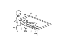
すなわち、表示装置部11に於いて、画像は制御部20によって表示制御部21を介してプロジェクタ13により投影され、ミラー14で反射されたスクリーン15に表示される。ここで、プロジェクタ13により投影される画像は、カメラ31から取得された画像そのものではなく、そのカメラ31の画像を含んだ画像である。加えて、プロジェクタ13から投影された画像は、図2に示されるように、カメラ31の近傍に見えるようにレイアウトされたものとなっている。
That is, in the
上記スクリーン15上のタッチパネル16は、カメラ31の位置も検出できるようになっていて、カメラ31から取得された画像データに対応した画像は、カメラ31の近くに表示されるように制御される。また、この場合、図2に示されるように、所定の位置にアルバム保存用の記録領域26aが設けられている。ユーザ30が、スクリーン15上の任意の画像33を指でドラッグして、上記記録領域26aの位置に持ってくると、当該画像がアルバム用の記録部26に記録できるようにしている。この際、カメラ31から記録領域26aに、画像33が流れるように移動される。例えば、複数の画像が移動される場合は、スライド表示のように順次カメラ33から記録領域26aに向かって移動される。このような応用も可能である。
The
このようなドラッグ機能を実現するため、スクリーン15には、ユーザの指の位置を検出するべく、タッチパネルの押されている位置を検出して判定する操作判定部24を有している。この操作判定部24でタッチパネル16が押されていると判定された場合は、制御部20は、その判定結果に基づいて、あたかも画像33がスクリーン15上で引き摺られていくように、表示制御部21を制御して表示を切り替える。
In order to realize such a drag function, the
また、画像33をアルバムに保存する際には、記録部26に、画像33に対応した画像データを記録できるように制御を行う。つまり、制御部20は、カメラ31の位置やユーザ30による操作入力を、タッチパネル16と位置検出部23及び操作判定部24によって検出する。そして、通信部25によって入力された画像データを、上述したカメラ31等の機器の位置や上述した操作に従って取り込み、表示制御部21を制御することにより、上述の操作に従った位置に対応する画像を表示する。
When the
図3は、こうした制御部20がコントロールするプログラムに従った動作を説明するフローチャートである。
FIG. 3 is a flowchart for explaining the operation according to the program controlled by the
テーブル型スクリーン装置10の図示されない電源スイッチがオンされると、ステップS1に於いて、スクリーン15上にカメラ30が載置されたか否かが判定される。ユーザ30がカメラ31をテーブル状スクリーン15の上に載置すると、その時の押圧力の変化からカメラが載置されたことが検出される。すると、タッチパネル16の押圧された位置に応じて、ステップS2にてカメラ位置が位置検出部23により検出される。
When a power switch (not shown) of the table
次いで、ステップS3にて、通信部25によってカメラ31内のデータの読み出しが行われる。そして、ステップS4にて、上記ステップS2で検出されたカメラ位置付近に、その時読み出されたデータに対応した画像が再生されるべく投影されるように、表示制御部21が制御される。
Next, in step S3, data in the
その後、ステップS5に於いて、ユーザ30の操作の有無が判定される。ここで、特に操作されなければ本ルーチンが終了する。一方、何らかの操作がなされたならば、ステップS6へ移行して、それぞれの処理動作が行われる。
Thereafter, in step S5, it is determined whether or not the
つまり、タッチパネル16の押された状態や、押された位置の変化が判定されるが、例えばステップS6に於いては、所定画像のダブルクリック(ダブルタップ)が判定される。ここで、ダブルクリックがなされない場合は、後述するステップS10へ移行し、ダブルクリックがなされた場合は、ステップS7へ移行して拡大前画像であるか否かが判定される。
That is, the pressed state of the
ここで、拡大前画像である場合は、ステップS9へ移行して拡大表示が行われる。一方、拡大前画像ではない、すなわち拡大後画像と判定された場合には、ステップS8へ移行して、縮小表示が行われる。このように、ステップS8またはS9にて、ユーザ30が画像拡大によるチェックや鑑賞、画像縮小による整理等、好みの大きさでの扱いができるように工夫されている。これは、制御部20が表示制御部21を制御して行うが、全体画面の中で、上述した所定画像が占める割合を大きくして表示すればよい。
Here, in the case of the pre-enlargement image, the process proceeds to step S9 and an enlarged display is performed. On the other hand, when it is determined that the image is not the pre-enlargement image, that is, the post-enlargement image, the process proceeds to step S8 and the reduced display is performed. In this way, in step S8 or S9, the
ステップS10に於いては、指でテーブル状スクリーン15上をなぞって、それが所定の画像の位置から別位置にずれていく、すなわち操作位置が移動したか否かが判定される。ここで、移動しなければ後述するステップS12へ移行し、移動される場合は、ステップS11へ移行する。
In step S10, it is determined whether the finger is traced on the table-
ステップS11では、その画像を上記別位置に移動させるような表示位置切り替えが行われる。そして、その移動先が、図2に記録領域26aとして示されるようなアルバム部であれば、ステップS12に於いて移動先が判定される。ここで、移動先が記録領域26aであれば、ステップS13へ移行して記録領域26aに画像データが記録される。
In step S11, the display position is switched so that the image is moved to the different position. If the destination is an album part as shown in FIG. 2 as the
図4は、このようにして作成されたアルバムの例を示したものである。ここでは、テーブル型のスクリーン装置の記録部26に作られた、電子アルバムの表示形態の一例として示している。
FIG. 4 shows an example of an album created in this way. Here, an example of a display form of an electronic album created in the
このように、移動された画像がテーブル上に載置された簡易アルバム26bのように表示され、全く、紙のアルバムと違いのない表示とすることができる。この場合、ユーザ30が三角スイッチ部16aまたは16bをタッチすると、ページの送り戻りができ、アルバム26bの鑑賞が可能となる。このアルバム26bも、ドラッグ動作でテーブル上の任意の位置に表示位置切り替えが可能である。
In this way, the moved image is displayed like a
また、プリント(PRINT)釦16cが押されると、プリント出力吐出口27a(図2参照)から、用紙に記録された画像がプリントアウトされる。
When the print (PRINT)
尚、上記ステップS12に於いて記録先が記録領域26aでない場合、及びステップS13にて記録終了後は、上記ステップS5へ移行して、以降の処理動作が繰り返される。
When the recording destination is not the
また、通信部25の通信方法としては、光通信も考えられるが、指向性がない方が好ましいので、ブルートゥース等、微弱な電波を用いた通信を行う方が好ましい。
As a communication method of the
更に、タッチパネル16は、例えば、図5に示されるような構成としてもよい。
Furthermore, the
すなわち、P1 〜P12のような透明電極で構成される複数のスイッチをスクリーン15上に設け、その何れのスイッチが押されてONされているかを判定するようにしてもよい。つまり、スイッチ制御部41によって、時系列で順次スイッチ部42a、42b内の各スイッチをオン/オフしていき、この時通電するか否かを、電流計43aの出力結果等で検出部43bが判定検出すれば、何れのスイッチ(何れの場所)が押されているかを判定することができる。
That is, a plurality of switches composed of transparent electrodes such as P 1 to P 12 may be provided on the
例えば、スイッチP1 の位置に指や機器が置かれてスイッチがオンされている場合は、スイッチ部42aのスイッチS1と、スイッチ部42bのスイッチSAがオンした時に、電流計43aにて電流が検出される。
For example, when a finger or a device is placed at the position of the switch P 1 and the switch is turned on, when the switch S1 of the
ここでは、スイッチP1 〜P12の12個のスイッチで簡単化したが、実際にはこのようなスイッチが無数に敷き詰められているものとする。 Here, the simplification is made with twelve switches P 1 to P 12 , but in reality, it is assumed that an infinite number of such switches are laid.
また、上述した表示装置部11を、図6に示されるような構成としてもよい。
Further, the
すなわち、表示装置部11′に於いて、指によって押されると反射が変化するようなパネル16′をスクリーン15の上に配置すると共に、プロジェクタ13の光をスクリーン15に導くミラーをハーフミラー14aまたは波長伝導性のあるミラーで構成する。これにより、上記反射の変化による陰影の変化が、受光レンズ45を介した撮像素子46で検出されて、指の位置が検出されるようになっている。
That is, in the
勿論、上述した第1の実施形態による表示装置部11は、図5に示されるタッチパネルと、図6に示される表示装置部11′の両方を組み合わせたもので構成されるようにしてもよい。
Of course, the
このようなタッチパネル式スクリーンを利用することによって、機器や指の位置を判定することができる。機器であるか指であるかは、押されている部分の範囲の大きさや形状、或いは上述した通信部25の通信結果に従って判定される。
By using such a touch panel screen, the position of the device or the finger can be determined. Whether the device is a device or a finger is determined according to the size and shape of the range of the pressed portion or the communication result of the
つまり、図5に示されるタッチパネルの例では、指であれば押されているスイッチの数が少なく、ドラッグ時等、時間による変化がある。一方、カメラ31が載置されている場合は、押されているスイッチの数が多く、時間による変化がない上に、通信部25と所定の通信が成立する。
That is, in the example of the touch panel shown in FIG. 5, the number of switches being pressed is small for a finger, and there is a change with time such as when dragging. On the other hand, when the
(第2の実施形態)
次に、本発明の第2の実施形態を説明する。
(Second Embodiment)
Next, a second embodiment of the present invention will be described.
上述した第1の実施形態では、スクリーン上には1つの機器(カメラ)が載置された場合の例について説明したが、この第2の実施形態では、スクリーン上に複数の機器が載置された場合の例について説明する。 In the first embodiment described above, an example in which one device (camera) is placed on the screen has been described. However, in the second embodiment, a plurality of devices are placed on the screen. An example of the case will be described.
図7は、本発明の第2の実施形態によるデジタルプラットフォーム装置の構成を示した図である。 FIG. 7 is a diagram illustrating a configuration of a digital platform apparatus according to the second embodiment of the present invention.
尚、以下に述べる実施形態に於いては、デジタルプラットフォーム装置の構成及び基本的な動作については、図1乃至図6に示される第1の実施形態と同じであるので、これらの構成及び動作については、同一の部分には同一の参照番号を付して、その図示及び説明は省略するものとし、異なる構成及び動作についてのみ説明する。 In the embodiment described below, the configuration and basic operation of the digital platform device are the same as those in the first embodiment shown in FIGS. The same parts are denoted by the same reference numerals, illustration and description thereof are omitted, and only different configurations and operations will be described.
例えば、スクリーン15上に撮影画像データが記録されたカメラ31と、プリンタ35が載置されている場合について考える。すると、プリンタ35から正しい画像プリントを得るためには、送信装置としてのカメラ31内の画像が、図7に示されるようにスクリーン15上に表示(画像33)される。そのうち、選択された1枚(33a)のみが、受信装置としてのプリンタ35の中に入っていく形式でデータの授受が表示されるので、誤ってユーザが考えていた写真と異なる画像をプリントしてしまうことを防止することができる。
For example, consider a case where a
このような実施形態を実現するために、第2の実施形態では、カメラ31やプリンタ35が、ワイヤレスでテーブル型スクリーン15の通信部25と通信するようにし、該通信部25と制御部20との間に機器の種別を判定する機器種別判定部24aを設けた構成としている。
In order to realize such an embodiment, in the second embodiment, the
これは、各機器が、その機能を示す信号を送信するようにし、位置検出部23によって、各々の機器の位置が検出できるようにすることによって、簡単に実現することができる。
This can be easily realized by allowing each device to transmit a signal indicating its function and allowing the
例えば、図7に示されるような位置にカメラ31が載置された場合は、その近傍に画像33が表示される。また、ユーザがその画像33のうち1枚をドラッグすれば、指の移動に従って画像33aのように、場所を移動させる形で表示する。そして、表示制御部21によるその移動場所が、プリンタ35の近くまで来たことが判定されれば、ユーザはプリンタ35でその画像を印刷したいと考えていると判定される。制御部20は表示制御部21を介して画像データをプリンタ35に送信し、プリンタ35はその送られたデータに対応した画像をプリントアウトする。
For example, when the
また、図7に於いては画像33aが示されているだけであるが、プリンタ35の近傍にもカメラ31から得た画像を表示することも可能であることは勿論である。
In FIG. 7, only the
このように、ユーザが選択した写真画像を、間違いなくプリントアウトするには、どの位置にどの画像データを表示したかを制御部20が常に把握している必要がある。
As described above, in order to print out the photographic image selected by the user without fail, the
図8は、第2の実施形態のデジタルプラットフォーム装置による画像データ表示動作を説明するフローチャートである。以下、このフローチャートを参照して、その画像表示位置把握の方法について説明する。 FIG. 8 is a flowchart illustrating an image data display operation performed by the digital platform device according to the second embodiment. Hereinafter, a method of grasping the image display position will be described with reference to this flowchart.
先ず、ステップS21にて、サブルーチン“カメラ位置検出PC ”が実行され、続いてステップS22にてサブルーチン“プリンタ位置検出PP ”が実行される。尚、これらのステップS21及びS22の各サブルーチンの詳細については後述する。 First, in step S21, the subroutine “camera position detection P C ” is executed, and then in step S22, the subroutine “printer position detection P P ” is executed. Details of these subroutines of steps S21 and S22 will be described later.
次いで、ステップS23にて、検出されたカメラ31の位置PC の前方Lのスクリーン位置P1 〜P3 に、図7に示されるように、カメラ31から読み出された画像データが再生されて、画像33が3枚並べられる。更に、続くステップS24にて、その前方の距離Lの位置P4 〜P6 に、別の撮影画像が表示される。尚、この距離Lは、画像の縦サイズ相当である。
Next, in step S23, the image data read from the
このように、制御部20では、先ずカメラ位置が考慮されて、表示位置が決定されている。
As described above, the
次に、ステップS25に於いて、この表示位置上に押圧があったか否かが判定される。ここで、上記押圧がほぼ指の先端の大きさや形状に相当する場合、表示位置に指の押圧があったと判定されて、ステップS26へ移行する。この押圧部分は逐次モニタされているもので、ステップS26に於いて、それが移動したか否かが判定される。 Next, in step S25, it is determined whether or not there is a press on the display position. Here, if the above-mentioned pressing substantially corresponds to the size or shape of the tip of the finger, it is determined that the finger is pressed at the display position, and the process proceeds to step S26. This pressed portion is monitored sequentially, and it is determined in step S26 whether or not it has moved.
上記ステップS26で画像の移動が無い場合、または上記ステップS25にて押圧が無い場合は、上記ステップS25へ移行する。これに対し、上記ステップS25で押圧が有り、ステップS26で画像が移動したと判定された場合は、ステップS27へ移行して、上記移動に従って、その部分に表示されていた画像も移動される。そして、続くステップS28にて、移動のたびに何れの画像が何れの位置P7 にずらされて表示されているかが、対応付けられる。 If there is no movement of the image in step S26 or if there is no press in step S25, the process proceeds to step S25. On the other hand, if it is determined in step S25 that there is a press and it is determined in step S26 that the image has moved, the process proceeds to step S27, and the image displayed in that portion is also moved in accordance with the movement. Then, at the subsequent step S28, one of the image each time the movement is displayed in staggered position P 7 either it is associated.
この対応付けの結果、ステップS29に於いて、その位置と上記ステップS21で検出されたプリンタ位置PP が所定の距離範囲内であるか否かが判定される。ここで、上記所定の距離範囲内に無い場合は上記ステップS25へ移行する。一方、上記所定距離内にプリンタ位置PP がある場合には、ステップS30へ移行する。 This association results in step S29, the printer position P P detected at that position and the step S21 whether or not within a predetermined distance range is determined. If the distance is not within the predetermined distance range, the process proceeds to step S25. On the other hand, if there is a printer location P P is within the predetermined distance, the process proceeds to step S30.
ステップS30では、画像33aがプリンタ35の中に吸い込まれて入っていくようなイメージを表現するために、表示位置シフトが行われる。次いで、ステップS31にて、その表示画像に対応するデジタル画像データがプリンタ35に入力される。更に、ステップS32では、プリンタ35に入力された画像をプリントアウトする命令が送信される。これによって、プリンタ35は、送信されてきた画像データを画像として印刷する。
In step S30, a display position shift is performed in order to express an image in which the
このように、ユーザは、カメラの中の撮影画像データのうち、気に入ったものを、あたかもそこに写真があるような感覚で選択して、確実にプリンタから画像をプリントアウトすることができる。 In this way, the user can select a favorite image of the captured image data in the camera as if there is a photograph, and can reliably print out the image from the printer.
次に、図9を参照して、第2の実施形態によるデジタルプラットフォーム装置に於ける各機器の検出の方法について説明する。 Next, with reference to FIG. 9, a method of detecting each device in the digital platform apparatus according to the second embodiment will be described.
テーブル型スクリーン装置10のタッチパネル式のスクリーン15上に、底面が四角形状でΔxc ×Δyc のカメラ31が載置されると、その範囲(Δxc ×Δyc)でタッチパネルが押される。例えば、図5に示される構成のスイッチで説明すると、その底面に基づいてスイッチがオンされるので、このオンされたスイッチの範囲から、図10のフローチャートに従ってカメラの位置を検出することができる。
When the
図10は、図8のフローチャートのステップS21に於けるサブルーチン“カメラ位置検出PC ”の動作を説明するフローチャートである。 FIG. 10 is a flowchart for explaining the operation of the subroutine “camera position detection P C ” in step S21 of the flowchart of FIG.
本サブルーチンに入ると、先ず、ステップS41にて、オンされたスイッチP1 〜P12のうち、上記Δxc ×Δycの範囲でオンされている部分が検出される。そして、ステップS42に於いて、上記範囲内でオンされている部分の有無が判定される。ここで、オンされている部分が無ければ上記ステップS41へ移行する。一方、オンされている部分があったならば、ステップS43へ移行する。 When this subroutine is entered, first, in step S41, a portion that is turned on in the range of Δx c × Δy c among the turned-on switches P 1 to P 12 is detected. In step S42, it is determined whether or not there is a portion that is turned on within the above range. If there is no portion that is turned on, the process proceeds to step S41. On the other hand, if there is a part that is turned on, the process proceeds to step S43.
このステップS43では、そのオンされたスイッチ範囲のうち、重心位置座標xc ,yc が、カメラ位置PC とされる。但し、このスイッチ範囲に載置されたものがカメラ以外の箱である可能性もあるので、続くステップS44に於いて、通信部25がカメラ31と適切なハンドシェイクとされたか否かが確認される。
In this step S43, the center-of-gravity position coordinates x c and y c in the turned-on switch range are set as the camera position P C. However, since there is a possibility that what is placed in this switch range is a box other than the camera, it is confirmed in the subsequent step S44 whether or not the
ここで、カメラでないと判定された場合は、上記ステップS41へ移行する。一方、カメラであると判定された場合は、ステップS45へ移行してカメラ位置PC が決定される。その後、本サブルーチンを抜ける。 If it is determined that the camera is not used, the process proceeds to step S41. On the other hand, if it is determined that the camera, the camera position P C is determined, the process proceeds to step S45. Then, this subroutine is exited.
また、プリンタ35は、例えば図9に示されるように、その底面に4箇所、脚部35aが設けられており、その幅と奥行きがΔxp 、Δyp ならば、その各件を満たすパネル上押圧部があるか否かで、プリンタ位置が判定される。
The
図11は、図8のフローチャートのステップS22に於けるサブルーチン“プリンタ位置検出PP ”の動作を説明するフローチャートである。 FIG. 11 is a flowchart for explaining the operation of the subroutine “printer position detection P P ” in step S22 of the flowchart of FIG.
本サブルーチンに入ると、先ず、ステップS51に於いて、4つの脚部35aの押圧条件の有無が判定される。ここで、4箇所の押圧部がある場合は、続くステップS52に於いて、脚部35aの距離が所定条件を満たしているか否かが判定される。ここで、上記ステップS51で4箇所の押圧部が無い場合、または上記ステップS52にて脚部35aの距離が所定条件を満たしていない場合は、上記ステップS51へ移行する。
When this subroutine is entered, first, at step S51, it is determined whether or not there are pressing conditions for the four
一方、上記ステップS51及びS52にて、4箇所の押圧部が有り、且つ、脚部35aの距離が所定条件を満たして入る場合は、ステップS53へ移行する。このステップS53では、上記4箇所の脚部35aを四つの角とする四角形の重心位置の座標xp 、yp が検出され、その位置がプリンタの位置とされる。
On the other hand, when there are four pressing portions in steps S51 and S52 and the distance of the
但し、図10のフローチャートのステップS44と同様に、上記重心位置に載置されたものがプリンタでない場合もあるので、ステップS54に於いて、プリンタと通信可能であるか否かが判定される。その結果、通信可能であれば、プリンタに間違いないとして、ステップS55に移行し、プリンタ位置PP が確定される。一方、上記ステップS54にてプリンタでないと判定された場合は、上記ステップS51へ移行する。 However, as in step S44 of the flowchart of FIG. 10, there is a case where the one placed at the center of gravity is not a printer, so in step S54, it is determined whether or not communication with the printer is possible. As a result, if communication is possible, it is determined that the printer is correct, the process proceeds to step S55, and the printer position PP is determined. On the other hand, if it is determined in step S54 that the printer is not a printer, the process proceeds to step S51.
尚、ここでは、カメラとプリンタを例として説明したが、カメラから大容量記録手段であるストレージに画像入力する場合や、カメラのデータをプロジェクタ等で投影表示するような場合も、同様の方法で、位置検出と通信を駆使してデータの授受を確実に行うことができる。 Although a camera and a printer have been described as examples here, the same method is used when inputting an image from a camera to a storage, which is a large-capacity recording unit, or when projecting and displaying camera data with a projector or the like. Data can be reliably exchanged using position detection and communication.
例えば、図12に示されるように、送信装置であるストレージ50に蓄積されている画像を、受信装置であるプロジェクタ51によってスクリーン上に表示し、適宜、プロジェクタ51で画像52を拡大撮影することもできる。この場合、例えばスクリーン上に表示される画像33は、ストレージ50の近傍であって、プロジェクト51の近傍であってもよい。或いは、ストレージ50及びプロジェクト51の両者の近傍に表示されるようにしてもよい。
For example, as shown in FIG. 12, an image stored in the
また、図9乃至図11に示されるカメラ位置検出及びプリンタ位置検出では、タッチパネル機能を利用したが、スクリーン上の個々の機器を区別するには、次のような例も考えられる。 Further, in the camera position detection and the printer position detection shown in FIGS. 9 to 11, the touch panel function is used, but the following examples are also conceivable in order to distinguish individual devices on the screen.
すなわち、図13(a)に示されるように、カメラ31等の下面部に、2次元バーコード31aを設けてもよい。また、図13(b)に示されるように、カメラ31の下面部に、ICタグ31bを設けてもよい。更には、図13(c)に示されるように、カメラ31の下面部に、赤外線通信器31cを設けるようにしてもよい。
That is, as shown in FIG. 13A, a two-
このように、種々の応用変形例が考えられる。 As described above, various application modifications can be considered.
図14は、例えば、図13(a)に示されるような、バーコード31aを読み取るタイプのデジタルプラットフォーム装置に於けるカメラの位置検出システムの構成例を示した図である。
FIG. 14 is a diagram showing a configuration example of a camera position detection system in a digital platform device of a type that reads a
ここでは、スクリーン15aをLCDで構成し、LCD制御回路15bによって、このLCDを透過または光拡散式のスクリーン15aを電気的に切り替え可能なようにしている。つまり、カメラ31の下面部のバーコードの読み取り時には、LCD15aを透過にし、プロジェクタ13の光をハーフミラー14でバーコード31aに照射する。そして、その反射光を受光レンズ45とモニタ用撮像素子(センサ)46で検出するようにしている。
Here, the
図15は、こうした構成のカメラの位置検出システムによるバーコード検出の動作を説明するフローチャートである。 FIG. 15 is a flowchart for explaining an operation of barcode detection by the camera position detection system having such a configuration.
本ルーチンに入ると、先ず、ステップS61にてLCD15aが透過にされる。次いで、ステップS62にて、プロジェクタ13から均一な光が投射されると、ハーフミラー14aで反射されてカメラ31の下面部に配置されたバーコード31aに導かれる。
When entering this routine, first, the
そして、ステップS63にて、バーコード31aで反射された光がハーフミラー14aを透過し、受光レンズ45を介して撮像素子46によって読み取られる。これにより、カメラ31の位置が検出される。ここで、ステップS64にて、通信部(図1参照)によってカメラ31と通信が行われる。
In step S 63, the light reflected by the
次いで、ステップS65では、プロジェクタ13の出力画像が表示可能なように、LCD制御回路15bによって、LCD15aが光拡散モードに切り替えられる。その後、ステップS66にて、カメラ31の近傍にカメラ31内の画像を再生表示するべくプロジェクタ13から投影される。
Next, in step S65, the
以上説明したように、第2の実施形態によれば、画像データ用の電波による通信手段以外に機器を検出するコード検出によって、より正確に機器情報とその位置を判定することができる。 As described above, according to the second embodiment, device information and its position can be determined more accurately by code detection that detects a device other than the communication means using radio waves for image data.
また、上述した第1及び第2の実施形態では、表示機能付きのテーブルの上に機器を載置した例で説明したが、これに限られるものではない。 In the first and second embodiments described above, the example is described in which the device is placed on the table with the display function. However, the present invention is not limited to this.
例えば、図16に示されるように、フラットパネルディスプレイ10aを一般的なテーブル10b上に立てる。この状態で、テーブル10b上にカメラ31やプリンタ35が載置されると、通信部25a及び25bによって各々の機器が判定される。すると、カメラ31の内部メモリに記録されている画像データは、フラットパネルディスプレイ10a上の仮想テーブル10c上に、画像33として図示の如く表示される。
For example, as shown in FIG. 16, the
このように構成しても、上述した第1及び第2の実施形態と同様の効果を得ることも可能である。この例では、特別なテーブル構成のディスプレイを用いなくとも、本発明の目的を達成することができる。 Even if comprised in this way, it is also possible to acquire the effect similar to 1st and 2nd embodiment mentioned above. In this example, the object of the present invention can be achieved without using a display with a special table configuration.
上述した実施形態によれば、機器に入っている画像を直接的に表示することができ、画像データ転送時には、その転送経過に、当該画像をユーザに明示することができるので、画像信号の取り扱いを失敗することなく、確実な送信、受信が可能となる。 According to the above-described embodiment, the image stored in the device can be directly displayed, and when transferring image data, the image can be clearly shown to the user during the transfer process. Can be reliably transmitted and received without failure.
以上、本発明の実施形態について説明したが、本発明は上述した実施形態に限定されるものではなく、本発明の要旨を逸脱しない範囲で種々の変形実施が可能であるのは勿論である。 Although the embodiments of the present invention have been described above, the present invention is not limited to the above-described embodiments, and various modifications can be made without departing from the scope of the present invention.
10…テーブル型スクリーン装置、11…表示装置部、13…プロジェクタ、14…ミラー、14a…ハーフミラー、15…スクリーン、16…タッチパネル、16a、16b…三角スイッチ部、20…制御部、21…表示制御部、23…位置検出部、24…操作判定部、25…通信部、26…記録部、26a…記録領域、26b…アルバム、27…プリンタ、27a…プリント出力吐出口、30…ユーザ、31…カメラ、ユーザ30が、33…画像、35…プリンタ、41…スイッチ制御部、42a、42b…スイッチ部、43a…電流計、43b…検出部、45…受光レンズ、46…撮像素子。
DESCRIPTION OF
Claims (18)
上記送信装置と上記受信装置の置かれた位置をそれぞれ検出する位置検出手段と、
所定の命令操作に応じて、上記送信装置から上記受信装置への画像データ転送を制御する制御手段と、
上記画像データの転送に際して、当該転送画像を上記平面部に表示する表示手段と、
を具備し、
上記制御手段は、上記送信装置に記録された全画像データを上記送信装置の近傍に縮小表示させ、上記所定の操作により指定された画像データを上記受信装置に転送する際に、これら転送される画像データの縮小画像を上記受信装置の近傍に表示させることを特徴とするデジタルプラットフォーム装置。 A digital platform device having a plane unit on which image data is stored and a transmitting device capable of transmitting the stored image data and a receiving device capable of receiving the image data are respectively mounted.
Position detecting means for detecting the positions of the transmitting device and the receiving device, respectively;
Control means for controlling image data transfer from the transmitting device to the receiving device in accordance with a predetermined command operation;
Display means for displaying the transferred image on the flat surface when transferring the image data;
Comprising
The control means reduces all the image data recorded on the transmission device in the vicinity of the transmission device, and transfers the image data designated by the predetermined operation when the image data is transferred to the reception device. A digital platform device that displays a reduced image of image data in the vicinity of the receiving device.
上記画像データを受信する受信手段と、
上記画像データを上記送信手段から受信手段に転送制御する制御手段と、
を有するデジタルプラットフォーム装置に於いて、
上記制御手段は、上記送信手段と受信手段の位置を検出する検出手段と、上記画像データを表示する表示手段とを有することを特徴とするデジタルプラットフォーム装置。 A transmission means for transmitting image data;
Receiving means for receiving the image data;
Control means for controlling transfer of the image data from the transmitting means to the receiving means;
In a digital platform device having
The digital platform apparatus, wherein the control means includes detection means for detecting positions of the transmission means and the reception means, and display means for displaying the image data.
上記表示手段は、上記操作判定手段の判定したユーザの操作結果に基づいて、上記画像データを上記受信手段に入力することを特徴とする請求項4に記載のデジタルプラットフォーム装置。 The control means further includes an operation determination means for detecting a user operation,
5. The digital platform apparatus according to claim 4, wherein the display unit inputs the image data to the receiving unit based on a user operation result determined by the operation determining unit.
上記画像データを受信可能な受信装置と、
上記受信装置で受信された上記画像データに対応した画像を投影する投影手段と、
上記送信装置及び上記受信装置を載置すると共に上記投影手段で投影された画像を表示する表示手段と、
上記表示手段上に載置された上記送信装置及び上記受信装置の位置をそれぞれ検出する位置検出手段と、
所定の操作に応じて上記送信装置から上記受信装置への画像データ転送を制御するもので、上記送信装置に記録された全画像データに対応した画像を上記位置検出手段で検出された上記送信装置の近傍に表示させ、上記所定の操作により指定された画像データを上記受信装置に転送する際に、これら転送される画像データに対応した画像を上記位置検出手段で検出された上記受信装置の近傍に表示させるように上記投影手段を制御する制御手段と、
を具備することを特徴とするデジタルプラットフォーム装置。 A transmission device for storing image data and capable of transmitting the stored image data;
A receiving device capable of receiving the image data;
Projecting means for projecting an image corresponding to the image data received by the receiving device;
Display means for mounting the transmitting apparatus and the receiving apparatus and displaying an image projected by the projection means;
Position detecting means for respectively detecting the positions of the transmitting device and the receiving device placed on the display means;
The transmission device which controls image data transfer from the transmission device to the reception device according to a predetermined operation, and which has detected an image corresponding to all image data recorded in the transmission device by the position detection means When the image data designated by the predetermined operation is transferred to the receiving device, the image corresponding to the transferred image data is detected by the position detecting means in the vicinity of the receiving device. Control means for controlling the projection means to display on
A digital platform device comprising:
上記制御手段は、上記操作判定手段で判定されたユーザの操作結果に基づいて、上記画像データを上記送信装置から上記受信装置に転送させることを特徴とする請求項8に記載のデジタルプラットフォーム装置。 It further comprises operation determining means for detecting and determining a user operation,
9. The digital platform device according to claim 8, wherein the control unit causes the image data to be transferred from the transmission device to the reception device based on a user operation result determined by the operation determination unit.
上記画像データを受信する受信手段と、
上記送信手段及び上記受信手段の位置を検出する位置検出手段と、
上記位置検出手段で位置が検出された上記送信手段から上記受信手段に上記画像データを転送制御する制御手段と、
上記制御手段によって上記受信手段に転送された上記画像データに対応する画像を表示する表示手段と、
を具備することを特徴とするデジタルプラットフォーム装置。 A transmission means for transmitting image data;
Receiving means for receiving the image data;
Position detecting means for detecting positions of the transmitting means and the receiving means;
Control means for controlling transfer of the image data from the transmitting means whose position is detected by the position detecting means to the receiving means;
Display means for displaying an image corresponding to the image data transferred to the receiving means by the control means;
A digital platform device comprising:
上記制御手段は、上記操作判定手段で判定されたユーザの操作結果に基づいて、上記画像データを上記送信手段から上記受信手段に転送させることを特徴とする請求項13に記載のデジタルプラットフォーム装置。 It further comprises operation determining means for detecting and determining a user operation,
14. The digital platform device according to claim 13, wherein the control unit causes the image data to be transferred from the transmission unit to the reception unit based on a user operation result determined by the operation determination unit.
Priority Applications (2)
| Application Number | Priority Date | Filing Date | Title |
|---|---|---|---|
| JP2004371678A JP4664665B2 (en) | 2004-12-22 | 2004-12-22 | Digital platform device |
| US11/312,863 US7535489B2 (en) | 2004-12-22 | 2005-12-20 | Digital platform apparatus |
Applications Claiming Priority (1)
| Application Number | Priority Date | Filing Date | Title |
|---|---|---|---|
| JP2004371678A JP4664665B2 (en) | 2004-12-22 | 2004-12-22 | Digital platform device |
Related Child Applications (2)
| Application Number | Title | Priority Date | Filing Date |
|---|---|---|---|
| JP2008106102A Division JP2008276219A (en) | 2008-04-15 | 2008-04-15 | Digital platform device |
| JP2010260014A Division JP5372894B2 (en) | 2010-11-22 | 2010-11-22 | Digital platform device |
Publications (2)
| Publication Number | Publication Date |
|---|---|
| JP2006178205A true JP2006178205A (en) | 2006-07-06 |
| JP4664665B2 JP4664665B2 (en) | 2011-04-06 |
Family
ID=36595085
Family Applications (1)
| Application Number | Title | Priority Date | Filing Date |
|---|---|---|---|
| JP2004371678A Expired - Fee Related JP4664665B2 (en) | 2004-12-22 | 2004-12-22 | Digital platform device |
Country Status (2)
| Country | Link |
|---|---|
| US (1) | US7535489B2 (en) |
| JP (1) | JP4664665B2 (en) |
Cited By (7)
| Publication number | Priority date | Publication date | Assignee | Title |
|---|---|---|---|---|
| JP2011238064A (en) * | 2010-05-11 | 2011-11-24 | Canon Inc | Display control apparatus and display control method |
| JP2011244023A (en) * | 2010-05-13 | 2011-12-01 | Canon Inc | Display control device and display control method |
| WO2012157653A1 (en) * | 2011-05-17 | 2012-11-22 | 三洋電機株式会社 | Charging display device |
| WO2015098189A1 (en) * | 2013-12-27 | 2015-07-02 | ソニー株式会社 | Display control device, display control method, and program |
| WO2017056658A1 (en) * | 2015-09-30 | 2017-04-06 | ソニー株式会社 | Information processing device, information processing method, and program |
| WO2018138885A1 (en) * | 2017-01-27 | 2018-08-02 | 富士通株式会社 | Information processing method, information processing program, and information processing device |
| JP2020140230A (en) * | 2019-02-26 | 2020-09-03 | 株式会社リコー | Information processing apparatus, information processing method and information processing program |
Families Citing this family (22)
| Publication number | Priority date | Publication date | Assignee | Title |
|---|---|---|---|---|
| JP4933304B2 (en) * | 2006-10-16 | 2012-05-16 | キヤノン株式会社 | Image processing apparatus, control method thereof, and program |
| JP4973245B2 (en) * | 2007-03-08 | 2012-07-11 | 富士ゼロックス株式会社 | Display device and program |
| JP2009033596A (en) * | 2007-07-30 | 2009-02-12 | Panasonic Corp | Remote control transmitter |
| US9134904B2 (en) | 2007-10-06 | 2015-09-15 | International Business Machines Corporation | Displaying documents to a plurality of users of a surface computer |
| US8139036B2 (en) * | 2007-10-07 | 2012-03-20 | International Business Machines Corporation | Non-intrusive capture and display of objects based on contact locality |
| US20090091539A1 (en) * | 2007-10-08 | 2009-04-09 | International Business Machines Corporation | Sending A Document For Display To A User Of A Surface Computer |
| US20090091529A1 (en) * | 2007-10-09 | 2009-04-09 | International Business Machines Corporation | Rendering Display Content On A Floor Surface Of A Surface Computer |
| US8024185B2 (en) * | 2007-10-10 | 2011-09-20 | International Business Machines Corporation | Vocal command directives to compose dynamic display text |
| US9203833B2 (en) * | 2007-12-05 | 2015-12-01 | International Business Machines Corporation | User authorization using an automated Turing Test |
| WO2009150786A1 (en) * | 2008-06-09 | 2009-12-17 | 株式会社村田製作所 | Elastic surface wave device, and manufacturing method therefor |
| US20100013738A1 (en) * | 2008-07-15 | 2010-01-21 | Edward Covannon | Image capture and display configuration |
| US9218116B2 (en) * | 2008-07-25 | 2015-12-22 | Hrvoje Benko | Touch interaction with a curved display |
| US8650634B2 (en) * | 2009-01-14 | 2014-02-11 | International Business Machines Corporation | Enabling access to a subset of data |
| US8446367B2 (en) * | 2009-04-17 | 2013-05-21 | Microsoft Corporation | Camera-based multi-touch mouse |
| US8610924B2 (en) | 2009-11-24 | 2013-12-17 | International Business Machines Corporation | Scanning and capturing digital images using layer detection |
| US8441702B2 (en) | 2009-11-24 | 2013-05-14 | International Business Machines Corporation | Scanning and capturing digital images using residue detection |
| JP5560721B2 (en) * | 2010-01-12 | 2014-07-30 | セイコーエプソン株式会社 | Image processing apparatus, image display system, and image processing method |
| KR101714050B1 (en) * | 2010-11-01 | 2017-03-08 | 삼성전자주식회사 | Device and method for displaying data in wireless terminal |
| JP2012215963A (en) * | 2011-03-31 | 2012-11-08 | Hitachi Consumer Electronics Co Ltd | Image display apparatus |
| US20120320226A1 (en) * | 2011-06-14 | 2012-12-20 | Chee Meng Chen | Stationary printing apparatus with camera |
| US9690396B1 (en) * | 2011-12-15 | 2017-06-27 | Brian R. Kubica | Paperless blueprint drafting table system |
| US20180224942A1 (en) * | 2017-02-03 | 2018-08-09 | International Business Machines Corporation | Method and system for navigation of content in virtual image display devices |
Citations (8)
| Publication number | Priority date | Publication date | Assignee | Title |
|---|---|---|---|---|
| JPH1157216A (en) * | 1997-08-15 | 1999-03-02 | Sony Corp | Game device |
| JP2001109570A (en) * | 1999-10-08 | 2001-04-20 | Sony Corp | System and method for inputting and outputting information |
| JP2004012712A (en) * | 2002-06-05 | 2004-01-15 | Olympus Corp | Table type display unit |
| JP2004164069A (en) * | 2002-11-11 | 2004-06-10 | Nippon Telegr & Teleph Corp <Ntt> | Information control system, information control method, program for the same, recording medium recording that program |
| JP2004262091A (en) * | 2003-02-28 | 2004-09-24 | Seiko Epson Corp | Printer |
| JP2004274152A (en) * | 2003-03-05 | 2004-09-30 | Canon Inc | Pico-net building method |
| JP2004282189A (en) * | 2003-03-13 | 2004-10-07 | Konica Minolta Holdings Inc | Image output system, printer, digital camera, display, and image output method |
| JP2004297509A (en) * | 2003-03-27 | 2004-10-21 | Minolta Co Ltd | Image forming apparatus |
Family Cites Families (1)
| Publication number | Priority date | Publication date | Assignee | Title |
|---|---|---|---|---|
| US7312817B2 (en) * | 2003-04-22 | 2007-12-25 | Hewlett-Packard Development Company, L.P. | Printer and docking station having a digital camera docking port with an image magnifier |
-
2004
- 2004-12-22 JP JP2004371678A patent/JP4664665B2/en not_active Expired - Fee Related
-
2005
- 2005-12-20 US US11/312,863 patent/US7535489B2/en not_active Expired - Fee Related
Patent Citations (8)
| Publication number | Priority date | Publication date | Assignee | Title |
|---|---|---|---|---|
| JPH1157216A (en) * | 1997-08-15 | 1999-03-02 | Sony Corp | Game device |
| JP2001109570A (en) * | 1999-10-08 | 2001-04-20 | Sony Corp | System and method for inputting and outputting information |
| JP2004012712A (en) * | 2002-06-05 | 2004-01-15 | Olympus Corp | Table type display unit |
| JP2004164069A (en) * | 2002-11-11 | 2004-06-10 | Nippon Telegr & Teleph Corp <Ntt> | Information control system, information control method, program for the same, recording medium recording that program |
| JP2004262091A (en) * | 2003-02-28 | 2004-09-24 | Seiko Epson Corp | Printer |
| JP2004274152A (en) * | 2003-03-05 | 2004-09-30 | Canon Inc | Pico-net building method |
| JP2004282189A (en) * | 2003-03-13 | 2004-10-07 | Konica Minolta Holdings Inc | Image output system, printer, digital camera, display, and image output method |
| JP2004297509A (en) * | 2003-03-27 | 2004-10-21 | Minolta Co Ltd | Image forming apparatus |
Cited By (10)
| Publication number | Priority date | Publication date | Assignee | Title |
|---|---|---|---|---|
| JP2011238064A (en) * | 2010-05-11 | 2011-11-24 | Canon Inc | Display control apparatus and display control method |
| JP2011244023A (en) * | 2010-05-13 | 2011-12-01 | Canon Inc | Display control device and display control method |
| WO2012157653A1 (en) * | 2011-05-17 | 2012-11-22 | 三洋電機株式会社 | Charging display device |
| WO2015098189A1 (en) * | 2013-12-27 | 2015-07-02 | ソニー株式会社 | Display control device, display control method, and program |
| JPWO2015098189A1 (en) * | 2013-12-27 | 2017-03-23 | ソニー株式会社 | Display control apparatus, display control method, and program |
| US11146771B2 (en) | 2013-12-27 | 2021-10-12 | Sony Corporation | Display control device, display control method, and program |
| WO2017056658A1 (en) * | 2015-09-30 | 2017-04-06 | ソニー株式会社 | Information processing device, information processing method, and program |
| WO2018138885A1 (en) * | 2017-01-27 | 2018-08-02 | 富士通株式会社 | Information processing method, information processing program, and information processing device |
| JP2020140230A (en) * | 2019-02-26 | 2020-09-03 | 株式会社リコー | Information processing apparatus, information processing method and information processing program |
| JP7275643B2 (en) | 2019-02-26 | 2023-05-18 | 株式会社リコー | Information processing device, information processing method and information processing program |
Also Published As
| Publication number | Publication date |
|---|---|
| JP4664665B2 (en) | 2011-04-06 |
| US7535489B2 (en) | 2009-05-19 |
| US20060132501A1 (en) | 2006-06-22 |
Similar Documents
| Publication | Publication Date | Title |
|---|---|---|
| JP4664665B2 (en) | Digital platform device | |
| US7705832B2 (en) | Image display apparatus, and image display method | |
| JP5657471B2 (en) | Digital platform device | |
| US7427983B1 (en) | Visual communication system | |
| US8016198B2 (en) | Alignment and non-alignment assist images | |
| US9544556B2 (en) | Projection control apparatus and projection control method | |
| US20150294645A1 (en) | Communication terminal, screen display method, and recording medium | |
| JP2008242367A (en) | Display-control device, display device, display system, and program | |
| JP2010092086A (en) | User input apparatus, digital camera, input control method, and input control program | |
| JP2008276219A (en) | Digital platform device | |
| JP2011054162A (en) | Interactive information control system and program | |
| JP4957327B2 (en) | Display control device | |
| JPH1195895A (en) | Information input device | |
| WO2011158401A1 (en) | Input device, evaluation method, and evaluation program | |
| JP5693022B2 (en) | Display control device, display control system, and control method, program, and storage medium thereof | |
| KR102295823B1 (en) | Method of providing an interface using a mobile device and a wearable device | |
| JP4589619B2 (en) | Paper document information operation system and information operation method | |
| JP5372894B2 (en) | Digital platform device | |
| JP2019092065A (en) | Image reading device and program | |
| JP5296144B2 (en) | Digital platform device | |
| JP2019091277A (en) | Display unit and program | |
| JP2019092064A (en) | Display and program | |
| JP2007017516A (en) | Projector provided with function of projecting two-dimensional positional information | |
| TW201443842A (en) | Method to set a navigation environment | |
| TW201435656A (en) | Information technology device input systems and associated methods |
Legal Events
| Date | Code | Title | Description |
|---|---|---|---|
| A621 | Written request for application examination |
Free format text: JAPANESE INTERMEDIATE CODE: A621 Effective date: 20070807 |
|
| A131 | Notification of reasons for refusal |
Free format text: JAPANESE INTERMEDIATE CODE: A131 Effective date: 20100921 |
|
| A521 | Request for written amendment filed |
Free format text: JAPANESE INTERMEDIATE CODE: A523 Effective date: 20101122 |
|
| TRDD | Decision of grant or rejection written | ||
| A01 | Written decision to grant a patent or to grant a registration (utility model) |
Free format text: JAPANESE INTERMEDIATE CODE: A01 Effective date: 20101221 |
|
| A01 | Written decision to grant a patent or to grant a registration (utility model) |
Free format text: JAPANESE INTERMEDIATE CODE: A01 |
|
| A61 | First payment of annual fees (during grant procedure) |
Free format text: JAPANESE INTERMEDIATE CODE: A61 Effective date: 20110107 |
|
| R151 | Written notification of patent or utility model registration |
Ref document number: 4664665 Country of ref document: JP Free format text: JAPANESE INTERMEDIATE CODE: R151 |
|
| FPAY | Renewal fee payment (event date is renewal date of database) |
Free format text: PAYMENT UNTIL: 20140114 Year of fee payment: 3 |
|
| S111 | Request for change of ownership or part of ownership |
Free format text: JAPANESE INTERMEDIATE CODE: R313111 |
|
| R350 | Written notification of registration of transfer |
Free format text: JAPANESE INTERMEDIATE CODE: R350 |
|
| S531 | Written request for registration of change of domicile |
Free format text: JAPANESE INTERMEDIATE CODE: R313531 |
|
| R350 | Written notification of registration of transfer |
Free format text: JAPANESE INTERMEDIATE CODE: R350 |
|
| R250 | Receipt of annual fees |
Free format text: JAPANESE INTERMEDIATE CODE: R250 |
|
| LAPS | Cancellation because of no payment of annual fees |