JP2006176558A - Method for preparing finely ground rubber - Google Patents
Method for preparing finely ground rubber Download PDFInfo
- Publication number
- JP2006176558A JP2006176558A JP2004368810A JP2004368810A JP2006176558A JP 2006176558 A JP2006176558 A JP 2006176558A JP 2004368810 A JP2004368810 A JP 2004368810A JP 2004368810 A JP2004368810 A JP 2004368810A JP 2006176558 A JP2006176558 A JP 2006176558A
- Authority
- JP
- Japan
- Prior art keywords
- rubber
- pulverization
- roll
- pulverizing
- coarse
- Prior art date
- Legal status (The legal status is an assumption and is not a legal conclusion. Google has not performed a legal analysis and makes no representation as to the accuracy of the status listed.)
- Granted
Links
- 229920001971 elastomer Polymers 0.000 title claims abstract description 219
- 239000005060 rubber Substances 0.000 title claims abstract description 219
- 238000000034 method Methods 0.000 title claims abstract description 23
- 239000002245 particle Substances 0.000 claims abstract description 72
- 238000000227 grinding Methods 0.000 claims abstract description 43
- 238000002156 mixing Methods 0.000 claims abstract description 27
- 239000003795 chemical substances by application Substances 0.000 claims abstract description 24
- 238000000926 separation method Methods 0.000 claims abstract description 22
- 238000010298 pulverizing process Methods 0.000 claims description 149
- 238000004519 manufacturing process Methods 0.000 claims description 32
- 230000008569 process Effects 0.000 claims description 19
- 239000002994 raw material Substances 0.000 claims description 15
- 238000011049 filling Methods 0.000 claims description 5
- 238000011084 recovery Methods 0.000 abstract 1
- 239000000843 powder Substances 0.000 description 22
- VTYYLEPIZMXCLO-UHFFFAOYSA-L Calcium carbonate Chemical compound [Ca+2].[O-]C([O-])=O VTYYLEPIZMXCLO-UHFFFAOYSA-L 0.000 description 8
- 230000002093 peripheral effect Effects 0.000 description 6
- 239000011148 porous material Substances 0.000 description 5
- 229910000019 calcium carbonate Inorganic materials 0.000 description 4
- 230000006835 compression Effects 0.000 description 4
- 238000007906 compression Methods 0.000 description 4
- 239000000463 material Substances 0.000 description 4
- 238000010008 shearing Methods 0.000 description 4
- 238000003860 storage Methods 0.000 description 4
- 239000010920 waste tyre Substances 0.000 description 4
- VYPSYNLAJGMNEJ-UHFFFAOYSA-N Silicium dioxide Chemical class O=[Si]=O VYPSYNLAJGMNEJ-UHFFFAOYSA-N 0.000 description 3
- 238000004898 kneading Methods 0.000 description 3
- 229920002209 Crumb rubber Polymers 0.000 description 2
- 230000009471 action Effects 0.000 description 2
- 230000008901 benefit Effects 0.000 description 2
- 238000005520 cutting process Methods 0.000 description 2
- 238000010586 diagram Methods 0.000 description 2
- 239000010419 fine particle Substances 0.000 description 2
- 238000009700 powder processing Methods 0.000 description 2
- 239000012779 reinforcing material Substances 0.000 description 2
- 239000000454 talc Substances 0.000 description 2
- 229910052623 talc Inorganic materials 0.000 description 2
- 230000002411 adverse Effects 0.000 description 1
- PNEYBMLMFCGWSK-UHFFFAOYSA-N aluminium oxide Inorganic materials [O-2].[O-2].[O-2].[Al+3].[Al+3] PNEYBMLMFCGWSK-UHFFFAOYSA-N 0.000 description 1
- 238000013459 approach Methods 0.000 description 1
- 239000006229 carbon black Substances 0.000 description 1
- 238000001816 cooling Methods 0.000 description 1
- 238000009826 distribution Methods 0.000 description 1
- 230000000694 effects Effects 0.000 description 1
- 239000000945 filler Substances 0.000 description 1
- 239000008187 granular material Substances 0.000 description 1
- 230000005484 gravity Effects 0.000 description 1
- 238000010438 heat treatment Methods 0.000 description 1
- 230000006872 improvement Effects 0.000 description 1
- 238000010951 particle size reduction Methods 0.000 description 1
- 230000002265 prevention Effects 0.000 description 1
- 238000004064 recycling Methods 0.000 description 1
- 230000009467 reduction Effects 0.000 description 1
- 239000000377 silicon dioxide Substances 0.000 description 1
- 238000003756 stirring Methods 0.000 description 1
- 238000004073 vulcanization Methods 0.000 description 1
- 239000004636 vulcanized rubber Substances 0.000 description 1
- 239000002699 waste material Substances 0.000 description 1
Images


Classifications
-
- Y—GENERAL TAGGING OF NEW TECHNOLOGICAL DEVELOPMENTS; GENERAL TAGGING OF CROSS-SECTIONAL TECHNOLOGIES SPANNING OVER SEVERAL SECTIONS OF THE IPC; TECHNICAL SUBJECTS COVERED BY FORMER USPC CROSS-REFERENCE ART COLLECTIONS [XRACs] AND DIGESTS
- Y02—TECHNOLOGIES OR APPLICATIONS FOR MITIGATION OR ADAPTATION AGAINST CLIMATE CHANGE
- Y02W—CLIMATE CHANGE MITIGATION TECHNOLOGIES RELATED TO WASTEWATER TREATMENT OR WASTE MANAGEMENT
- Y02W30/00—Technologies for solid waste management
- Y02W30/50—Reuse, recycling or recovery technologies
- Y02W30/62—Plastics recycling; Rubber recycling
Abstract
Description
本発明は、廃タイヤなどの使用済みゴムを粉末化するための微粉砕ゴムの製法に関するものである。 The present invention relates to a method for producing finely pulverized rubber for pulverizing used rubber such as waste tires.
例えば廃タイヤ(古タイヤ)、廃棄された各種工業用ゴム製品などから分離したゴム材料を再生するために粉末処理することが行われている。廃タイヤを破砕・粉砕して生じたゴム片を粒状・粉状にしたものを総称して「ゴム粉」と言われており、このゴム粉は一般的に粒子径が0.3〜5mm程度のものがマテリアルリサイクルとして使用されている。
従来のゴムの粉末処理方法として、特公昭61−9973号公報、特開平10−80901号公報及び特開2001−315121号公報及び特開平6−179215号公報にそれぞれ記載のもの(以下それぞれ「従来例1」、「従来例2」、「従来例3」及び「従来例4」という。)が提案されており、これらの製造方法は次のとおりである。
従来例1は、200〜1500μm(0.2〜1.5mm)の粒径及び7重量%より少ない粉末化剤含量を有するゴム粉末の製造方法に関するものである。この製造方法は、ゴムを粒径低減機によって表面に孔の多い粒子に転換し、粉末化剤(シリカの誘導体、炭酸カルシウムなど)をゴム粒子の空気圧による供給流中に噴霧し、ゴムの流動が妨げられかつ粉砕によって形成されるゴム粉末の表面にくぼみの多い構造が損なわれないように、ゴム粒子を低温で粉砕し、再粉末化剤処理後にゴム粉末をゴム温流が起こらない程度まで冷却装置で冷却するものである。
従来例2は、表面に多数の中空部を備え、200〜700μm(0.2〜0.7mm)の粒径及び0.15〜0.3g/cm3未満である嵩比重を有する粉末ゴムの製造方法に関するものである。この製造方法は、原料となるゴムの塊を混練機に投入して、混練を開始し、ゴムの温度がある程度上昇したら加硫剤、加硫促進剤を投入して混練を継続すると、ゴム粉体に変換され、混練の途中から微粉化が始まり中空粉末ゴムが得られるものである。
従来例3は、公報第6頁の段落0037〜段落0039に記載されているように、まず、古タイヤを周知のクラッカーロールを用いてある程度の粒径をもつように揃えながら粗砕する。粗砕工程では3メッシュ以下のメッシュを用いる。ついで、粗砕物を所定のメッシュを設けて粒径を揃えながら、細砕ロールにより細砕する。細砕後の粉砕物の粒径が約5.0×10⁻⁴(m)程度となるように微粉砕する。その後、微粉砕物に固結抑制材となるタルクをタンブラーミキサーを用いて配合する。そして得られた粉末ゴムの検査を行い、所定のとおりに得られていたかどうかを確認する。得られた粉末ゴムは粉砕物の粒径が微細な場合においても、粉末ゴム同士が互いに固結したりすることがなく、流動性が十分でハンドリング性が良好である。
従来例4は加硫ゴム系材料の微粉化方法に関するものである。これは、公報第3頁段落0014〜第5頁段落0026に記載されているように、実施例1においては、まずタイヤの廃材を粉砕機を用いて約20mm粒径に粗粉砕し、ついで得られた粗粉末をスクリュー径Dが30mm、スクリュー長さLに対するスクリュー径Dの比L/Dが24である二軸押出機のホッパーに投入し、投入後にスクリューの回転数を100rpmとし、シリンダを4分割したそれぞれの領域1〜4に下記のような温度設定をし、シリンダ内に送り込み、押出機内でせん断力を付与して平均粒径10〜70μm(0.01〜0.07mm)の微粉末を得るものである。
領域1:130°C
領域2:150°C
領域3:170°C
領域4:170°C
As conventional rubber powder processing methods, those described in JP-B-61-9973, JP-A-10-80901, JP-A-2001-315121, and JP-A-6-179215 (hereinafter referred to as “conventional”). Example 1 ”,“ Conventional Example 2 ”,“ Conventional Example 3 ”and“ Conventional Example 4 ”) have been proposed, and their production methods are as follows.
Conventional Example 1 relates to a method for producing a rubber powder having a particle size of 200 to 1500 μm (0.2 to 1.5 mm) and a powdering agent content of less than 7% by weight. In this manufacturing method, rubber is converted into particles having pores on the surface by a particle size reduction machine, and a powdering agent (a derivative of silica, calcium carbonate, etc.) is sprayed into the supply flow of rubber particles by air pressure to flow the rubber. The rubber particles are crushed at a low temperature so that the surface of the rubber powder formed by pulverization is not damaged, and the rubber powder is pulverized at a low temperature, and after the re-pulverizing agent treatment, the rubber powder is heated to such an extent that no rubber flow occurs. It is cooled by a cooling device.
Conventional Example 2 is a powder rubber having a large number of hollow portions on the surface, a particle size of 200 to 700 μm (0.2 to 0.7 mm), and a bulk specific gravity of less than 0.15 to 0.3 g / cm 3 . It relates to a manufacturing method. In this production method, a lump of rubber as a raw material is put into a kneader and kneading is started. When the temperature of the rubber rises to some extent, a vulcanizing agent and a vulcanization accelerator are added and kneading is continued. It is converted into a body, pulverization starts from the middle of kneading, and hollow powder rubber is obtained.
In the conventional example 3, as described in paragraph 0037 to paragraph 0039 of the sixth page of the gazette, first, an old tire is roughly crushed using a well-known cracker roll while having a certain particle size. In the crushing step, a mesh of 3 mesh or less is used. Next, the coarsely crushed material is pulverized by a pulverizing roll while providing a predetermined mesh to make the particle diameter uniform. Finely pulverize so that the particle size of the pulverized product after grinding is about 5.0 × 10 −4 (m). Thereafter, talc as a caking suppressant is blended into the finely pulverized product using a tumbler mixer. Then, the obtained rubber powder is inspected to confirm whether or not it has been obtained in a predetermined manner. Even when the obtained powdered rubber has a fine particle size, the powdered rubber does not solidify with each other, has sufficient fluidity and good handling properties.
Conventional Example 4 relates to a method for pulverizing a vulcanized rubber material. In Example 1, as described in the publication,
Region 1: 130 ° C
Region 2: 150 ° C
Region 3: 170 ° C
Region 4: 170 ° C
粉末ゴムの製造方法によって得られるゴム粉末は、従来例1では粒径200〜1500μm(0.2〜1.5mm)であり、従来例2では粒径200〜700μm(0.2〜0.7mm)であり、従来例3では粒径約5.0×10⁻⁴(m)程度ものであり、ゴム粉として利用されるものの、通常のゴムと同様にタイヤの原材料にするなどその利用範囲を広げるためにはより一層粒径が小さいことが要求され、各従来例には改善の余地がある。また従来例4では、得られるゴム粉末の平均粒径10〜70μm(0.01〜0.07mm)の微粉末であるから、上記要求を満たすものであるが、押出機のシリンダを4分割したそれぞれの領域において240°C以下の加熱温度を設定する必要があり、温度管理が容易ではなく、作業効率の低下を招く課題があった。
本発明の目的は、効率的により一層粒径を小さくすることできる微粉砕ゴムの製法を提供することにある。
The rubber powder obtained by the method for producing powder rubber has a particle diameter of 200 to 1500 μm (0.2 to 1.5 mm) in Conventional Example 1, and a particle diameter of 200 to 700 μm (0.2 to 0.7 mm) in Conventional Example 2. In the conventional example 3, the particle size is about 5.0 × 10 −4 (m), and although it is used as rubber powder, it can be used as a raw material for tires in the same manner as ordinary rubber. In order to expand, it is required that the particle size is smaller, and each conventional example has room for improvement. Moreover, in the prior art example 4, since the rubber powder obtained is a fine powder having an average particle size of 10 to 70 μm (0.01 to 0.07 mm), the above requirement is satisfied, but the cylinder of the extruder is divided into four parts. In each region, it is necessary to set a heating temperature of 240 ° C. or lower, temperature management is not easy, and there is a problem in that work efficiency is reduced.
An object of the present invention is to provide a method for producing a finely pulverized rubber capable of further reducing the particle diameter more efficiently.
本発明の第1の特徴は、破砕したゴム原材料を粗粉砕手段によって粗粉砕ゴムに加工する粗粉砕工程と、上記粗粉砕ゴムを細粉砕ロールによって細粉砕ゴムに加工する細粉砕工程と、上記細粉砕ゴム中に含まれかつ互いに連なっているゴム粒体に対して分離機によって衝撃力を付与して強制的に分離して微粉砕ゴムにする分離工程とを具備していることにある。
本発明の第2の特徴は、上記第1の特徴を前提として、破砕したゴム原材料はゴムチップであってこのゴムチップ粒径Dが1mm〜8mmであり、粗粉砕手段は固定刃と粗粉砕ロールとを有し、上記粗粉砕ロールの粉砕刃のピッチは1.0mm〜1.5mmであり、隣接する粉砕刃がなす角度は85°〜95°であり、対向する上記固定刃と粗粉砕ロールとの隙間がD/30〜35であることにある。
本発明の第3の特徴は、上記第1の特徴を前提として、破砕したゴム原材料はゴムチップであってこのゴムチップ粒径Dが1mm〜8mmであり、粗粉砕手段は固定刃と粗粉砕ロールとを有し、上記粉砕ロールの回転数は80rpm以上、上記粗粉砕ロールの粉砕刃のピッチは1.0mm〜1.5mmであり、隣接する粉砕刃がなす角度θは85°〜95°であり、対向する上記固定刃と粗粉砕ロールとの隙間がD/30〜35であることにある。
本発明の第4の特徴は、上記第1の特徴を前提として、破砕したゴム原材料はゴムチップであってこのゴムチップ粒径Dが1mm〜8mmであり、粗粉砕手段は固定刃と粗粉砕ロールとを有し、上記粉砕ロールの回転数は80rpm以上、上記粗粉砕ロールの粉砕刃のピッチPは1.0mm〜1.5mmであり、上記粉砕刃の高さはP/2.5〜3.5、隣接する粉砕刃がなす角度は85°〜95°であり、対向する上記固定刃と粗粉砕ロールとの隙間がD/30〜35であることにある。
本発明の第5の特徴は、上記第1乃至第4のいずれかの特徴を前提として、細粉砕手段は互いに対向する方向に回転する低速側粉砕ロールと高速側粉砕ロールとを対として複数段を有し、対の粉砕ロールの表面を平滑面とし、低速側と高速側の粉砕ロールの回転比率は1:15〜30であることにある。
本発明の第6の特徴は、上記第1乃至第4のいずれかの特徴を前提として、細粉砕手段は互いに対向する方向に回転する低速側粉砕ロールと高速側粉砕ロールとを対として複数段を有し、対の粉砕ロールの表面を微細な凹凸面とし、低速側と高速側の粉砕ロールの回転比率は1:15〜30であることにある。
本発明の第7の特徴は、上記第1乃至第4のいずれかの特徴を前提として、細粉砕手段は互いに対向する方向に回転する低速側粉砕ロールと高速側粉砕ロールとを対として複数段有し、対の粉砕ロールの表面を微細な凹凸面とし、低速側と高速側の粉砕ロールの回転比率は1:15〜30であり、上記凹凸面の突起の高さが0mmより大きく0.05mm以下であることにある。
本発明の第8の特徴は、上記第1乃至第7のいずれかの特徴を前提として、分離機における分離室に投入される細粉砕ゴムの充填率は、30%〜40%であることにある。
本発明の第9の特徴は、上記第1乃至第8のいずれかの特徴を前提として、分離工程を経た微粉砕ゴムに混合機によって固着防止剤を添加しながら混合する混合工程を備えていることにある。
本発明の第10の特徴は、上記第1乃至第8のいずれかの特徴を前提として、分離工程を経た微粉砕ゴムに混合機によって固着防止剤を添加しながら混合する混合工程と、この混合工程における微粉砕ゴムを分級機によって分級して微粉末ゴム製品として回収する分級回収工程を備えていることにある。
The first feature of the present invention is a coarse pulverization step in which a crushed rubber raw material is processed into coarse pulverized rubber by means of coarse pulverization means, a fine pulverization step in which the coarse pulverized rubber is processed into fine pulverized rubber by a fine pulverization roll, And a separation step of forcibly separating the rubber particles contained in the finely pulverized rubber and continuous with each other by applying an impact force by a separator to a finely pulverized rubber.
The second feature of the present invention is that, based on the first feature, the crushed rubber raw material is a rubber chip, the rubber chip particle diameter D is 1 mm to 8 mm, and the coarse pulverization means includes a fixed blade, a coarse pulverization roll, The pitch of the pulverizing blades of the coarse pulverization roll is 1.0 mm to 1.5 mm, the angle formed by the adjacent pulverization blades is 85 ° to 95 °, and the fixed blade and the coarse pulverization roll facing each other Is that the gap is D / 30 to 35.
According to a third feature of the present invention, on the premise of the first feature, the crushed rubber raw material is a rubber chip, and the rubber chip particle diameter D is 1 mm to 8 mm. The coarse pulverizing means includes a fixed blade, a coarse pulverization roll, The rotational speed of the pulverizing roll is 80 rpm or more, the pitch of the pulverizing blades of the coarse pulverizing roll is 1.0 mm to 1.5 mm, and the angle θ formed by the adjacent pulverizing blades is 85 ° to 95 °. The gap between the opposed fixed blade and the coarse pulverization roll is D / 30 to 35.
According to a fourth feature of the present invention, on the premise of the first feature, the crushed rubber raw material is a rubber chip, the rubber chip particle diameter D is 1 mm to 8 mm, and the coarse pulverizing means includes a fixed blade, a coarse pulverization roll, The rotational speed of the pulverizing roll is 80 rpm or more, the pitch P of the pulverizing blade of the coarse pulverizing roll is 1.0 mm to 1.5 mm, and the height of the pulverizing blade is P / 2.5-3. 5. The angle formed by the adjacent crushing blades is 85 ° to 95 °, and the gap between the opposed fixed blade and the coarse crushing roll is D / 30 to 35.
According to a fifth feature of the present invention, on the premise of any one of the first to fourth features, the fine grinding means has a plurality of stages with a pair of a low speed side grinding roll and a high speed side grinding roll that rotate in opposite directions. The surface of the pair of pulverizing rolls is a smooth surface, and the rotation ratio of the pulverizing rolls on the low speed side and the high speed side is 1: 15-30.
According to a sixth feature of the present invention, on the premise of any one of the first to fourth features, the fine pulverizing means has a plurality of stages, each paired with a low speed side pulverization roll and a high speed side pulverization roll that rotate in opposite directions. The surface of the pair of pulverizing rolls is a fine uneven surface, and the rotation ratio of the pulverizing rolls on the low speed side and the high speed side is 1: 15-30.
According to a seventh feature of the present invention, on the premise of any one of the first to fourth features, the fine pulverizing means has a plurality of stages with a pair of a low-speed side pulverizing roll and a high-speed side pulverizing roll rotating in opposite directions. The surface of the pair of pulverizing rolls is a fine concavo-convex surface, the rotation ratio of the pulverizing rolls on the low speed side and the high speed side is 1: 15-30, and the height of the protrusions on the concavo-convex surface is greater than 0 mm to 0. It is in being 05 mm or less.
The eighth feature of the present invention is that, based on any one of the first to seventh features, the filling rate of the finely pulverized rubber charged into the separation chamber of the separator is 30% to 40%. is there.
According to a ninth aspect of the present invention, on the premise of any one of the first to eighth aspects, a mixing step of mixing while adding an anti-sticking agent to the finely pulverized rubber that has undergone the separation step by a mixer is provided. There is.
According to a tenth feature of the present invention, on the premise of any one of the first to eighth features, a mixing step of mixing while adding an anti-sticking agent to a finely pulverized rubber that has undergone the separation step by a mixer, and this mixing There exists a classification collection process which classifies the finely pulverized rubber | gum in a process with a classifier, and collect | recovers it as a fine powder rubber product.
本発明によれば、ゴム原材料を粗粉砕工程から細粉砕工程を経ることにより、表面に孔を有し、縮れた形態の粒径が極めて小さい細粉砕ゴムが得られ、さらに分離機によって細粉砕ゴムにおける連なっているゴムの粒体に対して衝撃力を付与してこれを強制的に分離させることによって微粉砕ゴムを効率的に生産することができる。 According to the present invention, a rubber raw material is subjected to a coarse pulverization process and a fine pulverization process, whereby finely pulverized rubber having pores on the surface and a very small particle size in a crimped form is obtained, and further pulverized by a separator. A finely pulverized rubber can be efficiently produced by applying an impact force to continuous rubber particles in the rubber and forcibly separating them.
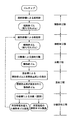
図1及び図2に示す本発明に係る微粉砕ゴムの製法は下記の5工程を備えているものである。
粗粉砕工程 :ゴムチップを粗粉砕機1で粗粉砕ゴムに加工する。
細粉砕工程 :上記粗粉砕ゴムを細粉砕機2によって細粉砕ゴムに加工する。
分離工程 :上記細粉砕ゴムの互いに連なっている細粉砕ゴムの粒体に対して分離機
3によって衝撃力を付与して強制的に分離して微粉砕ゴムにする。
混合工程 :混合機4により上記微粉砕ゴムに固着防止剤を添加しながら混合する。
分級回収工程:分級機5により固着防止剤が添加された上記微粉砕ゴムを所定の粒径を
有する微粉末ゴム製品とそれ以外のものに分級(選別)して回収する。
The method for producing finely pulverized rubber according to the present invention shown in FIGS. 1 and 2 includes the following five steps.
Coarse pulverization step: The rubber chips are processed into coarse pulverized rubber by the
Fine pulverization step: The coarse pulverized rubber is processed into fine pulverized rubber by the
Separation step: Separator for finely crushed rubber particles connected to each other.
The impact force is applied by 3 to forcibly separate into a finely crushed rubber.
Mixing step: Mixing is performed while adding an anti-sticking agent to the finely pulverized rubber by the mixer 4.
Classifying and collecting step: The finely pulverized rubber to which the anti-sticking agent has been added by the
Classify (select) and collect fine rubber product and other products.
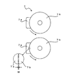
粗粉砕工程においては、図2に示すように例えば廃タイヤ(ビートワイヤなどタイヤ補強材除去処理済)を幾つかに切断したカットタイヤを所定の大きさに破砕したゴムチップ(タイヤチップ)をゴム原材料として粗粉砕機1のホッパー1aに供給塔6から投入し、粉砕室内に設けられている粗粉砕手段7(図3)によって粗粉砕ゴムに加工する。投入するゴムチップの粒径は例えば1mm〜8mm範囲内のものである。
粗粉砕ゴムは表面に孔を備え、縮れたような形態でかつ柔軟性を有するゴム(以下「粗ちぢれゴム」という。)である。
粗ちぢれゴムを効率良く製造可能とするために、図3に示す粗粉砕手段7は固定刃7aと粉砕ロール7bとを組み合わせたものを一段又は図上下方向に複数段(図では2段)配置して構成されている。
なお、固定刃7aと粉砕ロール7bとを組み合わせたものを複数組横方向に並べ、横方向に複数段配置したものであっても良い。
対向する固定刃7aと粉砕ロール7bとの間には隙間W(図3)があけられている。投入する上記ゴムチップの粒径をDとすると、隙間WはD/30〜35であることが好ましい。
一方の固定刃7aにおいて、図4及び図5に示すように粉砕ロール7bと対向する側には、内側(図4左側)に凹となる円弧面7a1を形成してあり、この円弧面には粉砕ロールの外周面が嵌め込まれている。固定刃7aの円弧面7a1には図5左右方向に伸びる複数の溝7a11が上下方向に間隔を置いて設けられている。
他方の粉砕ロール7bにおいて、図3及び図6に示すように粉砕ロールの外周面には粉砕刃7b1が設けられている。図6では、粉砕刃7b1の方向が粉砕ロール7bの中央部から左右両側でかつ斜め上方に向けて傾斜され、この中央部を中心として「V」字となっている。図7に示すように、粉砕刃7b1のピッチPは1.0mm〜1.5mmの範囲が望ましい。ピッチPの値が上記範囲外であると、期待する粗ちぢれゴムが製造できにくく、約1.0未満である場合には粗粉砕処理に時間がかかり、1.5mmを越えると次の細粉砕工程の段階で作業効率に悪影響を与える
。また隣接する粉砕刃7b1がなす角度θは85°〜95°の範囲が望ましい。角度θが上記範囲外であると、期待する粗ちぢれゴムの生産効率が低下し、角度θ<85°である場合には刃先の耐久性が低下し、角度θ>95°である場合には粗粉砕処理に時間がかかる。粉砕ロール7bの回転数は80rpm以上が望ましい。回転数が80rpmに達しない場合には、期待する粗ちぢれゴムの生産効率が低下するおそれがある。粉砕刃7b1の高さdはピッチP/2.5〜3.5であることが好ましい。
粗粉砕時に、固定状態にある固定刃7aに対して粉砕ロール7bを回転させながら粉砕作業を行うので、せん断力を主にして圧縮力や摩擦力の複合作用によって、ある程度の大きさの粗ちぢれゴムの製造が可能になり、また粉砕刃7b1の方向が粉砕ロール7bの中央部を中心として「V」字となっているため、粗ちぢれゴムが粉砕ロール7bの中央部に移動され、粗粉砕作業が能率的に行われる。
粗粉砕工程で処理された粗ちぢれゴムは、圧縮力や摩擦力の複合作用が粗粉砕の対象物であるゴム内の粒内を伝播し、ゴム粒内により小さな境界線を発生させて、小さい塊を形成しつつも粉砕状態にある。
粗粉砕工程では、粗ちぢれゴムのゴム粒体が結合されて凝集状態にあっても、一つの粒子(ゴム粒体)が粒径0.5mm以下に粉砕可能にするために、粉砕ロール7bの回転数、粉砕刃のP(ピッチ)、θ(角度)、d(高さ)、固定刃7aと粉砕ロール7bとの隙間Wなどの各条件を調整する。
なお、粉砕刃7b1の方向も必ずしも「V」字を形成するものでなくても良い。
粗粉砕手段7は対のロールを対向方向に回転させかつその回転数を異にする二軸のものを使用しても良い。この場合には対のロールの粉砕刃同士によるせん断力及び摩擦力の作用によってある程度の大きさの粗ちぢれゴムの製造が可能になる。
In the coarse pulverization step, as shown in FIG. 2, for example, rubber chips (tire chips) obtained by crushing a cut tire obtained by cutting a waste tire (having a tire reinforcing material such as a beat wire removed) into a predetermined size are used as rubber raw materials. As shown in FIG. 3, the pulverizer is fed into the hopper 1a of the
The coarsely pulverized rubber is a rubber having pores on the surface, in a crimped form and having flexibility (hereinafter, referred to as “coarse crumb rubber”).
In order to make it possible to efficiently produce rough curled rubber, the coarse crushing means 7 shown in FIG. 3 has a combination of a fixed blade 7a and a crushing roll 7b arranged in a single stage or a plurality of stages (two stages in the figure) in the vertical direction of the figure. Configured.
In addition, what combined the fixed blade 7a and the grinding | pulverization roll 7b may be arranged in the horizontal direction, and may be arranged in multiple steps in the horizontal direction.
A gap W (FIG. 3) is provided between the opposed fixed blade 7a and the grinding roll 7b. When the particle diameter of the rubber chip to be introduced is D, the gap W is preferably D / 30 to 35.
In one fixed blade 7a, as shown in FIGS. 4 and 5, an arc surface 7a1 which is concave on the inner side (left side in FIG. 4) is formed on the side facing the crushing roll 7b. The outer peripheral surface of the pulverizing roll is fitted. A plurality of grooves 7a11 extending in the left-right direction in FIG. 5 are provided on the circular arc surface 7a1 of the fixed blade 7a at intervals in the vertical direction.
In the other grinding roll 7b, as shown in FIGS. 3 and 6, a grinding blade 7b1 is provided on the outer peripheral surface of the grinding roll. In FIG. 6, the direction of the pulverizing blade 7b1 is inclined from the central part of the pulverizing roll 7b on both the left and right sides and obliquely upward, and has a “V” shape centering on this central part. As shown in FIG. 7, the pitch P of the pulverizing blades 7b1 is preferably in the range of 1.0 mm to 1.5 mm. If the value of the pitch P is out of the above range, it is difficult to produce the expected rough crumb rubber. If it is less than about 1.0, it takes time for the coarse pulverization process. It adversely affects work efficiency at the process stage. The angle θ formed by the adjacent crushing blade 7b1 is preferably in the range of 85 ° to 95 °. When the angle θ is out of the above range, the expected production efficiency of the rough rubber is lowered. When the angle θ <85 °, the durability of the cutting edge is lowered. When the angle θ> 95 °, Coarse pulverization takes time. As for the rotation speed of the grinding | pulverization roll 7b, 80 rpm or more is desirable. If the rotational speed does not reach 80 rpm, there is a risk that the production efficiency of the expected rough drown rubber will be reduced. The height d of the crushing blade 7b1 is preferably a pitch P / 2.5 to 3.5.
During coarse pulverization, the pulverization work is performed while rotating the pulverization roll 7b with respect to the fixed blade 7a in a fixed state. Rubber can be manufactured, and the direction of the grinding blade 7b1 is “V” centered on the center of the grinding roll 7b, so that the coarsely crushed rubber is moved to the center of the grinding roll 7b and coarsely crushed. Work is done efficiently.
Coarse rubber that has been processed in the coarse pulverization process is small in that the combined action of compressive force and frictional force propagates through the particles in the rubber that is the object of coarse pulverization, generating smaller boundaries in the rubber particles. It is in a pulverized state while forming a lump.
In the coarse pulverization step, even if the rubber particles of the coarsely crushed rubber are combined and in an agglomerated state, one particle (rubber particle) can be pulverized to a particle size of 0.5 mm or less. Various conditions such as the rotational speed, P (pitch), θ (angle), d (height) of the grinding blade, and the gap W between the fixed blade 7a and the grinding roll 7b are adjusted.
Note that the direction of the crushing blade 7b1 does not necessarily need to form a “V” shape.
The coarse crushing means 7 may be a biaxial one that rotates a pair of rolls in the opposite direction and has different rotation speeds. In this case, it becomes possible to produce a coarse rubber of a certain size by the action of the shearing force and frictional force between the grinding blades of the pair of rolls.
細粉砕工程は、上記粗ちぢれゴムを細粉砕機2によって細粉砕ゴムに加工する。
図2に示すように、粗粉砕機1で処理された粗粉砕ゴムはスクリューコンベア1b及びベルトコンベア8によって細粉砕機2まで搬送されて、この細粉砕機のホッパー2aに投入され、粉砕室内に設けられている細粉砕手段9(図8)よって細粉砕ゴムに加工される。
細粉砕ゴムは粗ちぢれゴムと比較してさらに表面に孔を備えた、より一層粒径が小さくて縮れ形態で極めて柔軟性のあるゴム(以下「細ちぢれゴム」という。)である。
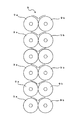
細粉砕手段9は、細ちぢれゴムを効率良く製造可能にするために、対の粉砕ロール9a,9bを組み合わせたものを図8に示すように上下方向に複数段(図では6段)配置して構成されている。
なお、対の粉砕ロール9a,9bを組み合わせたものを複数組横方向に並べ、横方に複数段配置したものであっても良い。
粉砕ロール9aと粉砕ロール9bとは互いに回転数が異なっている。そして粉砕ロール9a,9bによって、粗ちぢれゴムをさらに細かく粉砕して(粗ちぢれゴムの粒径を小さくしてその径の分布を狭くして)細ちぢれを製造可能とするためには、各粉砕ロールの表面を平滑面又は微細な凹凸面とすることが好ましい。粗ちぢれゴムから細ちぢれゴムへ転換製造する細粉砕工程では、対向する粉砕ロール9a,9b間の隙間をできるだけ狭く、例えば0.05mm以下に設定することによって粉砕ゴムが粉砕ロール間に導かれながら徐々に圧縮され、さらに粉砕ロール間の隙間に近づくにしたがって圧縮力が増大すると共に、粉砕ロールの回転比の異なる相対的速度差により、粉砕ゴムに対して圧縮力と摩擦力がかけられつつ、上記隙間において、最終的にはせん断力が加わり、その粉砕が実現される。
細ちぢれゴムの粉砕効率は粉砕ロール9a,9bの相対的な回転比率に大きく依存している。低速側の粉砕ロール9aと高速側の粉砕ロール9bとの回転比率は1:15〜30(1/30〜1/15)の範囲が望ましい。回転比率が上記範囲外であると、期待する細ちぢれゴムの生産効率が低下するおそれがある。回転比率が1:30すなわち1/30未満の場合には高速側の粉砕ロール9bの回転が低速側の粉砕ロール9aのそれと比較してかなり速くなるので粉砕ゴムの発熱により細ちぢれゴムの品質が低下するおそれがあり、1:15すなわち1/15を越えると、粉砕効率の低下を招くおそれがある。
また低速側及び高速側の各粉砕ロールの表面を微細な凹凸面(図9では、粉砕ロール19aの表面に所定の高さhを有する突起19a1を密に配した粗面)とした場合、細ちぢれゴムの粒径を小さくするために、凹凸面における突起19a1の高さhが0mmより大きく0.05mm以下に設定するのが良い。このように設定されることにより、細ちぢれゴムは結合されて凝縮状態にはあるが、一つのゴム粒径を0.15mm以下にすることが可能となり、実験例では得られた細ちぢれゴム全体の約90%がゴム粒径0.15mm以下のもので占められた。
細粉砕工程では、粗ちぢれゴムをさらに細かく粉砕するためには、上述したように粉砕ロール9a,9bの回転比率、粉砕ロールの表面(平滑面、微細な凹凸面、突起の高さh)及び粉砕回数(一段、複数段)などの各条件を調整する。
細粉砕工程で得られた細ちぢれゴムはゴム粒体が結合された塊(凝縮状態)を形成しているものの、一つのゴム粒子(ゴム粒体)の粒径が小さく、また表面は微細な凹凸面を有し、表面積が大きく、原料として使用する場合、他の原料との反応面が大きくなり、結果としてゴム強度が保たれる。
In the fine pulverization step, the coarsely crushed rubber is processed into fine pulverized rubber by the
As shown in FIG. 2, the coarsely pulverized rubber processed by the
The finely crushed rubber is a rubber having a pore size on the surface as compared with the coarsely crushed rubber and having a smaller particle size and being in a crimped form (hereinafter referred to as “finely crushed rubber”).
The fine pulverizing means 9 is a combination of a pair of pulverizing
A combination of a pair of crushing
The pulverizing roll 9a and the pulverizing
The grinding efficiency of the finely crushed rubber greatly depends on the relative rotation ratio of the grinding rolls 9a and 9b. The rotation ratio between the low-speed side pulverizing roll 9a and the high-speed
Further, when the surface of each pulverizing roll on the low speed side and the high speed side is a fine concavo-convex surface (in FIG. 9, a rough surface in which protrusions 19a1 having a predetermined height h are densely arranged on the surface of the pulverizing roll 19a), In order to reduce the particle size of the twisted rubber, the height h of the protrusion 19a1 on the uneven surface is preferably set to be greater than 0 mm and not greater than 0.05 mm. By setting in this way, the finely crushed rubber is combined and in a condensed state, but it becomes possible to make one rubber particle size 0.15 mm or less. About 90% of the rubber was occupied by rubber particles having a particle size of 0.15 mm or less.
In the fine pulverization step, in order to finely pulverize the coarse rubber, as described above, the rotation ratio of the pulverizing rolls 9a and 9b, the surface of the pulverizing roll (smooth surface, fine uneven surface, projection height h) and Adjust each condition such as the number of grinding (single stage, multiple stages).
The finely crushed rubber obtained in the fine pulverization process forms a lump (condensed state) in which rubber particles are combined, but the particle size of one rubber particle (rubber particle) is small and the surface is fine. When used as a raw material, it has an uneven surface, has a large surface area, and has a large reaction surface with other raw materials, and as a result, the rubber strength is maintained.
分離工程は、上記細ちぢれゴムの互いに連なっている細粉砕ゴムの粒体に対して分離機3によって衝撃力を付与して細粉砕ゴムの粒体を強制的に分離して微粉砕ゴムにする。
図2に示すように、細粉砕機2によって処理された細ちぢれゴムはスクリューコンベア2bによって分離機3まで搬送されて、この分離機の投入口部3aに投入され、分離室内に設けられているピン付き回転ディスクの回転によって細粉砕ゴムに加工される。ピン付き回転ディスクは駆動モータ3bの駆動力によって回転し、この回転に伴ってピンが分離室内を円周方向に回転移動し、移動するピンに投入された細ちぢれゴムが繰り返し衝突し、その衝撃力と、高速回転するピンによって生じる気流に乗った細ちぢれゴム同士の摩擦力とが分離に寄与する。ピン付き回転ディスクの周速度50m/s以上が好ましいが、この周速度の範囲はピン付き回転ディスクの大きさ及び容積率並びに求める粒径に応じて適宜設定する。
また分離機3への細ちぢれゴムの投入量は分離室の容積に対する充填率の大小によって分離効率が変化するが、実験例によれば充填率30%〜40%の範囲が最大効率を得るためには好ましい。この事実は、単に上記ピンへの細ちぢれゴムの衝突力のみではなく、細ちぢれゴム同士の衝突と摩擦により効率的に分離されるものと考えられる。
分離効率の低下を抑えるために、分離機3における分離室の室温(処理温度領域)が40°C〜160°Cであることが好ましい。160°Cを超えると、細ちぢれゴムの粘着性が増して分離効果を低下させ、40°Cより低温の場合にはゴムが硬化に伴い分離機に負荷をかけることとなり、生産効率の低下を招くおそれがある。
In the separation step, impact force is applied to the finely pulverized rubber particles connected to each other by the
As shown in FIG. 2, the finely crushed rubber processed by the
The amount of the finely crushed rubber into the
In order to suppress a decrease in separation efficiency, the room temperature (treatment temperature region) of the separation chamber in the
混合工程では、分離工程を経た微粉砕ゴムに固着防止剤を混合機4によって添加混合する。
図2に示すように、分離機3で処理された微粉砕ゴムは搬送ダクト3cによって混合機4のタンク4aまで圧送されて、このタンクの下部に設けられている混合室4b内に供給される。混合室4bには固着防止剤の供給タンク4cが接続されており、この供給タンク4cから固着防止剤が混合室内へ供給される。混合室4b内へ供給された微粉砕ゴムと固着防止剤とは混合室内に設けられている撹拌スクリューなどからなる混合手段4dによって攪拌され混合される。
固着防止剤としては、充填材(炭酸カルシウム、アルミナなど)や補強材(カーボンブラック、タルク、シリカなど)が適当である。
固着防止剤として炭酸カルシウムを選択した場合には、その添加量は細ちぢれゴムの7%〜15%が良い。7%未満の場合には固着防止機能が低下し、15%を越えると製品化した場合の利用の分野が制限される。
微粉砕ゴムに固着防止剤を添加することによって微粉砕ゴムの表面がコーティングされ、微粉砕ゴムが再び付着結合することを防止することができると共に、ゴムの用途によっては所定の粒径が要求される場合には、簡易な分級機によって要求される粒径を分級(選別)することができる利点がある。この種の利点を確保しながらも、固着防止剤の添加量が少ないことがコストダウンに寄与し、タイヤの原料として再利用するのに好都合である。このため、混合手段4dよって混合する速度は、一度コーティングされたものが微粉砕ゴムの表面から剥離しない程度に、また表面の微細な孔に入り込み固着防止機能が不能とならない程度に低速域であることが好ましい。
In the mixing step, an anti-sticking agent is added and mixed by the mixer 4 to the finely pulverized rubber that has undergone the separation step.
As shown in FIG. 2, the finely pulverized rubber processed by the
As the anti-sticking agent, fillers (calcium carbonate, alumina, etc.) and reinforcing materials (carbon black, talc, silica, etc.) are suitable.
When calcium carbonate is selected as the anti-sticking agent, the amount added is preferably 7% to 15% of the finely crushed rubber. If it is less than 7%, the anti-sticking function is lowered, and if it exceeds 15%, the field of use when it is commercialized is limited.
By adding an anti-sticking agent to the finely pulverized rubber, the surface of the finely pulverized rubber can be coated to prevent the finely pulverized rubber from adhering and bonding again, and a predetermined particle size is required depending on the use of the rubber. In this case, there is an advantage that the required particle size can be classified (selected) by a simple classifier. While securing this kind of advantage, a small addition amount of the anti-sticking agent contributes to cost reduction and is advantageous for reuse as a tire raw material. For this reason, the mixing speed by the mixing means 4d is a low speed range so that once coated, it does not peel from the surface of the finely pulverized rubber, and does not enter the fine holes on the surface and disable the sticking prevention function. It is preferable.
分級回収工程は、混合工程における固着防止剤が添加された微粉砕ゴムを分級機5によって分級して回収する工程である。
分級回収工程において、混合機4で固着防止剤が添加された上記微粉砕ゴムは搬送ダクト4eによって分級機5の一次貯蔵タンク5aに貯蔵され、そしてこの一次貯蔵タンク5aから二次貯蔵タンク5bに貯蔵される。二次貯蔵タンク5bに貯蔵された上記微粉砕ゴムは徐々に下部出口から篩5cに落下して、この篩によって所定の粒径の微粉砕ゴムと、とそれ以外すなわち所定粒径を超えた微粉砕ゴムとに選別され、所定粒径の微粉砕ゴムは微粉末ゴム製品として回収タンク5dに回収され、所定粒径を超えた微粉砕ゴムは微粉末ゴム製品として回収タンク5dとは別の回収タンクに回収され、必要に応じて細粉砕機2に戻して所定粒径を有する微粉砕ゴムを得るための処理を行う。
所定粒径を有する微粉砕ゴムとしては、例えば粒径0.15mm(♯100)以下のものであり、それ以外の微粉砕ゴムは粒径0.15mm(♯100)を超えるものである。
The classifying and collecting step is a step of classifying and collecting the finely pulverized rubber added with the anti-sticking agent in the mixing step with the
In the classifying and collecting step, the finely pulverized rubber added with the anti-sticking agent in the mixer 4 is stored in the primary storage tank 5a of the
The finely pulverized rubber having a predetermined particle size is, for example, one having a particle size of 0.15 mm (# 100) or less, and other finely pulverized rubbers having a particle size exceeding 0.15 mm (# 100).
第1実施例について説明する。
3mmゴムチップを二段に配置した固定刃及び粉砕ロールを備えた粗粉砕機1を用いて、しかも固定刃7a及び粉砕ロール7bの隙間Wを3/31、粉砕ロールの回転数を82rm、P=1.20に設定して、その粉砕室によって粗ちぢれゴムに加工した。
6段に配置した低速側粉砕ロール9a及び高速側粉砕ロール9bを備えた細粉砕機2を用いて、しかも高低各側の粉砕ロールの回転比率を1:15に設定して粗ちぢれゴムを細ちぢれに加工した。
分離機の分離室内への細ちぢれゴムの充填率を35%に設定し、ピン付き回転ディスクの周速度60m/sとして、分離加工して微粉砕ゴムを得た。微粉砕ゴムには、粒径0.15mm(♯100)以下のものが約90%、残りが粒径0.15mmを超えるものであった。
混合機4の混合室に固着防止剤として炭酸カルシウム8%を細ちぢれゴムに添加して混合し、その後分級した。粒径0.15mm(♯100)以下の微粉砕ゴムを製品として回収し、上記粒径を超えた微粉砕ゴムを細粉砕機2に戻した。
A first embodiment will be described.
Using a
Using a
A finely crushed rubber was obtained by performing separation processing at a peripheral speed of a rotating disk with a pin of 60 m / s, setting the filling rate of finely crushed rubber into the separation chamber of the separator to 35%. Of the finely pulverized rubber, those having a particle size of 0.15 mm (# 100) or less were about 90%, and the remainder were those exceeding 0.15 mm.
In the mixing chamber of the mixer 4, 8% calcium carbonate as an anti-sticking agent was added to the finely crushed rubber and mixed, and then classified. The finely pulverized rubber having a particle size of 0.15 mm (# 100) or less was recovered as a product, and the finely pulverized rubber exceeding the particle size was returned to the
上述した本発明の微粉砕ゴムの製法では、粗粉砕工程では、粗粉砕手段7によりゴムチップの表面に摩擦力や圧縮力を加えながらせん断により粉砕するためにゴムチップの表面に孔が形成され、ちぢれた形態を有するものに加工され、その上細粉砕工程では、細粉砕手段9により粗ちぢれゴムの表面に摩擦力や圧縮力を加えながら粉砕するために、粗粉砕工程と比較してより一層その表面に凹凸が形成され、ちぢれた形態を有する細ちぢれゴムに加工され、分離工程では細ちぢれゴムに対して衝撃力が加えられるので結合状態にある粒体が強制的に分離され粒径0.15mm(♯100)より小さい微粉砕ゴムを量産することができる。
粗粉砕手段7及び細粉砕手段9の加工条件を調整して、微粉砕領域である0.15mm(♯100)〜0.075mm(♯200)又はその範囲の粒径以下の微粉末ゴムを機械的粉砕で量産を可能とするものである。
分離工程では、細ちぢれゴムのうちゴム粒体が連なった凝集状態にある細ちぢれゴムに対して強制的に分散させるものであるが、分離後の細ちぢれゴムを混合工程を経ることなく分級回収工程に移行させて、例えば風力利用の分級機によって所定粒径の微粉末ゴムとそれ以外のものとに選別するものであってもよく、必ずしも固着防止剤を添加する混合工程を要しない。
In the method for producing finely pulverized rubber of the present invention described above, in the coarse pulverization step, pores are formed on the surface of the rubber chip so that the coarse pulverization means 7 pulverizes by shearing while applying frictional force or compression force to the surface of the rubber chip. In addition, in the fine pulverization step, the surface of the coarsely crushed rubber is pulverized while applying a frictional force or a compressive force by the fine pulverization means 9, so that the pulverization step is further compared with the coarse pulverization step. Concavities and convexities are formed on the surface and processed into a finely crushed rubber, and in the separation step, an impact force is applied to the finely crushed rubber, so that the particles in the bound state are forcibly separated and a particle size of 0. Finely pulverized rubber smaller than 15 mm (# 100) can be mass-produced.
By adjusting the processing conditions of the coarse pulverization means 7 and fine pulverization means 9, fine powder rubber having a fine pulverization region of 0.15 mm (# 100) to 0.075 mm (# 200) or a particle size within the range is machined. It can be mass-produced by mechanical grinding.
In the separation process, the finely crushed rubber is forcibly dispersed into the finely crushed rubber that is in an agglomerated state where the rubber particles are continuous, but the separated finely crushed rubber is classified and collected without going through the mixing process. The process may be shifted to a fine powder rubber having a predetermined particle size and other types by using a classifier using wind power, for example, and a mixing process for adding an anti-sticking agent is not necessarily required.
1 粗粉砕機
2 細粉砕機
3 分離機
4 混合機
5 分級機
7 粗粉砕手段
7a 固定刃
7a1 円弧面
7a11 溝
7b 粉砕ロール
7b1 粉砕刃
9 細粉砕手段
9a,9b 粉砕ロール
19a 粉砕ロール
19a1 突起
P 粗粉砕ロールの粉砕刃のピッチ
W 対向する固定刃と粗粉砕ロールとの隙間
d 粗粉砕ロールの粉砕刃の高さ
h 突起の高さ
θ 隣接する粉砕刃がなす角度
DESCRIPTION OF
Claims (10)
上記粗粉砕ゴムを細粉砕ロールによって細粉砕ゴムに加工する細粉砕工程と、
上記細粉砕ゴム中に含まれかつ互いに連なっているゴム粒体に対して分離機によって衝撃力を付与して強制的に分離して微粉砕ゴムにする分離工程と
を具備していることを特徴とする微粉砕ゴムの製法。 A coarse pulverization step of processing the crushed rubber raw material into coarse pulverized rubber by means of coarse pulverization;
A fine pulverization step of processing the coarsely pulverized rubber into fine pulverized rubber by a fine pulverization roll;
Separating the rubber particles contained in the finely pulverized rubber and connected to each other by applying an impact force with a separator to forcibly separate them into a finely pulverized rubber. A method for producing finely crushed rubber.
Priority Applications (1)
| Application Number | Priority Date | Filing Date | Title |
|---|---|---|---|
| JP2004368810A JP4579671B2 (en) | 2004-12-21 | 2004-12-21 | Production method of finely crushed rubber |
Applications Claiming Priority (1)
| Application Number | Priority Date | Filing Date | Title |
|---|---|---|---|
| JP2004368810A JP4579671B2 (en) | 2004-12-21 | 2004-12-21 | Production method of finely crushed rubber |
Publications (2)
| Publication Number | Publication Date |
|---|---|
| JP2006176558A true JP2006176558A (en) | 2006-07-06 |
| JP4579671B2 JP4579671B2 (en) | 2010-11-10 |
Family
ID=36730963
Family Applications (1)
| Application Number | Title | Priority Date | Filing Date |
|---|---|---|---|
| JP2004368810A Active JP4579671B2 (en) | 2004-12-21 | 2004-12-21 | Production method of finely crushed rubber |
Country Status (1)
| Country | Link |
|---|---|
| JP (1) | JP4579671B2 (en) |
Cited By (4)
| Publication number | Priority date | Publication date | Assignee | Title |
|---|---|---|---|---|
| JP2009195869A (en) * | 2008-02-25 | 2009-09-03 | Kotobuki Sangyo Kk | Agitating and mixing system |
| JP2010260208A (en) * | 2009-04-30 | 2010-11-18 | Bridgestone Corp | Method and apparatus for manufacturing finely crushed rubber and rubber composition |
| JP2015535019A (en) * | 2012-11-02 | 2015-12-07 | リーハイ テクノロジーズ, インコーポレイテッド | Regenerated elastomer material and method for functionalizing a composition comprising the same |
| CN115122542A (en) * | 2022-06-28 | 2022-09-30 | 安徽中宏橡塑有限公司 | Rubber powder fine crushing device for rubber production |
Citations (5)
| Publication number | Priority date | Publication date | Assignee | Title |
|---|---|---|---|---|
| JPS5390381A (en) * | 1977-01-18 | 1978-08-09 | Usm Corp | Method for processing rubber tire |
| JPH02128804A (en) * | 1988-10-13 | 1990-05-17 | Harold Perkel | Low-temperature crushing method and device for waste tire |
| JPH0576793A (en) * | 1991-09-18 | 1993-03-30 | Ube Ind Ltd | Pulverizing equipment |
| JP2006006991A (en) * | 2004-06-22 | 2006-01-12 | Yoshiaki Nitta | Rubber chip fine crushing treatment method and apparatus |
| JP2006075711A (en) * | 2004-09-09 | 2006-03-23 | Bridgestone Corp | Rubber composition and pneumatic tire |
-
2004
- 2004-12-21 JP JP2004368810A patent/JP4579671B2/en active Active
Patent Citations (5)
| Publication number | Priority date | Publication date | Assignee | Title |
|---|---|---|---|---|
| JPS5390381A (en) * | 1977-01-18 | 1978-08-09 | Usm Corp | Method for processing rubber tire |
| JPH02128804A (en) * | 1988-10-13 | 1990-05-17 | Harold Perkel | Low-temperature crushing method and device for waste tire |
| JPH0576793A (en) * | 1991-09-18 | 1993-03-30 | Ube Ind Ltd | Pulverizing equipment |
| JP2006006991A (en) * | 2004-06-22 | 2006-01-12 | Yoshiaki Nitta | Rubber chip fine crushing treatment method and apparatus |
| JP2006075711A (en) * | 2004-09-09 | 2006-03-23 | Bridgestone Corp | Rubber composition and pneumatic tire |
Cited By (6)
| Publication number | Priority date | Publication date | Assignee | Title |
|---|---|---|---|---|
| JP2009195869A (en) * | 2008-02-25 | 2009-09-03 | Kotobuki Sangyo Kk | Agitating and mixing system |
| JP2010260208A (en) * | 2009-04-30 | 2010-11-18 | Bridgestone Corp | Method and apparatus for manufacturing finely crushed rubber and rubber composition |
| JP2015535019A (en) * | 2012-11-02 | 2015-12-07 | リーハイ テクノロジーズ, インコーポレイテッド | Regenerated elastomer material and method for functionalizing a composition comprising the same |
| EP2914635B1 (en) * | 2012-11-02 | 2020-06-24 | Lehigh Technologies, Inc. | Methods of functionalizing reclaimed elastomer material and compositions comprising the same |
| CN115122542A (en) * | 2022-06-28 | 2022-09-30 | 安徽中宏橡塑有限公司 | Rubber powder fine crushing device for rubber production |
| CN115122542B (en) * | 2022-06-28 | 2024-03-15 | 安徽中宏橡塑有限公司 | Rubber is finely divided device for rubber production |
Also Published As
| Publication number | Publication date |
|---|---|
| JP4579671B2 (en) | 2010-11-10 |
Similar Documents
| Publication | Publication Date | Title |
|---|---|---|
| KR101045634B1 (en) | The production equipment of powder material from the waste rubber | |
| JP3626098B2 (en) | Beads for grinding, bead manufacturing method and manufacturing apparatus | |
| JP2006507928A (en) | Fine grinding method for vulcanized rubber materials | |
| US8157194B2 (en) | Method for separating unvulcanized rubberized steel cord material for tires | |
| CN102416675B (en) | Industrializable waste thermosetting plastic regeneration process and equipment based on mechanical and physical method | |
| JP2014530133A (en) | Plastic material processing equipment | |
| JP4904389B2 (en) | Method for producing fine paper powder and method for producing resin composition containing fine paper powder | |
| JP4902970B2 (en) | Rubber composition and pneumatic tire using the same | |
| KR20220033464A (en) | A method for crushing plastic waste, and a method for manufacturing a synthetic resin molded product using plastic waste | |
| JP2007126518A (en) | Reclaimed rubber-containing rubber composition and pneumatic tire | |
| JP4579671B2 (en) | Production method of finely crushed rubber | |
| KR20100101201A (en) | The production equipment of powder material from the waste rubber or the waste thermoplastic | |
| JP2006348179A (en) | Rubber composition and pneumatic tire | |
| CN202271460U (en) | Industrialized waste and old thermosetting plastic regeneration equipment based on mechanical and physical method | |
| JP5513435B2 (en) | Manufacturing method of secondary materials for steel | |
| EP1302291A1 (en) | Grinding device for resin composition | |
| KR100663945B1 (en) | Fine powder of waste polyurethane foam and method for manufacturing thereof | |
| JP2945809B2 (en) | Apparatus for peeling coating film from plastic material or pulverizing / granulating powder material containing plastic material | |
| JP4565989B2 (en) | Production method of finely crushed rubber | |
| JP2010260208A (en) | Method and apparatus for manufacturing finely crushed rubber and rubber composition | |
| JP4287732B2 (en) | Powder and granulator | |
| JPH10338518A (en) | Production of calcium carbonate | |
| JP3085676U (en) | Wood-like molded products and wood-like molded product manufacturing equipment | |
| JP2001334168A (en) | Method for recovering fiber material | |
| JP2003112313A (en) | Method and equipment for manufacturing resin mixed wood powder and method and equipment for manufacturing woody molded article |
Legal Events
| Date | Code | Title | Description |
|---|---|---|---|
| A521 | Request for written amendment filed |
Free format text: JAPANESE INTERMEDIATE CODE: A523 Effective date: 20060411 |
|
| A621 | Written request for application examination |
Free format text: JAPANESE INTERMEDIATE CODE: A621 Effective date: 20071130 |
|
| A711 | Notification of change in applicant |
Free format text: JAPANESE INTERMEDIATE CODE: A712 Effective date: 20080218 |
|
| A521 | Request for written amendment filed |
Free format text: JAPANESE INTERMEDIATE CODE: A821 Effective date: 20080218 |
|
| A977 | Report on retrieval |
Free format text: JAPANESE INTERMEDIATE CODE: A971007 Effective date: 20100716 |
|
| TRDD | Decision of grant or rejection written | ||
| A01 | Written decision to grant a patent or to grant a registration (utility model) |
Free format text: JAPANESE INTERMEDIATE CODE: A01 Effective date: 20100817 |
|
| A01 | Written decision to grant a patent or to grant a registration (utility model) |
Free format text: JAPANESE INTERMEDIATE CODE: A01 |
|
| A61 | First payment of annual fees (during grant procedure) |
Free format text: JAPANESE INTERMEDIATE CODE: A61 Effective date: 20100826 |
|
| FPAY | Renewal fee payment (event date is renewal date of database) |
Free format text: PAYMENT UNTIL: 20130903 Year of fee payment: 3 |
|
| R150 | Certificate of patent or registration of utility model |
Ref document number: 4579671 Country of ref document: JP Free format text: JAPANESE INTERMEDIATE CODE: R150 Free format text: JAPANESE INTERMEDIATE CODE: R150 |
|
| R250 | Receipt of annual fees |
Free format text: JAPANESE INTERMEDIATE CODE: R250 |
|
| R250 | Receipt of annual fees |
Free format text: JAPANESE INTERMEDIATE CODE: R250 |
|
| R250 | Receipt of annual fees |
Free format text: JAPANESE INTERMEDIATE CODE: R250 |
|
| S531 | Written request for registration of change of domicile |
Free format text: JAPANESE INTERMEDIATE CODE: R313531 |
|
| R350 | Written notification of registration of transfer |
Free format text: JAPANESE INTERMEDIATE CODE: R350 |
|
| R250 | Receipt of annual fees |
Free format text: JAPANESE INTERMEDIATE CODE: R250 |
|
| S111 | Request for change of ownership or part of ownership |
Free format text: JAPANESE INTERMEDIATE CODE: R313117 |
|
| S531 | Written request for registration of change of domicile |
Free format text: JAPANESE INTERMEDIATE CODE: R313531 |
|
| R350 | Written notification of registration of transfer |
Free format text: JAPANESE INTERMEDIATE CODE: R350 |
|
| R250 | Receipt of annual fees |
Free format text: JAPANESE INTERMEDIATE CODE: R250 |
|
| R250 | Receipt of annual fees |
Free format text: JAPANESE INTERMEDIATE CODE: R250 |
|
| R250 | Receipt of annual fees |
Free format text: JAPANESE INTERMEDIATE CODE: R250 |
|
| R250 | Receipt of annual fees |
Free format text: JAPANESE INTERMEDIATE CODE: R250 |
|
| R250 | Receipt of annual fees |
Free format text: JAPANESE INTERMEDIATE CODE: R250 |
|
| R250 | Receipt of annual fees |
Free format text: JAPANESE INTERMEDIATE CODE: R250 |
|
| R250 | Receipt of annual fees |
Free format text: JAPANESE INTERMEDIATE CODE: R250 |
|
| R250 | Receipt of annual fees |
Free format text: JAPANESE INTERMEDIATE CODE: R250 |