JP2006167461A - Interchangeable tissue macerating and sculpting methods and devices - Google Patents
Interchangeable tissue macerating and sculpting methods and devices Download PDFInfo
- Publication number
- JP2006167461A JP2006167461A JP2005358072A JP2005358072A JP2006167461A JP 2006167461 A JP2006167461 A JP 2006167461A JP 2005358072 A JP2005358072 A JP 2005358072A JP 2005358072 A JP2005358072 A JP 2005358072A JP 2006167461 A JP2006167461 A JP 2006167461A
- Authority
- JP
- Japan
- Prior art keywords
- fluid jet
- suction
- tube
- cutting instrument
- tissue
- Prior art date
- Legal status (The legal status is an assumption and is not a legal conclusion. Google has not performed a legal analysis and makes no representation as to the accuracy of the status listed.)
- Abandoned
Links
Images


Classifications
-
- A—HUMAN NECESSITIES
- A61—MEDICAL OR VETERINARY SCIENCE; HYGIENE
- A61B—DIAGNOSIS; SURGERY; IDENTIFICATION
- A61B17/00—Surgical instruments, devices or methods, e.g. tourniquets
- A61B17/32—Surgical cutting instruments
- A61B17/3203—Fluid jet cutting instruments
-
- A—HUMAN NECESSITIES
- A61—MEDICAL OR VETERINARY SCIENCE; HYGIENE
- A61B—DIAGNOSIS; SURGERY; IDENTIFICATION
- A61B17/00—Surgical instruments, devices or methods, e.g. tourniquets
- A61B17/32—Surgical cutting instruments
- A61B17/3203—Fluid jet cutting instruments
- A61B17/32037—Fluid jet cutting instruments for removing obstructions from inner organs or blood vessels, e.g. for atherectomy
Landscapes
- Health & Medical Sciences (AREA)
- Surgery (AREA)
- Life Sciences & Earth Sciences (AREA)
- Biomedical Technology (AREA)
- Nuclear Medicine, Radiotherapy & Molecular Imaging (AREA)
- Engineering & Computer Science (AREA)
- Heart & Thoracic Surgery (AREA)
- Medical Informatics (AREA)
- Molecular Biology (AREA)
- Animal Behavior & Ethology (AREA)
- General Health & Medical Sciences (AREA)
- Public Health (AREA)
- Veterinary Medicine (AREA)
- Vascular Medicine (AREA)
- Surgical Instruments (AREA)
Abstract
Description
〔発明の分野〕
本願は、組織を浸軟して彫刻する高圧流体ジェットに関する。
(Field of the Invention)
The present application relates to a high pressure fluid jet that macerates and engraves tissue.
〔発明の背景〕
組織を切断したり剥離させたりする高圧流体ジェットシステムが、当該技術分野において知られている。流体ジェットカッタは、加圧流体を集中させて所望の組織に衝撃を与え、それにより組織を浸軟する。すると、組織を手術部位から吸引し又はこれとは違ったやり方で取り出すことができる。多くの器械は、流体ジェットノズルから距離を置いて位置決めされていて、流体ジェットと取り出された組織の両方を捕集する捕集管を有する閉ループ系を利用している。
BACKGROUND OF THE INVENTION
High pressure fluid jet systems that cut and detach tissue are known in the art. The fluid jet cutter concentrates the pressurized fluid and impacts the desired tissue, thereby macerating the tissue. The tissue can then be aspirated from the surgical site or removed in a different manner. Many instruments utilize closed loop systems that are positioned at a distance from the fluid jet nozzle and have a collection tube that collects both the fluid jet and the removed tissue.
公知の高圧流体ジェットシステムは有効であるが、これらシステムは一般に、塊状組織を除去する際の使用に限定されている。特に、現在の高圧流体ジェットに関し、流体送出管を捕集管に対して位置決めすることによっては、流体ジェットの経路内の2本の管相互間に位置決め可能な組織を除去できるに過ぎない。流体捕集管は、ユーザが流体ジェットを凹状であり、平らであり、又はそれどころか僅かに凸状である組織の方へ差し向けるのを阻止する。かくして、組織の高精度彫刻および侵食は、達成が困難である。 While known high pressure fluid jet systems are effective, these systems are generally limited to use in removing massive tissue. In particular, with current high pressure fluid jets, positioning the fluid delivery tube relative to the collection tube can only remove tissue that can be positioned between two tubes in the fluid jet path. The fluid collection tube prevents the user from directing the fluid jet toward tissue that is concave, flat, or even slightly convex. Thus, high precision engraving and erosion of tissue is difficult to achieve.
したがって、当該技術分野においては、組織の塊状除去および高精度彫刻の際に用いられる改良型高圧流体ジェットが要望されている。 Accordingly, there is a need in the art for an improved high pressure fluid jet for use in tissue mass removal and high precision engraving.
〔発明の概要〕
組織の選択的な塊状除去と高精度彫刻のための種々の流体ジェット切断器械が提供される。例示の一実施形態では、流体ジェット切断器械が提供され、この流体ジェット切断器械は、流体ジェットを形成するノズルを備えた流体送出管(fluid delivery tube)と、流体送出管に選択的かつ取外し可能に嵌合できる複数本の吸出管(evacuation tube)とを有するのがよい。各吸出管は、ノズルにより形成された流体ジェットを捕集するようにノズルに対向すると共にこれから間隔を置いて位置決めされるようになった吸出ポートを有するのがよく、各吸出管の吸出ポートは、吸出ポートの開口部を横切って測定した断面積が、互いに異なっているのがよい。
[Summary of the Invention]
Various fluid jet cutting instruments are provided for selective mass removal of tissue and high precision engraving. In one exemplary embodiment, a fluid jet cutting instrument is provided, the fluid jet cutting instrument being a fluid delivery tube with a nozzle forming a fluid jet and selectively removable from the fluid delivery tube. It is preferable to have a plurality of evacuation tubes that can be fitted to the tube. Each suction pipe may have a suction port that faces and is spaced from the nozzle so as to collect the fluid jet formed by the nozzle, and the suction port of each suction pipe is The cross-sectional areas measured across the opening of the suction port should be different from each other.
例示の一実施形態では、流体ジェット切断器械は、第1の吸出ポートを備えた第1の吸出管および第2の吸出ポートを備えた第2の吸出管を含むのがよく、第1の吸出ポートの断面積は、第2の吸出ポートの断面積よりも大きいのがよい。例示の別の実施形態では、第1の吸出管の吸出ポートは、ノズルにより形成される流体ジェットの最大直径よりも実質的に大きい直径を有するのがよく、第2の吸出管の吸出ポートは、ノズルにより形成される流体ジェットの最大直径とほぼ同じである直径を有するのがよい。 In one exemplary embodiment, the fluid jet cutting instrument may include a first suction tube with a first suction port and a second suction tube with a second suction port, wherein the first suction tube The cross-sectional area of the port should be larger than the cross-sectional area of the second suction port. In another exemplary embodiment, the suction port of the first suction tube may have a diameter that is substantially greater than the maximum diameter of the fluid jet formed by the nozzle, and the suction port of the second suction tube is It may have a diameter that is approximately the same as the maximum diameter of the fluid jet formed by the nozzle.
例示の別の実施形態では、流体を形成するノズルを備えた流体送出管と、流体送出管に選択的かつ取外し可能に嵌合可能な第1および第2の吸出管とを有する外科用流体ジェット切断器械が提供される。各吸出管は、ノズルにより形成される流体ジェットを受け入れるようにノズルと対向して位置決めされるようになったジェット受入れ開口部を有するのがよい。一実施形態では、第1の吸出管は、組織の塊状除去を可能にするようになっているのがよく、第2の吸出管は、組織の高精度彫刻を可能にするようになっているのがよい。特に、例示の一実施形態では、第1の吸出管の流体ジェット受入れ開口部の断面積は、第1の吸出管の流体ジェット受入れ開口部のところで測定してノズルにより形成される流体ジェットの断面積よりも実質的に大きいのがよく、第2の吸出管の流体ジェット受入れ開口部の断面積は、第2の吸出管の流体ジェット受入れ開口部のところで測定して流体ジェットの断面積とほぼ同じであるのがよい。 In another exemplary embodiment, a surgical fluid jet having a fluid delivery tube with a fluid forming nozzle and first and second suction tubes that are selectively and removably matable to the fluid delivery tube. A cutting instrument is provided. Each suction tube may have a jet receiving opening adapted to be positioned opposite the nozzle to receive a fluid jet formed by the nozzle. In one embodiment, the first suction tube may be adapted to allow for removal of a mass of tissue, and the second suction tube may be adapted to allow for high precision engraving of tissue. It is good. In particular, in one exemplary embodiment, the cross-sectional area of the fluid jet receiving opening of the first suction tube is measured at the fluid jet receiving opening of the first suction tube and the breakage of the fluid jet formed by the nozzle. The cross-sectional area of the fluid jet receiving opening of the second suction pipe may be substantially larger than the area, and the cross-sectional area of the fluid jet receiving opening of the second suction pipe is approximately It should be the same.
例示の別の実施形態では、外科用流体ジェット切断器械が提供され、この外科用流体ジェット切断器械は、流体送出管および吸出管の周りに摺動自在に設けられたシースを有するのがよい。シースは、吸出管を取り外して交換できるようになっているのがよい。 In another exemplary embodiment, a surgical fluid jet cutting instrument is provided, which may have a sheath slidably disposed about a fluid delivery tube and a suction tube. The sheath may be adapted to be replaced by removing the suction tube.
本発明は又、組織の選択的な塊状除去と高精度彫刻のための方法を提供する。例示の一実施形態では、組織を除去するには、高圧流体ジェットを組織表面に隣接して位置決めして組織を塊状で除去するのがよい。高圧流体ジェットおよび組織を第1の吸出管に形成された第1の吸出ポート内に捕集するのがよい。例示の実施形態では、第1の吸出ポートは、第1の吸出ポートを開口部を横切って測定して断面積が高圧流体ジェットの断面積よりも実質的に大きい。次に、第1の吸出管に代えて第2の排気ポートを備えた第2の吸出管を用いるのがよく、第2の吸出ポートは、第2の吸出ポートの開口部を横切って測定して断面積が高圧流体ジェットの断面積とほぼ同じである。次に、高圧流体ジェットを組織表面に隣接して位置決めして組織を正確に彫刻するのがよい。高圧流体ジェットおよび組織を第2の吸出管の第2の吸出ポート内に捕集するのがよい。例示の実施形態では、高圧流体ジェットは、流体送出管に設けられたノズルにより形成され、第1および第2の吸出管は、流体送出管に選択的かつ取外し可能に嵌合できる。 The present invention also provides a method for selective bulk removal of tissue and high precision engraving. In one exemplary embodiment, to remove tissue, a high pressure fluid jet may be positioned adjacent to the tissue surface to remove the tissue in bulk. The high pressure fluid jet and tissue may be collected in a first suction port formed in the first suction tube. In the illustrated embodiment, the first suction port has a cross-sectional area that is substantially greater than the cross-sectional area of the high pressure fluid jet as measured by the first suction port across the opening. Next, it is preferable to use a second suction pipe having a second exhaust port instead of the first suction pipe, and the second suction port is measured across the opening of the second suction port. The cross-sectional area is almost the same as that of the high-pressure fluid jet. The high pressure fluid jet may then be positioned adjacent to the tissue surface to accurately engrave the tissue. The high pressure fluid jet and tissue may be collected in a second suction port of the second suction tube. In the illustrated embodiment, the high pressure fluid jet is formed by a nozzle provided in the fluid delivery tube, and the first and second suction tubes can be selectively and removably fitted to the fluid delivery tube.
さらに別の実施形態では、組織を除去する方法が提供され、この方法は、第1の吸出管を流体送出管に結合して、第1の吸出管に形成された第1の吸出ポートを流体送出管に設けられたノズルに対向して位置決めする段階を有する。第1の吸出管は、組織の塊状除去を可能にするようになっているのがよい。次に、ノズルにより形成される流体ジェットを用いて組織を塊状で除去するのがよく、流体ジェットおよび組織を第1の吸出管の第1の吸出ポート内に捕集するのがよい。次に、第1の吸出管に代えて第2の吸出管を用いて第2の吸出管に形成された第2の吸出ポートを流体送出管のノズルに対向して位置決めする。第2の吸出管は、組織の高精度彫刻を可能にするようになっているのがよい。ノズルにより形成される流体ジェットを用いて組織表面を高精度彫刻し、流体ジェットおよび組織を第2の吸出管の第2の吸出ポート内に捕集するのがよい。一実施形態では、第1の吸出ポートは、第1の吸出ポートの開口部を横切って測定して断面積が流体ジェットの断面積よりも実質的に大きいのがよく、第2の吸出ポートは、第2の吸出ポートの開口部を横切って測定して断面積が流体ジェットの断面積とほぼ同じであるのがよい。他の例示の実施形態では、第1の吸出管に代えて第2の吸出管を用いる段階は、第1の吸出管の周りに設けられたシースを摺動自在に取り外す段階と、第1の吸出管を取り外す段階と、第2の吸出管を流体送出管に対して位置決めする段階と、シースを第2の吸出管および流体送出管上でこれに沿って摺動させる段階とを含むのがよい。 In yet another embodiment, a method for removing tissue is provided, the method coupling a first suction tube to a fluid delivery tube and fluidizing a first suction port formed in the first suction tube. Positioning the nozzle opposite to the nozzle provided in the delivery pipe. The first suction tube may be adapted to allow removal of the tissue mass. The tissue can then be removed in bulk using a fluid jet formed by the nozzle, and the fluid jet and tissue can be collected in the first suction port of the first suction tube. Next, instead of the first suction pipe, a second suction pipe is used to position the second suction port formed in the second suction pipe so as to face the nozzle of the fluid delivery pipe. The second suction tube may be adapted to allow high precision engraving of tissue. The fluid jet formed by the nozzle may be used to precisely sculpt the tissue surface and collect the fluid jet and tissue in the second suction port of the second suction tube. In one embodiment, the first suction port may have a cross-sectional area that is substantially greater than the cross-sectional area of the fluid jet as measured across the opening of the first suction port, and the second suction port is The cross-sectional area, measured across the opening of the second suction port, should be approximately the same as the cross-sectional area of the fluid jet. In another exemplary embodiment, using the second suction pipe instead of the first suction pipe includes slidably removing a sheath provided around the first suction pipe, Removing the suction tube, positioning the second suction tube relative to the fluid delivery tube, and sliding the sheath over the second suction tube and the fluid delivery tube. Good.
〔発明の詳細な説明〕
組織の選択的な塊状除去と高精度彫刻のための種々の流体ジェット切断器械が提供される。例示の一実施形態では、この器械は、高圧流体ジェットを形成するノズルを備えた流体送出管と、流体送出管に選択的にかつ取外し可能に結合されるようになった少なくとも2本の吸出管とを有するのがよい。各吸出管は、高圧流体ジェットを受け入れるようにノズルと対向してかつこれから間隔を置いて位置決めされるようになった吸出ポート又はジェット受入れ開口部を有するのがよい。各吸出管は又、特定の使用に供されるようになっているのがよい。例えば、この器械は、組織の塊状除去を可能にするようになった第1の吸出管と、組織の高精度彫刻を可能にするようになった第2の吸出管とを有するのがよい。当業者であれば、理解されるように、この器械は、特定の用途に供されるようになった種々の吸出管を有することができ、又、本明細書において開示する例示の特徴を当該技術分野において知られている種々の他の流体ジェット切断器械に組み込むことができると共に(或いは)かかる例示の特徴は、かかる公知の器械に存在する特徴を含むことができる。
Detailed Description of the Invention
Various fluid jet cutting instruments are provided for selective mass removal of tissue and high precision engraving. In an exemplary embodiment, the instrument includes a fluid delivery tube with a nozzle that forms a high pressure fluid jet and at least two suction tubes adapted to be selectively and removably coupled to the fluid delivery tube. It is good to have. Each suction tube may have a suction port or jet receiving opening adapted to be positioned opposite and spaced from the nozzle to receive a high pressure fluid jet. Each suction tube may also be adapted for a specific use. For example, the instrument may have a first suction tube adapted to allow removal of tissue debris and a second suction tube adapted to allow high precision engraving of tissue. As those skilled in the art will appreciate, the instrument can have a variety of suction tubes adapted for a particular application, and the exemplary features disclosed herein can be Such exemplary features may be incorporated into various other fluid jet cutting instruments known in the art and / or may include features present in such known instruments.
「塊状除去」という用語およびその変形語は、大量の余剰の組織、例えば脂肪、脂肪パッド、皺、変形性関節症組織(これらには限定されない)のまとめての切除を含むことを意図しており、「高精度彫刻」およびその変形語は、元の形状および機能に近付けるために損傷した又は疾患のある機能的解剖学的構造の除去又は付形を意味することを意図している。「浸軟」およびその変形語は、組織が切除される(ほぼ液状物体になる)ような流体ジェットと捕集管の一部との間における押し潰しを含むことを意図し、「切断」およびその変形語は、組織がジェットによって押圧され又はジェット中に同伴されて捕集管内に捕集されるように流体ジェットを用いて組織を人体から除去することを含むことを意図している。 The term “bulk removal” and its variants are intended to include the collective excision of large amounts of excess tissue, including but not limited to fat, fat pad, sputum, osteoarthritic tissue. Thus, “high precision engraving” and its variants are intended to mean the removal or shaping of functional anatomy that has been damaged or diseased to approximate its original shape and function. “Macrolysis” and its variants are intended to include crushing between a fluid jet and a portion of a collection tube where tissue is ablated (substantially a liquid object), and “cutting” and The variations are intended to include removing tissue from the human body using a fluid jet so that the tissue is pressed or entrained in the jet and collected in the collection tube.
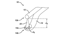
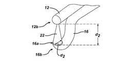
図1A〜図2Bは、外科用流体ジェット切断器械10の一部の例示の一実施形態を示している。図示のように、器械10は主要構成要素として、流体送出管12、第1の吸出管14および第2の吸出管16を有する。第1の吸出管14および第2の吸出管16は、所望の形態の吸出管14,16を使用意図に基づいて選択できるよう流体送出管12に選択的にかつ取外し可能に嵌合できる。特に、図1Aは、流体送出管12に結合された第1の吸出管14を示している。この例示の実施形態では、第1の吸出管14は、組織の塊状除去を可能にするようになっている。図1B、図2Aおよび図2Bでは、第1の吸出管14は、取り外され、これに代えて第2の吸出管16が用いられており、この第2の吸出管は、流体送出管12に結合された状態で示されている。この例示の実施形態では、第2の吸出管16は、組織の高精度彫刻を可能にするようになっている。
1A-2B illustrate one exemplary embodiment of a portion of a surgical fluid
流体送出管12は、種々の形態のものであってよいが、例示の一実施形態では、この流体送出管は、近位端部(図示せず)、遠位端部12bおよびこれを貫通して延びる内部管腔12c(図2Bに示す)を備えた全体として細長い形状のものである。流体送出管12の近位端部は、流体を流体送出管12に送り出す高圧液体源、例えば高圧ポンプ又は液体ディスペンサに結合されるよう設計されたものであるのがよい。流体送出管12は、その遠位端部のところに形成されていて、高圧流体ジェット22を形成して送り出すノズル18(図2Bに示す)をさらに有するのがよい。ノズルは、流体送出管12の近位端部を高圧流体源に結合すると、流体送出管12を通って流体をノズルに送り出すことができるような内部管腔12cと連通状態にあり、ノズルは、特定の寸法形状の流体ジェット22を形成する。
The
各吸出管14,16も又、種々の形態のものであってよいが、例示の一実施形態では、各管14,16は、近位端部(図示せず)、遠位端部14b,16bおよびこの少なくとも一部を貫通して延びる内部管腔を備えた実質的に細長い形状のものである。図1A〜図2Bには示していないが、各吸出管14,16の近位端部は、管14,16を器械10に結合したときに、吸出管14,16を通って吸出される流体および組織を捕集する吸引源、例えば真空ポンプ、吸引装置又は廃棄物キャニスタに直接的又は間接的に結合されるよう構成されたものであるのがよい。各管14,16の遠位端部14b,16bも又、種々の形態のものであってよい。しかしながら、図示した例示の実施形態では、各吸出管14,16は、流体ジェット22およびこの中に含まれた組織を受け入れる吸出ポート14a,16aを有する。吸出ポート14a,16aは、組織を含んだ流体ジェットを捕集できるよう各吸出管14,16を貫通して延びる内部管腔14c,16c内へ延びるのがよい。各吸出ポート14a,16aの寸法形状は、以下に詳細に説明するようにこれ又様々であってよい。図1A〜図2Bに示す実施形態では、各吸出ポート14a,16aの形状は実質的に円形である。
Each
さらに図1Aおよび図1Bに示すように、例示の実施形態では、各吸出ポート14a,16aは、ノズル18から距離d1,d2を置くと共にこれに対向して位置決めされるようになっているのがよい。これは、例えば、各吸出管14,16の遠位端部14b,16bに形成された湾曲部により達成でき、したがって各吸出管14,16を流体送出管12に結合すると、各管14,16の遠位端部14b,16bは、図1Aおよび図1Bに示すように流体送出管12の遠位端部12bから距離d1,d2を置いて位置するようになっている。図示していないが、さらに又は変形例として、流体送出管12に湾曲部を形成してもよい。当業者であれば理解されるように、ノズルと各吸出ポート14a,16aとの間の距離d1,d2は、互いにばらつきがあってよく、又、流体ジェットの寸法に応じてばらつきがあってよい。
Further, as shown in FIGS. 1A and 1B, in the exemplary embodiment, each of the
上述したように、各吸出ポート14a,16aは、流体送出管12に選択的にかつ交換可能に嵌合可能であるのがよい。これは、当該技術分野において知られている種々の技術を用いて達成できるが、例示の一実施形態では、器械10は、流体送出管12の少なくとも一部および吸出管14,16のうちの一方を受け入れるようになった外側ハウジング、例えばシース26を有するのがよい。シース26は、事実上任意の寸法形状のものであってよく、又、任意的に器械の把持を容易にする取っ手の形態をしていてもよいが、図示の例示の実施形態では、シース26は、これを貫通して延びていて、流体送出管12および吸出管14,16のうちの一方を受け入れる第1の通路26aおよび第2の通路26bを備えた全体として細長い形状のものである。各吸出管14,16は、第1および第2の通路26a,26b内に取外し可能に設けられるようになっているのがよく、種々の技術を用いると、吸出管14,16を一時的にシース26に嵌合させることができる。例えば、シース26は、吸出管、例えば吸出管16を露出させるよう近位側へ摺動するよう構成されたものであるのがよく、それにより管16を取り外してこれに代えて別の吸出管、例えば吸出管14を用いることができる。次に、シース26を遠位側へ摺動させて、交換管、例えば管14を流体送出管12に対して定位置に係止するのがよい。他の例示の嵌合技術としては、例えば、吸出管14,16を流体送出管に整列させるようになっていて、管14,16の容易な取外しおよび交換を可能にする締り嵌め、スナップ嵌め、係止嵌め合い、キー止め嵌め合い又は任意他の技術が挙げられる。
As described above, each of the
また上述したように、第1および第2の吸出管14,16は、特定の目的に合うようになっていてもよく、かくして、各吸出ポート14a,16aは、種々の形状のものであってよい。例示の一実施形態では、第1の吸出管14および吸出ポート14aは、組織の塊状除去に用いられるよう構成されたものであってよく、これに対し、第2の吸出管16および吸出ポート16aは、組織の高精度彫刻に用いられるよう構成されたものであってよい。具体的に説明すると、第1の吸出管14は、例えば開口部を横切って測定した直径d1の寸法のような、断面積又は広がりを備えた吸出ポート14aを有するのがよく、これは、第2の吸出ポート16aの、例えばその開口部を横切って測定した直径d2の寸法のような、断面積又は広がりよりも大きい。第1の吸出ポート14aは又、吸出ポート14aの開口部を横切って受け入れられたときに測定して、ノズル18により形成される流体ジェット22の寸法よりも大きな寸法を有するのがよく、第2の吸出ポート16aは、吸出ポート16aの開口部を横切って受け入れられたときに測定して、ノズル18により形成される流体ジェット22の寸法と実質的に同じ又はこれよりも僅かに大きい寸法を有するのがよい。第1の吸出ポート14aの寸法が比較的大きいと、組織の高精度彫刻が妨げられる場合があるが、これは、以下に詳細に説明するように組織の塊状除去を可能にすることになる。これとは逆に、第2の吸出ポート16aの寸法が比較的小さいと、以下に詳細に説明するように組織の高精度彫刻が可能になる。
Further, as described above, the first and
各吸出ポート14a,16aの寸法は様々であってよいが、例示の一実施形態では、各吸出ポート14a,16aは、流体ジェット22が吸出ポート14a,16aの所定の面積を占めるように形作られたものであるのがよい。この所定の面積は、使用意図に応じて様々であってよいが、例示の一実施形態では、流体ジェット22は、第1の吸出管14の吸出ポート14aの一部、例えば80%未満、より好ましくは約50%〜約60%以下を占めるに過ぎないのがよく、他方、この流体ジェットは、第2の吸出管16の吸出ポート16aの実質的に全て、例えば約90%以上を占めるのがよい。かかる構成により、第2の吸出管16は、比較的小さな寸法を有することができ、かくして、流体ジェット22を以下に詳細に説明するように管16からの妨害を受けないで組織表面に対して接線方向に位置決めすることができる。
Although the size of each
上述したように、流体ジェット22により占められるべき各吸出ポート14a,16aの所望の面積は、流体ジェット22の寸法、ノズル18と各吸出ポート14a,16aとの間の距離d1,d2に応じて様々であってよい。例示の一実施形態では、流体ジェット22は、図3に示すように円錐角Aを有するよう形作られたものであるのがよく、この円錐角Aは、約15゜〜約20゜、より好ましくは約17゜〜19゜であり、距離d1,d2は、約1mm〜5mmであるのがよい。ノズル18と各吸出ポート14a,16aとの間の距離d1,d2は、同一であってもよく、或いは、任意的にばらつきがあってもよい。流体ジェット22の圧力も又、ばらつきがあってよいが、例示の実施形態では、流体ジェット22は、約1,000PSI〜約20,000PSI、より好ましくは、5,000PSI〜15,000PSIの圧力で送り出される。
As described above, each
使用に当たり、第1の吸出管14を組織の塊状除去に用いることができ、第2の吸出管16を組織の高精度彫刻に用いることができる。まず最初に、図3を参照すると、流体ジェット22が、詳細に示されており、この流体ジェット22は、図示のように、その長さに沿ってその周囲周りに形成された剪断切断平面およびこの切断平面の内部に位置する浸軟ゾーンを有する。第1の吸出管14により、流体ジェット22を剪断切断平面が組織表面に対して横方向に位置し、即ち、組織表面内へ延びるよう位置決めすることができ、かくして流体ジェット22を組織の塊状除去に用いることができ、したがって浸軟ゾーン内の組織が浸軟されるようになっている。次に、第1の吸出管14を取り外し、これに代えて第2の吸出管16を用いることができ、この第2の吸出管により、流体ジェット22を剪断切断平面が組織表面に対して実質的に接線方向に位置するように位置決めすることができ、かくして流体ジェット22を組織の高精度彫刻に用いることができる。図4は、流体送出管12および吸出管16に類似した流体送出管12′および吸出管16′を備えた一実施形態としての流体ジェット切断器械10′を示しており、さらに、剪断切断平面が組織表面に対して実質的に接線方向に位置するよう位置決めされた流体ジェット22′を示しており、かくして、流体ジェット22′を組織の高精度彫刻に用いることができるようになっている。したがって、選択的に交換可能な吸出管14,16を設けることにより、流体ジェット22を組織の塊状除去に用いたり組織の高精度彫刻に用いたりするよう選択的に位置決めできる。
In use, the
当業者であれば、上述の実施形態に基づく本発明の別の特徴および利点を理解されよう。したがって、本発明は、特許請求の範囲の記載事項を除き、具体的に図示して説明した形態によっては限定されない。本明細書において引用される全ての刊行物および文献の記載内容全体を参照によりここに引用する。 One skilled in the art will appreciate further features and advantages of the invention based on the above-described embodiments. Therefore, the present invention is not limited by the embodiments specifically illustrated and described, except for the matters described in the claims. The entire contents of all publications and references cited herein are hereby incorporated by reference.
〔実施の態様〕
本発明の具体的な実施態様は、次の通りである。
(1)流体ジェット切断器械であって、
流体ジェットを形成するノズルを備えた流体送出管と、
前記流体送出管に選択的かつ取外し可能に嵌合できる複数本の吸出管と、を有し、
各前記吸出管は、前記ノズルにより形成された流体ジェットを捕集するように前記ノズルに対向すると共にこれから間隔を置いて位置決めされるようになった吸出ポートを有し、
各前記吸出管の前記吸出ポートは、前記吸出ポートの開口部を横切って測定した断面積が、互いに異なっている、流体ジェット切断器械。
(2)実施態様(1)記載の流体ジェット切断器械であって、
前記複数本の吸出管は、第1の吸出ポートを備えた第1の吸出管および第2の吸出ポートを備えた第2の吸出管を含み、
前記第1の吸出ポートの前記断面積は、前記第2の吸出ポートの前記断面積よりも大きい、流体ジェット切断器械。
(3)実施態様(2)記載の流体ジェット切断器械であって、
前記第1の吸出ポートは、前記第1の吸出ポートの開口部を横切って測定した直径が、前記ノズルにより形成される流体ジェットの最大直径よりも実質的に大きく、
前記第2の吸出ポートは、前記第2の吸出ポートの開口部を横切って測定した直径が、前記ノズルにより形成される前記流体ジェットの最大直径とほぼ同じである、流体ジェット切断器械。
(4)実施態様(2)記載の流体ジェット切断器械であって、
前記第1の吸出管は、組織の塊状除去を可能にするようになっており、
前記第2の吸出管は、組織の高精度彫刻を可能にするようになっている、流体ジェット切断器械。
(5)実施態様(1)記載の流体ジェット切断器械であって、
前記吸出管を選択的に交換できるようにするために前記流体送出管および前記複数本の吸出管のうちの1本の周りに摺動自在に設けられたシースをさらに有する、流体ジェット切断器械。
Embodiment
Specific embodiments of the present invention are as follows.
(1) A fluid jet cutting machine,
A fluid delivery tube with a nozzle forming a fluid jet;
A plurality of suction pipes that can be selectively and detachably fitted to the fluid delivery pipe,
Each said suction pipe has a suction port which is positioned oppositely and spaced from said nozzle so as to collect a fluid jet formed by said nozzle;
The fluid jet cutting instrument, wherein the suction ports of each of the suction pipes have different cross-sectional areas measured across the opening of the suction port.
(2) The fluid jet cutting device according to the embodiment (1),
The plurality of suction pipes include a first suction pipe having a first suction port and a second suction pipe having a second suction port;
The fluid jet cutting instrument, wherein the cross-sectional area of the first suction port is greater than the cross-sectional area of the second suction port.
(3) A fluid jet cutting device according to embodiment (2),
The first suction port has a diameter measured across the opening of the first suction port substantially greater than a maximum diameter of a fluid jet formed by the nozzle;
The fluid jet cutting instrument, wherein the second suction port has a diameter measured across the opening of the second suction port that is approximately the same as the maximum diameter of the fluid jet formed by the nozzle.
(4) The fluid jet cutting device according to the embodiment (2),
The first suction tube is adapted to allow removal of a mass of tissue;
The second jet tube is a fluid jet cutting instrument adapted to allow high precision engraving of tissue.
(5) The fluid jet cutting device according to the embodiment (1),
A fluid jet cutting instrument further comprising a sheath slidably disposed about the fluid delivery tube and one of the plurality of suction tubes to allow the suction tube to be selectively replaced.
(6)実施態様(1)記載の流体ジェット切断器械であって、
前記複数本の吸出管の各々の前記吸出ポートは、前記吸出管を貫通して形成された管腔内に延びる実質的に円形の開口部を有する、流体ジェット切断器械。
(7)外科用流体ジェット切断器械であって、
流体によって形成するノズルを備えた流体送出管と、
前記流体送出管に選択的かつ取外し可能に嵌合可能な第1および第2の吸出管と、を有し、
各前記吸出管は、前記ノズルにより形成される流体ジェットを受け入れるように前記ノズルと対向して位置決めされるようになったジェット受入れ開口部を有し、
前記第1の吸出管は、組織の塊状除去を可能にするようになっており、
前記第2の吸出管は、組織の高精度彫刻を可能にするようになっている、流体ジェット切断器械。
(8)実施態様(7)記載の流体ジェット切断器械であって、
前記ノズルにより形成される流体ジェットは、前記流体ジェットを受入れ開口部のところで測定した断面積が、前記第1の吸出管の前記流体ジェット受入れ開口部の断面積よりも実質的に小さく、かつ前記第2の吸出管の前記流体ジェット受入れ開口部の断面積とほぼ同じである、流体ジェット切断器械。
(9)実施態様(8)記載の流体ジェット切断器械であって、
前記第1の吸出管は、前記ノズルにより形成される流体ジェットを前記第1の吸出管の実質的に中間部分で受け入れるようになっている、流体ジェット切断器械。
(10)実施態様(7)記載の流体ジェット切断器械であって、
前記流体送出管の周りに設けられていて、前記第1および第2の吸出管のうちの一方を選択的かつ取外し可能に受け入れるようになったシースをさらに有する、流体ジェット切断器械。
(6) The fluid jet cutting device according to the embodiment (1),
The fluid jet cutting instrument, wherein the suction port of each of the plurality of suction tubes has a substantially circular opening extending into a lumen formed through the suction tube.
(7) a surgical fluid jet cutting instrument,
A fluid delivery tube with a nozzle formed by the fluid;
First and second suction pipes that can be selectively and detachably fitted to the fluid delivery pipe;
Each said suction tube has a jet receiving opening adapted to be positioned opposite said nozzle to receive a fluid jet formed by said nozzle;
The first suction tube is adapted to allow removal of a mass of tissue;
The second jet tube is a fluid jet cutting instrument adapted to allow high precision engraving of tissue.
(8) The fluid jet cutting device according to the embodiment (7),
The fluid jet formed by the nozzle has a cross-sectional area measured at the receiving opening of the fluid jet that is substantially smaller than a cross-sectional area of the fluid jet receiving opening of the first suction pipe, and A fluid jet cutting instrument having approximately the same cross-sectional area of the fluid jet receiving opening of a second suction tube.
(9) The fluid jet cutting device according to the embodiment (8),
The fluid jet cutting instrument, wherein the first suction tube is adapted to receive a fluid jet formed by the nozzle at a substantially intermediate portion of the first suction tube.
(10) The fluid jet cutting device according to the embodiment (7),
A fluid jet cutting instrument further comprising a sheath provided around the fluid delivery tube and adapted to selectively and removably receive one of the first and second suction tubes.
(11)実施態様(10)記載の流体ジェット切断器械であって、
前記シースは、前記流体送出管に対して摺動自在である、流体ジェット切断器械。
(12)実施態様(7)記載の流体ジェット切断器械であって、
前記第1および第2の吸出管の前記吸出ポートは、前記吸出管を貫通して形成された管腔内へ延びる実質的に円形の開口部を有する、流体ジェット切断器械。
(13)組織を除去する方法であって、
高圧流体ジェットを組織表面に隣接して位置決めして組織を塊状で除去する段階であって、前記高圧流体ジェットおよび前記組織は、前記第1の吸出管に形成された第1の吸出ポート内に捕集され、前記第1の吸出ポートは、前記第1の吸出ポートを開口部を横切って測定した断面積が前記高圧流体ジェットの断面積よりも実質的に大きい、段階と、
前記第1の吸出管に代えて第2の排気ポートを備えた第2の吸出管を用いる段階であって、前記第2の吸出ポートは、前記第2の吸出ポートの開口部を横切って測定した断面積が前記高圧流体ジェットの断面積とほぼ同じである、段階と、
前記高圧流体ジェットを前記組織表面に隣接して位置決めして前記組織を正確に彫刻する段階であって、前記高圧流体ジェットおよび前記組織は、前記第2の吸出管の前記第2の吸出ポート内に捕集される、段階と、を有する方法。
(14)実施態様(13)記載の方法であって、
前記高圧流体ジェットは、流体送出管に設けられたノズルにより形成され、
前記第1および第2の吸出管は、前記流体送出管に選択的かつ取外し可能に嵌合できる、方法。
(15)実施態様(13)記載の方法であって、
前記高圧流体ジェットの切断剪断平面は、前記組織が塊状で除去されるとき、組織表面に対して実質的に横方向に位置決めされ、
前記流体ジェットの前記切断剪断平面は、前記組織が正確に彫刻されるとき、前記組織表面に対して実質的に接線方向に位置決めされる、方法。
(11) The fluid jet cutting device according to the embodiment (10),
A fluid jet cutting instrument, wherein the sheath is slidable relative to the fluid delivery tube.
(12) The fluid jet cutting device according to the embodiment (7),
The fluid jet cutting instrument, wherein the suction port of the first and second suction tubes has a substantially circular opening extending into a lumen formed through the suction tube.
(13) A method for removing tissue,
Positioning a high pressure fluid jet adjacent to the tissue surface to remove the tissue in bulk, wherein the high pressure fluid jet and the tissue are in a first suction port formed in the first suction tube; And wherein the first suction port has a cross-sectional area measured across the opening of the first suction port that is substantially greater than a cross-sectional area of the high-pressure fluid jet; and
Using a second suction pipe with a second exhaust port instead of the first suction pipe, wherein the second suction port is measured across the opening of the second suction port. A cross-sectional area that is substantially the same as the cross-sectional area of the high-pressure fluid jet; and
Positioning the high pressure fluid jet adjacent to the tissue surface to accurately engrave the tissue, wherein the high pressure fluid jet and the tissue are in the second suction port of the second suction tube. Collected in a stage.
(14) The method according to embodiment (13),
The high-pressure fluid jet is formed by a nozzle provided in a fluid delivery pipe,
The method wherein the first and second suction tubes can be selectively and removably fitted to the fluid delivery tube.
(15) The method according to embodiment (13),
The cutting shear plane of the high pressure fluid jet is positioned substantially transverse to the tissue surface when the tissue is removed in bulk,
The method wherein the cutting shear plane of the fluid jet is positioned substantially tangential to the tissue surface when the tissue is accurately engraved.
(16)実施態様(15)記載の方法であって、
前記組織は、塊状除去中に浸軟され、前記組織は、高精度彫刻中に切断される、方法。
(17)組織を除去する方法であって、
第1の吸出管を流体送出管に結合して、前記第1の吸出管に形成された第1の吸出ポートを前記流体送出管に設けられたノズルに対向して位置決めする段階であって、前記第1の吸出管は、組織の塊状除去を可能にするようになっている、段階と、
前記ノズルにより形成される流体ジェットを用いて組織を塊状で除去する段階であって、前記流体ジェットおよび前記組織は、前記第1の吸出管の前記第1の吸出ポート内に捕集される、段階と、
前記第1の吸出管に代えて第2の吸出管を用いて前記第2の吸出管に形成された第2の吸出ポートを前記流体送出管の前記ノズルに対向して位置決めする段階であって、前記第2の吸出管は、組織の高精度彫刻を可能にするようになっている、段階と、
前記ノズルにより形成される流体ジェットを用いて前記組織表面を高精度彫刻する段階であって、前記流体ジェットおよび前記組織は、前記第2の吸出管の前記第2の吸出ポート内に捕集される、段階と、を有する方法。
(18)実施態様(17)記載の方法であって、
前記第1の吸出ポートは、前記第1の吸出ポートの開口部を横切って測定した断面積が前記流体ジェットの断面積よりも実質的に大きく、
前記第2の吸出ポートは、前記第2の吸出ポートの開口部を横切って測定した断面積が前記流体ジェットの断面積とほぼ同じである、方法。
(19)実施態様(17)記載の方法であって、
前記第1の吸出管に代えて前記第2の吸出管を用いる前記段階は、前記第1の吸出管の周りに設けられたシースを摺動自在に取り外す段階と、前記第1の吸出管を取り外す段階と、前記第2の吸出管を前記流体送出管に対して位置決めする段階と、前記シースを前記第2の吸出管および前記流体送出管上に沿って摺動させる段階と、を含む、方法。
(16) The method according to embodiment (15),
The method wherein the tissue is macerated during mass removal and the tissue is cut during precision engraving.
(17) A method for removing tissue,
Coupling a first suction pipe to a fluid delivery pipe and positioning a first suction port formed in the first suction pipe against a nozzle provided in the fluid delivery pipe; The first suction tube is adapted to allow removal of a mass of tissue; and
Removing tissue in bulk using a fluid jet formed by the nozzle, wherein the fluid jet and the tissue are collected in the first suction port of the first suction tube; Stages,
Positioning a second suction port formed in the second suction pipe opposite to the nozzle of the fluid delivery pipe using a second suction pipe instead of the first suction pipe; The second suction tube is adapted to allow high precision engraving of tissue; and
High precision engraving of the tissue surface using a fluid jet formed by the nozzle, wherein the fluid jet and the tissue are collected in the second suction port of the second suction pipe. And a step comprising:
(18) The method according to embodiment (17),
The first suction port has a cross-sectional area measured across the opening of the first suction port substantially greater than the cross-sectional area of the fluid jet;
The method wherein the second suction port has a cross-sectional area measured across the opening of the second suction port that is substantially the same as the cross-sectional area of the fluid jet.
(19) The method according to embodiment (17),
The step of using the second suction pipe in place of the first suction pipe includes a step of slidably removing a sheath provided around the first suction pipe, and a step of removing the first suction pipe. Removing, positioning the second suction tube relative to the fluid delivery tube, and sliding the sheath along the second suction tube and the fluid delivery tube. Method.
10 外科用流体ジェット切断器械
12 流体送出管
12c 内部管腔
14 第1の吸出管
14a 吸出ポート
16 第2の吸出管
18 ノズル
22 高圧流体ジェット
26 シース
DESCRIPTION OF
Claims (13)
流体ジェットを形成するノズルを備えた流体送出管と、
前記流体送出管に選択的かつ取外し可能に嵌合できる複数本の吸出管と、を有し、
各前記吸出管は、前記ノズルにより形成された流体ジェットを捕集するように前記ノズルに対向すると共にこれから間隔を置いて位置決めされるようになった吸出ポートを有し、
各前記吸出管の前記吸出ポートは、前記吸出ポートの開口部を横切って測定した断面積が、互いに異なっている、流体ジェット切断器械。 A fluid jet cutting machine,
A fluid delivery tube with a nozzle forming a fluid jet;
A plurality of suction pipes that can be selectively and detachably fitted to the fluid delivery pipe,
Each said suction pipe has a suction port which is positioned oppositely and spaced from said nozzle so as to collect a fluid jet formed by said nozzle;
The fluid jet cutting instrument, wherein the suction ports of each of the suction pipes have different cross-sectional areas measured across the opening of the suction port.
前記複数本の吸出管は、第1の吸出ポートを備えた第1の吸出管および第2の吸出ポートを備えた第2の吸出管を含み、
前記第1の吸出ポートの前記断面積は、前記第2の吸出ポートの前記断面積よりも大きい、流体ジェット切断器械。 A fluid jet cutting instrument according to claim 1, comprising:
The plurality of suction pipes include a first suction pipe having a first suction port and a second suction pipe having a second suction port;
The fluid jet cutting instrument, wherein the cross-sectional area of the first suction port is greater than the cross-sectional area of the second suction port.
前記第1の吸出ポートは、前記第1の吸出ポートの開口部を横切って測定した直径が、前記ノズルにより形成される流体ジェットの最大直径よりも実質的に大きく、
前記第2の吸出ポートは、前記第2の吸出ポートの開口部を横切って測定した直径が、前記ノズルにより形成される前記流体ジェットの最大直径とほぼ同じである、流体ジェット切断器械。 A fluid jet cutting instrument according to claim 2 comprising:
The first suction port has a diameter measured across the opening of the first suction port substantially greater than a maximum diameter of a fluid jet formed by the nozzle;
The fluid jet cutting instrument, wherein the second suction port has a diameter measured across the opening of the second suction port that is approximately the same as the maximum diameter of the fluid jet formed by the nozzle.
前記第1の吸出管は、組織の塊状除去を可能にするようになっており、
前記第2の吸出管は、組織の高精度彫刻を可能にするようになっている、流体ジェット切断器械。 A fluid jet cutting instrument according to claim 2 comprising:
The first suction tube is adapted to allow removal of a mass of tissue;
The second jet tube is a fluid jet cutting instrument adapted to allow high precision engraving of tissue.
前記吸出管を選択的に交換できるようにするために前記流体送出管および前記複数本の吸出管のうちの1本の周りに摺動自在に設けられたシースをさらに有する、流体ジェット切断器械。 A fluid jet cutting instrument according to claim 1, comprising:
A fluid jet cutting instrument further comprising a sheath slidably disposed about the fluid delivery tube and one of the plurality of suction tubes to allow the suction tube to be selectively replaced.
前記複数本の吸出管の各々の前記吸出ポートは、前記吸出管を貫通して形成された管腔内に延びる実質的に円形の開口部を有する、流体ジェット切断器械。 A fluid jet cutting instrument according to claim 1, comprising:
The fluid jet cutting instrument, wherein the suction port of each of the plurality of suction tubes has a substantially circular opening extending into a lumen formed through the suction tube.
流体によって形成するノズルを備えた流体送出管と、
前記流体送出管に選択的かつ取外し可能に嵌合可能な第1および第2の吸出管と、を有し、
各前記吸出管は、前記ノズルにより形成される流体ジェットを受け入れるように前記ノズルと対向して位置決めされるようになったジェット受入れ開口部を有し、
前記第1の吸出管は、組織の塊状除去を可能にするようになっており、
前記第2の吸出管は、組織の高精度彫刻を可能にするようになっている、流体ジェット切断器械。 A surgical fluid jet cutting instrument,
A fluid delivery tube with a nozzle formed by the fluid;
First and second suction pipes that can be selectively and detachably fitted to the fluid delivery pipe;
Each said suction tube has a jet receiving opening adapted to be positioned opposite said nozzle to receive a fluid jet formed by said nozzle;
The first suction tube is adapted to allow removal of a mass of tissue;
The second jet tube is a fluid jet cutting instrument adapted to allow high precision engraving of tissue.
前記ノズルにより形成される流体ジェットは、前記流体ジェットを受入れ開口部のところで測定した断面積が、前記第1の吸出管の前記流体ジェット受入れ開口部の断面積よりも実質的に小さく、かつ前記第2の吸出管の前記流体ジェット受入れ開口部の断面積とほぼ同じである、流体ジェット切断器械。 A fluid jet cutting instrument according to claim 7, comprising:
The fluid jet formed by the nozzle has a cross-sectional area measured at the receiving opening of the fluid jet that is substantially smaller than a cross-sectional area of the fluid jet receiving opening of the first suction pipe, and A fluid jet cutting instrument having approximately the same cross-sectional area of the fluid jet receiving opening of a second suction tube.
前記第1の吸出管は、前記ノズルにより形成される流体ジェットを前記第1の吸出管の実質的に中間部分で受け入れるようになっている、流体ジェット切断器械。 A fluid jet cutting instrument according to claim 8, comprising:
The fluid jet cutting instrument, wherein the first suction tube is adapted to receive a fluid jet formed by the nozzle at a substantially intermediate portion of the first suction tube.
前記流体送出管の周りに設けられていて、前記第1および第2の吸出管のうちの一方を選択的かつ取外し可能に受け入れるようになったシースをさらに有する、流体ジェット切断器械。 A fluid jet cutting instrument according to claim 7, comprising:
A fluid jet cutting instrument further comprising a sheath provided around the fluid delivery tube and adapted to selectively and removably receive one of the first and second suction tubes.
前記シースは、前記流体送出管に対して摺動自在である、流体ジェット切断器械。 A fluid jet cutting instrument according to claim 10 comprising:
A fluid jet cutting instrument, wherein the sheath is slidable relative to the fluid delivery tube.
前記第1および第2の吸出管の前記吸出ポートは、前記吸出管を貫通して形成された管腔内へ延びる実質的に円形の開口部を有する、流体ジェット切断器械。 A fluid jet cutting instrument according to claim 7, comprising:
The fluid jet cutting instrument, wherein the suction port of the first and second suction tubes has a substantially circular opening extending into a lumen formed through the suction tube.
高圧流体ジェットを組織表面に隣接して位置決めして組織を塊状で除去する段階であって、前記高圧流体ジェットおよび前記組織は、前記第1の吸出管に形成された第1の吸出ポート内に捕集され、前記第1の吸出ポートは、前記第1の吸出ポートを開口部を横切って測定した断面積が前記高圧流体ジェットの断面積よりも実質的に大きい、段階と、
前記第1の吸出管に代えて第2の排気ポートを備えた第2の吸出管を用いる段階であって、前記第2の吸出ポートは、前記第2の吸出ポートの開口部を横切って測定した断面積が前記高圧流体ジェットの断面積とほぼ同じである、段階と、
前記高圧流体ジェットを前記組織表面に隣接して位置決めして前記組織を正確に彫刻する段階であって、前記高圧流体ジェットおよび前記組織は、前記第2の吸出管の前記第2の吸出ポート内に捕集される、段階と、を有する方法。 A method of removing tissue,
Positioning a high pressure fluid jet adjacent to the tissue surface to remove the tissue in bulk, wherein the high pressure fluid jet and the tissue are in a first suction port formed in the first suction tube; Collected and the first suction port has a cross-sectional area measured across the opening of the first suction port that is substantially greater than a cross-sectional area of the high pressure fluid jet; and
Using a second suction pipe with a second exhaust port instead of the first suction pipe, wherein the second suction port is measured across the opening of the second suction port. A cross-sectional area that is substantially the same as the cross-sectional area of the high-pressure fluid jet; and
Positioning the high pressure fluid jet adjacent to the tissue surface to accurately engrave the tissue, wherein the high pressure fluid jet and the tissue are within the second suction port of the second suction tube. Collected in a stage.
Applications Claiming Priority (1)
| Application Number | Priority Date | Filing Date | Title |
|---|---|---|---|
| US10/905,044 US20060129086A1 (en) | 2004-12-13 | 2004-12-13 | Interchangeable tissue macerating and sculpting methods and devices |
Publications (2)
| Publication Number | Publication Date |
|---|---|
| JP2006167461A true JP2006167461A (en) | 2006-06-29 |
| JP2006167461A5 JP2006167461A5 (en) | 2006-10-12 |
Family
ID=36284208
Family Applications (1)
| Application Number | Title | Priority Date | Filing Date |
|---|---|---|---|
| JP2005358072A Abandoned JP2006167461A (en) | 2004-12-13 | 2005-12-12 | Interchangeable tissue macerating and sculpting methods and devices |
Country Status (5)
| Country | Link |
|---|---|
| US (1) | US20060129086A1 (en) |
| EP (1) | EP1671595A3 (en) |
| JP (1) | JP2006167461A (en) |
| AU (1) | AU2005242152B2 (en) |
| CA (1) | CA2529014C (en) |
Cited By (2)
| Publication number | Priority date | Publication date | Assignee | Title |
|---|---|---|---|---|
| WO2011046142A1 (en) * | 2009-10-14 | 2011-04-21 | 三菱重工業株式会社 | Stringer manufacturing method |
| US9193036B2 (en) | 2011-04-13 | 2015-11-24 | Mitsubishi Heavy Industries, Ltd | Abrasive water-jet machining device |
Families Citing this family (7)
| Publication number | Priority date | Publication date | Assignee | Title |
|---|---|---|---|---|
| US7794408B2 (en) | 2003-03-28 | 2010-09-14 | Ethicon, Inc. | Tissue collection device and methods |
| US8034003B2 (en) | 2003-09-11 | 2011-10-11 | Depuy Mitek, Inc. | Tissue extraction and collection device |
| US7611473B2 (en) | 2003-09-11 | 2009-11-03 | Ethicon, Inc. | Tissue extraction and maceration device |
| US20060100569A1 (en) * | 2004-11-11 | 2006-05-11 | Depuy Mitek, Inc | Methods and devices for selective bulk removal and precision sculpting of tissue |
| US10492821B2 (en) | 2016-06-24 | 2019-12-03 | Hydrocision, Inc. | Selective tissue removal treatment device |
| EP3500192A4 (en) * | 2016-06-24 | 2020-05-13 | Hydrocision, Inc. | Selective tissue removal treatment device |
| WO2018231983A1 (en) | 2017-06-13 | 2018-12-20 | Board Of Regents Of The University Of Nebraska | Surgical devices and methods |
Family Cites Families (13)
| Publication number | Priority date | Publication date | Assignee | Title |
|---|---|---|---|---|
| DE8426270U1 (en) * | 1984-09-06 | 1985-02-14 | Veltrup, Elmar Michael, Dipl.-Ing., 4150 Krefeld | DEVICE FOR REMOVING SOLID BODIES OR DEPOSITS FROM BODY VESSELS |
| CA2048120A1 (en) * | 1990-08-06 | 1992-02-07 | William J. Drasler | Thrombectomy method and device |
| DE4126886A1 (en) * | 1991-08-14 | 1993-02-18 | Hp Medica Gmbh | RINSING CATHETER |
| US5186714A (en) * | 1992-05-18 | 1993-02-16 | Yab Revo-Tech Inc. | Multifunctional surgical instrument |
| US6135977A (en) * | 1994-02-16 | 2000-10-24 | Possis Medical, Inc. | Rheolytic catheter |
| US5527330A (en) * | 1994-08-18 | 1996-06-18 | United States Surgical Corporation | Fluid cutting instrument |
| US5871462A (en) * | 1995-06-07 | 1999-02-16 | Hydrocision, Inc. | Method for using a fluid jet cutting system |
| US5944686A (en) * | 1995-06-07 | 1999-08-31 | Hydrocision, Inc. | Instrument for creating a fluid jet |
| US5788667A (en) * | 1996-07-19 | 1998-08-04 | Stoller; Glenn | Fluid jet vitrectomy device and method for use |
| US6375635B1 (en) * | 1999-05-18 | 2002-04-23 | Hydrocision, Inc. | Fluid jet surgical instruments |
| US6511493B1 (en) * | 2000-01-10 | 2003-01-28 | Hydrocision, Inc. | Liquid jet-powered surgical instruments |
| ES2290358T3 (en) * | 2001-11-21 | 2008-02-16 | Hydrocision, Inc. | SURGICAL INSTRUMENTS WITH LIQUID SPLASH, WHICH INCLUDE CHANNEL OPENINGS ALONGED THROUGH THE SPLIT. |
| US8162966B2 (en) * | 2002-10-25 | 2012-04-24 | Hydrocision, Inc. | Surgical devices incorporating liquid jet assisted tissue manipulation and methods for their use |
-
2004
- 2004-12-13 US US10/905,044 patent/US20060129086A1/en not_active Abandoned
-
2005
- 2005-12-06 CA CA002529014A patent/CA2529014C/en not_active Expired - Fee Related
- 2005-12-07 AU AU2005242152A patent/AU2005242152B2/en not_active Ceased
- 2005-12-12 JP JP2005358072A patent/JP2006167461A/en not_active Abandoned
- 2005-12-13 EP EP05257636A patent/EP1671595A3/en not_active Withdrawn
Cited By (5)
| Publication number | Priority date | Publication date | Assignee | Title |
|---|---|---|---|---|
| WO2011046142A1 (en) * | 2009-10-14 | 2011-04-21 | 三菱重工業株式会社 | Stringer manufacturing method |
| JP2011084138A (en) * | 2009-10-14 | 2011-04-28 | Mitsubishi Heavy Ind Ltd | Method for manufacturing stringer |
| KR101345958B1 (en) | 2009-10-14 | 2014-01-02 | 플로우 저팬 코포레이션 | stringer manufacturing method |
| US9149909B2 (en) | 2009-10-14 | 2015-10-06 | Mitsubishi Heavy Industries, Ltd. | Stringer manufacturing method |
| US9193036B2 (en) | 2011-04-13 | 2015-11-24 | Mitsubishi Heavy Industries, Ltd | Abrasive water-jet machining device |
Also Published As
| Publication number | Publication date |
|---|---|
| CA2529014C (en) | 2009-10-13 |
| AU2005242152B2 (en) | 2008-10-16 |
| US20060129086A1 (en) | 2006-06-15 |
| EP1671595A2 (en) | 2006-06-21 |
| CA2529014A1 (en) | 2006-06-13 |
| EP1671595A3 (en) | 2006-07-12 |
| AU2005242152A1 (en) | 2006-06-29 |
Similar Documents
| Publication | Publication Date | Title |
|---|---|---|
| JP2006167461A (en) | Interchangeable tissue macerating and sculpting methods and devices | |
| JP5866421B2 (en) | Surgical cutting instrument with distal suction function | |
| US6423078B1 (en) | Dermabrasion instrument, instrument assembly and method | |
| EP2412320A1 (en) | Labrum retracting burr | |
| JP2006136727A (en) | Method and device for selective bulk removal and precision sculpting of tissue | |
| CN101534760B (en) | Phacoemulsification cannula with improved purchase | |
| TW427896B (en) | Surgical reamer | |
| CN107949343A (en) | For extracting the device and its application method of root pipe | |
| JP2006503682A5 (en) | ||
| JP2006503682A (en) | Surgical device incorporating liquid jet assisted tissue manipulation and use thereof | |
| JP2001514559A (en) | Separate suction degreasing and fat injection device | |
| US20070010823A1 (en) | Arthroscopic shaver system | |
| EP0444071A1 (en) | Surgical instrument | |
| US20070060936A1 (en) | Surgical abrader with clear hood | |
| JP2019503802A (en) | Suction irrigation device | |
| US20090170052A1 (en) | Dental Apparatus for Irrigating Root Canals of Teeth and Method for Irrigating Root Canals of Teeth | |
| US10709532B2 (en) | Atraumatic high-volume dental evacuation tip | |
| CN106725736A (en) | A kind of endoscope casing tube formula circular cutter | |
| US11026715B2 (en) | Chest cavity suction medical apparatus and method | |
| CN206587013U (en) | A kind of endoscope casing tube formula circular cutter | |
| KR200402827Y1 (en) | Scrape Inhalation Technique Instrument | |
| RU28010U1 (en) | GYNECOLOGICAL INSTRUMENT | |
| RU2069552C1 (en) | Aspiration-irrigation dish | |
| RU2190976C2 (en) | Gynecological instrument | |
| JP2002238835A (en) | Distal end of endoscope for treatment |
Legal Events
| Date | Code | Title | Description |
|---|---|---|---|
| A521 | Written amendment |
Free format text: JAPANESE INTERMEDIATE CODE: A523 Effective date: 20060630 |
|
| A521 | Written amendment |
Free format text: JAPANESE INTERMEDIATE CODE: A523 Effective date: 20060825 |
|
| RD04 | Notification of resignation of power of attorney |
Free format text: JAPANESE INTERMEDIATE CODE: A7424 Effective date: 20071129 |
|
| A621 | Written request for application examination |
Free format text: JAPANESE INTERMEDIATE CODE: A621 Effective date: 20080620 |
|
| RD04 | Notification of resignation of power of attorney |
Free format text: JAPANESE INTERMEDIATE CODE: A7424 Effective date: 20080926 |
|
| A762 | Written abandonment of application |
Free format text: JAPANESE INTERMEDIATE CODE: A762 Effective date: 20090930 |
|
| A521 | Written amendment |
Free format text: JAPANESE INTERMEDIATE CODE: A821 Effective date: 20090930 |