JP2006166328A - Image processing device - Google Patents
Image processing device Download PDFInfo
- Publication number
- JP2006166328A JP2006166328A JP2004358294A JP2004358294A JP2006166328A JP 2006166328 A JP2006166328 A JP 2006166328A JP 2004358294 A JP2004358294 A JP 2004358294A JP 2004358294 A JP2004358294 A JP 2004358294A JP 2006166328 A JP2006166328 A JP 2006166328A
- Authority
- JP
- Japan
- Prior art keywords
- pattern
- processing unit
- data
- processing
- dither
- Prior art date
- Legal status (The legal status is an assumption and is not a legal conclusion. Google has not performed a legal analysis and makes no representation as to the accuracy of the status listed.)
- Withdrawn
Links
Images
Landscapes
- Record Information Processing For Printing (AREA)
- Image Processing (AREA)
- Facsimile Image Signal Circuits (AREA)
Abstract
【課題】 何らかの色で印字されるべき中間調がマスクパターンに遮られて全く印刷されず想定外の印刷結果となる問題を解決することが可能となる。
【解決手段】 中間調をディザ処理する処理系において、コマンドデータを解析し前景パターンと背景色を取得し、背景色を適用した場合に得られる想定HT処理後画像を生成し、前景パターンと作成した背景HT画像を比較し、干渉による背景色抜けのレベルを判断し、背景色抜けのレベルが閾値を越える場合に、抜けのレベルが閾値以下の背景HT画像となるような処理を施すことを特徴とする。
【選択図】 図7
PROBLEM TO BE SOLVED: To solve a problem that a halftone to be printed in any color is blocked by a mask pattern and is not printed at all and an unexpected printing result is obtained.
In a processing system for dithering a halftone, command data is analyzed to obtain a foreground pattern and a background color, an assumed HT-processed image obtained when the background color is applied is generated, and a foreground pattern is created. Compare background HT images, determine the level of background color omission due to interference, and if the background color omission level exceeds the threshold, perform processing that results in a background HT image with the level of omission below the threshold Features.
[Selection] Figure 7
Description
本発明は、画像データに基づいて作成された出力信号を基に印刷媒体上に印字材料を用いて印字処理を行う印刷装置に関するものである。 The present invention relates to a printing apparatus that performs a printing process using a printing material on a printing medium based on an output signal created based on image data.
ホストコンピュータ等のデータ生成装置から印刷データを受信し、装置内部で印刷データを画像データに変換して印刷媒体上に印字処理を施す印刷装置にあって、印刷データに含まれる多値カラーデータを処理する際、多くの印刷装置ではディザ法と呼ばれる擬似中間調表現法を用いることが多い。 A printing device that receives print data from a data generation device such as a host computer, converts the print data into image data inside the device, and performs a printing process on a print medium, wherein multi-value color data included in the print data is received. In processing, many printing apparatuses often use a pseudo halftone expression method called a dither method.
本手法は元画像データ中の1画素が多階調を有する場合に、1画素単階調、あるいは元画像より低い多階調を持つ複数の画素で擬似的に濃度表現する面積階調法である。 This method is an area gray scale method that expresses the density with a single pixel single gradation or multiple pixels with multiple gradations lower than the original image when one pixel in the original image data has multiple gradations. is there.
この時、2値化または多値化に用いるディザパターンは様々閾値配列を持つものが考案されている(特許文献1)。 At this time, dither patterns used for binarization or multilevel conversion have been devised having various threshold arrays (Patent Document 1).
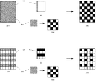
図3は、一般的な印刷データ中、背景にある色を指定された図形オブジェクトの中間調処理を示す概念図である。 FIG. 3 is a conceptual diagram showing halftone processing of a graphic object in which a background color is designated in general print data.
2値化処理を例にとると、印刷データに含まれる“長方形を50%の灰色で塗り潰す図形”(301)が指定された場合、コマンドデータは長方形の輪郭領域を表す前景パターン(302)と、長方形内部を塗り潰す際に使用する背景カラー(303)の組合せで構成される。 Taking the binarization process as an example, when “a figure that fills a rectangle with 50% gray” (301) included in the print data is designated, the command data is a foreground pattern (302) representing a rectangular outline region. And a combination of background colors (303) used when filling the interior of the rectangle.
この時、輪郭領域は長方形そのものであり、また、背景カラーである50%の灰色は、先に述べたディザ法を用いて2値画像として表される(304)。この2値画像を前景パターン内部に並べたものが、擬似的に50%の灰色で塗り潰した長方形の画像データとなる(305)。 At this time, the outline region is a rectangle itself, and the background color of 50% gray is represented as a binary image using the dither method described above (304). This binary image arranged in the foreground pattern becomes rectangular image data that is artificially filled with 50% gray (305).
一方、前景パターンとして指定される領域は、図形の輪郭内のみではなく、輪郭内部を一定のパターンでマスクするためのマスクパターンで指定される場合もある。 On the other hand, the region designated as the foreground pattern may be designated not only within the contour of the figure but also with a mask pattern for masking the inside of the contour with a certain pattern.
306は、前記50%灰色の背景カラーを指定した長方形内部の、一部分(グレー表示部分)のみが有効印字領域となる画像を示す。この時、指定される背景カラー(308)は303と同じであるが、前景パターンは307で表されるマスクパターンである。これに対して同様に2値化処理を行った背景カラーを適用すると、印刷されるべき画像データは310となる。
このように、最終的に印刷される画像データは、前景パターンと背景カラーをディザ処理して得られるハーフトーンパターン(以下、HTパターン)との合成により生成される。
前述のように、中間調をディザ処理する処理系において、同一描画オブジェクトに前景パターンと背景カラーを指定した場合、マスクパターンとHTパターンの重なり方によって、実際に印刷される画像が異なる。すなわち、HTパターン中で(0以外の)何らかの出力レベルを持つ画素は、同位置に対応するマスクパターン中の顕画素に一致するもののみが実際には印字対象画素となる。 As described above, when a foreground pattern and a background color are specified for the same drawing object in a processing system for dithering a halftone, the actually printed image differs depending on how the mask pattern and the HT pattern overlap. That is, only pixels having an output level (other than 0) in the HT pattern that coincide with the visible pixels in the mask pattern corresponding to the same position are actually pixels to be printed.
この時、HTパターンとマスクパターンの形状が一致、パターンの適用される位置やパターン周期が重なるなどの条件を満たすと、HTパターン中の有レベル画素とマスクパターンの顕画素が全く一致、または全く不一致、という現象が発生する。 At this time, if the conditions such that the shapes of the HT pattern and the mask pattern match and the position where the pattern is applied and the pattern period overlap are satisfied, the level pixel in the HT pattern and the visible pixel of the mask pattern match completely or not at all. The phenomenon of inconsistency occurs.
これにより、本来何らかの色で印字されるべき中間調がマスクパターンに遮られて全く印刷されない、という問題が発生する。 As a result, there arises a problem that halftones that should be printed in some color are blocked by the mask pattern and are not printed at all.
従来から知られる本課題に対する対策として、予め出現頻度の高いマスクパターンの形状と同じHTパターンとなり得るディザパターンの使用を避けたり、このようなマスクパターン形状を検出するとマスクパターン自体を変形することにより、マスクされる領域を減少させて背景カラーであるHTパターン中の顕画素の出現率を高める手法があるが、本手法では救済できるマスクパターンが限定されるなど、完全な回避は困難であった。 As countermeasures for this conventionally known problem, avoid the use of a dither pattern that can be the same HT pattern as the shape of a mask pattern having a high appearance frequency in advance, or deform the mask pattern itself when such a mask pattern shape is detected. There is a technique to increase the appearance rate of visible pixels in the HT pattern, which is the background color, by reducing the masked area, but it is difficult to completely avoid this technique because the mask pattern that can be relieved is limited. .
本発明においては、
ホストコンピュータ等のデータ生成装置から印刷データを受信し、装置内部で印刷データを画像データに変換して印刷媒体上に印字処理を施す印刷装置にあって、印刷データに含まれる多値カラーデータを中間調処理する際、ディザ法を用いる処理系において、印刷コマンドデータを受信する手段(データ入力部)と、受信コマンドデータを解析する手段(コマンド解析部)と、解析したコマンドに基いて画像処理を行う手段(画像処理部)と、前記画像処理部で生成した画像データを出力する手段(画像出力部)と、入力コマンドデータに含まれるオブジェクトに対して指定されている前景パターンに対応する画像のマスクパターンを取得し、展開処理を行う手段(マスクパターン生成部)と、前記コマンド解析部にて解析された当該オブジェクトに対して指定される背景カラーを用いて擬似的に中間調処理を行う手段(模擬HT処理部)と、前記マスクパターン生成部で生成したマスクパターンと、前記模擬HT処理部で生成したHTパターンを比較し、実際に印字対象となる画素の出現率を算出する手段(パターンマッチング処理部)と、前記パターンマッチング処理部により算出された出現率が、予め規定された条件を満たさない場合に、入力コマンドデータを変更する手段(データ変更処理部)とを有し、
更に、中間調処理に用いるディザパターンを複数備え、前記コマンド解析部において、当該オブジェクトに指定される背景カラーの中間調処理に適用するディザパターンを任意に設定する手段と、前記パターンマッチング処理部において、予め規定された条件を満たさない場合に、前記データ変更処理部において、適用するディザパターンを再設定する手段と、再設定後のディザパターンを用いて再度前記模擬HT処理及びパターンマッチング処理を行う手段とをし、
更に、模擬HT処理部において中間調処理に用いるディザパターンの印字領域内における適用位置(オフセット)を設定する手段と、前記パターンマッチング処理部において、予め規定された条件を満たさない場合に、前記データ変更処理部において、適用するディザパターンのオフセットを再設定する手段と、再設定後のディザオフセット値を用いて再度前記模擬HT処理及びパターンマッチング処理を行う手段とを有し、
更に、模擬HT処理部において指定された前景カラーから中間調処理への入力信号を算出する手段と、算出された入力信号を用いてHT処理を実施する手段と、前記パターンマッチング処理部において、予め規定された条件を満たさない場合に、前記データ変更処理部において、中間調処理への入力信号レベルを変更する手段と、変更後の入力信号値を用いて再度前記模擬HT処理及びパターンマッチング処理を行う手段とを有することにより、前記問題点を解決することを目的とする。
In the present invention,
A printing device that receives print data from a data generation device such as a host computer, converts the print data into image data inside the device, and performs a printing process on a print medium, wherein multi-value color data included in the print data is received. When processing halftone processing, in a processing system using a dither method, means for receiving print command data (data input section), means for analyzing received command data (command analysis section), and image processing based on the analyzed command Means (image processing unit), means for outputting image data generated by the image processing unit (image output unit), and an image corresponding to the foreground pattern specified for the object included in the input command data A mask pattern generation unit (mask pattern generation unit) for acquiring the mask pattern and the object analyzed by the command analysis unit Means (simulated HT processing unit) that performs pseudo halftone processing using the background color specified for the project, the mask pattern generated by the mask pattern generation unit, and the HT generated by the simulated HT processing unit The means for comparing the patterns and calculating the appearance rate of the pixels actually to be printed (pattern matching processing unit) and the appearance rate calculated by the pattern matching processing unit do not satisfy a predetermined condition. And means for changing input command data (data change processing unit),
A plurality of dither patterns used for halftone processing; in the command analysis unit, means for arbitrarily setting a dither pattern to be applied to halftone processing of a background color specified for the object; and the pattern matching processing unit When the predetermined condition is not satisfied, the simulated change HT process and the pattern matching process are performed again using the means for resetting the dither pattern to be applied and the reset dither pattern in the data change processing unit. Measures and
Furthermore, when the simulated HT processing unit sets an application position (offset) in the print area of the dither pattern used for halftone processing, and the pattern matching processing unit does not satisfy a predetermined condition, the data The change processing unit has means for resetting the offset of the dither pattern to be applied, and means for performing the simulated HT process and the pattern matching process again using the dither offset value after the resetting,
Further, means for calculating an input signal from the foreground color specified in the simulated HT processing unit to halftone processing, means for performing HT processing using the calculated input signal, and in the pattern matching processing unit in advance When the prescribed condition is not satisfied, the data change processing unit performs the simulated HT process and the pattern matching process again using the means for changing the input signal level to the halftone process and the changed input signal value. It is an object of the present invention to solve the above-mentioned problems by having means for performing.
本発明によれば、従来完全な回避が困難であった、前景(マスク)パターンと背景カラーに対応して生成されるHTパターンの干渉により、本来何らかの色で印字されるべき中間調がマスクパターンに遮られて全く印刷されず想定外の印刷結果となる問題を解決することが可能となる。 According to the present invention, a halftone that should originally be printed in some color is mask pattern because of interference between an HT pattern generated corresponding to a foreground (mask) pattern and a background color, which has been difficult to avoid completely in the past. It is possible to solve the problem that the printing result is not expected and is not printed at all.
(実施例1)
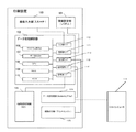
図1は,本発明が適用される印刷装置を示すブロック図である。
Example 1
FIG. 1 is a block diagram showing a printing apparatus to which the present invention is applied.
印刷装置は,スキャナなどの画像入力部100,UIパネルなどの動作環境設部101,ビデオコントローラなどの画像処理部102、HDなどの外部記憶装置103、ネットワークI/FボードやFaxなどの画像送受信部104、プリンタなどの画像出力部105から構成される。上記はホストコンピュータ116と接続するプリンタや、スキャナを備えたコピー、Faxなどが一体となる複合型印刷装置を想定しているが、本発明の構成として全てを要求するものではない。
The printing apparatus includes an
データ処理部102は、入力部I/F110、設定部I/F111、出力部I/F112、送受信I/F113、記憶装置I/F114を備え、内部バスによって、データ処理・制御用プログラムROM106、データROM107、CPU108、内部記憶領域であるRAM109、タイマー(時計機能)115などに接続される。
The
入力データは、スキャナなどの画像入力部100で画像をスキャンしたり、外部ホストコンピュータ、外部Faxやネットワーク経由で送られたプリントデータを送受信部104を介して受信することによりデータ処理部102に取り込まれる。
Input data is taken into the
102に取り込まれたプリントデータは、101で設定された動作環境、または外部からのプリントデータに含まれる動作環境情報に従って処理され、処理後のプリントデータを、目的とする動作に応じて、当該印刷装置で印刷する場合は105、外部ネットワークへプリントデータを送信する場合は104、当該印刷装置内に保存する場合は103へそれぞれ渡される。 The print data captured in 102 is processed according to the operating environment set in 101 or the operating environment information included in the external print data, and the processed print data is printed according to the target operation. When printing is performed by the apparatus, the data is transferred to 105, when the print data is transmitted to the external network, 104, and when stored in the printing apparatus, the data is transferred to 103.
102におけるプリントデータ処理時は、必要に応じてデータROM107の情報などを使用しながら111を経由して取得した処理動作環境に従って、プログラムROM106からプログラムを読み出し、内部記憶領域109などを利用しながら処理を実行する。
When the print data is processed in 102, the program is read from the
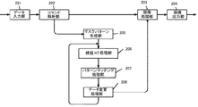
図2は、上記印刷装置において、本発明によるデータ処理を担うコントローラ部の例を示すブロック図である。 FIG. 2 is a block diagram illustrating an example of a controller unit responsible for data processing according to the present invention in the printing apparatus.
印刷データの入力部201で受信したデータコマンドは、コマンド解析部202で解析され、画像データへの変換前処理が行われる。この時、本発明の対象外のコマンドはそのまま画像処理部203へ送られ、画像データに変換された後、画像出力部204へ送られる。
The data command received by the print
コマンド解析部202で前景パターンと背景カラーを指定されたコマンドが検出されると、マスクパターン生成部205にて、マスクパターンに該当する画像データを生成し、さらに模擬HT処理部において、背景カラーを指定した際に得られる中間調処理後のHTパターンを生成する。このHTパターンと205で生成したマスクパターンを比較し、予め規定される背景カラーの顕画素率に満たないと判断された場合は、データ変更処理部208にてデータ変更を行い、変更後のデータを用いて再度206〜207の比較・判定処理を実施する。
When the command specifying the foreground pattern and the background color is detected by the
以上が本発明における基本処理構成となる。 The above is the basic processing configuration in the present invention.
マスクパターンを適用する際、本来であればマスクがなされない画素に対しては元画像の当該画素が持つカラーが再現されることが期待されるが、印刷装置側の条件により擬似中間調処理により本来顕画素となるべき画素を非点灯としているため、条件によって顕画素を増加させる手段を備える必要がある。 When applying a mask pattern, it is expected that the color of the pixel of the original image will be reproduced for pixels that are not masked. Since the pixels that should originally be the visible pixels are not lit, it is necessary to provide means for increasing the visible pixels depending on the conditions.
さらに、顕画素を増加させる手段の適用・非適用の判定基準として、予め何らかの判定条件を印刷装置で備えることが必要となる。 Furthermore, it is necessary to provide some determination conditions in advance in the printing apparatus as determination criteria for application / non-application of the means for increasing the visible pixels.
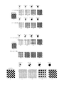
図4−1は、請求項1、2にかかる手段を用いて画像補正を実施した場合の、補正前後の画像データを示す概念図である。 FIG. 4A is a conceptual diagram illustrating image data before and after correction when image correction is performed using the means according to claims 1 and 2.
図4−1においては
・HTパターン中の点灯画素が50%以上の場合は、何らかの色が再現される
を条件とし、前景パターンとして4101に示すマスクパターンが指定された場合、2つの異なるディザパターンを用いて印刷画像を生成した場合を説明する。
In Fig. 4-1. When the number of lit pixels in the HT pattern is 50% or more, if the mask pattern shown in 4101 is specified as the foreground pattern under the condition that some color is reproduced, two different dither patterns A case where a print image is generated using the above will be described.
ディザパターンAは、入力信号レベルがLVL1〜LVL4まで変化すると、4102,4104,4106,4108で示すHTパターンを生成する。 The dither pattern A generates HT patterns indicated by 4102, 4104, 4106, and 4108 when the input signal level changes from LVL1 to LVL4.
また、ディザパターンBは、入力信号レベルがLVL1〜LVL4まで変化すると、4109,4111,4113,4115で示すHTパターンを生成する。 The dither pattern B generates HT patterns indicated by 4109, 4111, 4113, and 4115 when the input signal level changes from LVL1 to LVL4.
マスクパターン4101に対してディザAを適用した場合、LVL1及びLVL2ではマスクパターンのOFF画素とHTパターンのON画素が重なるため、いずれも全く点灯画素が発生しない(4103,4105)。その後、LVL3、LVL4で一定の点灯画素が発生する。 When dither A is applied to the mask pattern 4101, in LVL1 and LVL2, since the OFF pixel of the mask pattern and the ON pixel of the HT pattern overlap each other, no lit pixel is generated at all (4103, 4105). Thereafter, certain lighting pixels are generated in LVL3 and LVL4.
この時、前提条件に従うと、LVL2では何らかの色が再現されなければならないが、本ディザではこれを実現することができない。 At this time, according to the preconditions, some color must be reproduced in LVL2, but this cannot be realized in this dither.
一方、ディザBを適用した場合、LVL1では同じく点灯画素は発生しない(4110)が、LVL2からは点灯画素が発生する(4112,4114,4116)。 On the other hand, when Dither B is applied, a lit pixel is not generated in LVL1 (4110), but a lit pixel is generated from LVL2 (4112, 4114, 4116).
この時、前提条件に従うと、LVL2では何らかの色が再現されなければならないが、本ディザではこれを実現することが可能である。 At this time, according to the preconditions, some color must be reproduced in the LVL2, but this can be realized in the present dither.
したがって、本前景パターンから形成されるマスクパターンに対してはディザBが好ましいと判断する。 Therefore, it is determined that dither B is preferable for the mask pattern formed from the foreground pattern.
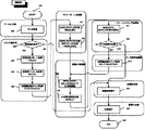
以下、図5を用いて請求項1及び2にかかる実施例を詳細に説明する。 The embodiment according to claims 1 and 2 will be described below in detail with reference to FIG.
データ入力部において、502で印刷データを受信すると、コマンド解析部に移行する。 When the data input unit receives print data in 502, the process proceeds to the command analysis unit.
コマンド解析部では、503で図形描画コマンドであるかどうかを判断し、図形描画でない場合はそのまま画像処理部の514へ移行して通常の画像処理を実行する。
In the command analysis unit, it is determined in step 503 whether the command is a graphic drawing command. If the graphic drawing is not performed, the process proceeds to the
図形描画コマンドと判断された場合は、504で指定の前景パターンを取得し、505で指定の背景カラー(塗り潰し色)を取得する。さらに506で指定背景カラーの中間調処理に適用するディザパターンを取得する。 If it is determined that the drawing command is a graphic drawing command, the designated foreground pattern is obtained at 504 and the designated background color (filled color) is obtained at 505. In step 506, a dither pattern to be applied to the halftone process of the designated background color is acquired.
次にマスクパターン生成部に移り、507でマスクパターンサイズを計算する。このサイズは前景パターンの印字領域全体と等価とする。次に508で前記マスクパターンサイズの図形オブジェクトを生成する。 Next, the process proceeds to the mask pattern generation unit, and the mask pattern size is calculated in 507. This size is equivalent to the entire print area of the foreground pattern. Next, in 508, a graphic object having the mask pattern size is generated.
次に模擬HT処理部に移行し、509では508で生成したマスク図形に対し背景カラーを用いて模擬HT処理を実施する。この時背景カラーは506で指定されたディザパターンを用いて中間調処理を行い、ハーフトーンパターンを生成する。 Next, the process proceeds to a simulated HT processing unit. In 509, simulated HT processing is performed on the mask graphic generated in 508 using the background color. At this time, the background color is subjected to halftone processing using the dither pattern specified in 506 to generate a halftone pattern.
次にパターンマッチング処理部に移行し、511で前景に指定されているマスクパターンと、510で生成したハーフトーンパターンを比較し、511でパターン比較を行う。 Next, the process proceeds to the pattern matching processing unit. The mask pattern designated as the foreground in 511 is compared with the halftone pattern generated in 510, and the pattern is compared in 511.
比較の結果、顕画素条件に鑑みてデータ変更が必要と判断された場合、データ変更処理部へ移行し、513で適用するディザパターンを変更する。その後、再度509へ戻り、模擬HT処理とパターンマッチング処理を実施する。
パターンマッチング処理にて顕画素条件を満たしその後のデータ変更は不要と判断された段階で、画像処理部へ移行し、514で通常の画像処理を実施する。
As a result of the comparison, when it is determined that the data change is necessary in view of the visible pixel condition, the process proceeds to the data change processing unit, and the dither pattern applied in 513 is changed. Thereafter, the process returns to 509 again, and the simulated HT process and the pattern matching process are performed.
When it is determined that the visible pixel condition is satisfied in the pattern matching process and the subsequent data change is unnecessary, the process proceeds to the image processing unit, and normal image processing is performed at 514.
これにより、顕画素条件を満たすディザパターンにより実際の図形コマンドデータが処理されるため、問題の発生を回避する事が可能となる。 As a result, the actual graphic command data is processed by the dither pattern that satisfies the visible pixel condition, so that the occurrence of a problem can be avoided.
(実施例2)
図4−2は、請求項1、3にかかる手段を用いて画像補正を実施した場合の、補正前後の画像データを示す概念図である。
(Example 2)
FIG. 4-2 is a conceptual diagram showing image data before and after correction when image correction is performed using the means according to
図4−2においては
・HTパターン中の点灯画素が全く無い場合以外は、何らかの色が再現される
を条件とし、前景パターンとして4201に示すマスクパターンが指定された場合、2つの異なるディザオフセットを用いて印刷画像を生成した場合を説明する。
In Fig. 4-2-Except when there is no lit pixel in the HT pattern, if the mask pattern shown by 4201 is specified as the foreground pattern under the condition that some color is reproduced, two different dither offsets are set. A case where a print image is generated using the above will be described.
ここで適用するディザは、入力信号レベルがLVL1〜LVL4まで変化すると、4202,4204,4206,4208で示すHTパターンを生成する。 The dither applied here generates an HT pattern indicated by 4202, 4204, 4206, 4208 when the input signal level changes from LVL1 to LVL4.
マスクパターン4201に対してディザオフセットなしを適用した場合、LVL1及びLVL2ではマスクパターンのOFF画素とHTパターンのON画素が重なるため、いずれも全く点灯画素が発生しない(4203,4205)。その後、LVL3、LVL4で一定の点灯画素が発生する。 When no dither offset is applied to the mask pattern 4201, in LVL1 and LVL2, the OFF pixel of the mask pattern and the ON pixel of the HT pattern overlap, so that no lit pixel is generated at all (4203, 4205). Thereafter, certain lighting pixels are generated in LVL3 and LVL4.
この時、前提条件に従うと、LVL1及び2においても何らかの色が再現されなければならないが、本オフセットではこれを実現することができない。 At this time, according to the precondition, some color must be reproduced in LVL1 and LVL2, but this cannot be realized with this offset.
一方、オフセットありを適用した場合、LVL1からLVL4まで全て点灯画素が発生する(4210、4212,4214,4216)。 On the other hand, when “with offset” is applied, all of the lit pixels are generated from LVL1 to LVL4 (4210, 4212, 4214, 4216).
この時、前提条件に従うと、全てのレベルで何らかの色が再現されなければならないが、オフセットではこれを実現することが可能である。 At this time, according to the preconditions, some color must be reproduced at all levels, but this can be achieved with an offset.
したがって、本前景パターンから形成されるマスクパターンに対してはディザオフセットありが好ましいと判断する。 Therefore, it is determined that a dither offset is preferable for the mask pattern formed from the foreground pattern.
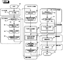
以下、図6を用いて請求項1及び3にかかる実施例を詳細に説明する。
The embodiment according to
データ入力部において、602で印刷データを受信すると、コマンド解析部に移行する。 In the data input unit, when print data is received in 602, the process proceeds to the command analysis unit.
コマンド解析部では、603で図形描画コマンドであるかどうかを判断し、図形描画でない場合はそのまま画像処理部の616へ移行して通常の画像処理を実行する。 In the command analysis unit, it is determined in step 603 whether the command is a graphic drawing command. If the graphic drawing command is not used, the process proceeds to the image processing unit 616 as it is and normal image processing is executed.
図形描画コマンドと判断された場合は、604で指定の前景パターンを取得し、605で指定の背景カラー(塗り潰し色)を取得する。さらに606で指定背景カラーの中間調処理に適用するディザパターンを取得する。 If it is determined that the drawing command is a graphic drawing command, a designated foreground pattern is obtained at 604 and a designated background color (filled color) is obtained at 605. In step 606, a dither pattern to be applied to the halftone process of the designated background color is acquired.
次にマスクパターン生成部に移り、607でマスクパターンサイズを計算する。このサイズは前景パターンの印字領域全体と等価とする。次に608で前記マスクパターンサイズの図形オブジェクトを生成する。 Next, the process proceeds to a mask pattern generation unit, and a mask pattern size is calculated in 607. This size is equivalent to the entire print area of the foreground pattern. In step 608, a graphic object having the mask pattern size is generated.
次に模擬HT処理部に移行し、609でディザオフセットを初期化する。次に610でディザオフセットを所定の値(現時点では初期化されているのでオフセットなし)に設定する。 Next, the process proceeds to the simulated HT processing unit, and a dither offset is initialized at 609. Next, at 610, the dither offset is set to a predetermined value (no offset because it is initialized at the present time).
次に611では608で生成したマスク図形に対し背景カラーを用いて模擬HT処理を実施する。この時背景カラーは606で指定されたディザパターンを用いて中間調処理を行い、ハーフトーンパターンを生成する。 Next, in 611, a simulated HT process is performed on the mask figure generated in 608 using the background color. At this time, the background color is subjected to halftone processing using the dither pattern specified in 606 to generate a halftone pattern.
次にパターンマッチング処理部に移行し、613で前景に指定されているマスクパターンと、612で生成したハーフトーンパターンを比較し、614でパターン比較を行う。 Next, the process proceeds to the pattern matching processing unit, where the mask pattern designated as the foreground at 613 is compared with the halftone pattern generated at 612, and pattern comparison is performed at 614.
比較の結果、顕画素条件に鑑みてデータ変更が必要と判断された場合、データ変更処理部へ移行し、615で適用するディザオフセット値を変更する。その後、再度610へ戻り、模擬HT処理とパターンマッチング処理を実施する。 As a result of the comparison, when it is determined that the data change is necessary in view of the visible pixel condition, the process proceeds to the data change processing unit, and the dither offset value applied in 615 is changed. Thereafter, the process returns to 610 again, and the simulated HT process and the pattern matching process are performed.
パターンマッチング処理にて顕画素条件を満たしその後のデータ変更は不要と判断された段階で、画像処理部へ移行し、616で通常の画像処理を実施する。 When it is determined that the visible pixel condition is satisfied in the pattern matching process and the subsequent data change is unnecessary, the process proceeds to the image processing unit, and normal image processing is performed in 616.
これにより、顕画素条件を満たすディザパターンにより実際の図形コマンドデータが処理されるため、問題の発生を回避する事が可能となる。 As a result, the actual graphic command data is processed by the dither pattern that satisfies the visible pixel condition, so that the occurrence of a problem can be avoided.
(実施例3)
図4−3は、請求項1、4にかかる手段を用いて画像補正を実施した場合の、補正前後の画像データを示す概念図である。
(Example 3)
FIG. 4-3 is a conceptual diagram illustrating image data before and after correction when image correction is performed using the means according to claims 1 and 4.
図4−3においては
・HTパターン中の点灯画素が全く無い場合以外は、何らかの色が再現される
を条件とし、前景パターンとして4301に示すマスクパターンが指定された場合、入力信号レベルに対する印刷画像を説明する。
In Fig. 4-3: Unless the HT pattern has no lit pixels at all, if some color is reproduced, and the mask pattern shown by 4301 is specified as the foreground pattern, the printed image for the input signal level Will be explained.
ここで適用するディザは、入力信号レベルがLVL1〜LVL4まで変化すると、4302,4304,4306,4308で示すHTパターンを生成する。 The dither applied here generates HT patterns indicated by 4302, 4304, 4306, and 4308 when the input signal level changes from LVL1 to LVL4.
マスクパターン4301に対して、LVL1及びLVL2ではマスクパターンのOFF画素とHTパターンのON画素が重なるため、いずれも全く点灯画素が発生しない(4303,4305)。その後、LVL3、LVL4で一定の点灯画素が発生する。 With respect to the mask pattern 4301, in LVL1 and LVL2, the OFF pixel of the mask pattern and the ON pixel of the HT pattern overlap with each other, so that no lit pixel is generated at all (4303, 4305). Thereafter, certain lighting pixels are generated in LVL3 and LVL4.
この時、前提条件に従うと、LVL1及び2においても何らかの色が再現されなければならないが、このままではこれを実現することができない。 At this time, according to the precondition, some color must be reproduced in the LVLs 1 and 2, but this cannot be realized as it is.
前提条件に従うためには、元画像の当該画素に対するディザへの入力信号がLVL1またはLVL2の場合、実際の入力レベルをLVL3に変換すれば上記を実現することが可能となる。 In order to comply with the precondition, when the input signal to the dither for the pixel of the original image is LVL1 or LVL2, the above can be realized by converting the actual input level to LVL3.
したがって、本前景パターンから形成されるマスクパターンに対してはディザへの入力信号を元信号から+2することが好ましいと判断する。 Therefore, it is determined that the input signal to the dither is preferably +2 from the original signal for the mask pattern formed from this foreground pattern.
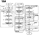
以下、図7を用いて請求項1及び4にかかる実施例を詳細に説明する。 The embodiment according to claims 1 and 4 will be described in detail below with reference to FIG.
データ入力部において、702で印刷データを受信すると、コマンド解析部に移行する。 In the data input unit, when print data is received in 702, the process proceeds to the command analysis unit.
コマンド解析部では、703で図形描画コマンドであるかどうかを判断し、図形描画でない場合はそのまま画像処理部の715へ移行して通常の画像処理を実行する。
図形描画コマンドと判断された場合は、704で指定の前景パターンを取得し、705で指定の背景カラー(塗り潰し色)を取得する。さらに706で指定背景カラーの中間調処理に適用するディザパターンを取得する。
The command analysis unit determines whether the command is a graphic drawing command in 703. If the command is not graphic drawing, the process proceeds to 715 of the image processing unit as it is and normal image processing is executed.
If it is determined that the drawing command is a graphic drawing command, the designated foreground pattern is obtained at 704 and the designated background color (filled color) is obtained at 705. In step 706, a dither pattern to be applied to the halftone process of the designated background color is acquired.
次にマスクパターン生成部に移り、707でマスクパターンサイズを計算する。このサイズは前景パターンの印字領域全体と等価とする。次に708で前記マスクパターンサイズの図形オブジェクトを生成する。 Next, the process proceeds to a mask pattern generation unit, and a mask pattern size is calculated in 707. This size is equivalent to the entire print area of the foreground pattern. Next, in 708, a graphic object having the mask pattern size is generated.
次に模擬HT処理部に移行し、709で背景カラー信号からディザへの入力信号を計算する。 Next, the process proceeds to the simulated HT processing unit, and in 709, an input signal from the background color signal to the dither is calculated.
次に710では708で生成したマスク図形に対し709で計算したディザへの入力信号を用いて模擬HT処理を実施する。この時背景カラーは709で計算された入力信号を706で指定されたディザパターンへ適用することで中間調処理を行い、ハーフトーンパターンを生成する。 Next, at 710, the simulated HT process is performed on the mask figure generated at 708 using the input signal to the dither calculated at 709. At this time, the background color is subjected to halftone processing by applying the input signal calculated in 709 to the dither pattern specified in 706 to generate a halftone pattern.
次にパターンマッチング処理部に移行し、712で前景に指定されているマスクパターンと、711で生成したハーフトーンパターンを比較し、713でパターン比較を行う。 Next, the process proceeds to the pattern matching processing unit, where the mask pattern designated as the foreground at 712 is compared with the halftone pattern generated at 711, and pattern comparison is performed at 713.
比較の結果、顕画素条件に鑑みてデータ変更が必要と判断された場合、データ変更処理部へ移行し、714で適用するディザへの入力信号値を変更する。その後、再度710へ戻り、模擬HT処理とパターンマッチング処理を実施する。
パターンマッチング処理にて顕画素条件を満たしその後のデータ変更は不要と判断された段階で、画像処理部へ移行し、715で通常の画像処理を実施する。
As a result of the comparison, when it is determined that the data change is necessary in view of the visible pixel condition, the process proceeds to the data change processing unit, and the input signal value to the dither applied in 714 is changed. Thereafter, the process returns to 710 again, and the simulated HT process and the pattern matching process are performed.
When it is determined that the visible pixel condition is satisfied in the pattern matching process and the subsequent data change is unnecessary, the process proceeds to the image processing unit, and normal image processing is performed in 715.
これにより、顕画素条件を満たすディザパターンにより実際の図形コマンドデータが処理されるため、問題の発生を回避する事が可能となる。 As a result, the actual graphic command data is processed by the dither pattern that satisfies the visible pixel condition, so that the occurrence of a problem can be avoided.
Claims (4)
Priority Applications (1)
| Application Number | Priority Date | Filing Date | Title |
|---|---|---|---|
| JP2004358294A JP2006166328A (en) | 2004-12-10 | 2004-12-10 | Image processing device |
Applications Claiming Priority (1)
| Application Number | Priority Date | Filing Date | Title |
|---|---|---|---|
| JP2004358294A JP2006166328A (en) | 2004-12-10 | 2004-12-10 | Image processing device |
Publications (1)
| Publication Number | Publication Date |
|---|---|
| JP2006166328A true JP2006166328A (en) | 2006-06-22 |
Family
ID=36667786
Family Applications (1)
| Application Number | Title | Priority Date | Filing Date |
|---|---|---|---|
| JP2004358294A Withdrawn JP2006166328A (en) | 2004-12-10 | 2004-12-10 | Image processing device |
Country Status (1)
| Country | Link |
|---|---|
| JP (1) | JP2006166328A (en) |
Cited By (1)
| Publication number | Priority date | Publication date | Assignee | Title |
|---|---|---|---|---|
| JP2012156959A (en) * | 2011-01-28 | 2012-08-16 | Kyocera Document Solutions Inc | Image forming device and image forming program |
-
2004
- 2004-12-10 JP JP2004358294A patent/JP2006166328A/en not_active Withdrawn
Cited By (1)
| Publication number | Priority date | Publication date | Assignee | Title |
|---|---|---|---|---|
| JP2012156959A (en) * | 2011-01-28 | 2012-08-16 | Kyocera Document Solutions Inc | Image forming device and image forming program |
Similar Documents
| Publication | Publication Date | Title |
|---|---|---|
| JP5640685B2 (en) | Image output inspection system, image inspection apparatus, and program | |
| EP0781034B1 (en) | Image processing apparatus and method | |
| EP0772347A2 (en) | Colour printing using a dither cell | |
| US8159694B2 (en) | Image processor and image processing method processing an image that includes a semi-transparent object or an image with periodically varying density | |
| US6288795B1 (en) | Method and apparatus for converting continuous-tone images to bi-level images | |
| JP2005354231A (en) | Image processing apparatus, image processing method, image processing program, and storage medium | |
| US20030063144A1 (en) | Image processing apparatus and method and recording medium | |
| JPH10112801A (en) | Input image processing method | |
| JPH1084478A (en) | Input image conversion method and pixel value quantization method | |
| JPH08195886A (en) | Generating method for adjusted dither matrix | |
| JP6613115B2 (en) | Image processing apparatus, image processing method, and program | |
| US10674037B2 (en) | Image processing apparatus, image processing method, and storage medium with halftone processing using dither matrix of dot concentration type or dither matrix of dot distribution type | |
| JP4783566B2 (en) | System and method for processing color image data | |
| JP2000255110A (en) | Color print system and control method thereof | |
| EP1734737B1 (en) | Image processing method and a recording medium storing image processing program | |
| JP2005182824A (en) | Method for processing image data | |
| JP2002016814A5 (en) | ||
| JP2006166328A (en) | Image processing device | |
| US7187387B2 (en) | Image processing apparatus capable of creating a dither matrix providing improved image quality | |
| JPH0738767A (en) | Image binarization processor | |
| EP0786895B1 (en) | Image processing system and method | |
| JP2002225381A (en) | Image processor and image processing method | |
| US20060092439A1 (en) | Printer controller, image forming apparatus, image forming program | |
| JP4525916B2 (en) | Image forming apparatus, image forming method, image processing apparatus, and image processing method | |
| JP2001018455A (en) | Processing device for gradation image |
Legal Events
| Date | Code | Title | Description |
|---|---|---|---|
| A300 | Withdrawal of application because of no request for examination |
Free format text: JAPANESE INTERMEDIATE CODE: A300 Effective date: 20080304 |