JP2006155407A - Charge collection terminal equipment - Google Patents
Charge collection terminal equipment Download PDFInfo
- Publication number
- JP2006155407A JP2006155407A JP2004347593A JP2004347593A JP2006155407A JP 2006155407 A JP2006155407 A JP 2006155407A JP 2004347593 A JP2004347593 A JP 2004347593A JP 2004347593 A JP2004347593 A JP 2004347593A JP 2006155407 A JP2006155407 A JP 2006155407A
- Authority
- JP
- Japan
- Prior art keywords
- housing
- collection terminal
- casing
- upper housing
- terminal device
- Prior art date
- Legal status (The legal status is an assumption and is not a legal conclusion. Google has not performed a legal analysis and makes no representation as to the accuracy of the status listed.)
- Pending
Links
Images


Landscapes
- Devices For Checking Fares Or Tickets At Control Points (AREA)
Abstract
Description
本発明は、高速道路などの有料道路に設置される有料道路料金収受システムの料金収受端末装置に関する。 The present invention relates to a toll collection terminal device of a toll road toll collection system installed on a toll road such as an expressway.
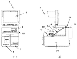
図5に有料道路に設置される有料道路料金収受システムの料金収受端末装置100を示す。この料金収受端末装置100は、出口車線の料金所ブース内に設けられた机などの設置卓130の上に設置、運用される(図5(1)参照)。
FIG. 5 shows a toll
料金収受端末装置100は、カード処理部107、領収書発行部106など比較的重量のあるユニットを下部筐体120に収納し、主制御部104、操作部102、表示部103、電源105などが上部筐体110に収納されている(例えば、特許文献1参照。)。料金所ブースは車線と車線の間に設けられるため、設置スペースが限られており、料金収受端末装置の背面を含む周囲に余分な空間が設けられていない。操作員は、この料金所ブース内から料金収受端末装置100を操作して車両の利用者との間で料金の収受業務を行う。従って、料金収受端末装置100の保守時には、電気的調整・確認などを行うため、料金収受端末装置100内部に配置された主制御部104にアクセスする必要があり、この際には上部筐体110を開く必要がある。
The toll
図5(1)〜図5(3)を参照して料金収受端末装置100の上部筐体110を開く場合の操作を説明する。図5(1)は、設置卓130の上に料金所ブース壁140に接近した状態で料金収受端末装置100が設置されている状態で、通常の利用形態である。
An operation for opening the
図5(2)は、保守のために料金収受端末装置100の内部にアクセスするため、表示部103を折りたたみ、さらに料金収受端末装置100を手前に引き出した状態を示す図である。このように、料金収受端末装置100を図示矢印で示すように手前に引き出す必要があるのは、上部筐体110を開いたとき、上部筐体110の後部が料金所ブース壁140に接触して開かないため、事前に上部筐体110の高さに相当する距離だけ手前に引き出す必要がある。料金所ブースが狭く、設置卓の奥行きが短いと図示したように料金収受端末装置100が設置卓からはみ出して安全性が損なわれる場合があり問題となっていた。
FIG. 5B is a diagram showing a state in which the
図5(3)は、料金収受端末装置100の内部にアクセスするために、上部筐体110を開いた状態を示す図である。
FIG. 5 (3) is a diagram showing a state in which the
このように構成された料金収受端末装置の保守を行う場合のために、従来の料金収受端末装置には、下部筐体に収納されている両方のユニットを同時に引き出すと重心が手前に大きく移動して安全性を損なうため、何れか一方のユニットのみ手前に引き出せる方法が知られている(例えば、特許文献1参照。)。
しかしながら、特許文献1記載の料金収受端末装置は、上部筐体と下部筐体の略中央部を上下に水平分割して、かつ、筺体の上部が筺体の略中央の背面側に設けられた回動可能なヒンジ108を軸として回動するため、上部筐体を開く際に上部筐体が背面側にせり出す形(上部筐体の突出)になる(図5(3)参照)。筺体の背面を奥の壁に接した状態で設置した場合は、背面の壁にぶつかり開くことができないため、料金収受端末装置内部にアクセスできないという問題があった。このため、従来から、料金収受端末装置内部にアクセスする際には、まず料金収受端末装置全体を手前に引き出す作業を行っていた(図5(2)参照)。しかし、料金収受端末装置の質量が45kg程度になることから。手前に引き出す作業がスムーズな保守作業の妨げになるという問題があった。
However, the toll collection terminal device described in
さらに、手前に引き出すと料金収受端末装置が設置卓から手前側に突出する形となり、保守時の安全性が損なわれるという問題があった。 Furthermore, when it is pulled out to the front, the toll collection terminal device protrudes from the installation table to the front side, and there is a problem that safety during maintenance is impaired.
本発明は、上記問題を解決するためになされたもので、料金収受端末装置の筐体分割において、上部筐体の上面位置に回動可能なヒンジを設け、上部筐体を分割回動することにすることによって、料金収受端末装置を手前に引き出さなくとも上部筐体を開くことができるため、保守性及び安全性にすぐれた料金収受端末装置を提供する。 The present invention has been made to solve the above-described problem. In the case of dividing the toll collection terminal device, a rotatable hinge is provided at the upper surface of the upper case, and the upper case is divided and rotated. By doing so, the upper housing can be opened without pulling out the toll collection terminal device, so that a toll collection terminal device having excellent maintainability and safety is provided.
上記目的を達成するために、本発明の請求項1記載の料金収受端末装置は、L字状の箱体をなす下部筐体と、この下部筐体の箱体を構成する側板に接して配置されたカバーからなる上部筐体と、前記上部筐体の背面側上部と、固定配置される前記下部筐体の天板とが接する線上を回動軸として、前記上部筐体を前記下部筐体に回動可能に連結する連結部材と、前記上部筐体を回動したとき所定の位置で停止させるためのストッパーとを備え、前記上部筐体は、前記軸から垂直方向に当該上部筐体の最も高い位置までの第1の長さが、この軸から水平方向に前記下部筐体の背面までの第2の長さ以下になるように構成したことを特徴とする。
In order to achieve the above object, a toll collection terminal device according to
本発明によれば、料金収受端末装置の筐体分割において、料金収受端末装置の筐体上面の連結部材によって分割することができるため、料金収受端末装置を手前に引き出さなくとも上部筐体を開くことができるため、保守性及び安全性にすぐれた料金収受端末装置を提供することができる。 According to the present invention, the housing of the toll collection terminal device can be divided by the connecting member on the upper surface of the housing of the toll collection terminal device, so that the upper housing can be opened without pulling out the toll collection terminal device. Therefore, it is possible to provide a toll collection terminal device excellent in maintainability and safety.
以下、図面を参照して本発明の実施例を説明する。 Embodiments of the present invention will be described below with reference to the drawings.
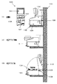
図1は、本発明の実施例1による料金収受端末装置(以下、装置と称する。)1の外観図である。図1(1)は操作側から見た正面図で、図1(2)は右側面図である。この装置1は、上部筐体10と下部筐体20で構成されている。
FIG. 1 is an external view of a toll collection terminal device (hereinafter referred to as a device) 1 according to a first embodiment of the present invention. FIG. 1 (1) is a front view seen from the operation side, and FIG. 1 (2) is a right side view. The
上部筺体には操作部2、表示部3が設けられており、下部筐体20には主制御部4、電源部5、領収書発行部6、カード処理部7、が設けられている。
An
操作部2には、操作員が料金収受の際に操作するキーボードが配置されている。表示部3には、料金収受に伴う車種情報、利用料金、障害などが表示される。主制御部4は、装置全体を制御するCPUを有する制御基板で構成され、下部筐体10に内蔵されている。電源部5は、装置1が稼動するために必要な電源を供給する。領収書発行部6は、プリンタを有し領収書を発行する。カード処理部7は、プリペードカード挿入/排出口を有し、プリペードカードから利用料金の収受を行う。
The
下部筐体20と上部筐体10の分割ラインは、装置の前面側では筺体上下の略中央を上下に水平分割し、装置の後部ではこの水平分割ラインに対して上側に垂直となる垂直分割ラインによるL字型分割となる。したがって、下部筐体20は、L字状の箱体を形成し、上部筐体10は、下部筐体20の箱体を形成する側板に接して配置されたカバーを形成する。上記垂直分割ラインが上部筐体10天板(当該装置1筐体上面)と接する線上(境部)を回動軸として上部筐体10を回動可能に下部筐体20に連結するヒンジなどの連結部材8が設けられている。
The dividing line of the
また、上部筐体10を回動したとき、所定の位置で止めるためのストッパー9が設けられている。そのため、操作員はこの連結部材8を支点として上部筐体10が停止するまで回動させることができる。
A
図2は、本発明の実施例による装置1の筐体分割ライン30を説明する図である。図2(1)は操作側から見た正面図で、図2(2)は、右側面図である。
FIG. 2 is a diagram illustrating the housing dividing
筺体分割ライン30は、下部筐体20の天板と上部筐体10の底部を分割する水平分割ライン30Aと、この水平分割ライン30Aの後部に、所定の奥行きD2を残して水平分割ライン30Aに対してL字になるように上に向かって垂直に設けられた垂直分割ライン30Bからなる。すなわちL字型分割ラインを形成する。
The
この垂直分割ライン30Bの上部終端は、分割された上部筐体10と下部筐体20をヒンジなどの回動可能な連結部材8で連結される。この際、軸から垂直方向に上部筐体10の最も高い位置までの長さ(第1の長さ)D1は、軸から水平方向に下部筐体20の背面までの長さ(第2の長さ)D2以下になるように構成されている必要がある。すなわち、下式(1)を満たす必要がある。
D1≦D2・・・・・・(1)
D1:軸から垂直方向に上部筐体10の最も高い位置までの長さ(第1の長さ)
D2:軸から水平方向に下部筐体20の背面までの長さ(第2の長さ)
以上の条件を満たす連結によって、上部筐体10が連結部材8を軸として所定の位置で停止するまで回動する(開く)ことができる。以上の条件を満たさない場合、上部筐体10を回動すると、上部筐体10の天板部分が下部筐体20の背面より後ろ側に突出する場合がある。
The upper end of the vertical dividing
D1 ≦ D2 (1)
D1: Length from the axis to the highest position of the
D2: Length from the axis to the back surface of the
By the connection satisfying the above conditions, the
ストッパー9は、上部筐体10を所定の位置で停止するまで持ち上げて回動した後(開ききった後)、手前に戻すと自動ロックが働き、自然落下を防止する。この自動ロック状態になると、上部筐体10は止まっており、持ち上げた手を離しても落下することがなく、例えば主制御部4にアクセスし、電気調整・確認などを行うことができる。
The
上述した上部筐体10が自動ロックした状態を解除するには、ストッパー9に設けられたロック解除スイッチ9Aを押した後、上部筐体10を所定の停止位置まで持ち上げて回動した後(再度、開ききった後)、手前に倒すと閉じることが可能になる。すなわち、ロック解除スイッチ9Aを押下することにより所定の位置で停止している前記上部筐体10を元の位置に戻すことができる。
In order to release the above-described state in which the
図3は、保守時など、装置1の上部筐体10を持ち上げて装置1の内部にアクセスする場合の操作を示す図である。図3(1)は、料金所ブース壁40に接近して設置卓30の上に装置1が設置されている状態で、通常の利用形態である。
FIG. 3 is a diagram illustrating an operation when the
図3(2)は、保守のために装置1の内部にアクセスするため、表示部3を折りたたんだ状態を示す図である。
FIG. 3B is a diagram illustrating a state in which the
図3(3)は、装置1の内部にアクセスするために、上部筐体10を回動し、ストッパー9によって自動ロックして停止した状態(上部筐体10が開いた状態)を示す図である。上部筐体10を開くことによって、主制御部4が露出し、必要な保守作業を行うことができる。本実施例1では、従来の装置のように上部筐体10を開く際に装置1を手前に引き出す操作をしなくとも下部筐体20内部にアクセス可能なため保守性及び安全性に優れた装置になる。
FIG. 3 (3) is a diagram showing a state where the
図4は、本発明の実施例2による料金収受端末装置(以下、装置と称する。)1の外観図である。図4(1)は操作側から見た正面図で、図4(2)は右側面図である。この装置1は、上部筐体10と下部筐体20で構成されており、分割ライン30Cが異なっているが、その他の部分は実施例1と同じであるため、同一部分には同一符号を付けてその説明を省略する。
FIG. 4 is an external view of a toll collection terminal device (hereinafter referred to as device) 1 according to the second embodiment of the present invention. FIG. 4A is a front view seen from the operation side, and FIG. 4B is a right side view. This
本実施例2では、上部筐体10と下部筐体20を分割する分割ライン30Cが上部筐体10の下部から装置1の筐体上面に向かって斜めに設けられている。
In the second embodiment, a
上記実施例1では、筐体分割ラインを上下に水平分割し、かつ、これと垂直な垂直分割になっており、これについて説明したが、これに限定されることなく本実施例2のように装置1の筐体上面に上部筐体10と下部筐20との回動軸を設ける構成にすることにより、実施例1同様の効果を奏することができる。
In the first embodiment, the case dividing line is horizontally divided up and down, and the vertical division is perpendicular to the case dividing line. However, the present invention is not limited to this, as in the second embodiment. By adopting a configuration in which the rotation shafts of the
1 料金収受端末装置
2 操作部
3 表示部
4 主制御部
5 電源部
6 領収書発行部
7 カード処理部
8 連結部材
9 ストッパー
9A ロック解除スイッチ
10 上部筐体
20 下部筐体
30 筐体分割ライン
30A 水平分割ライン
30B 垂直分割ライン
DESCRIPTION OF
Claims (3)
この下部筐体の箱体を構成する側板に接して配置されたカバーからなる上部筐体と、
前記上部筐体の背面側上部と、固定配置される前記下部筐体の天板とが接する線上を回動軸として、前記上部筐体を前記下部筐体に回動可能に連結する連結部材と、
前記上部筐体を回動したとき所定の位置で停止させるためのストッパーと
を備え、前記上部筐体は、前記軸から垂直方向に当該上部筐体の最も高い位置までの第1の長さが、この軸から水平方向に前記下部筐体の背面までの第2の長さ以下になるように構成したことを特徴とする料金収受端末装置。 A lower housing forming an L-shaped box,
An upper housing comprising a cover disposed in contact with a side plate constituting the box of the lower housing;
A connecting member that pivotally connects the upper casing to the lower casing, with a line on the upper surface on the back side of the upper casing and a top plate of the lower casing fixedly arranged as a rotation axis. ,
A stopper for stopping the upper housing at a predetermined position when the upper housing is rotated, and the upper housing has a first length from the axis to the highest position of the upper housing in the vertical direction. A toll collection terminal device configured to be equal to or shorter than a second length from the axis to the back surface of the lower housing in the horizontal direction.
前記上部筐体を当該連結部材を軸にして所定の位置まで持ち上げて回動した後、手前に戻すと回動を停止する自動ロック機能と、
この自動ロック機能によって自動ロックされた状態を解除するロック解除スイッチと
を備え、操作員が前記上部筐体を所定の位置まで回動して停止することにより自然落下を防止し、かつ、前記ロック解除スイッチを押下することにより所定の位置で停止している前記上部筐体を元の位置に戻せるようにしたことを特徴とする請求項1記載の料金収受端末装置。 The stopper is
After the upper housing is turned up to a predetermined position with the connecting member as an axis and turned, and then returned to the front, an automatic lock function that stops turning,
A lock release switch for releasing the state of being automatically locked by the automatic lock function, and an operator rotates the upper housing to a predetermined position to stop it, thereby preventing a natural fall, and the lock 2. The toll collection terminal device according to claim 1, wherein the upper casing stopped at a predetermined position can be returned to its original position by pressing a release switch.
調整、保守時に調整、保守を必要とする制御部が分割配置され、背面側上部が当該装置筐体の上面で前記上部筐体と境部をなす下部筐体と、
当該装置筐体の上面の前記境部を回動軸とし、前記上部筐体を前記下部筐体に対して回動可能に連結する連結部材と
を備えたことを特徴とする料金収受端末装置。 An upper housing in which a display unit for performing toll collection work with users is divided and arranged;
A control unit that requires adjustment and maintenance at the time of adjustment and maintenance is dividedly arranged, and a lower case whose upper side on the back side forms a boundary with the upper case on the upper surface of the device case;
A toll collection terminal device comprising: a connecting member that rotatably connects the upper housing to the lower housing, with the boundary portion of the upper surface of the device housing as a rotation axis.
Priority Applications (1)
| Application Number | Priority Date | Filing Date | Title |
|---|---|---|---|
| JP2004347593A JP2006155407A (en) | 2004-11-30 | 2004-11-30 | Charge collection terminal equipment |
Applications Claiming Priority (1)
| Application Number | Priority Date | Filing Date | Title |
|---|---|---|---|
| JP2004347593A JP2006155407A (en) | 2004-11-30 | 2004-11-30 | Charge collection terminal equipment |
Publications (1)
| Publication Number | Publication Date |
|---|---|
| JP2006155407A true JP2006155407A (en) | 2006-06-15 |
Family
ID=36633599
Family Applications (1)
| Application Number | Title | Priority Date | Filing Date |
|---|---|---|---|
| JP2004347593A Pending JP2006155407A (en) | 2004-11-30 | 2004-11-30 | Charge collection terminal equipment |
Country Status (1)
| Country | Link |
|---|---|
| JP (1) | JP2006155407A (en) |
Citations (4)
| Publication number | Priority date | Publication date | Assignee | Title |
|---|---|---|---|---|
| JPH02143482U (en) * | 1989-05-01 | 1990-12-05 | ||
| JPH0512972U (en) * | 1991-07-31 | 1993-02-19 | 三菱重工業株式会社 | Terminals for toll roads |
| JPH08153265A (en) * | 1994-11-29 | 1996-06-11 | Fujitsu Ltd | Device with door drop preventing mechanism |
| JPH09115008A (en) * | 1995-10-18 | 1997-05-02 | Kubota Corp | Terminal equipment with display |
-
2004
- 2004-11-30 JP JP2004347593A patent/JP2006155407A/en active Pending
Patent Citations (4)
| Publication number | Priority date | Publication date | Assignee | Title |
|---|---|---|---|---|
| JPH02143482U (en) * | 1989-05-01 | 1990-12-05 | ||
| JPH0512972U (en) * | 1991-07-31 | 1993-02-19 | 三菱重工業株式会社 | Terminals for toll roads |
| JPH08153265A (en) * | 1994-11-29 | 1996-06-11 | Fujitsu Ltd | Device with door drop preventing mechanism |
| JPH09115008A (en) * | 1995-10-18 | 1997-05-02 | Kubota Corp | Terminal equipment with display |
Similar Documents
| Publication | Publication Date | Title |
|---|---|---|
| EP0571158A1 (en) | Information processing system with printer | |
| JP2005261933A (en) | Game machine | |
| CN1318801A (en) | Computer with modular removable media drive | |
| CN215494921U (en) | Physical heat dissipation device for case of system computer | |
| CN200987185Y (en) | Sliding type semibuilt-in screen type mobile terminal | |
| JP5910925B2 (en) | Image forming apparatus | |
| US7457124B2 (en) | Electronic apparatus | |
| CN101114110B (en) | Lens cap device | |
| JP2006155407A (en) | Charge collection terminal equipment | |
| JP2008003936A (en) | Parking management system | |
| AU2003203217B2 (en) | System and Method for Combining Low-power Signals and High-power Signals on a Single Circuit Board in a Gaming Machine | |
| JP3779578B2 (en) | Amusement stand | |
| JPH0999160A (en) | Shooting ball game machine | |
| CN200993752Y (en) | Computer case panel with protection device | |
| JP2601301Y2 (en) | Electronics | |
| CN211237038U (en) | Self-service terminal equipment with peep-proof cover | |
| CN110039785A (en) | A kind of automatic safe pick-off unit for planer-type 3D printer | |
| CN212052003U (en) | Detergent feeding module for washing machine and washing machine | |
| CN220681987U (en) | Rotatable display screen for printer | |
| CN209231988U (en) | A kind of band Car license recognition Portable bridge charger | |
| CN212546376U (en) | Cabinet is sold to small-size export electron cigarette | |
| JP2001094272A (en) | Electric equipment | |
| JP2006338280A (en) | Automatic vending machine | |
| JPH09115008A (en) | Terminal equipment with display | |
| CN1160607C (en) | Fixing mechanism for data access device |
Legal Events
| Date | Code | Title | Description |
|---|---|---|---|
| A621 | Written request for application examination |
Free format text: JAPANESE INTERMEDIATE CODE: A621 Effective date: 20071003 |
|
| A977 | Report on retrieval |
Free format text: JAPANESE INTERMEDIATE CODE: A971007 Effective date: 20100805 |
|
| A131 | Notification of reasons for refusal |
Free format text: JAPANESE INTERMEDIATE CODE: A131 Effective date: 20100810 |
|
| A02 | Decision of refusal |
Free format text: JAPANESE INTERMEDIATE CODE: A02 Effective date: 20101203 |