JP2006148977A - Fm signal optical receiver - Google Patents
Fm signal optical receiver Download PDFInfo
- Publication number
- JP2006148977A JP2006148977A JP2006035826A JP2006035826A JP2006148977A JP 2006148977 A JP2006148977 A JP 2006148977A JP 2006035826 A JP2006035826 A JP 2006035826A JP 2006035826 A JP2006035826 A JP 2006035826A JP 2006148977 A JP2006148977 A JP 2006148977A
- Authority
- JP
- Japan
- Prior art keywords
- signal
- optical
- frequency
- optical fiber
- modulation
- Prior art date
- Legal status (The legal status is an assumption and is not a legal conclusion. Google has not performed a legal analysis and makes no representation as to the accuracy of the status listed.)
- Pending
Links
Images


Abstract
Description
本発明は、例えば、光通信やCATV、光計測、移動体通信等に用いられるFM信号光受信装置に関する。 The present invention relates to an FM signal light receiving apparatus used for optical communication, CATV, optical measurement, mobile communication, and the like.
近年、映像監視システム,CATV,加入者系,移動体通信等においては、光ファイバの低損失、広帯域特性を活かして、多チャンネルの映像や音声あるいはデータの光伝送を行うことが実用化されている。このような光伝送装置においては、多チャンネルの信号を各々周波数の異なる複数のサブキャリア(副搬送波)によって電気的に多重化してAM信号としたうえで、このAM信号によって半導体レーザ等を直接変調して光信号に変換し光ファイバで伝送している。AM信号の光伝送は、特に映像信号の伝送において変復調器の構成が簡単で低コストとなるという特徴がある。 In recent years, in video surveillance systems, CATV, subscriber systems, mobile communications, etc., it has been put into practical use that optical transmission of multi-channel video, audio, or data is made utilizing the low loss and wideband characteristics of optical fibers. Yes. In such an optical transmission device, a multi-channel signal is electrically multiplexed by a plurality of subcarriers (subcarriers) each having a different frequency to form an AM signal, and a semiconductor laser or the like is directly modulated by the AM signal. Then, it is converted into an optical signal and transmitted through an optical fiber. The optical transmission of AM signals is characterized in that the modulator / demodulator is simple and low-cost especially in the transmission of video signals.
しかしながら、このような光伝送装置では次のような不都合があった。すなわち、映像光伝送においては、所望の信号特性(映像品質等)を確保するためには十分なるC/N(キャリア対雑音比)を確保する必要があるが、AM信号の映像光伝送において、高いC/Nを得るためには受信器側で高い光入力パワーがどうしても必要となる。 However, such an optical transmission device has the following disadvantages. That is, in video optical transmission, it is necessary to ensure a sufficient C / N (carrier-to-noise ratio) to ensure desired signal characteristics (video quality, etc.). In order to obtain a high C / N, high optical input power is absolutely necessary on the receiver side.
また、移動体通信においては、伝送する音声やデータ信号の強度レベルが端末の移動によって大きく変動するため、信号変動に対する高いダイナミックレンジが必要となる。さらに、半導体レーザでの光変換時や光ファイバ伝送途中の反射波によって生じる歪みの影響を受けやすい。さらにまた、AM信号の増幅器にも直線性の良好な増幅器が必要になる。 Also, in mobile communication, the intensity level of voice and data signals to be transmitted varies greatly with the movement of the terminal, so a high dynamic range with respect to signal variations is required. Furthermore, it is susceptible to distortion caused by reflected waves during optical conversion with a semiconductor laser or during optical fiber transmission. Furthermore, an amplifier with good linearity is required for an AM signal amplifier.
このような不都合を解消して耐歪み、耐雑音性を高めるために、従来から、サブキャリア多重されたAM信号を一括してFM信号に変換して光伝送する光伝送装置が提案されている。さらには、提案装置においてさらに変調指数を大きくして所望のC/Nを得るようにするために、半導体レーザの周波数を直接変調して変調指数の高いFM信号を得ることも提案されている。このように改良された光伝送装置の構造を図17に示す。 In order to eliminate such inconveniences and to improve distortion resistance and noise resistance, conventionally, there has been proposed an optical transmission apparatus that converts subcarrier-multiplexed AM signals into FM signals in a lump for optical transmission. . Furthermore, in order to obtain a desired C / N by further increasing the modulation index in the proposed apparatus, it has also been proposed to directly modulate the frequency of the semiconductor laser to obtain an FM signal having a high modulation index. FIG. 17 shows the structure of the optical transmission apparatus improved in this way.
この光伝送装置は、光送信機81が有するAM/FM変換部82において、多チャンネルのAM信号(例えば、AM映像信号)30によって半導体レーザ41を直接変調することで光周波数変調信号を出力している。このとき、半導体レーザ41をAM信号30で直接変調することによって光の振幅変調と同時にその発振周波数にも変調をかけている。このようにして作成した光周波数変調信号に対してわずかに発信周波数の異なる光を局部発振光源42で作成し、この光と前記光周波数変調信号とを合波器43で合波した後、合波した光をフォトダイオード44に入力して光ヘテロダイン検波することによって2つのレーザのビート信号として広帯域な(例えば1〜6GHz)FM変調信号を作成して、電気/光変換部83に出力する。
This optical transmission apparatus outputs an optical frequency modulation signal by directly modulating a
電気/光変換部83においてはFM変調信号を半導体レーザ駆動アンプ88に入力し、この半導体レーザ駆動アンプ88の出力によって送信用半導体レーザ89を直接変調してFM光信号を作成して光ファイバーケーブル92に伝送する(以上の構成としては、例えば特許第2700622号参照)。
In the electrical /
光ファイバーケーブル92に伝送されたFM光信号は光ファイバーケーブル92の中途部に設けられた増幅器(図示省略)等により増幅された後、同じく光ファイバーケーブル92の中途部に設けられた光分岐器(図示省略)を介して各光受信部93に光ファイバ伝送される。
The FM optical signal transmitted to the
光受信部93においては、まず、光/電気変換部95を構成する光/電気変換器96および前置増幅器97によりFM光信号を電気信号に変換して増幅した後、FM/AM復調部94によってAM信号31に復調する。FM/AM復調部94は遅延型の復調回路で、リミッタアンプ50を介して高速の論理IC51、53(例えばANDゲート)と遅延部52並びにローパスフィルタ54により構成されており、広帯域な復調が可能である。
In the
しかしながら、この様な従来のFM伝送システムでは、半導体レーザ41によりAM映像多重信号をFM光信号に変換する際、半導体レーザ41の位相雑音がFM光信号に付加されるためにCNR(キャリア対雑音比)が大幅に劣化する。従って、光受信機93への光受信強度を高くしてもある一定のCNR値以上の感度の改善は得られない。光受信機93において所望のCNRを得るためには、上記従来のシステムに比べて、1/10程度の線幅を持つ半導体レーザが必要であり、外部共振器構造を有する半導体レーザなどを使用する必要がある。従って、これら半導体レーザ自体が高価であり、しかも複数個の半導体レーザを使用しなければならないという課題が有った。
However, in such a conventional FM transmission system, when the AM video multiplexed signal is converted into an FM optical signal by the
又、AM信号を、低い周波数帯において直接電気的なFM信号に変換する方法も考えられるが、FM変調器での変調指数を大きくする(変調度≧10%)とFM変調器で歪みが発生し、この歪みにより信号品質が劣化し、良好な光伝送はできないという課題を有していた。 Although a method of directly converting an AM signal into an electrical FM signal in a low frequency band is conceivable, if the modulation index in the FM modulator is increased (modulation degree ≧ 10%), distortion occurs in the FM modulator. However, the signal quality deteriorates due to this distortion, and there is a problem that good optical transmission cannot be performed.
一方、従来の光伝送装置においては、1〜6GHzまでの広帯域なFM信号を伝送するために、信号の各周波数帯の位相の均一性が、光送信機81内のアンプや、光ファイバーケーブル92などの部品の遅延特性等によって崩れてしまい、光受信部93で復調したAM信号31には位相遅れに起因する歪みが発生するという課題があった。
On the other hand, in the conventional optical transmission device, in order to transmit a broadband FM signal of 1 to 6 GHz, the uniformity of the phase of each frequency band of the signal is such as an amplifier in the
本発明は、上記従来の光伝送装置の課題に鑑み、従来に比べて伝送時の位相のずれに起因する歪みを抑制出来るFM信号光受信装置を提供することを目的とする。 An object of the present invention is to provide an FM signal light receiving apparatus that can suppress distortion caused by a phase shift during transmission as compared with the conventional technique.
第1の本発明(請求項1記載の発明に対応)は、複数の信号を副搬送波多重してなる多重信号を、所定の搬送波周波数を有するFM信号に変換する変調手段と、 前記変調手段により変換されたFM信号を、前記搬送波周波数に比べて低周波数側にシフトさせる周波数変換手段と、
光信号を、上記周波数変換手段から出力されるFM信号に基づいて変調することによりFM光信号に変換し、そのFM光信号を光ファイバケーブルを介して送信する光変調手段とを備えたFM信号光伝送装置である。
According to a first aspect of the present invention (corresponding to the invention described in claim 1), a modulation means for converting a multiplexed signal obtained by subcarrier multiplexing a plurality of signals into an FM signal having a predetermined carrier frequency, and the modulation means A frequency conversion means for shifting the converted FM signal to a lower frequency side than the carrier frequency;
An FM signal comprising: an optical modulation unit that converts an optical signal into an FM optical signal by modulating the optical signal based on the FM signal output from the frequency conversion unit, and transmits the FM optical signal via an optical fiber cable. It is an optical transmission device.
又、第2の本発明(請求項2記載の発明に対応)は、上記搬送波周波数は、前記複数の信号の周波数よりも十分に高く、
前記FM信号への変換は、前記搬送波周波数を有する搬送波信号を、実質的に第1側波帯のみを発生する程度の変調指数によりFM変調することにより狭帯域FM信号に変換することであり、
前記狭帯域FM信号の前記低周波数側へのシフトは、前記狭帯域FM信号を前記搬送波周波数よりも十分に低い周波数を有する低域変換狭帯域FM信号に変換することである上記第1の本発明のFM信号光伝送装置である。
In the second invention (corresponding to the invention described in claim 2), the carrier frequency is sufficiently higher than the frequencies of the plurality of signals,
The conversion to the FM signal is to convert the carrier signal having the carrier frequency into a narrowband FM signal by performing FM modulation with a modulation index that generates only the first sideband,
The shift of the narrowband FM signal to the low frequency side is to convert the narrowband FM signal into a lowband converted narrowband FM signal having a frequency sufficiently lower than the carrier frequency. It is FM signal optical transmission apparatus of invention.
上記構成によれば、例えば、狭帯域FM変調し低域変換した後強度変調することにより、送信用の光信号を得ているので、付加回路及び光ヘテロダイン検波回路が不要であって、それ故、従来例に比較して回路構成が簡単でありかつ安定性と信頼性に優れ、安価なFM信号伝送システムを提供することができる。また、狭帯域FM信号を用いているので、上記変調手段でほとんど変調歪を発生することがないので、信号品質が劣化することがない。 According to the above configuration, for example, since an optical signal for transmission is obtained by performing narrowband FM modulation, lowband conversion, and then intensity modulation, an additional circuit and an optical heterodyne detection circuit are unnecessary, and therefore As compared with the conventional example, an FM signal transmission system having a simple circuit configuration, excellent stability and reliability, and inexpensive can be provided. Further, since the narrow band FM signal is used, the modulation means hardly generates modulation distortion, so that the signal quality is not deteriorated.
又、第3の本発明(請求項3記載の発明に対応)は、上記変調手段から出力される前記FM信号を複数逓倍して逓倍信号を出力する逓倍手段と、
前記逓倍手段から出力される逓倍信号のうち所望の狭帯域FM信号を帯域ろ波して前記周波数変換手段に出力する第1の帯域ろ波手段とをさらに備えた上記第1の本発明のFM信号光伝送装置である。
According to a third aspect of the present invention (corresponding to the invention described in claim 3), the frequency multiplication means for multiplying the FM signal output from the modulation means by a plurality of times and outputting a multiplied signal;
The FM according to the first aspect of the present invention, further comprising: first band filtering means for band-filtering a desired narrowband FM signal out of the multiplied signal output from the multiplication means and outputting it to the frequency conversion means. This is a signal light transmission device.
上記構成によれば、例えば、狭帯域FM変調し低域変換した後強度変調することにより、送信用の光信号を得ているので、付加回路及び光ヘテロダイン検波回路が不要であって、それ故、従来例に比較して回路構成が簡単でありかつ安定性と信頼性に優れ、安価なFM信号伝送システムを提供することができる。また、狭帯域FM信号を用いているので、上記変調手段でほとんど変調歪を発生することがないので、信号品質が劣化することがない。さらに、狭帯域FM信号を逓倍しているので、従来例に比較してより大きな変調指数を有するFM信号を得ることができ、光受信機で所望のCNRを得ることができる。 According to the above configuration, for example, since an optical signal for transmission is obtained by performing narrowband FM modulation, low band conversion, and then intensity modulation, an additional circuit and an optical heterodyne detection circuit are unnecessary, and therefore As compared with the conventional example, an FM signal transmission system having a simple circuit configuration, excellent stability and reliability, and inexpensive can be provided. Further, since the narrow band FM signal is used, the modulation means hardly generates modulation distortion, so that the signal quality is not deteriorated. Further, since the narrowband FM signal is multiplied, an FM signal having a larger modulation index than that of the conventional example can be obtained, and a desired CNR can be obtained by the optical receiver.
又、第4の本発明(請求項4記載の発明に対応)は、上記変調手段から出力される前記FM信号の第1側波帯に含まれる第1上側波帯及び第1下側波帯の内、いずれか一方のみを帯域ろ波する第2の帯域ろ波手段をさらに備えた上記第1又は第3の本発明のFM信号光伝送装置である。 According to a fourth aspect of the present invention (corresponding to the fourth aspect of the present invention), the first upper sideband and the first lower sideband included in the first sideband of the FM signal output from the modulating means. The FM signal light transmission apparatus according to the first or third aspect of the present invention, further comprising second band filtering means for band filtering only one of them.
上記構成によれば、例えば、より狭い帯域で送信することができるので、伝送効率を高くすることができ、送信駆動する消費電力も少なくて済む。 According to the above configuration, for example, since transmission can be performed in a narrower band, transmission efficiency can be increased, and power consumption for transmission driving can be reduced.
又、第5の本発明(請求項5記載の発明に対応)は、上記変調手段は、電圧制御型発振器、又は弛緩発振器である上記第1〜4の本発明の何れか一つのFM信号光伝送装置である。 According to a fifth aspect of the present invention (corresponding to the fifth aspect of the present invention), the modulation means is a voltage controlled oscillator or a relaxation oscillator, and the FM signal light according to any one of the first to fourth aspects of the present invention. It is a transmission device.
上記構成によれば、例えば、従来例に比較して回路構成を簡単にすることができ、安価な装置を提供することができる。 According to the above configuration, for example, the circuit configuration can be simplified as compared with the conventional example, and an inexpensive device can be provided.
又、第6の本発明(請求項6記載の発明に対応)は、上記変調手段は、前記多重信号を位相変調して位相変調信号に変換した後、前記搬送波信号と合波することにより狭帯域FM信号に変換して出力する上記第1〜4の本発明の何れか一つのFM信号光伝送装置である。 According to a sixth aspect of the present invention (corresponding to the sixth aspect of the present invention), the modulation means narrows down the multiplexed signal by phase-modulating the multiplexed signal and converting it to a phase-modulated signal, and then combining the phase-modulated signal. The FM signal optical transmission apparatus according to any one of the first to fourth aspects of the present invention, wherein the FM signal is converted into a band FM signal and output.
上記構成によれば、例えば、従来例に比較して回路構成を簡単にすることができ、安価な装置を提供することができる。 According to the above configuration, for example, the circuit configuration can be simplified as compared with the conventional example, and an inexpensive device can be provided.
又、第7の本発明(請求項7記載の発明に対応)は、上記変調手段から出力される前記FM信号中の中心周波数成分を抑圧する抑圧手段を備え、前記抑圧手段からの出力が、前記周波数変換手段に入力され、前記シフトの対象となる上記本発明の何れか一つのFM信号光伝送装置である。 The seventh aspect of the present invention (corresponding to the invention of claim 7) includes suppression means for suppressing a center frequency component in the FM signal output from the modulation means, and the output from the suppression means is The FM signal light transmission apparatus according to any one of the above-described present invention, which is input to the frequency conversion means and is to be shifted.
上記構成によれば、簡単な構成でありながら伝送信号の品質を従来に比べてより一層良好なものにすることが出来る。 According to the above configuration, it is possible to further improve the quality of the transmission signal compared to the prior art while having a simple configuration.
又、第9の本発明(請求項9記載の発明に対応)は、上記送信されるFM光信号に対して分散補償もしくは群遅延補償を行う補償手段を備えた上記本発明の何れか一つのFM信号光伝送装置である。 According to a ninth aspect of the present invention (corresponding to the ninth aspect of the present invention), any one of the above-described aspects of the present invention further comprises compensation means for performing dispersion compensation or group delay compensation on the transmitted FM optical signal. This is an FM signal light transmission apparatus.
上記構成によれば、伝送時の位相特性の優れた光伝送装置を安価に実現することが出来る。 According to the above configuration, an optical transmission device with excellent phase characteristics during transmission can be realized at low cost.
又、第15の本発明(請求項15記載の発明に対応)は、光ファイバーを介して送信されてくるFM光信号に対して分散補償もしくは群遅延補償を行う補償手段と、
前記補償手段から出力されるFM光信号をFM電気信号に変換する光/電気変換手段と、
前記光/電気変換手段により変換された前記FM信号をAM信号に復調する復調手段とを備えたFM信号光受信装置である。
According to a fifteenth aspect of the present invention (corresponding to the invention described in claim 15), compensation means for performing dispersion compensation or group delay compensation on an FM optical signal transmitted through an optical fiber;
An optical / electrical conversion means for converting an FM optical signal output from the compensation means into an FM electrical signal;
An FM signal light receiving device comprising: demodulation means for demodulating the FM signal converted by the optical / electrical conversion means into an AM signal.
上記構成によれば、伝送時の位相のずれに起因する歪みを抑制出来る光受信送装置を安価に実現することが出来る。 According to the above configuration, an optical receiver / transmitter that can suppress distortion due to a phase shift during transmission can be realized at low cost.
以下、本発明に係る実施の形態を、図面を参照しながら説明する。
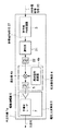
(第1の実施の形態) 図1は、本発明に係る第1の実施の形態であるFM光伝送システムの構成を示すブロック図である。本実施の形態のFM光伝送システムは、光ファイバケーブル92で接続された光送信機1と光受信機2とを備えて構成される。ここで、光送信機1は、狭帯域FM変調器3と、周波数変換器4と、電気/光変換部8とを備え、光受信機2は、光/電気変換部10と、FM復調器11と、低域通過フィルタ12とを備える。
Embodiments according to the present invention will be described below with reference to the drawings.
First Embodiment FIG. 1 is a block diagram showing a configuration of an FM optical transmission system according to a first embodiment of the present invention. The FM optical transmission system according to the present embodiment includes an optical transmitter 1 and an optical receiver 2 connected by an
図1において、狭帯域FM変調器3に入力される信号は、例えば、図2(a)に示すように、多チャンネルのAM映像信号が副搬送波多重されたAM多重映像信号20であり、狭帯域FM変調器3は、AM多重映像信号20の周波数帯に比較して十分に高い、例えばミリ波帯の高周波の搬送波信号を内部で発生して、入力されるAM多重映像信号20に従って上記搬送波信号を、実質的にFM信号の搬送波及び第1側波帯(第1側波帯は、第1上側波帯と第1下側波帯を含む。)のみが発生するような比較的小さい変調指数(変調指数に対応する変調度が10%以下)で周波数変調することにより、図2(b)に示す狭帯域FM信号27に変換して周波数変換器4の混合器4aに出力する。ここで、狭帯域FM信号27の搬送波信号の周波数が、元の入力信号に比較して十分に高いので、光伝送に必要な大きな変調指数を得ることができるという利点がある。
In FIG. 1, the signal input to the
狭帯域FM変調器3としては、例えば、バラクタ又はリアクタンストランジスタを用いた電圧制御型発振器を用いてもよいし、もしくは、マルチバイブレータによるデジタル的な弛緩発振器であってもよい。また、AM多重映像信号20を積分した後位相変調し、さらに、上記位相変調信号に平衡変調器により搬送波信号を合波して狭帯域FM信号を発生してもよい。
As the
狭帯域FM変調器3から出力される狭帯域FM信号27は、例えば非線形の電圧−電流特性を有するpin型ダイオードなどの非線形素子を備えた混合器4aで、局部信号発振器4bからの局部発振信号と混合した後、低域通過フィルタ5により低域ろ波することにより、図3に示すように、例えば中心周波数(搬送波周波数)が25GHzの狭帯域FM信号27は、例えば中心周波数(搬送波周波数)が5GHzの低周波の低域変換狭帯域FM信号27aにダウンコンバート(より低い周波数への周波数変換)される。
A narrowband FM signal 27 output from the
尚、この様にFM信号27をFM信号27aにダンウンコンバートする理由は次の通りである。即ち、一般に、電気信号と光信号との間での信号変換が可能な周波数の上限は、変換素子の周波数応答速度の限界により制限される。通常、搬送波周波数が10GHz以下でないと周波数応答が不可能となり、信号変換が行えないので、上記の様なダンウンコンバートが必要となる。
The reason why the FM signal 27 is converted into the
次に、上記の様にダウンコンバートされた低域変換狭帯域FM信号27aは、電気/光変換器8において、駆動増幅器6により増幅された後、レーザダイオードを備えた半導体レーザ7に入力される。
Next, the low-frequency conversion
半導体レーザ7は、入力された低域変換狭帯域FM信号に従って、内部で発生した光信号を強度変調することにより強度変調された光信号に変換して、変換した光信号を光ファイバケーブル92を介して相手方の光受信機2に送信する。
The
ここで、半導体レーザ7は、好ましい実施の形態において、例えば、波長1.2〜1.6μm帯のInP系材料の長波長半導体レーザ、0.98μm帯の半導体レーザ、発振波長0.78μm帯のGaAlAs系材料の半導体レーザなどを用いる。また、光ファイバケーブル92は、好ましい実施の形態において、例えば、コア径10〜300μm程度の光ファイバケーブル、もしくは、マルチモード光ファイバケーブル又はシングルモード光ファイバケーブルなどを用いる。
Here, in the preferred embodiment, the
光ファイバケーブル92を介して光受信機2に受信された光信号は、光/電気変換部10に入力され、フォトダイオード又はアバランシェフォトダイオードを備えた光電変換器13により電気信号に光電変換された後、低雑音増幅器14により所望の信号強度の電気信号に増幅される。増幅後の電気信号は、FM復調器11で周波数復調されて元のAM多重映像信号20に戻される。ここで、FM復調器11としては、広帯域で直線性の良好な遅延線型又はパルスカウント型のものが望ましく、図1においては遅延線型について示す。
The optical signal received by the optical receiver 2 via the
本実施の形態において、狭帯域FM変調器3は、搬送波信号を、実質的にFM信号の搬送波及び第1側波帯のみが発生するような比較的小さい変調指数で周波数変調して、狭帯域FM信号27を得ているので、狭帯域FM信号27は、実質的にAM信号に近い信号となっているので、狭帯域FM信号27の第1上側波帯と第1下側波帯のうちの一方のみを帯域通過フィルタでろ波して伝送するように構成してもよい。この場合、光受信機2では、光電変換後に振幅制限器(リミッタ)を通過させることにより元の狭帯域FM信号27を再生することができる。従って、より狭い帯域で送信することができるので、伝送効率を高くすることができ、送信駆動する消費電力も少なくて済む。
In the present embodiment, the
尚、本実施の形態では、図1に示す通り、遅延線型について示しており、高速のデジタル素子である2出力素子16、及び論理積素子17、遅延回路160を用いたものである。又、FM復調器11としては、上記構成に限定されるものではなく、複同調周波数弁別器、フォスター・シーレーの弁別器、比率検波器等の周波数弁別機能を有する回路を用いても良い。
In this embodiment, as shown in FIG. 1, the delay line type is shown, and the two-
以上説明したように、本実施の形態によれば、狭帯域FM変調し低域変換した後半導体レーザ7で強度変調することにより、送信用の光信号を得ているので、付加回路及び光ヘテロダイン検波回路が不要であって、それ故、従来例に比較して回路構成が簡単でありかつ安定性と信頼性に優れ、安価なFM信号伝送システムを提供することができる。また、狭帯域FM信号27を用いているので、狭帯域FM変調器3でほとんど変調歪を発生することがないので、信号品質が劣化することがない。
(第2の実施の形態)
図4は、本発明に係る第2の実施の形態であるFM光伝送システムの光送信機1aの構成を示すブロック図であり、図4において図1と同様のものについては同一の符号を付している。なお、光受信機2は、第1の実施の形態の図1のものを使用する。この第2の実施の形態は、図1の第1の実施の形態と比較して、狭帯域FM変調器3と周波数変換器4との間に、逓倍器21及び低域通過フィルタ22を挿入したことを特徴とし、狭帯域FM信号27を逓倍器21により複数逓倍して、帯域通過フィルタ22により所望の帯域の信号を帯域ろ波した後、周波数変換器4により、より低周波の周波数に周波数変換することを特徴としている。以下、第1の実施の形態との相違点について特に詳述する。
As described above, according to the present embodiment, an optical signal for transmission is obtained by narrow band FM modulation and low band conversion, and then intensity modulation by the
(Second Embodiment)
FIG. 4 is a block diagram showing the configuration of the optical transmitter 1a of the FM optical transmission system according to the second embodiment of the present invention. In FIG. 4, the same components as those in FIG. is doing. Note that the optical receiver 2 shown in FIG. 1 of the first embodiment is used. In the second embodiment, a
図4において、多チャンネルのAM映像信号を副搬送波多重してなるAM多重映像信号20は、狭帯域FM変調器3に入力され、狭帯域FM変調器3は、元のAM映像信号周波数(500MHz程度)に比較して高い搬送波周波数(f0=5GHz)を有する搬送波信号を、入力されるAM多重映像信号20に従って狭帯域FM変調を行って狭帯域FM信号27に変換する。狭帯域FM変換器3では、歪みによる信号劣化が発生せず、かつ多チャンネルの副搬送波多重信号の各チャンネルに対するFM変換スペクトルが第1側波帯以外の側波帯が顕著に現れない程度の変調指数の低い狭帯域のFM変調を行う。
In FIG. 4, an AM multiplexed
狭帯域FM信号27は逓倍器21に入力されて複数N逓倍され、狭帯域FM信号27の変調指数を増大させる。これにより元のAM多重映像信号20に比較して、図5に示すように、十分高い搬送波周波数(逓倍数N=5のとき、25GHz)を有し、かつ、信号帯域の広いFM信号に変換されることになる。従って、この逓倍作用によって、当該FM光伝送システムの光受信機2において必要となるCNRが得られるための変調指数を有するFM信号を得ることができる。
The narrowband FM signal 27 is input to the
次いで、このFM信号は帯域通過フィルタ22に入力されて、FM信号帯域以外の不要帯域のスペクトルを除去するように1つの狭帯域FM信号27が取り出された後、周波数変換器4により第1の実施の形態と同様に、図5に示すように、低域変換狭帯域FM信号27aにダウンコンバートされる。以下の処理は第1の実施の形態と同様である。
Next, this FM signal is input to the
以上説明したように、本実施の形態によれば、狭帯域FM信号27を逓倍しているので、従来例に比較してより大きな変調指数を有するFM信号を得ることができ、光受信機2で所望のCNRを得ることができる。 As described above, according to the present embodiment, since the narrowband FM signal 27 is multiplied, an FM signal having a larger modulation index than that of the conventional example can be obtained. A desired CNR can be obtained.
この様に、第1の実施の形態で述べた狭帯域FM変調器3が、元のAM多重映像信号20に比較して、十分高い周波数の搬送波信号を発生できない構成である場合でも、図4に示す様に逓倍器21を付加することにより、第1の実施の形態と同様の効果を発揮する。
(第3の実施の形態)
図6は、本発明に係る一実施の形態のFM光伝送システムの構成図である。
As described above, even when the
(Third embodiment)
FIG. 6 is a configuration diagram of an FM optical transmission system according to an embodiment of the present invention.
以下に、同図を用いて本実施の形態の構成を説明する。 The configuration of this embodiment will be described below with reference to FIG.
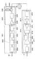
同図に示す様に、FM光伝送システムは、光送信機1001と光受信機1019から構成される。光送信機1001はFM変調器1004a、帯域除去フィルタ1005a、逓倍器1006a、帯域透過フィルタ1007a、周波数変換器1008aからなるFM変換部1002と、広帯域増幅器1009と半導体レーザ1010からなる電気/光変換部1003で構成される。光送信機1001からの光信号は光ファイバ92で伝送され光受信機1019に入力する。光受信機1019は光/電気変換器1014、前置増幅器1015からなる光/電気変換部1012とFM復調器1013、フィルタ1018によって構成される。本発明の抑圧手段は、帯域除去フィルタ1005aに対応する。
As shown in the figure, the FM optical transmission system includes an
以上のような構成により、以下、本実施の形態の動作を説明する。 The operation of the present embodiment will be described below with the above configuration.
即ち、図7(a)のような多チャンネルの副搬送波多重された映像信号であるAM信号20はFM変調器1004aによって、図7(b)に示すFM信号300に変換される。
That is, the
又、FM変調器1004aは、歪みが発生せず、かつ変調度の低い狭帯域のFM変調を行う。ここで、変調度の程度は、多チャンネル副搬送波多重信号20の各チャンネルに対するFM変換信号1300のスペクトルとして、第1側帯波1032以外の側帯波が顕著に現れない程度の低い値である。
The FM modulator 1004a performs narrowband FM modulation with no distortion and a low modulation degree. Here, the degree of modulation is such a low value that sidebands other than the
従って、図7(b)の様に第1側帯波1032はFM搬送波1031(周波数f0)か ら各々f1離れた領域に現れる。このFM信号1300が帯域除去フィルタ1005aを 通過した後の信号1301を図7(c)に示す。帯域除去フィルタ1005aの中心周波数は図7(b)のFM搬送波1031の周波数f0に調整されており、かつ中心周波 数での抑圧度は大きくない。従って帯域除去フィルタ1005a通過後はFM搬送波1031からレベル差1035だけ下がったFM搬送波1034となる。また側帯波1032はFM搬送波1034から周波数がf1離れているため、位相変化やレベル変動の影響が帯域除去フィルタ1005aによっておこらないようになっている。従って帯域除去フィルタ1005aによりFM搬送波1034の部分だけを選択的にレベル差1035だけ抑制することになる。これによりFM変調器1004aで狭帯域FM変調された信号は搬送波と側帯波とのレベル差1036が帯域除去フィルタ1005a通過前のレベル差1033よりも小さくなったことから帯域除去フィルタ1005aによってFM変調度が見かけ上、増大したことになる。
Accordingly, as shown in FIG. 7 (b), the
この信号1301は逓倍器1006aに入力しN逓倍され、さらに変調度を増大させる。これにより元のAM信号に比べ、図8(b)に示すように十分高いFM搬送波(例えばN×f0=25GHz)を有し信号帯域の広いFM信号1302に変換さ れることになる。従ってこの逓倍作用によって光伝送において光受信機で必要なC/Nが得られるための変調度を有するFM信号1302を得ることができる。そして、FM信号帯域以外の不要帯域のスペクトルを帯域透過フィルタ1007aで除去した後、周波数変換器1008a、たとえばミキサーなどによって信号成分は低周波側にダウンコンバートされる。このようにして図8(c)のようなFM変換信号1027を得る。このFM変換信号1027を広帯域増幅器1009を介して半導体レーザ1010で光信号とし、光ファイバーケーブル92を伝搬する。
This
光受信機1019の動作に関しては、上記実施の形態1で説明した光受信機2と同様である(図1参照)。尚、本実施の形態では、図6に示す通り、遅延線型について示しており、高速のデジタル素子である2出力素子1016、及び論理積素子1017、遅延回路1160を用いたものである。又、FM復調器1013としては、上記構成に限定されるものではなく、複同調周波数弁別器、フォスター・シーレーの弁別器、比率検波器等の周波数弁別機能を有する回路を用いても良い。
The operation of the
以上のような構成により、FM変調度が小さいFM変調器を用いてFM変換を行い、帯域除去フィルタで1次的なFM変調度増大を図り、その後の逓倍による2次的なFM変調度増大によって、所望のFM変調度を得ることにより、逓倍器の逓倍数を大きくすることなく、簡単な構成の電気回路による信号処理で副搬送波多重されたAM多チャンネル信号を一括してFM信号に変換できる。
(第4の実施の形態)
図9は、本発明に係る一実施の形態のFM光伝送システムの構成図である。以下、図7〜図9を用いて、本実施の形態の構成を説明する。
With the configuration as described above, FM conversion is performed using an FM modulator having a small FM modulation degree, the primary FM modulation degree is increased by a band elimination filter, and the secondary FM modulation degree is increased by subsequent multiplication. Thus, by obtaining a desired FM modulation degree, AM multichannel signals multiplexed by subcarriers are converted into FM signals collectively by signal processing by an electric circuit having a simple configuration without increasing the multiplication number of the multiplier. it can.
(Fourth embodiment)
FIG. 9 is a configuration diagram of an FM optical transmission system according to an embodiment of the present invention. Hereinafter, the configuration of the present embodiment will be described with reference to FIGS.
図9において、光送信機1001は、FM変調器1004b、周波数変換器1008b、帯域除去フィルタ1005b、逓倍器1006b、帯域透過フィルタ1007b、周波数交換器1008aからなるFM変換部1002と、上記実施の形態3と同様の電気/光交換部1003により構成される。尚、光受信機1019に関しては、実施の形態3と同様のため説明は省略する。
In FIG. 9, the
以上のような構成により、以下、本実施の形態の動作を説明する。 The operation of the present embodiment will be described below with the above configuration.
即ち、多チャンネルの副搬送波多重されたAM信号20は、元のAM信号周波数に比べ十分高いFM搬送波(例えばfh=25GHz)を有する狭帯域FM変 調器1004bによって図8(a)のFM信号1300aに変換される。
That is, the multi-channel subcarrier multiplexed
狭帯域FM変調器1004bでは歪みによる信号劣化が発生せず、かつ多チャンネル副搬送波多重信号の各チャンネルに対するFM変換スペクトルとして、第1側帯波1032a以外の側帯波が顕著に現れない程度の変調度の低い狭帯域のFM変調を行う。この信号を周波数変換器1008bにより低周波側にダウンコンバートし、スペクトル1300bを得る。ここでは説明の便宜上、周波数変換器1008bでダウンコンバートした際の中心周波数をf0 としておく。
以下、帯域除去フィルタ1005bによりFM搬送波1031bのみを選択的にレベル差1035だけ抑圧し、図8(b)のスペクトル1301の信号を得る。以後の動作は第3の実施例と同様である。
Thereafter, only the FM carrier 1031b is selectively suppressed by the
このように本実施の形態では、第3の実施の形態の効果に加えて、FM変調器として十分高いFM搬送波を有するものを用いることにより周波数可変範囲を拡大し、FM変調器に入力する信号の帯域をより広帯域にする事ができる。 As described above, in this embodiment, in addition to the effects of the third embodiment, a frequency variable range is expanded by using an FM modulator having a sufficiently high FM carrier, and the signal input to the FM modulator. Can be made wider.
ところで、上述した各実施の形態におけるFM変調器での変調度は、10%以下であることが望ましい。変調度が10%以下であれば、図7(b)の多チャンネルの副搬送波多重された信号のFM変調スペクトル1300の周波数f0−f2からf0+f2までの周波数域で信号エネルギーの98%以上を確保することが出来、狭帯域FMが可能となる。
By the way, it is desirable that the modulation degree in the FM modulator in each of the above-described embodiments is 10% or less. If the degree of modulation is 10% or less, the signal energy in the frequency range from frequency f 0 −f 2 to frequency f 0 + f 2 of the
以上の様に、上記実施の形態によれば、例えば、副搬送波多重された複数の信号をFM変調器においてFM信号に変換し、帯域除去フィルタでFM信号中の中心周波数成分を抑圧し、前記中心周波数成分の抑圧されたFM信号を周波数逓倍器によって逓倍し、前記周波数逓倍信号の所望の変調度の信号を周波数変換器にて低周波側の光伝送帯域にシフトさせて光信号に変換して伝送する。 As described above, according to the above-described embodiment, for example, a plurality of subcarrier multiplexed signals are converted into FM signals by the FM modulator, and the center frequency component in the FM signal is suppressed by the band elimination filter. The FM signal in which the center frequency component is suppressed is multiplied by a frequency multiplier, and a signal having a desired modulation degree of the frequency multiplied signal is shifted to an optical transmission band on the low frequency side by a frequency converter and converted into an optical signal. And transmit.
又、上記実施の形態によれば、副搬送波多重された複数のAM信号を、被変調波であるAM信号に比べ十分に周波数の高いミリ波帯の高周波の搬送波信号を発生するFM変調器においてFM信号に変換し、前記FM信号を周波数変換器にて低周波側にシフトさせ、帯域除去フィルタでそのシフトされたFM信号中の中心周波数成分を抑圧し、所望の変調度を見かけ上高めた後、前記信号を周波数逓倍器によって逓倍し、所望の変調度の前記周波数逓倍信号を周波数変換器にて低周波側の光伝送帯域にシフトさせ、光信号に変換して伝送するものである。 Further, according to the above-described embodiment, in the FM modulator that generates a plurality of subcarrier-multiplexed AM signals to generate a high-frequency carrier signal in the millimeter wave band having a sufficiently higher frequency than the AM signal that is the modulated wave. An FM signal is converted, the FM signal is shifted to a low frequency side by a frequency converter, and a center frequency component in the shifted FM signal is suppressed by a band elimination filter, and a desired modulation degree is apparently increased. Thereafter, the signal is multiplied by a frequency multiplier, and the frequency-multiplied signal having a desired modulation degree is shifted to a low-frequency side optical transmission band by a frequency converter, converted into an optical signal and transmitted.
尚、以上述べた実施の形態では、FM信号中の中心周波数成分を抑圧した後、中心周波数成分の抑圧されたFM信号を逓倍し、低周波側にシフトする構成について述べたがこれに限らず例えば、FM信号中の中心周波数成分を抑圧するのみの構成でもよい。この場合、単一の副搬送波を用いた信号、又は複数の副搬送波により多重化された複数の信号をFM変調手段を利用してFM信号に変換し、抑圧手段により前記FM信号中の中心周波数成分を抑圧し、前記中心周波数成分の抑圧されたFM信号に基づいて光信号を生成し、前記光信号を伝送する構成となる。これにより、AM信号を直接電気的なFM信号に変換する場合に、FM変調器での変調指数が見かけ上大きくとれるので、FM変調器で歪みを大きくすることなく、より一層C/N値の改善が出来るという効果を発揮する。 In the above-described embodiment, the configuration has been described in which the center frequency component in the FM signal is suppressed, and then the FM signal in which the center frequency component is suppressed is multiplied and shifted to the low frequency side. For example, a configuration that only suppresses the center frequency component in the FM signal may be used. In this case, a signal using a single subcarrier or a plurality of signals multiplexed by a plurality of subcarriers is converted to an FM signal using FM modulation means, and the center frequency in the FM signal is suppressed by suppression means. A component is suppressed, an optical signal is generated based on the FM signal in which the center frequency component is suppressed, and the optical signal is transmitted. As a result, when the AM signal is directly converted into an electrical FM signal, the modulation index in the FM modulator can be apparently increased, so that the C / N value can be further increased without increasing the distortion in the FM modulator. Demonstrate the effect of improvement.
又、上記実施の形態では、帯域抑圧フィルタは、例えば、FM変換する際の中心周波数付近のスペクトルを選択的に抑圧するフィルタであり、抑圧度は10dB程度あればよい。 In the above embodiment, the band suppression filter is, for example, a filter that selectively suppresses the spectrum near the center frequency when FM conversion is performed, and the suppression degree may be about 10 dB.
又、本発明の抑圧手段は、上記実施の形態では、帯域除去フィルタであり、第1周波数変換手段(上記実施の形態では、図9の周波数変換器1008bに対応する)により低周波側にシフトされたFM信号の中心周波数成分を抑圧する場合について述べたが、これに限らず例えば、抑圧手段は、FM変調手段により変換されたFM信号の中心周波数成分を、上記シフトがなされる前の段階で抑圧し、その後、上記の様に低周波側にシフトさせる構成でもよい。この場合の構成としては、例えば、次のようになる。即ち、副搬送波多重された複数のAM信号をキャリア周波数が被変調波であるAM信号に比べ十分に周波数の高いミリ波帯においてFMキャリアを有するFM変調器においてFM信号に変換し、帯域除去フィルタでFM信号中の中心周波数成分を抑圧し、所望の変調度を見かけ上高めた後、前記信号を第1周波数変換器にて低周波側にシフトさせ、前記信号を周波数逓倍器によって逓倍し、所望の変調度の前記周波数逓倍信号を第2周波数変換器にて低周波側の光伝送帯域にシフトさせ、光信号に変換して伝送するものである。この場合の構成図としては、図9において、周波数除去フィルタ1005bと周波数変換器1008bの配置の順番を入れ替えたものと同じである。
The suppression means of the present invention is a band elimination filter in the above embodiment, and is shifted to the low frequency side by the first frequency conversion means (corresponding to the
又、上記実施の形態では、副搬送波多重された複数の信号、即ち、複数の副搬送波により多重化された複数のチャンネルの信号をFM変調手段を利用してFM信号に変換する場合を中心に述べたが、これに限らず例えば、FM信号に変換される信号は、単一の副搬送波を用いた単一のチャンネルの信号でも勿論良い。この場合でも、上記と同様の効果を発揮する。
(第5の実施の形態)
図10は、本発明の実施の形態5のFM光伝送システムの構成を示すブロック図である。同図を参照しながら、以下に本実施の形態の構成を説明する。
In the above embodiment, a plurality of sub-carrier multiplexed signals, that is, a plurality of channel signals multiplexed by a plurality of sub-carriers are converted into FM signals using FM modulation means. As described above, the present invention is not limited to this. For example, the signal converted into the FM signal may be a single channel signal using a single subcarrier. Even in this case, the same effect as described above is exhibited.
(Fifth embodiment)
FIG. 10 is a block diagram showing a configuration of the FM optical transmission system according to the fifth embodiment of the present invention. The configuration of the present embodiment will be described below with reference to FIG.
同図に示す様に、本FM光伝送システムは光送信機2001と光受信機2013とを備えており、光送信機2001と光受信機2013とは光ファイバーケーブル92により接続されている。光送信機2001はAM/FM変換部2002と、電気/光変換部2003とを備えている。AM/FM変換部2002は、AM/FM変換器2004と、逓倍器2005と、帯域透過フィルタ2006と、周波数変換器2007とを備えている。電気/光変換部2003は、広帯域増幅器2008と、半導体レーザ2009と、光ファイバグレーティング2011と、光サーキュレータ2010とを備えている。
As shown in the figure, the FM optical transmission system includes an
本FM光伝送システムは、上述した実施の形態の構成とほぼ同様であるが、光ファイバグレーティング2011を備えたことに特徴を有している。
The FM optical transmission system is substantially the same as the configuration of the above-described embodiment, but is characterized in that an
図11,図12はこのFM光伝送システムの動作を説明するための信号スペクトルの概念図であり、図13は光ファイバグレーティング2011から構成される群遅延補償手段の構成図であり、図14(a)〜図14(c)は光ファイバグレーティング2011の動作を示すための概念図である。
FIGS. 11 and 12 are conceptual diagrams of signal spectra for explaining the operation of the FM optical transmission system, and FIG. 13 is a configuration diagram of a group delay compensation unit including an
これらの図を参照しながら、次に、本実施の形態の光ファイバグレーティング2011の動作を中心に説明する。 Next, the operation of the optical fiber grating 2011 of the present embodiment will be mainly described with reference to these drawings.
尚、図11(a)〜図12(b)に示す内容は、上記実施の形態で説明したものと基本的に同じである。即ち、図11(a)、図11(b)において、20は上述した元のAM信号(帯域f1〜f2)であり、2061はAM/FM変換器2004によって変換されたFM信号である。2062はFM信号2061のスペクトルにおける第1側波帯であり、FM搬送波2063(周波数f0)を中心にして、それぞれf1離れた領域に現れる。又、図12(a)、図12(b)において、2064は、FM信号2061が逓倍器2005によりN倍に逓倍されて得られた搬送波2063’を有する、信号帯域の広いFM逓倍信号である。搬送波2063’の周波数は、例えば、NF0(NXf0)=25GHzであり、元のAM信号20に比べて、十分周波数が高い。
The contents shown in FIGS. 11A to 12B are basically the same as those described in the above embodiment. That is, in FIGS. 11A and 11B, 20 is the original AM signal (bands f 1 to f 2 ) described above, and 2061 is an FM signal converted by the AM /
即ち、上記実施の形態と同様にして得られたFM周波数変換信号2065を広帯域増幅器2008を介して半導体レーザ2009に入力し、ここでFM光信号2066に変換する。そして、作成したFM光信号2066を光サーキュレータ2010を介して光ファイバグレーティング2011に入力する。
That is, the FM
光ファイバグレーティング2011は、図13に示すように、長尺方向で屈折率分布の間隔を変えることにより光ファイバグレーティング2011で反射する光信号内の群遅延特性を任意に設定できるように構成されている。
As shown in FIG. 13, the
ここで、光ファイバグレーティング2011を通過させない場合のFM光信号2066の群遅延特性の例を図14(a)に示す。FM光信号2066は、光送信機2001ならびに光ファイバ92を通過することにより、群遅延特性が周波数によって不揃いとなる。図14(a)に示した例では、周波数が高くなるほど群遅延量が小さくなっている。
Here, an example of the group delay characteristic of the FM
これに対して、上述した光ファイバグレーティング2011の遅延調整量を、図14(b)に示すように、図14(a)の群遅延特性とは逆相の関係になるように設定する。これにより、図14(a)に示す群遅延特性と図14(b)に示す群遅延調整量とが相殺されて図14(c)に示すように、周波数に関係なく群遅延特性が均一化される。
On the other hand, the delay adjustment amount of the above-described
以上のような光ファイバグレーティング2011の作用により群遅延特性が調整されたFM光信号2066は、光サーキュレータ2010を介して光ファイバーケーブル92に伝送される。
The FM
一方、光ファイバーケーブル92から光受信機2013に入力されたFM光信号2066は、光/電気変換部2015(フォトダイオードまたはアバランシェフォトダイオードからなる光/電気変換器2016と前置増幅器2017から構成されている)によって電気信号に変換された後、FM/AM復調部2014(リミッタアンプ2018、分岐素子2019、遅延回路2020、ミキサ2021,ローパスフィルタ2022から構成されている)に入力され、ここで、所望の信号強度に増幅されて元のAM信号21に復調される。復調されたAM信号21は光ファイバグレーティング2011により伝送系での群遅延が相殺され位相特性の良好な信号となっている。
On the other hand, an FM
以上のような構成により、FM変調度が小さいAM/FM変換器2004を用いてAM/FM変換を行い、その後の逓倍操作による2次的なFM変調度増大によって、所望のFM変調度を得ることができる。これにより、逓倍器2005の逓倍数を大きくすることなく、簡単な構成の電気回路による信号処理で副搬送波多重されたAM多チャンネル信号を一括してFM信号に変換できると共に、変復調系並びに伝送系での群遅延を光ファイバグレーティング2011及び光サーキュレータ2010で構成される群遅延補償手段によって、位相特性の優れたAM信号21に復調することができる。
With the configuration as described above, AM / FM conversion is performed using the AM /
なお、一般に、図14(a)に示す群遅延特性は所要帯域で数十〜百数十psec程度である。そのため、光ファイバグレーティング2011で補償する群遅延量は半導体レーザ2009の波長拡がり(数〜十数GHz)を考慮すれば、光ファイバグレーティング2011で数百psec/nmオーダーの屈折率分布を逆相で形成して図14(b)の補償特性となるようにすればよい。
In general, the group delay characteristic shown in FIG. 14A is about tens to hundreds of psec in the required band. Therefore, the group delay amount compensated by the
このような群遅延補償機能を実施して伝送系全体で群遅延補償を行うことにより、群遅延特性の必ずしも良くない安価な回路素子を用いても、全体としての群遅延特性の優れたFM光伝送システムを構成すれことができた。これにより、低コスト化を促進できて、加入者系を含むアクセス網に対して導入が容易な構成を実現できる。
(第6の実施の形態)
図15は本発明の実施の形態6のFM光伝送システムの構成を示すブロック図である。このFM光伝送システムは、基本的には実施の形態5のFM光伝送システムの構成と同様の構成を備えており、同一ないし同様の構成には同一の符号を付し、それらについての説明は省略する。
By implementing such a group delay compensation function and performing group delay compensation in the entire transmission system, FM light having excellent group delay characteristics as a whole can be obtained even if inexpensive circuit elements having poor group delay characteristics are used. The transmission system could be configured. Thereby, cost reduction can be promoted, and a configuration that can be easily introduced into an access network including a subscriber system can be realized.
(Sixth embodiment)
FIG. 15 is a block diagram showing the configuration of the FM optical transmission system according to the sixth embodiment of the present invention. This FM optical transmission system basically has the same configuration as the configuration of the FM optical transmission system according to the fifth embodiment, and the same reference numerals are given to the same or similar configurations, and description thereof will be omitted. Omitted.
このFM光伝送システムは、光ファイバグレーティング2011に温度制御部2025を備えたことに特徴がある。温度制御部2025は、例えば、ヒーター及びサーモスタットといった構成を備えて任意に光ファイバグレーティング2011の雰囲気温度を可変させるものであって、雰囲気温度を変動させることで光ファイバグレーティング2011の線膨張を調整してその長尺方向寸法を伸縮させることができるようになっている。光ファイバグレーティング2011の長尺方向寸法を伸縮させることで、このFM光伝送システムでは、光ファイバグレーティング2011の屈折率分布の間隔を変えることが可能となっている。
This FM optical transmission system is characterized in that the
なお、上述した各実施の形態では、群遅延補償素子として光ファイバグレーティング2011を用いたが、伝送系の群遅延特性が線形的に変化する場合には分散補償ファイバを用いても良いのはいうまでもない。さらには、上述した各実施の形態では、副搬送波多重された複数の信号を、FM変換→逓倍処理→低周波周波数変換処理→光信号変換といった処理を施した後、送信するFM光伝送システムにおいて本発明を実施したが、本発明は、このようなFM光伝送システムに対してのみ実施できるものではなく、副搬送波多重された複数の信号を一括してFM光信号に変換して送信する光送信機を備えたFM光伝送システムであれば、どのような構成を備えたものであっても同様に実施できるのはいうまでもない。
In each of the above-described embodiments, the
このような構成(温度制御部2025)を備えることにより、実施の形態5の効果に加えて光ファイバグレーティング2011によって生じる群遅延補償特性を可変することができ、システム上の伝送遅延の変動に応じて、群遅延補償程度を微調整することができるうえに、光ファイバグレーティング2011の設置環境温度の変動により分散補償の程度が変動することを回避することもできる。
By providing such a configuration (temperature control unit 2025), in addition to the effects of the fifth embodiment, the group delay compensation characteristic generated by the
なお、本実施の形態では温度制御部2025を光ファイバグレーティング2011に設けたが、この限りではなくファイバの長尺方向の張力を可変する事によっても同様な作用効果を得ることができる。
In the present embodiment, the
また光ファイバグレーティング2011の屈折率分布のある範囲の中で局所的に加熱・冷却する機能又は、張力を可変する機能を有すれば所定の周波数域のみの群遅延補償特性を変更することもできる。
(第7の実施の形態)
図16は本発明の実施の形態7のFM光伝送システムの構成図である。
Further, the group delay compensation characteristic only in a predetermined frequency range can be changed if the
(Seventh embodiment)
FIG. 16 is a configuration diagram of an FM optical transmission system according to the seventh embodiment of the present invention.
本FM光伝送システムは、基本的には実施の形態5と同様の構成を備えており、同一ないし同様の部分には同一の符号を付し、それらについての説明は省略する。 The FM optical transmission system basically has the same configuration as that of the fifth embodiment, and the same or similar parts are denoted by the same reference numerals, and description thereof is omitted.
このFM光伝送システムは、光ファイバグレーティング2011及び光サーキュレータ2010を光受信機2013内の光/電気変換部2015に設けた点に特徴がある。このような構成を備えることにより、実施の形態5における効果に加えて、光ファイバーケーブル92および光受信機2013で生じる群遅延のばらつき(位相のずれ)をさらに補償することができるようになっている。
This FM optical transmission system is characterized in that an
尚、上記実施の形態の周波数逓倍器は、例えば、入力周波数に対してn倍の周波数に高めるもので、トランジスターやFET、可変容量ダイオードなどの非直線性を利用して高調波を発生するものである。 The frequency multiplier of the above embodiment is, for example, one that increases the frequency to n times the input frequency, and generates harmonics by using non-linearity such as a transistor, FET, or variable capacitance diode. It is.
又、上記実施の形態の周波数変換器は、周波数逓倍器と同様に非線形回路素子の周波数混合作用を利用して、周波数を高周波側もしくは低周波側に変換するものである。 The frequency converter of the above embodiment converts the frequency to the high frequency side or the low frequency side by utilizing the frequency mixing action of the nonlinear circuit element as in the case of the frequency multiplier.
尚、上記実施の形態では、補償手段は、上記の通り1つの半導体レーザを有する光送信装置に設けられた場合について述べたが、これに限らず例えば、図17で述べた従来のFM信号光伝送システムの送信側又は受信側に設ける構成でも勿論良い。 In the above-described embodiment, the case where the compensation means is provided in the optical transmission device having one semiconductor laser as described above is described. However, the present invention is not limited to this. For example, the conventional FM signal light described in FIG. Of course, a configuration provided on the transmission side or the reception side of the transmission system is also possible.
以上述べたところから明らかなように本発明は、従来に比べて回路構成が簡単でありながら、安定性、信頼性に優れ、信号品質が良好であるという長所を有する。 As is apparent from the above description, the present invention has advantages in that the circuit configuration is simpler than that of the prior art, and the stability and reliability are excellent, and the signal quality is good.
又、本発明は、伝送時の位相のずれに起因する歪みを抑制出来るという長所を有する。 Further, the present invention has an advantage that distortion caused by a phase shift during transmission can be suppressed.
本発明にかかるFM信号光受信装置は、伝送時の位相のずれに起因する歪みを抑制出来るという効果を有し、FM信号光受信装置等として有用である。 The FM signal light receiving apparatus according to the present invention has an effect of suppressing distortion caused by a phase shift during transmission, and is useful as an FM signal light receiving apparatus or the like.
1,1a…光送信機
2…光受信機
3…狭帯域FM変調器
4…周波数変換器
4a…混合器
4b…局部信号発振器
5…低域通過フィルタ
6…駆動増幅器
7…半導体レーザ
8…電気/光変換部
92…光ファイバケーブル
10…光/電気変換部
11…FM復調器
12…低域通過フィルタ
13…光電変換器
14…低雑音増幅器
20,20a…AM多重映像信号
21…逓倍器
22…帯域通過フィルタ
27…狭帯域FM信号
27a…低域変換狭帯域FM信号
DESCRIPTION OF SYMBOLS 1, 1a ... Optical transmitter 2 ...
Claims (6)
前記補償手段から出力されるFM光信号をFM電気信号に変換する光/電気変換手段と、
前記光/電気変換手段により変換された前記FM信号をAM信号に復調する復調手段と、
を備えたことを特徴とするFM信号光受信装置。 Compensation means for performing dispersion compensation or group delay compensation on the FM optical signal transmitted via the optical fiber;
An optical / electrical conversion means for converting an FM optical signal output from the compensation means into an FM electrical signal;
Demodulation means for demodulating the FM signal converted by the optical / electrical conversion means into an AM signal;
An FM signal light receiving apparatus comprising:
Priority Applications (1)
| Application Number | Priority Date | Filing Date | Title |
|---|---|---|---|
| JP2006035826A JP2006148977A (en) | 1998-01-27 | 2006-02-13 | Fm signal optical receiver |
Applications Claiming Priority (4)
| Application Number | Priority Date | Filing Date | Title |
|---|---|---|---|
| JP1451798 | 1998-01-27 | ||
| JP6278398 | 1998-03-13 | ||
| JP24008698 | 1998-08-26 | ||
| JP2006035826A JP2006148977A (en) | 1998-01-27 | 2006-02-13 | Fm signal optical receiver |
Related Parent Applications (1)
| Application Number | Title | Priority Date | Filing Date |
|---|---|---|---|
| JP01498399A Division JP3782599B2 (en) | 1998-01-27 | 1999-01-22 | FM signal optical transmission equipment |
Publications (1)
| Publication Number | Publication Date |
|---|---|
| JP2006148977A true JP2006148977A (en) | 2006-06-08 |
Family
ID=36628029
Family Applications (1)
| Application Number | Title | Priority Date | Filing Date |
|---|---|---|---|
| JP2006035826A Pending JP2006148977A (en) | 1998-01-27 | 2006-02-13 | Fm signal optical receiver |
Country Status (1)
| Country | Link |
|---|---|
| JP (1) | JP2006148977A (en) |
-
2006
- 2006-02-13 JP JP2006035826A patent/JP2006148977A/en active Pending
Similar Documents
| Publication | Publication Date | Title |
|---|---|---|
| US6556327B1 (en) | Signal converter, optical transmitter and optical fiber transmission system | |
| US5212579A (en) | Method and apparatus for communicating amplitude modulated signals over an optical communication path | |
| US7421199B2 (en) | System and method for subcarrier modulation as supervisory channel | |
| US6643470B1 (en) | FM signal converter, FM signal optical transmitter and FM signal optical receiver | |
| JP3003575B2 (en) | Optical transmission method and optical transmission device for subcarrier multiplexed signal | |
| JP2000124876A (en) | Optical transmission system for frequency multiple signal | |
| JP4332616B2 (en) | Method and apparatus for signal processing of modulated light | |
| JP3467507B2 (en) | High-frequency signal transmission method and high-frequency signal transmission device using optical carrier | |
| US6452706B1 (en) | FM signal optical transmission apparatus and FM signal optical reception apparatus | |
| US20020075539A1 (en) | Wavelength division multiplex optical transmitter, wavelength division multiplex optical receiver, optical transmission device, and optical transmission system and method | |
| JPH1174847A (en) | Fm modulator | |
| WO2006011410A1 (en) | Modulator, optical transmitter and optical transmission apparatus | |
| JP4410760B2 (en) | Optical signal receiver, optical signal receiver and optical signal transmission system | |
| US6658216B1 (en) | Voltage controlled oscillator, FM signal optical transmitter, FM signal optical receiver and FM signal optical transmission system | |
| EP1646164B1 (en) | Optical signal transmitter and optical signal transmission system | |
| JP3782599B2 (en) | FM signal optical transmission equipment | |
| US20060116143A1 (en) | Distortion generator circuit, pre-distortion circuit, optical signal transmitter using the same, and optical signal transmission system | |
| JP2006287410A (en) | Optical transmitter, optical receiver, and optical transmission system | |
| JP2006148977A (en) | Fm signal optical receiver | |
| JP3863463B2 (en) | Signal transmission method and signal transmission system | |
| JP4374011B2 (en) | Optical signal transmitter and optical signal transmission system | |
| JPH09326769A (en) | Modulation system conversion circuit and optical signal transmitter | |
| JP2012249122A (en) | Optical communication system and optical transmitter | |
| JP2000349560A (en) | Voltage controlled oscillator, optical fm signal transmitter, optical fm signal receiver and optical fm signal transmission system | |
| JP2001168643A (en) | Fm signal converter, fm signal optical transmitter and fm signal optical receiver |
Legal Events
| Date | Code | Title | Description |
|---|---|---|---|
| A131 | Notification of reasons for refusal |
Free format text: JAPANESE INTERMEDIATE CODE: A131 Effective date: 20071218 |
|
| A02 | Decision of refusal |
Free format text: JAPANESE INTERMEDIATE CODE: A02 Effective date: 20080422 |