JP2006145182A - Header for hot water supply system - Google Patents
Header for hot water supply system Download PDFInfo
- Publication number
- JP2006145182A JP2006145182A JP2004339658A JP2004339658A JP2006145182A JP 2006145182 A JP2006145182 A JP 2006145182A JP 2004339658 A JP2004339658 A JP 2004339658A JP 2004339658 A JP2004339658 A JP 2004339658A JP 2006145182 A JP2006145182 A JP 2006145182A
- Authority
- JP
- Japan
- Prior art keywords
- hot water
- water supply
- pipe
- temperature
- supply pipe
- Prior art date
- Legal status (The legal status is an assumption and is not a legal conclusion. Google has not performed a legal analysis and makes no representation as to the accuracy of the status listed.)
- Pending
Links
Images

Abstract
Description
本発明は、貯湯タンクに接続して給湯端末に湯水を供給する給湯管と、湯水を前記貯湯タンクに返送する返送管とに接続して、給湯管内部の湯水の温度によって湯水の流れる配管を切替える給湯システム用ヘッダーに関するものである。 The present invention connects a hot water supply pipe connected to a hot water storage tank to supply hot water to a hot water supply terminal, and a return pipe for returning the hot water to the hot water storage tank. The present invention relates to a header for a hot water supply system to be switched.
従来より、特開平7−103569号公報に開示されているように、貯湯タンクに貯蔵された湯水を給湯管を介して、給湯栓等の給湯端末から使用者に提供する給湯システムが使用されている。 Conventionally, as disclosed in JP-A-7-103569, a hot water supply system that provides hot water stored in a hot water storage tank to a user from a hot water supply terminal such as a hot water tap through a hot water supply pipe has been used. Yes.
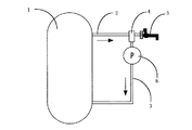
この給湯システムは、図1に示すように、高温の湯水を貯蔵している貯湯タンク1から給湯管2を介して給湯栓5が備えられているものである。ここで、貯湯タンク1は保温構造となっているので、貯蔵している湯水の温度が低下しにくい。しかし、給湯管2は、保温構造を有する配管とすると高価格となるために、通常の金属管が使用されることが多い。この場合、給湯管2の内部の湯水の温度が低下すると、給湯栓5を開栓した後も、しばらくは給湯配管2の内部の低温の湯水が供給されることになる。これを防止するために、貯湯システム用ヘッダー4と返送管3を設けて、給湯管2の湯水の温度が低い時は、給湯栓5が開栓されても、一定時間、循環ポンプ6を運転させて、貯湯タンク1→給湯管2→貯湯システム用ヘッダー4→返送管3→貯湯タンク1と湯水を循環させた後、給湯管2の内部の湯水の温度が一定以上となった後に、給湯栓5から湯水を供給するようにしている。
As shown in FIG. 1, this hot water supply system is provided with a
ここで、貯湯システム用ヘッダー4は、給湯管2の湯水の温度を測定するセンサと、この温度に応じて、湯水の経路を変更する切替弁9とを備えている。ここで、センサと切替弁9を動作させるアクチュエータとを兼ねるために、図4に示すように、形状記憶合金を用いることがある。このものは、図4(a)のように、湯水の温度が低温の時は、形状記憶合金のバネ10が縮んで、切替弁9は給湯栓5の側を塞ぎ、湯水は給湯管2から返送管3へとEの方向に流れる。一方、図4(b)のように、湯水が高温となると、バネ10が伸びて、切替弁9は返送管3の側を塞ぎ、湯水は給湯管2から給湯栓5へとFの方向に流れる。この構造だと、湯水が低温から高温になった場合に、バネ10の温度変化の追従性が悪く、このために、給湯栓5から湯水が供給されるまでの時間が長くなるという問題があった。これを解決するための構造が、特開平3−33578号公報や実開平6−14820号公報に開示されている。
しかしながら、特開平3−33578号公報や実開平6−14820号公報に記載されている構造では、構造が複雑となり、価格も高くなるおそれがあった。特に、実開平6−14820号公報に記載されている構造では、高価な形状記憶合金のバネが2本必要となっている。 However, the structures described in Japanese Patent Application Laid-Open Nos. 3-33578 and 6-14820 have a problem in that the structure is complicated and the price is high. In particular, in the structure described in Japanese Utility Model Laid-Open No. 6-14820, two expensive shape memory alloy springs are required.
本発明はこのような点に鑑みなされたものであって、その目的とするところは、簡易な構造で、湯水の温度変化に対する切替弁の追従性が良好な掲示用記憶合金を用いた貯湯システム用ヘッダーを提供することにある。 The present invention has been made in view of the above points, and the object of the present invention is to provide a hot water storage system using a memory alloy for posting with a simple structure and good follow-up performance of the switching valve with respect to changes in the temperature of hot water. Is to provide headers for use.
上記課題を解決するために本発明の給湯システム用ヘッダーは、貯湯タンクに接続して給湯端末に湯水を供給する給湯管と、湯水を前記貯湯タンクに返送する返送管とに接続して、給湯管内部の湯水の温度によって湯水の流れ方向を切替える切替弁を内蔵し、給湯管内部の湯水が低温の時は給湯管から返送管に湯水を返送して、給湯管内部の湯水が高温の時は給湯端末に湯水を供給する給湯システム用ヘッダーであって、前記切替え弁に接続して湯水の温度によって形状の変化する形状記憶合金からなるバネを有してなり、前記切替弁は湯水が低温の時は湯水の全部又は一部が通過する貫通孔を具備していることを特徴としている。 In order to solve the above problems, a header for a hot water supply system of the present invention is connected to a hot water supply pipe connected to a hot water storage tank to supply hot water to a hot water supply terminal, and a return pipe for returning the hot water to the hot water storage tank. There is a built-in switching valve that switches the flow direction of hot water depending on the temperature of the hot water inside the pipe. When the hot water inside the hot water pipe is cold, hot water is returned from the hot water pipe to the return pipe, and when the hot water inside the hot water pipe is hot. Is a header for a hot water supply system for supplying hot water to a hot water supply terminal, and has a spring made of a shape memory alloy that is connected to the switching valve and changes its shape depending on the temperature of the hot water. Is characterized by having a through-hole through which all or part of the hot water passes.
本発明にあっては、切替え弁に接続して湯水の温度によって形状の変化する形状記憶合金からなるバネを有してなり、切替弁は湯水が低温の時は湯水の全部又は一部が通過する貫通孔を具備しているので、簡易な構造で、湯水の温度変化に対する切替弁の追従性が良好な掲示用記憶合金を用いた貯湯システム用ヘッダーを提供することができる。 In the present invention, it has a spring made of a shape memory alloy that is connected to the switching valve and changes its shape depending on the temperature of the hot water, and the switching valve passes all or part of the hot water when the hot water is cold. Therefore, it is possible to provide a hot water storage system header that uses a memory alloy for posting and that has a simple structure and good follow-up performance of the switching valve with respect to temperature changes of hot water.
本実施形態の給湯システム用ヘッダーの構成を図1〜3に基づいて説明する。この給湯システムは、図1に示すように、貯湯タンク1に給湯管2と返送管3とが接続されていて、給湯管2と返送管3とは給湯システム用ヘッダー4で接続されており、この先に給湯端末である給湯栓5が取り付けられている。貯湯タンク1は、ヒートポンプのような加熱装置(図示せず)によって加熱された湯水を上部に貯蔵し、水道等(図示せず)から供給される低温の水を下部に貯蔵するものであり、外壁は断熱材で造られているために、貯蔵されている湯水は、冷めにくくなっている。また、給湯管2は、貯湯タンク1の上部に取り付けられて、高温の湯を貯湯タンク1から供給する配管である。また、給湯管2は、給湯システム用ヘッダー4を介して給湯栓5に湯を供給する機能を有している。ここで、給湯栓5の栓を使用者が開栓すると、貯湯タンク1から湯が供給されて、手洗い等に湯水が使用できるようになっている。一方、返送管3は、給湯システム用ヘッダー4と貯湯タンク1の下部とを接続する構造を有していて、途中に循環ポンプ6が取り付けられている。この循環ポンプ6を運転することにより、湯水を循環して貯湯タンク1に湯水を返送する機能を有している。給湯管2、返送管3等の配管は、通常の金属配管を用いることで価格を安価としている。
The structure of the header for hot water supply systems of this embodiment is demonstrated based on FIGS. In this hot water supply system, as shown in FIG. 1, a hot
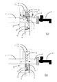
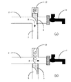
給湯システム用ヘッダー4は、図2及び図3に示すように、外形は十字状であり、給湯管2、返送管3、突起管7、給湯栓接続管8とが接続された構造となっていて、内部には、切替弁9、形状記憶合金からなるバネ10、閉塞部12が取り付けられている。突起管7は、バネ10と切替弁9を保持するためのもので、図2のX―X断面は図3に示すように、バネ保持部7aとなる円形状の部分に、湯水通路部7bとなる長方形の小片部分が付加された形状となっている。切替弁9は、湯水の経路を切替えるものであり、中心部には貫通孔11が穿設されている。貫通孔11は、湯水の通過路となるものであり、円錐台形状に形成されていて、入口(突起管7側)の断面積が、出口(返送管3側)の断面積よりも大きくなっている。また、閉塞部12は、返送管3に取り付けられていて、閉塞凸片13を有する構造となっている。また、給湯栓接続管8は、給湯システム用ヘッダー4と給湯栓5を接続する配管である。ここで、給湯栓5と循環ポンプ6との間は電気信号線(図示せず)で接続されていて、給湯栓5の開栓状態を示す電気信号が循環ポンプ6に伝達されるようになっている。
As shown in FIGS. 2 and 3, the hot water supply system header 4 has a cross shape and has a structure in which the hot
以下に、この給湯システム用ヘッダー4の動作について説明する。形状記憶合金からなるバネ10は、低温では縮んだ形状(図2(a)参照)となり、高温では伸びた形状(図2(b)参照)となるように形状記憶が設定されている。ここで、湯水が低温の状態では、図2(a)に示すようにバネ10は縮んで、切替弁9は、給湯栓接続管8を塞いだ状態となり、湯水を給湯管2から返送管3へと循環させるようになる。つまり、この状態で、使用者が給湯栓5を開栓すると、このことを示す電気信号が循環ポンプ6に伝達されて、運転を開始する。この結果、給湯管2の内部に滞留していた低温の湯水は、返送管3を通じて、貯湯タンク1の下部へと戻される。一方、貯湯タンク1の上部からは、高温の湯水が給湯管2へと供給される。このとき、給湯システム用ヘッダー4では、図2(a)に示すように、多くの湯水は給湯管2から返送管3へとAの方向に流れる。このとき、一部の湯水は、湯水通路部7b→バネ保持部7a→貫通孔11へとBからCの方向に流れる。このとき、湯水の通過路である貫通孔11は、入口の断面積が、出口の断面積よりも大きくなっているので、突起管7内部での湯水の流れがスムーズとなる。こうすることにより、形状記憶合金であるバネ10に直接に流動している湯水が接触することになる。したがって、給湯管2の湯水の温度が高温になると、これとほぼ同時に、バネ10の周辺の湯水も高温となる。この結果として、バネ10は伸びて、図2(b)に示す状態となる。こうなると、切替弁9は、返送管3を塞いだ状態となり、貯湯タンク1から供給される湯水は、給湯管2、給湯栓接続管8を経て、給湯栓5から吐出することになる。このとき、切替弁9の貫通孔11の出口を閉塞部12の閉塞凸片13が塞ぐようになっている。このために、給湯システム用ヘッダー4では、湯水は給湯管2から給湯栓接続管8へとDの方向のみに流れて、返送管3へと流れることはなくなる。このとき、循環ポンプ6の運転負荷が急激に増大する。ここで、循環ポンプ6は、一定以上の負荷になると、運転を停止するように予め設定されているので、湯水が給湯栓接続管8を介して給湯栓5に流れるようになった直後に循環ポンプ6は、自動的に運転を停止することになる。
Below, operation | movement of this header 4 for hot water supply systems is demonstrated. The shape memory is set so that the
ここで、使用者が給湯栓5を閉栓すると、貯湯タンク1からの湯水の供給が停止される。この後、時間が経過して、給湯管2の内部の湯水の温度が低下すると、形状記憶合金のバネ10は、図2(a)に示すように、縮んだ形状となって、切替弁9は、給湯栓接続管8を塞いだ状態となる。こうすることにより、この後再度、使用者が給湯栓5を開栓しても、給湯管2の内部の低温の湯水が、給湯栓5から提供されることはなくなる。
Here, when the user closes the
本実施形態の貯湯システム用ヘッダーは、貯湯タンクに接続して給湯端末に湯水を供給する給湯管と、湯水を前記貯湯タンクに返送する返送管とに接続して、給湯管内部の湯水の温度によって湯水の流れ方向を切替える切替弁を内蔵し、給湯管内部の湯水が低温の時は給湯管から返送管に湯水を返送して、給湯管内部の湯水が高温の時は給湯端末に湯水を供給する給湯システム用ヘッダーであって、切替え弁に接続して湯水の温度によって形状の変化する形状記憶合金からなるバネを有してなり、切替弁は湯水が低温の時は湯水の全部又は一部が通過する貫通孔を具備しているので、流動している湯水が直接にバネに接触することになる。したがって、簡易な構造で、温度変化の追従性の良好な掲示用記憶合金を用いた貯湯システム用ヘッダーを提供することができる。 The hot water storage system header of the present embodiment is connected to a hot water pipe connected to the hot water storage tank to supply hot water to the hot water supply terminal, and a return pipe returning the hot water to the hot water storage tank, and the temperature of the hot water inside the hot water supply pipe A switch valve that switches the flow direction of hot water is built in. When hot water in the hot water pipe is cold, hot water is returned from the hot water pipe to the return pipe, and when hot water in the hot water pipe is hot, hot water is supplied to the hot water terminal. A header for a hot water supply system to be supplied, comprising a spring made of a shape memory alloy which is connected to a switching valve and changes its shape depending on the temperature of the hot water. When the temperature of the hot water is low, the switching valve is all or one of hot water. Since the part has a through-hole through which the part passes, the flowing hot and cold water directly contacts the spring. Therefore, it is possible to provide a header for a hot water storage system using a memory alloy for posting having a simple structure and good followability to temperature changes.
また、切替弁の貫通孔は、給湯管側の湯水の入口の面積が返送管側の出口の湯水の出口の面積よりも大きいので、切替弁が給湯栓接続管を塞いだ状態では、突起管内部の湯水の流動がスムーズとなる。このために、バネに接触する湯水の流れが良好となり、湯水の温度が上昇した時の、切替弁の移動の追従性が向上する。 In addition, since the area of the hot water inlet on the hot water supply pipe side is larger than the area of the hot water outlet on the return pipe side, the through hole of the switching valve is a protruding pipe in a state where the switching valve closes the hot water tap connection pipe. The internal hot water flow is smooth. For this reason, the flow of the hot water in contact with the spring becomes good, and the follow-up performance of the movement of the switching valve when the temperature of the hot water rises is improved.
さらに、切替弁は、湯水が高温時には返送管側の貫通孔の出口を塞ぐ閉塞部を有するので、切替弁が返送管を塞いだ状態では、全ての湯水が給湯栓接続管側に、流れることになる。このために、給湯栓への湯水の供給量を増加させることができる。 Furthermore, since the switching valve has a closed portion that closes the outlet of the through hole on the return pipe side when hot water is hot, all hot water flows to the hot water tap connection pipe side when the switching valve closes the return pipe. become. For this reason, the amount of hot water supplied to the hot water tap can be increased.
1 貯湯タンク
2 給湯管
3 返送管
4 給湯システム用ヘッダー
5 給湯栓
6 循環ポンプ
7 突起管
7a バネ保持部
7b 湯水通路部
8 給湯栓接続管
9 切替弁
10 バネ(形状記憶合金)
11 貫通孔
12 閉塞部
13 閉塞凸片
DESCRIPTION OF
11 Through-
Claims (3)
前記切替え弁に接続して湯水の温度によって形状の変化する形状記憶合金からなるバネを有してなり、前記切替弁は湯水が低温の時は湯水の全部又は一部が通過する貫通孔を具備すること特徴とする給湯システム用ヘッダー。 Connected to a hot water supply pipe connected to the hot water storage tank to supply hot water to the hot water supply terminal and a return pipe to return the hot water to the hot water storage tank, a switching valve for switching the flow direction of the hot water depending on the temperature of the hot water inside the hot water supply pipe Built-in header for hot water supply system that returns hot water from the hot water supply pipe to the return pipe when the hot water inside the hot water supply pipe is cold, and supplies hot water to the hot water supply terminal when the hot water inside the hot water supply pipe is hot,
The switch valve has a spring made of a shape memory alloy whose shape changes depending on the temperature of hot water, and the switch valve has a through-hole through which all or part of the hot water passes when the temperature of the hot water is low. A header for a hot water supply system characterized by
The hot water supply system header according to claim 1 or 2, further comprising a blocking portion that closes an outlet of the through hole on the return pipe side when the hot water is at a high temperature.
Priority Applications (1)
| Application Number | Priority Date | Filing Date | Title |
|---|---|---|---|
| JP2004339658A JP2006145182A (en) | 2004-11-24 | 2004-11-24 | Header for hot water supply system |
Applications Claiming Priority (1)
| Application Number | Priority Date | Filing Date | Title |
|---|---|---|---|
| JP2004339658A JP2006145182A (en) | 2004-11-24 | 2004-11-24 | Header for hot water supply system |
Publications (1)
| Publication Number | Publication Date |
|---|---|
| JP2006145182A true JP2006145182A (en) | 2006-06-08 |
Family
ID=36625078
Family Applications (1)
| Application Number | Title | Priority Date | Filing Date |
|---|---|---|---|
| JP2004339658A Pending JP2006145182A (en) | 2004-11-24 | 2004-11-24 | Header for hot water supply system |
Country Status (1)
| Country | Link |
|---|---|
| JP (1) | JP2006145182A (en) |
Cited By (6)
| Publication number | Priority date | Publication date | Assignee | Title |
|---|---|---|---|---|
| JP2006283404A (en) * | 2005-03-31 | 2006-10-19 | Mym Corp | Joint for hot water supply, and hot water supply apparatus |
| JP2008039265A (en) * | 2006-08-04 | 2008-02-21 | Jfe Pipe Fitting Mfg Co Ltd | Circulation type hot water supply system |
| KR101381693B1 (en) * | 2012-12-20 | 2014-04-09 | 나동원 | Water faucet having water saving function |
| US8934763B2 (en) | 2012-04-20 | 2015-01-13 | Xylem Ip Holdings Llc | Water delivery system and method for making hot water available in a domestic hot water installation |
| US9027844B2 (en) | 2010-03-05 | 2015-05-12 | Xylem Ip Holdings Llc | Water delivery system and valve for a sink |
| CN112354801A (en) * | 2020-11-14 | 2021-02-12 | 安徽省富鑫雅光电科技有限公司 | LED lamp dispensing device |
-
2004
- 2004-11-24 JP JP2004339658A patent/JP2006145182A/en active Pending
Cited By (8)
| Publication number | Priority date | Publication date | Assignee | Title |
|---|---|---|---|---|
| JP2006283404A (en) * | 2005-03-31 | 2006-10-19 | Mym Corp | Joint for hot water supply, and hot water supply apparatus |
| JP4602820B2 (en) * | 2005-03-31 | 2010-12-22 | 株式会社ケーブイケー | Hot water supply joint and hot water supply device |
| JP2008039265A (en) * | 2006-08-04 | 2008-02-21 | Jfe Pipe Fitting Mfg Co Ltd | Circulation type hot water supply system |
| US9027844B2 (en) | 2010-03-05 | 2015-05-12 | Xylem Ip Holdings Llc | Water delivery system and valve for a sink |
| US8934763B2 (en) | 2012-04-20 | 2015-01-13 | Xylem Ip Holdings Llc | Water delivery system and method for making hot water available in a domestic hot water installation |
| KR101381693B1 (en) * | 2012-12-20 | 2014-04-09 | 나동원 | Water faucet having water saving function |
| CN112354801A (en) * | 2020-11-14 | 2021-02-12 | 安徽省富鑫雅光电科技有限公司 | LED lamp dispensing device |
| CN112354801B (en) * | 2020-11-14 | 2023-06-16 | 安徽省富鑫雅光电科技有限公司 | LED lamp adhesive deposite device |
Similar Documents
| Publication | Publication Date | Title |
|---|---|---|
| KR100788084B1 (en) | Fluid heating device and cleaning device using the same | |
| JP5277714B2 (en) | Water heater | |
| JP4876762B2 (en) | Heat pump type water heater | |
| JP2010091196A (en) | Water heater | |
| JP2007127318A (en) | Water heater | |
| JP2006145182A (en) | Header for hot water supply system | |
| WO2006074572A1 (en) | Hot and cold water dispenser and method of controlling same | |
| JP4715439B2 (en) | Heat pump water heater | |
| JP4936365B2 (en) | Water heater | |
| JP2007192458A (en) | Heat pump water heater | |
| JP2009222268A (en) | Storage water heater | |
| JP2009052798A (en) | Storage water heater with bath hot water supply function | |
| JP4375095B2 (en) | Heat pump water heater | |
| KR100614582B1 (en) | Method for controlling heating/hot-water of a boiler | |
| JP2011153772A (en) | Storage type hot water supply device | |
| JP5330988B2 (en) | Heat pump water heater | |
| JP5375728B2 (en) | Water heater | |
| JP2006010172A (en) | Hot water storage type hot water supply system | |
| JP2013217622A (en) | Storage water heater | |
| CN113389246B (en) | Water supply device and water supply system | |
| JP2008256322A (en) | Hot water storage type water heater | |
| JP7259593B2 (en) | Storage hot water heater | |
| JP4876840B2 (en) | Hot water system | |
| JP3938659B2 (en) | Hot spring equipment | |
| JP4935402B2 (en) | Heat pump water heater |