JP2006143255A - Assembling container - Google Patents
Assembling container Download PDFInfo
- Publication number
- JP2006143255A JP2006143255A JP2004334483A JP2004334483A JP2006143255A JP 2006143255 A JP2006143255 A JP 2006143255A JP 2004334483 A JP2004334483 A JP 2004334483A JP 2004334483 A JP2004334483 A JP 2004334483A JP 2006143255 A JP2006143255 A JP 2006143255A
- Authority
- JP
- Japan
- Prior art keywords
- container
- piece
- container body
- receiving piece
- receiving
- Prior art date
- Legal status (The legal status is an assumption and is not a legal conclusion. Google has not performed a legal analysis and makes no representation as to the accuracy of the status listed.)
- Pending
Links
Images


Abstract
Description
この発明は、粉粒体の薬品等を収納する組立容器、とくに大形の組立紙管に関する。 The present invention relates to an assembly container for storing powdery chemicals and the like, particularly to a large assembly paper tube.
従来から粉粒体の薬品等を収納する容器として、円筒形容器胴体の下端縁に円形の容器底面を取り付けたものがよく用いられている。しかし、容器胴体が円筒形では折りたたむことができず嵩張るため、内容物を収納していない場合にも保管や輸送のコストがかかる問題がある。 2. Description of the Related Art Conventionally, a container in which a circular container bottom is attached to a lower end edge of a cylindrical container body is often used as a container for storing powdery chemicals and the like. However, when the container body is cylindrical, the container body cannot be folded and is bulky. Therefore, there is a problem in that it costs storage and transportation even when the contents are not stored.
そこで特許文献1に示すように、頂部および底部が開口した筒状の箱本体、およびこの箱本体の底部に取着自在に取り付けられた底面材からなる容器本体ならびにこの箱本体の頂部に嵌合する蓋体から構成された組立型箱状容器であって、箱本体は水平断面の形状がN角形であり、N個の側胴面と、各側胴面の下端部から延び、内側に折り曲げられ、2つの側面と端面を有する舌片とから構成されており、底面材は、箱本体の断面形状と略相似形のN角形の平面形状を有する底面部本体と、この底面部本体の各辺から下方に延びる垂下片と、底面部本体の下面に貼り付けられ、底面部本体よりもわずかに外形の小さい板紙体から構成されており、組立型箱状容器の組立時、底面材の垂下片は箱本体の側胴面と舌片との間に形成された空間内に収納され、底面材の底面部本体は舌片の端面によって支持され、かつ、舌片の端部は底面材の垂下片と板紙体の端面との間に形成された空間内に収納されることを特徴とする組立型箱状容器が提案されている。 Therefore, as shown in Patent Document 1, a cylindrical box body whose top and bottom are open, a container body consisting of a bottom material detachably attached to the bottom of the box body, and the top of the box body are fitted. The box body has an N-shaped horizontal cross section, extends from the N side body surfaces and the lower end of each side body surface, and bends inward. And a tongue piece having two side surfaces and an end surface, and the bottom surface material is a bottom surface body having an N-square planar shape substantially similar to the cross-sectional shape of the box body, and each of the bottom surface body It consists of a hanging piece that extends downward from the side, and a paperboard body that is affixed to the bottom surface of the bottom surface body and has a slightly smaller outer shape than the bottom surface body. The piece is in the space formed between the side body surface of the box body and the tongue piece. The bottom surface body of the bottom surface material is supported by the end surface of the tongue piece, and the end portion of the tongue piece is accommodated in a space formed between the hanging piece of the bottom surface material and the end surface of the paperboard body. An assembly-type box-like container characterized by the above has been proposed.
このように構成することで、容器の組立および組立解除が容易となり、内容物を収納していない場合には、底面材を箱本体から取り外し、箱本体を折りたたむことができるため、嵩張らず保管や輸送のコストを低減することができる。 By configuring in this way, it is easy to assemble and disassemble the container, and when the contents are not stored, the bottom material can be removed from the box body and the box body can be folded. The cost of transportation can be reduced.
しかし上記した構成では、容器の組立を解除して折りたたむ場合、容器胴体と容器底部が分離するため一方を紛失しやすく、また、組立の際に別体のものを組み合わせる必要があるため手間がかかり作業能率が悪い問題がある。さらに、底面部本体の下面に板紙体を貼り付け、それによって箱本体の下端部から延びる舌片を支える構成のため、底面部が複雑となりコストがかかる問題がある。したがって、いまだ改善の余地が残されているといえる。 However, in the above-described configuration, when the container is assembled and folded, the container body and the bottom of the container are separated, so that it is easy to lose one of them, and it is necessary to combine separate parts when assembling. There is a problem of poor work efficiency. Furthermore, since the paperboard body is affixed to the lower surface of the bottom surface main body, thereby supporting the tongue piece extending from the lower end portion of the box main body, there is a problem that the bottom surface becomes complicated and costly. Therefore, it can be said that there is still room for improvement.
一方で作業能率等を考えて容器胴体と容器底部とを一体に形成することも考えられるが、この場合材料取りが悪く生産コストが高騰する問題を抱えている。
そこでこの発明の解決すべき課題は、容器胴体と容器底部とが通常の使用状態で分離せず組立容易であり、しかも簡単な構造で十分な強度を有する組立容器を低コストで提供することである。 Therefore, the problem to be solved by the present invention is to provide an assembly container which is easy to assemble without separating the container body and the container bottom in a normal use state, and which has a simple structure and sufficient strength at low cost. is there.
上記した課題を解決するため、この発明は組立容器について、上下端が開口した水平断面多角形の筒形容器胴体と、前記容器胴体の水平断面と相似形の多角形容器底部とからなり、容器胴体を構成する各側面の下端縁に内側上方に向けて受片を連設し、容器底部の多角形各辺のうち一以上の辺に下方に向けて垂下片を連設し、各受片と各受片に対向する各側面とから形成される隙間に垂下片を挿入することにより容器底部と容器胴体とを嵌合し、さらに一の受片の上端縁に外側下方に向けて係合片を連設し、前記受片と対向する垂下片の下端縁に内側上方に向けて係合片を連設し、両係合片の係合により容器底部と容器胴体とを常態で分離しないように構成したのである。 In order to solve the above-described problems, the present invention relates to an assembly container comprising a cylindrical container body having a horizontal cross-section with open upper and lower ends, and a polygonal container bottom having a shape similar to the horizontal cross-section of the container body. Receiving pieces are continuously provided on the lower end edge of each side surface constituting the body toward the inside and upward, and hanging pieces are provided continuously on one or more sides of the polygonal sides of the container bottom portion. The bottom of the container and the body of the container are inserted into a gap formed by each of the receiving pieces and the side surfaces facing the receiving pieces. A piece is continuously provided, and an engaging piece is continuously provided inward and upward at the lower end edge of the hanging piece facing the receiving piece, and the container bottom and the container body are not normally separated by the engagement of both engaging pieces. It was configured as follows.
また、この発明は組立容器について、上下端が開口した水平断面多角形の筒形容器胴体と、前記容器胴体の水平断面と相似形の多角形容器底部とからなり、容器胴体を構成する各側面の下端縁に内側上方に向けて受片を連設し、容器底部の多角形各辺の一以上の辺に下方に向けて垂下片を連設し、各受片と各受片に対向する各側面とから形成される隙間に垂下片を挿入することにより容器底部と容器胴体とを嵌合し、一の垂下片を各受片と各受片に対向する各側面とから形成される隙間内に固着する構成としたのである。 Further, the present invention relates to an assembled container, which is composed of a cylindrical container body having a horizontal cross section whose upper and lower ends are open, and a polygonal container bottom having a shape similar to the horizontal cross section of the container body, and each side surface constituting the container body A receiving piece is connected to the lower end edge of the container inward and upward, and a hanging piece is connected downward to one or more sides of each polygon side of the container, facing each receiving piece and each receiving piece. A gap formed by inserting a hanging piece into a gap formed from each side surface to fit the container bottom and the container body, and forming one hanging piece from each receiving piece and each side face facing each receiving piece. The structure is fixed inside.
なお、上記した受片については、隣接する側縁同士を一体に連結するのが好ましい。 In addition, about an above-described receiving piece, it is preferable to connect adjacent side edges integrally.
一の受片の上端縁に外側下方に向けて係合片を連設し、前記受片と対向する垂下片の下端縁に内側上方に向けて係合片を連設し、両係合片の係合により容器底部と容器胴体とを連結することにより、容器胴体と容器底部が通常の使用状態において分離することがないため、一方を紛失することはなく、また、組立も一挙動でできるため作業能率が向上する。さらに、容器底部と容器胴体を別体で製造するため、一体に成形する場合に比べて材料取りにおけるロスが少なく、生産コストを低廉に抑えることができる。 An engagement piece is continuously provided on the upper end edge of one receiving piece toward the outside and downward, and an engagement piece is provided on the lower end edge of the hanging piece facing the receiving piece and directed upward on the inside. By connecting the container bottom and the container body by the engagement of the container body, the container body and the container bottom part are not separated in a normal use state, so that one of them is not lost and the assembly can be performed in one behavior. Therefore, work efficiency is improved. Furthermore, since the container bottom and the container body are manufactured separately, there is less loss in material removal than in the case of forming them integrally, and the production cost can be reduced.
一の垂下片を各受片と各受片に対向する各側面とから形成される隙間内に固着することにより、容器胴体と容器底部が分離することがないため、一方を紛失することはなく、また、組立も一挙動でできるため作業能率が向上する。さらに、容器底部と容器胴体を別体で製造するため、一体に成形する場合に比べて材料取りにおけるロスが少なく、生産コストを低廉に抑えることができる。 By fixing one hanging piece in the gap formed by each receiving piece and each side surface facing each receiving piece, the container body and the bottom of the container will not be separated, so one will not be lost In addition, since the assembly can be done with one behavior, the work efficiency is improved. Furthermore, since the container bottom and the container body are manufactured separately, there is less loss in material removal than in the case of forming them integrally, and the production cost can be reduced.
また、受片の隣接する側縁同士を一体に連結することにより、各受片が容器材料の持つ弾性に起因して対向する各側面から離間する方向へ戻るのを防止することができ、保形性を持たせることができる。したがって、組立の際に手間取らず作業能率がさらに向上する。また、受片と各受片に対向する各側面とから形成される隙間に垂下片を挿入する際に、緩みが生じることなく容器底部と容器胴体とを強固に結合させることができるため、組立容器の強度を増すことができる。さらに、受片に保形性を持たせているため、従来のように容器底部の裏側にパットを貼り付けるなどして受片のはずれを防止する必要がない。そのため容器底部の構造が簡単で済み、コストダウンを図ることができる。 In addition, by connecting the adjacent side edges of the receiving pieces together, it is possible to prevent the receiving pieces from returning in a direction away from the opposing side surfaces due to the elasticity of the container material. It can have shape. Therefore, the work efficiency is further improved without taking time and effort during assembly. In addition, when inserting the hanging piece into the gap formed by the receiving piece and each side surface facing each receiving piece, the container bottom and the container body can be firmly coupled without causing loosening. The strength of the container can be increased. Further, since the shape of the receiving piece is given, it is not necessary to prevent the receiving piece from being detached by pasting a pad on the back side of the bottom of the container as in the prior art. Therefore, the structure of the container bottom is simple and the cost can be reduced.
以下、図面を参照しつつこの発明の実施形態について説明する。 Embodiments of the present invention will be described below with reference to the drawings.
図1のように、この発明の実施形態にかかる組立容器10は、側面胴体を構成する容器胴体30と、底面を構成する容器底部40と、上端の開口をふさぐ容器蓋20とからなる。組立容器10は平面視正八角形であり、容器胴体30は8つの側面31からなる筒状体である。
As shown in FIG. 1, an
図2は、容器底部40の展開図を表す。図のように、正八角形の底面41の8つの辺のうち1つ置きの対向する4辺に垂下片42が連設されており、さらに1つの垂下片42の端縁には係合片43が連設されている。底面41と垂下片42との境界には、折れ線44が形成され、垂下片42と係合片43の境界には折れ線45が形成されている。
FIG. 2 shows a development view of the
容器底部40は、図3のように、底面41の四辺から垂下片42を折れ線44に沿って下方に折り曲げ、さらに、係合片43を垂下片42の端縁から折れ線45に沿って内側上方に折り曲げて組み立てられる。
As shown in FIG. 3, the
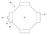
図4は、容器胴体30の展開図を表す。図のように、容器胴体30は、短冊状でほぼ同形の8つの側面31の側縁同士を連設し、その1側縁に接続しろ32を連設し、さらに側面31の下端縁には受片33が連設され、一の受片の下端縁には係合片34が連設された構成となっている。ここで、隣接する受片33同士は一体となっている。
FIG. 4 is a development view of the
側面31同士および側面31と接続しろ32および受片33同士の境界には、折れ線35が形成され、側面31と受片33との境界には、折れ線36が形成される。折れ線35と折れ線36との交差点は、折り曲げを容易にするためにひし形あるいは将棋の駒形の折曲孔37が設けられている。また、受辺33と係合片34との境界には、折れ線38が形成されている。
A
前記側面31上端中央には、組立容器10を把持するための角丸6角形の把持孔31aが組み立てた時に対向するように2つ設けられている。さらに、8つの側面31のうち1つ置きの4つの側面31について、下端中央に側面31と受片33とを接着するための接着部材39が貼付されている。なお、接着部材39は、両面に接着剤を塗布等した厚みのあるボール紙等から形成されている。厚みは10mm位が最適である。
Two rounded
容器胴体30は、以下の手順で作成される。まず、図5(a)のように、係合片34を折れ線38に沿って受片33の接着部材39貼付側の面に向けて折り返す。次に受片33を折れ線36に沿って、側面31の接着部材39貼付側の面に折り返し、接着部材39に貼付する。
The
つぎに、図5(b)のように、側面31を折れ線35に沿って折り返された受片33が内側となるように折り返し、最後に、接続しろ32と他端の側面31とを接着剤等により貼付する。このようにして図5(c)のように、平面視正八角形の筒状容器胴体30が組み立てられる。
Next, as shown in FIG. 5 (b), the
なお、上記したように、折れ線35と折れ線36との交差点には折曲孔37が設けられているため、組立の際の折り曲げが容易に行える。またここで、接着部材39を貼付しない側面31と、対向する受片33、およびその両側の接着部材39の貼付による接着により閉じられた側面31、受片33とから図5(d)のように、ポケット33aが形成される。
As described above, since the
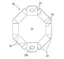
図6は、容器蓋20の展開図を表す。図のように、正八角形の頂面21の8つの辺に側片22が連設されており、組み立てたとき対向する側片22のうち1組には、角丸6角形の把持孔22aが設けられている。また、側片22の隣接する側縁の一方には、接続しろ23が連設されている。頂面21と側片22との境界は折れ線24を形成し、側片22と接続しろ23の境界は折れ線25を形成する。把持孔22aは、後述するように、容器胴体30の側面31の把持孔31aと重ね合わせ貫通孔を形成するため、同形にしてある。
FIG. 6 is a development view of the
容器蓋20は、図7のように、折れ線25で接続しろ23を折り曲げ、頂面21から8つの側片22を折れ線24に沿って下方に折り曲げ、側片22の各側縁同士を当接させた状態で接続しろ23により固着することにより組み立てられる。
As shown in FIG. 7, the
上記のようにして組み立てた容器蓋20、容器胴体30、容器底部40から、さらに組立容器10を組み立てる。
The
まず図8(a)のように、筒状容器胴体30の開口した上端から、容器底部40を挿入する。容器底部40には上述したように、底面41の4つの辺から下方に向けて4つの垂下片42が連設されているところ、これを容器胴体30の4つのポケット33aに挿入する。
First, as shown in FIG. 8A, the container bottom 40 is inserted from the opened upper end of the
ここで図8(b)のように、係合片43が端縁に連設された垂下片42を、係合片34が端縁に連設された受片33と、受片33に対向する側面31とから形成されるポケット33aに挿入すると両係合片34、43は係合するため容器胴体30と容器底部40とは結合され分離しがたくなる。
Here, as shown in FIG. 8 (b), the hanging
次に図8(c)のように、筒状容器胴体30の開口した上端に、容器蓋20を被せると容器蓋20の頂面21の裏面が容器胴体30の上端に当接し係止される。この際に、容器胴体30の側面31に設けられた把持孔31aと、容器蓋20の側片22に設けられた把持孔22aを重ね合わせると貫通孔が形成されるため、容器を把持しやすく運ぶ際の利便性が向上する。このようにして容器蓋20と容器胴体30と容器底部40とは組み合わされ、図1のような組立容器10が完成する。
Next, as shown in FIG. 8C, when the
組立容器10の組立を解除するには、組立と逆に容器蓋20を容器胴体30上端から取り外した後、容器胴体30のポケット33aから容器底部40の係合片43が連設されていない3つの垂下片42を抜き取り容器胴体30を折りたたむ。このとき係合片34を有する垂下片42と係合片43を有するポケット33aとが、係合片34、43同士の係合により結合しているため、容器胴体30と容器底部40とは分離せず一体になっている。
In order to release the assembly of the
以上のように、係合片34、43同士の係合により、容器底部40と容器胴体30とを通常の使用状態で一体にすることができる。そのため、組立や組立解除の際に容器胴体30と容器底部40が分離することがない。従って、一方を紛失するおそれはなく、また、組立および組立解除もワンタッチでできるため作業能率が向上する。また、容器底部40と容器胴体30を別体で製造するため、一体に成形する場合に比べて材料取りにおけるロスが少なく生産コストを低廉に抑えることができる。
As described above, the container bottom 40 and the
また、隣接する受片33同士は一体となっているため、各受片33が組立容器10の材料の持つ弾性に起因して、対向する各側面31から離間する方向へ戻るのを防止することができ、保形性を持たせることができる。従って、組立の際に手間取らず作業能率がさらに向上する。また、受片33と各受片33に対向する各側面31とから形成されるポケット33aに垂下片42を挿入する際に、緩みが生じることなく容器底部40と容器胴体30とを強固に結合させることができるため、組立容器10の強度を増すことができる。さらに、受片33に保形性を持たせているため、従来のように容器底部40の裏側にパットを貼り付けるなどして受片33のはずれを防止する必要がない。そのため容器底部40の構造が簡単で済み、コストダウンを図ることができる。
Further, since the adjacent receiving
なお、この実施の形態では、容器胴体30と容器底部40との結合を係合片34、43同士の係合により実現したが、これに限られず、容器胴体30の4つのポケット33aに挿入した4つの垂下片42のうちの1つを、ポケット33a内に接着剤等で固着することによっても同様の効果を奏することができる。
In this embodiment, the connection between the
上記した組立容器10の材質はボール紙、厚紙、合成紙などさまざまなものが考えられる。また、上述した実施形態では、組立容器を平面視正八角形のものとしたが勿論これに限られず他の平面視多角形容器にも適用できる。
Various materials such as cardboard, cardboard, and synthetic paper can be considered for the
10 組立容器
20 容器蓋
21 頂面
22 側片
22a 把持孔
23 接続しろ
24 折れ線
25 折れ線
30 容器胴体
31 側面
31a 把持孔
32 接続しろ
33 受片
33a ポケット
34 係合片
35 折れ線
36 折れ線
37 折曲孔
38 折れ線
39 接着部材
40 容器底部
41 底面
42 垂下片
43 係合片
44 折れ線
45 折れ線
DESCRIPTION OF
Claims (3)
Priority Applications (1)
| Application Number | Priority Date | Filing Date | Title |
|---|---|---|---|
| JP2004334483A JP2006143255A (en) | 2004-11-18 | 2004-11-18 | Assembling container |
Applications Claiming Priority (1)
| Application Number | Priority Date | Filing Date | Title |
|---|---|---|---|
| JP2004334483A JP2006143255A (en) | 2004-11-18 | 2004-11-18 | Assembling container |
Publications (2)
| Publication Number | Publication Date |
|---|---|
| JP2006143255A true JP2006143255A (en) | 2006-06-08 |
| JP2006143255A5 JP2006143255A5 (en) | 2007-12-27 |
Family
ID=36623385
Family Applications (1)
| Application Number | Title | Priority Date | Filing Date |
|---|---|---|---|
| JP2004334483A Pending JP2006143255A (en) | 2004-11-18 | 2004-11-18 | Assembling container |
Country Status (1)
| Country | Link |
|---|---|
| JP (1) | JP2006143255A (en) |
Cited By (3)
| Publication number | Priority date | Publication date | Assignee | Title |
|---|---|---|---|---|
| KR20220147279A (en) * | 2021-04-27 | 2022-11-03 | 주식회사 현준산업 | Case Assembly |
| KR20230068890A (en) * | 2021-11-11 | 2023-05-18 | 에코라이프패키징 주식회사 | Packaging Box for Bottle |
| KR20230068891A (en) * | 2021-11-11 | 2023-05-18 | 에코라이프패키징 주식회사 | Packaging Box for Bottle |
Citations (3)
| Publication number | Priority date | Publication date | Assignee | Title |
|---|---|---|---|---|
| JPS5184823U (en) * | 1974-12-25 | 1976-07-07 | ||
| JPH0880935A (en) * | 1994-07-27 | 1996-03-26 | Sonoco Prod Co | Vessel |
| JPH114921A (en) * | 1997-06-13 | 1999-01-12 | Kawano:Kk | Golf club head for iron |
-
2004
- 2004-11-18 JP JP2004334483A patent/JP2006143255A/en active Pending
Patent Citations (3)
| Publication number | Priority date | Publication date | Assignee | Title |
|---|---|---|---|---|
| JPS5184823U (en) * | 1974-12-25 | 1976-07-07 | ||
| JPH0880935A (en) * | 1994-07-27 | 1996-03-26 | Sonoco Prod Co | Vessel |
| JPH114921A (en) * | 1997-06-13 | 1999-01-12 | Kawano:Kk | Golf club head for iron |
Cited By (6)
| Publication number | Priority date | Publication date | Assignee | Title |
|---|---|---|---|---|
| KR20220147279A (en) * | 2021-04-27 | 2022-11-03 | 주식회사 현준산업 | Case Assembly |
| KR102535977B1 (en) | 2021-04-27 | 2023-05-26 | 주식회사 현준산업 | Case Assembly |
| KR20230068890A (en) * | 2021-11-11 | 2023-05-18 | 에코라이프패키징 주식회사 | Packaging Box for Bottle |
| KR20230068891A (en) * | 2021-11-11 | 2023-05-18 | 에코라이프패키징 주식회사 | Packaging Box for Bottle |
| KR102615280B1 (en) * | 2021-11-11 | 2023-12-19 | 에코라이프패키징 주식회사 | Packaging Box for Bottle |
| KR102644449B1 (en) * | 2021-11-11 | 2024-03-08 | 에코라이프패키징 주식회사 | Packaging Box for Bottle |
Similar Documents
| Publication | Publication Date | Title |
|---|---|---|
| US11001406B2 (en) | Foldable box having adhesive wing portions | |
| CA2541182A1 (en) | Improved display ready container | |
| KR200484072Y1 (en) | Foldable paper cup | |
| JP5508065B2 (en) | Paper container | |
| JP2006143255A (en) | Assembling container | |
| JP6890961B2 (en) | Blanks and cartons | |
| JP5507333B2 (en) | Easy deployment container | |
| KR20100109830A (en) | Packing box integrated with handle | |
| KR20090011014U (en) | Packing box | |
| JP4687580B2 (en) | Repack blister | |
| JP2006199371A (en) | Corrugated cardboard packing box | |
| JP6288994B2 (en) | Assembled container and assembled trash box composed of the container | |
| KR200357454Y1 (en) | A Box Structuer For Containning The Food | |
| KR200440979Y1 (en) | The Packaging for a Box | |
| JP6773405B2 (en) | Packaging box | |
| JP7346814B2 (en) | packaging container | |
| JP3229162U (en) | Box sheet | |
| JP7297635B2 (en) | packaging box | |
| JPS62500861A (en) | Clips for securing overlapping parts of cardboard boxes or similar items | |
| CN211483766U (en) | Product display box | |
| JP6245810B2 (en) | Packaging container | |
| JP6886891B2 (en) | Collective carrier for cans | |
| JP3133835U (en) | Breathable wooden container | |
| KR102074220B1 (en) | Integrated waterproof packing structure | |
| JP2023153580A (en) | Packaging structure for transportation |
Legal Events
| Date | Code | Title | Description |
|---|---|---|---|
| A521 | Written amendment |
Free format text: JAPANESE INTERMEDIATE CODE: A523 Effective date: 20071113 |
|
| A621 | Written request for application examination |
Free format text: JAPANESE INTERMEDIATE CODE: A621 Effective date: 20071113 |
|
| A977 | Report on retrieval |
Free format text: JAPANESE INTERMEDIATE CODE: A971007 Effective date: 20100907 |
|
| A131 | Notification of reasons for refusal |
Effective date: 20101026 Free format text: JAPANESE INTERMEDIATE CODE: A131 |
|
| A02 | Decision of refusal |
Effective date: 20110301 Free format text: JAPANESE INTERMEDIATE CODE: A02 |