JP2006142995A - Two-wheel vehicle with pusher hand rod - Google Patents
Two-wheel vehicle with pusher hand rod Download PDFInfo
- Publication number
- JP2006142995A JP2006142995A JP2004336019A JP2004336019A JP2006142995A JP 2006142995 A JP2006142995 A JP 2006142995A JP 2004336019 A JP2004336019 A JP 2004336019A JP 2004336019 A JP2004336019 A JP 2004336019A JP 2006142995 A JP2006142995 A JP 2006142995A
- Authority
- JP
- Japan
- Prior art keywords
- pusher bar
- brake
- lever
- holding cylinder
- pusher
- Prior art date
- Legal status (The legal status is an assumption and is not a legal conclusion. Google has not performed a legal analysis and makes no representation as to the accuracy of the status listed.)
- Granted
Links
- 210000000078 claw Anatomy 0.000 description 9
- 125000006850 spacer group Chemical group 0.000 description 3
- 239000002184 metal Substances 0.000 description 2
- 238000005452 bending Methods 0.000 description 1
- 230000002093 peripheral effect Effects 0.000 description 1
Images


Landscapes
- Carriages For Children, Sleds, And Other Hand-Operated Vehicles (AREA)
Abstract
Description
本発明は、着座シートの後方から立上がる押手棒にブレーキレバーを設けた押手棒付き二輪車に関するものである。 The present invention relates to a two-wheeled vehicle with a pusher bar in which a brake lever is provided on a pusher bar that rises from behind a seating seat.
子供あるいは幼児が二輪車に乗り始める場合、通常は運転技術が未熟であったり運転に十分慣れていないため安定して走行できないことが多い。この場合に補助者が運転を助けるため操向ハンドルを横から支えたり、子供(あるいは幼児)の背中を手で押したり支えたりすることがある。 When a child or an infant starts to ride a motorcycle, the driving skill is usually inexperienced or the driver is not sufficiently used to drive, and often cannot run stably. In this case, the assistant may support the steering handle from the side to assist driving, or may push and support the back of the child (or infant) by hand.
しかしブレーキレバーは操向ハンドルに取付けられ、この操向ハンドルは子供(幼児)が手で握っているため、補助者は横からこのブレーキレバーを操作することは不可能あるいは極めて困難である。このため緊急の場合に補助者はブレーキを操作できず、子供(幼児)の背中を引いたり押える程度の不十分な対応しかできなかった。また特に幼児では足踏みペダルの踏み込みが円滑にできないことがあり、このような時には補助者が幼児の背中を押したり操向ハンドルを引っ張る必要が生じ、円滑に走行できないという問題があった。 However, since the brake lever is attached to the steering handle, and the steering handle is held by a child (infant), it is impossible or extremely difficult for an assistant to operate the brake lever from the side. For this reason, in the case of an emergency, the assistant could not operate the brakes, and was only able to handle the child (infant) with an insufficient response to pulling or pushing. In particular, an infant may not be able to smoothly step on the foot pedal. In such a case, the assistant needs to push the infant's back or pull the steering handle, which causes a problem that the driver cannot run smoothly.
そこでこのような二輪車に押手棒を取付け、この押手棒に別のブレーキレバーを取付けることが提案された(特許文献1)。この既提案のものは、後輪の両側方から上方へ延出する門形の押手杆を車体フレームに立設し、この押手杆に後輪のブレーキレバーを取付けたものである。そしてこのブレーキレバーと後輪のドラムブレーキとをワイヤでつなぐものである。 Therefore, it has been proposed to attach a pusher bar to such a motorcycle and attach another brake lever to the pusher bar (Patent Document 1). In this proposal, a portal-type pusher bar extending upward from both sides of the rear wheel is erected on the body frame, and a brake lever for the rear wheel is attached to the pusher bar. The brake lever and the rear wheel drum brake are connected by a wire.
この既提案のものでは操向ハンドルの左グリップに元々取付けたブレーキレバーとブレーキドラムとをつなぐワイヤのブレーキレバー側の端を外して、この端を押手杆のブレーキレバーにつなぎ変えるものである。従って子供(幼児)が運転に習熟して押手杆が不用になった時には、この押手杆を取外してワイヤの端を操向ハンドルのブレーキレバーに接続し直すものである。 In this proposal, the brake lever side end of the wire connecting the brake lever and the brake drum originally attached to the left grip of the steering handle is removed, and this end is connected to the brake lever of the push rod. Therefore, when the child (infant) becomes familiar with driving and the handle bar becomes unnecessary, the handle bar is removed and the end of the wire is reconnected to the brake lever of the steering handle.
この既提案のものは、後輪のドラムブレーキのワイヤを操向ハンドルの(左側の)ブレーキレバーから外して押手杆のブレーキレバーにつなぎ直すものであるため、この状態では子供(幼児)が後ブレーキを操作できず、前ブレーキのみしか操作できない。このため適正な運転操作に習熟しにくかったり、慣れるのに時間がかかるという問題がある。 The proposed one is that the rear wheel drum brake wire is removed from the steering handle (left side) brake lever and reconnected to the push lever brake lever. The brake cannot be operated and only the front brake can be operated. For this reason, there is a problem that it is difficult to master proper driving operation and it takes time to get used to it.
また押手棒を着脱する時にはワイヤの端を押手杆のブレーキレバーと操向ハンドルのブレーキレバーとの間でつなぎ変える必要が生じ、その作業が極めて面倒でもあった。 In addition, when attaching and detaching the push bar, it is necessary to change the end of the wire between the brake lever of the push rod and the brake lever of the steering handle, which is very troublesome.
この発明はこのような事情に鑑みなされたものであり、操向ハンドルの後輪ブレーキレバーも使用可能にすると共に、車体を支えまた車体を押すための押手棒を、ブレーキワイヤのつなぎ変えなどの面倒な作業をすることなく車体に対して容易に着脱可能にする押手棒付き二輪車を提供することを目的とする。 The present invention has been made in view of such circumstances, and the rear wheel brake lever of the steering handle can be used, and a pusher bar for supporting the vehicle body and pushing the vehicle body can be changed by connecting the brake wire. An object of the present invention is to provide a two-wheeled vehicle with a pusher bar that can be easily attached to and detached from the vehicle body without troublesome work.
この発明によればこの目的は、前・後輪の間に配設された着座シートの後方から斜上後方へ延出する押手棒を備える押手棒付き二輪車において、前記着座シートと後輪との間から斜上後方に向かって開口するように車体フレームに固着された押手棒保持筒と、この押手棒保持筒に上方から着脱可能に装着される押手棒と、前記後輪の外周に接触・離隔可能なブレーキシューが取付けられ車体幅方向の支軸によって前記押手棒保持筒付近に揺動自在に取付けられたブレーキシューレバーと、前記押手棒のグリップ部に設けたブレーキレバーと前記ブレーキシューレバーとを連動させるブレーキ連動機構とを備え、前記ブレーキ連動機構は前記ブレーキシューレバーに係脱可能としたことを特徴とする押手棒付き二輪車、により達成される。 According to the present invention, the object of the present invention is to provide a two-wheeled vehicle with a pusher bar including a pusher bar that extends obliquely upward and rearward from the rear of the seating seat disposed between the front and rear wheels. A pusher bar holding cylinder fixed to the vehicle body frame so as to open obliquely upward and backward from the middle, a pusher bar detachably attached to the pusher bar holding cylinder from above, and an outer periphery of the rear wheel A brake shoe lever to which a separable brake shoe is attached and which is swingably attached to the vicinity of the pusher bar holding cylinder by a support shaft in the vehicle body width direction, a brake lever provided at a grip part of the pusher bar, and the brake shoe lever And a brake interlocking mechanism that interlocks with the brake shoe lever, and the brake interlocking mechanism can be engaged with and disengaged from the brake shoe lever.
押手棒は、車体側の押手棒保持筒に上方から着脱可能であり、後輪の外周に接触・離隔するブレーキシューを有するブレーキシューレバーを押手棒保持筒付近に車体幅方向の支軸により揺動自在に取付け、押手棒のブレーキレバーとこのブレーキシューレバーとをブレーキ連動機構により係脱可能に連動させたから、押手棒を取外す時にブレーキシューレバーからブレーキレバーを解放することにより押手棒の着脱が容易に行える。またブレーキシューレバーは操向ハンドルのブレーキレバーで操作する後ブレーキとは別に設けられているから、子供(幼児)は自分で後ブレーキを操作することが可能である。このため子供(幼児)は速やかに運転操作に習熟できる。 The pusher bar can be attached to and removed from the pusher bar holding cylinder on the vehicle body side from above, and a brake shoe lever having a brake shoe that contacts and separates from the outer periphery of the rear wheel is rocked by a support shaft in the vehicle body width direction near the pusher bar holding cylinder. Because the brake lever of the pusher bar and this brake shoe lever are detachably linked by the brake interlocking mechanism, the pusher bar can be attached and detached by releasing the brake lever from the brake shoe lever when removing the pusher bar. Easy to do. Since the brake shoe lever is provided separately from the rear brake operated by the brake lever of the steering handle, the child (infant) can operate the rear brake by himself. For this reason, the child (infant) can quickly master driving operation.
ブレーキシューレバーは押手棒保持筒に取付けるのが望ましいが、この付近の車体フレームの他の部位に取付けてもよい。ブレーキ連動機構は押手棒に設けておき、このブレーキ連動機構の一部の構成部材が、押手棒の着脱時にブレーキシューレバーに係脱する構造とするのが望ましい。 The brake shoe lever is preferably attached to the push rod holding cylinder, but may be attached to other parts of the body frame in the vicinity thereof. It is desirable that the brake interlocking mechanism is provided on the pusher bar, and that some components of the brake interlocking mechanism are engaged with and disengaged from the brake shoe lever when the pusher bar is attached and detached.
後輪の一側方(または両側方)に補助輪を設けた二輪車であれば、車体は左右方向に倒れにくくなり、押手棒は左右方向の傾き姿勢の修正に過大な注意を払うことなく主として前後方向の走行に集中して操作できるので、操作性が向上する(請求項2)。 If the motorcycle has an auxiliary wheel on one side (or both sides) of the rear wheel, the vehicle body will not fall easily in the left-right direction, and the pusher bar will mainly be used without paying too much attention to correcting the left-right tilt posture. Since the operation can be performed by concentrating on the traveling in the front-rear direction, the operability is improved (claim 2).
ブレーキ連動機構は、押手棒を形成するパイプの中に通し上端をブレーキレバーにつないだワイヤと、押手棒の下部に装着されこのワイヤにより上下動するリフタとを備え、このリフタを直接ブレーキシューレバーに係脱可能に構成すれば、ブレーキ連動機構は押手棒側に全て取付けられ、小型化に適する(請求項3)。リフタは押手棒の外周に摺動する略筒状とし、このリフタに設けたフランジをブレーキシューレバーに係脱可能にすることができる(請求項4)。リフタは他の構造のものも可能である。例えば押手棒のパイプ壁を貫通して突出するピンをブレーキレバーにより上下動可能とし、このピンをリフタとしてブレーキシューレバーに係脱可能にしてもよい。 The brake interlocking mechanism has a wire that passes through the pipe that forms the pusher bar and the upper end is connected to the brake lever, and a lifter that is attached to the lower part of the pusher bar and moves up and down by this wire. If it is configured to be able to be engaged and disengaged, the brake interlocking mechanism is all attached to the push bar side, and is suitable for downsizing (Claim 3). The lifter has a substantially cylindrical shape that slides on the outer periphery of the pusher bar, and a flange provided on the lifter can be engaged with and disengaged from the brake shoe lever. The lifter can have other structures. For example, a pin protruding through the pipe wall of the push bar can be moved up and down by a brake lever, and this pin can be used as a lifter to be engaged with and disengaged from the brake shoe lever.
略筒状のリフタを用いる場合には、フランジの一部を切欠いておき、この切欠きがブレーキシューレバーに係合しない位置にくるようにリフタを回転させることにより、押手棒を抜き取れるようにすることが可能である(請求項4)。押手棒を左右の所定角度範囲内で回動自在とし、この回動を操向前輪に伝えることにより、押手棒で操舵可能にすることができる(請求項5)。この場合の操舵連動機構は、車体フレームのメインパイプに通したロッドにより押手棒と操向軸とを連動させるように構成することができる(請求項6)。このようにすれば車体フレーム内に操舵連動機構を収納できるので、車体外部の突出物が少なくなり、子供(幼児)の衣服を引っ掛けて衣服を汚すおそれが無くなる。 When using a substantially cylindrical lifter, cut out a part of the flange and rotate the lifter so that the notch is in a position where it does not engage the brake shoe lever. (Claim 4). By allowing the pusher bar to turn within a predetermined range of right and left and transmitting this rotation to the front steering wheel, the pusher bar can be steered (claim 5). In this case, the steering interlocking mechanism can be configured such that the pusher bar and the steering shaft are interlocked with each other through a rod passed through the main pipe of the vehicle body frame. In this way, the steering interlock mechanism can be housed in the vehicle body frame, so that the number of protrusions outside the vehicle body is reduced, and there is no possibility that the child's (infant) 's clothes will be hooked and soiled.
押手棒の下部やブレーキシューレバー付近をカバーで覆っておけば、これらに衣服を引っ掛けたり衣服を汚すおそれが無くなる。またこのカバーに後輪の泥除けを一体に形成しておくことも可能であり、この場合には部品点数の減少に適する(請求項7)。 If the lower part of the push bar and the vicinity of the brake shoe lever are covered with a cover, there is no possibility of hooking clothes on them or making them dirty. It is also possible to integrally form a mudguard for the rear wheel on this cover, which is suitable for reducing the number of parts (claim 7).
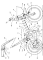
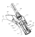
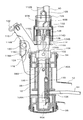
図1は本発明の一実施例の側面図、図2は操向軸保持筒の側断面図、図3は押手棒保持筒の非ブレーキ時の側断面図、図4は同じくブレーキ時の側断面図、図5は押手棒に設けたブレーキレバーのブレーキ時を示す側面図、図6はブレーキ連動機構を説明するための側断面図、図7はブレーキシューレバーとリフタを示す図である。なお図3,4,5,7は各構成部品を重ねて表したものであり、正確な断面図ではない。 FIG. 1 is a side view of an embodiment of the present invention, FIG. 2 is a side sectional view of a steering shaft holding cylinder, FIG. 3 is a side sectional view of a push rod holding cylinder when not braked, and FIG. FIG. 5 is a side view showing a brake lever provided on a pusher bar during braking, FIG. 6 is a side sectional view for explaining a brake interlocking mechanism, and FIG. 7 is a view showing a brake shoe lever and a lifter. 3, 4, 5, and 7 show the respective component parts in an overlapping manner, and are not accurate sectional views.
図1において符号10は車体フレームであり、前後方向のパイプからなるメインパイプ12と、その前端に固着された操向軸保持筒14と、メインパイプ12の後端に固着された押手棒保持筒16と、メインパイプ12の後部を上下に貫通する直線上に位置するシートチューブ18およびボトムブラケット支持パイプ20と、ボトムブラケット22から後方へのびる左右一対のチェーンステー24と、このチューンステー24の後端とシートチューブ18とをつなぐ左右一対のバックステー26とを持つ。
In FIG. 1,
操向軸保持筒14には操向前輪28が左右へ操舵可能に保持される。チューンステー24とバックステー26の結合部に固着された左右一対のエンドプレートには、後輪30が保持される。またエンドプレートには左右一対の補助輪32が保持されている。これらの補助輪32は後輪30の両側方で路面に接触し、車体が左右へ倒れるのを防ぐ。
A
後輪30の左側面にはバンドブレーキからなる後ブレーキ34が組付けられている。ボトムブラケット22には、左右一対のクランクペダル36が固定されたクランク軸が軸支され、このクランク軸の右端に固定されたクランクギヤ(図示せず)と、後輪30の右側面に固定されたスプロケット(図示せず)とに、チェーン(図示せず)が巻掛けられている。これらクランクギヤ、スプロケット、チェーンはチェーンケース38でカバーされている。
A
40は着座シートであり、このシート40を保持するシートポスト(図示せず)はシートチューブ18に挿入され、シートの高さを調節可能に固定される。シートチューブ18はボトムブラケット支持パイプ20よりも小径であり、シートポストはメインチューブ12内を貫通してこのボトムブラケット支持パイプ20内に進入可能である。なおシートポストの左右両側にはメインチューブ12の内面との間に間隙が形成され、この間隙には後記する操舵連動機構のロッド64が通る。
42は前輪28を保持する前フォーク、44は操向ハンドルである。前記操向軸保持筒14には、図2に示すように、上下の開口にブッシュ46,48が嵌合され、両ブッシュ46,48の間に内筒50が回動自在に保持されている。この内筒50には、前フォーク42と一体の操向軸52が下方から挿入され、この操向軸52と内筒50とがピン54により結合されて一体に回動する。操向軸52はパイプで作られ、上のブッシュ46を貫通して上方へ突出している。操向軸52の上端部には軸方向に長いスリット(すり割り)52Aが形成され、上方から操向ハンドル44のハンドルポスト44Aが挿入される。そして操向軸52の上端を周方向にクランプ56で締付けることにより、ハンドルポスト44Aは操向軸52に固定される。
操向軸52の下部にはフランジ状のリング58が固着され、このリング58が下のブッシュ48に下方から摺動可能に当接し、前輪28の荷重をこのブッシュ48で支持している。操向軸保持筒14にはメインパイプ12の内側に向って開く窓60が形成される一方、内筒50にはこの窓60に臨む高さに円形のカム板62が固着されている。このカム板62には、操舵連動機構の2本のロッド64(一方のみ図示)の前端が係合している。すなわちこのロッド64の前端は下方へほぼ直角に折曲されこの折曲部がカム板62の係合孔62Aに上方から係入する。
A flange-
なおカム板62の2つの係合孔62Aは、前輪28の直進位置で内筒50の中心を通る車幅方向の直線上に位置する。これらロッド64は、上のブッシュ46に係止したスぺーサ66により、カム板62の係合孔から上方へ脱出するのを防止される。操向軸52の上部にはブラケット70が固定され、前フォーク42の中央を前後に貫通するセンターボルト68にはブラケット72が固定され、これらのブラケット70,72に荷かご74が取付けられている。なおセンターボルト68にはキャリパーブレーキからなる前ブレーキ76が保持されている。
The two
操向バーハンドル44の左右のグリップ78に設けたブレーキレバー80(図1に右側のみ図示)は、それぞれ後ブレーキ34および前ブレーキ76に接続される。すなわち左のブレーキレバーはワイヤ82によって後ブレーキ34に連結され、右のブレーキレバー80はワイヤ(図示せず)により前ブレーキ76に連結されている。操向軸保持筒14の上端および下端にはキャップ84,86が取付けられている。また前フォーク42には前輪28の泥よけ88が取付けられている。
Brake levers 80 (only shown on the right side in FIG. 1) provided on the left and
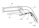
90は押手棒であり、金属パイプの上部を鈍角に折曲してここをグリップ92としたものである。この押手棒90の下部は押手棒保持筒16に挿抜可能である。すなわち押手棒保持筒16には、上下の開口を塞ぐ上下のブッシュ94,96が嵌合され、これらのブッシュ94,96によって内筒98が回動自在に保持されている。そして押手棒90は上のブッシュ94を貫通してこの内筒98の内側を通って、その下端が下のブッシュ96に支持されている。
内筒98の上部には上方に開く一対の係合孔98Aが形成され、これらの係合孔98Aに押手棒90を横断するピン100の両端が係入している。このため押手棒90と内筒98とは一体に回動する。上のブッシュ94には上方から円板状の蓋板102が嵌合される一方、押手棒90にはこの蓋板102にガイドされてブッシュ94に上方から当接するリング104が固定されている。リング104は押手棒90の挿入時にブッシュ94に当接し、押手棒90を上下方向に位置決めするストッパとなる。
A pair of
内筒98にはメインパイプ12に臨む高さにカム板106が固着されている。カム板106には、グリップ92を後方に向けた時(直進位置)に、内筒98の中心を車体幅方向に通る直線上に位置する一対の係合孔106Aが形成されている。前記ロッド64の後端は下方へほぼ直角に折曲されて、これらの係合孔106Aに上方から係入している。なお上のブッシュ94には内筒98の外側を下降するスぺーサ108が取付けられ、このスぺーサ108はロッド64が係合孔106Aから上方へ脱出するのを防いでいる。
A
この実施例では、押手棒保持筒16と操向軸保持筒14とにそれぞれ設けた内筒98,50が、一対のロッド64で連結されて同期して回動する。従って押手棒90の回動により操向軸52が連動して操舵可能である。すなわち内筒98,50がロッド64,カム板106,62などによって、押手棒90の回動を前輪28に伝える操舵連動機構が形成される。この操舵連動機構については同一出願人による出願(特願2004−271937)に詳細に説明されているので、これを参照することによりその構成は一層明確になる。
In this embodiment,
次に押手棒90から操作するブレーキ装置を説明する。押手棒90のグリップ92にはブレーキレバー110が取付けられ、このブレーキレバー110の操作は、押手棒90のパイプ内に通されたワイヤ112とリフタ114とを含むブレーキ連動機構により後記ブレーキシューレバー116に伝えられる。
Next, a brake device operated from the
ブレーキシューレバー116は、押手棒保持筒16の上部に車体幅方向に間隔をあけて溶接された一対のブレーキブラケット118,118に車体幅方向の支軸120によって揺動自在に取付けられている。ブレーキシューレバー116は、図6,7に示すように、支軸120と平行な底部116Aの両側を起立させてこの突起部116B,116Bを側面視(図6)で略J字状に形成したものである。この起立部116Bとブレーキブラケット118には、支軸120に保持したトーションばね124の両端が係止され、ブレーキシューレバー116に図6で時計方向(後記ブレーキシュー122が後輪30から離れる方向)への復帰習性を付与する。ブレーキシューレバー116の底部116Aは、押手棒保持筒16の上面に嵌合したブッシュ94の上面に当接してブレーキシューレバー116の時計方向への復帰位置を決めるストッパともなっている。
The
ブレーキシューレバー116の後部(起立部116Bの後部)は後輪30の上方へ延出し、これら両起立部116B,116Bの後端は後輪30の外周に対向するブレーキシュー122で結合されている(図1,6)。ブレーキシューレバー116の前部、すなわち起立部116B,116Bの前部は押手棒90の両側に延出し、それらの前端は上方に湾曲すると共にその上端が押手棒90側にほぼ水平に折曲された係合爪116C,116Cとなっている。これらの係合爪116C,116Cはリフタ114に係脱するものである。
The rear part of the brake shoe lever 116 (the rear part of the
次にブレーキ連動機構をブレーキシューレバー116と係脱可能にする機構を説明する。前記ワイヤ112は公知のボーデンワイヤであり、アウタワイヤ112Aの中でインナワイヤ112Bが往復動するものである。アウタワイヤ112Aの上端はブレーキレバー110のブラケット110Aに係止され、アウタワイヤ112Aの下端は押手棒90内を横断するアウタ受け部材126(図3)に係止される。インナワイヤ112Bはこのアウタ受け部材126を貫通してフック128の上端に係止されている。
Next, a mechanism that enables the brake interlocking mechanism to be engaged with and disengaged from the
フック128は細長い板金部材の途中をクランク状に折曲したものである。すなわち押手棒90に前記リング104を固定するピン104Aや、押手棒90を内筒98に固定するピン100(図6)との干渉を逃げるようにフック128は折曲されている。フック128の下端と、押手棒90の下端に設けた爪90Aとの間には引張りコイルばね130が掛け渡されている。このためフック128およびインナワイヤ112Bには常に引張り力が作用している。
The
押手棒90には、前記ブレーキシューレバー116の係合爪116Cより十分高い位置に、軸方向に長い長孔90B,90Bが軸中心に対して対称に形成されている。フック128には、これら長孔90B,90Bを通りかつリフタ114を貫通して両外側へ突出する1本のリフタピン132が係止されている。このためフック128とリフタピン132とリフタ114とは一体となって上下動する。
In the
リフタ114は押手棒90の外周で摺動するパイプ状であり、その下縁は拡径したフランジ114Aとなっている。このフランジ114Aには、図7に示すように軸対称の位置に約90°の切欠き114B,114Bが形成されている。リフタ114には前記リフタピン132が係合する周方向に長い孔114Cが形成されている(図7(C))。このためリフタ114はこの長い孔114Cの範囲内で周方向に回動可能である。
The
134はリフタキャップである。リフタキャップ134は下部が拡径した段付きのパイプ状であり、その内面にはリフタピン132に上方から係合する段部134Aが形成されている。リフタキャップ134の下部開口内面には、ロックリング134Bがロック可能である。リフタ114の外周にはこのロックリング134Bとリフタピン132との間に、リフタばね136が縮装され、ロックリング134Bはピン138によってリフタ114に係止されている。すなわちリフタ114の中心軸に対して対称な位置には、軸方向へ長い孔114D,114D(一方のみ図示)が形成され、ロックリング134Bの内周面に突設したピン138がこれらの長い孔114Dに係入している。
このようにリフタばね136を圧縮した状態でロックリング134Bをリフタ114に装着し、リフタキャップ134を上から被せてその下部をロックリング134Bにロックする。この結果ばね136により押下げられたロックリング134Bのピン138は長い孔114Dの下縁に係止し、ロックリング134Bと一体化したリフタキャップ134は図6の状態で静止する。この状態ではリフタ114のフランジ114Aは、図7(B)に示すようにブレーキシューレバー116に係合する。従ってブレーキレバー110を握ればワイヤ112によりフック128が上昇し、このフック128と共にリフタピン132、リフタ114が上昇する。このためブレーキシューレバー116が支軸120を中心として図4で反時計方向に回動し、ブレーキシュー122が後輪30の外周に押付けられ、ブレーキが効くことになる(図4)。
The
ブレーキレバー110を解放すれば、フック128はコイルばね130により下方へ復帰する。このためリフタ114が下降し、ブレーキシューレバー116はトーションばね124により復帰し、ブレーキシュー122が後輪から離れる(図3,6)。
When the
押手棒90を左右に回動すれば、ピン100で係合した内筒98が一体に回動する。この内筒98の回転はカム板106,ロッド64を介して、操向軸保持筒14内のカム板62,内筒50に伝えられる。内筒50の回動はピン54により操向軸52に伝えられ、前輪28および操向ハンドル44が左右に回動する。
When the
なおリフタ114のフランジ114Aは、図7(B)に示すように前輪28の直進位置でフランジ114Aの範囲の中央付近がブレーキシューレバー116の爪116Cに係合し、前輪28の操舵範囲内では爪116Cはフランジ114Aと係合可能となるようにフランジ114Aの周方向の長さと位置が設定されている。このため押手棒90を操舵時に回動する範囲内ではフランジ114Aが爪116Cから外れることはなく、ブレーキレバー110を引けばブレーキシューレバー116が揺動してブレーキシュー122が後輪30に押圧される。
As shown in FIG. 7B, the
押手棒90を抜く時には、リフタキャップ134を図7(B)で反時計方向に回動し、リフタ114のフランジ114Aをブレーキシューレバー116の爪116Cから外れる位置、すなわち図7(A)に示す位置にする。この状態ではフランジ114Aが爪116Cに当たることなく、押手棒90を上方へ抜くことができる。従って子供(幼児)が自転車に慣れれば、この押手棒90を抜いて、一人で乗れるようにすることができる。
When the
なおリフタキャップ134の段部134Aに、図7(B)の位置でリフタピン132が上方へ落ち込む凹部を形成しておけば、リフタキャップ134を図7(B)の位置に安定させることができる。
In addition, if the recessed part into which the
押手棒90の下部、ブレーキシューレバー116付近は、カバー140で覆われている。このカバー140は、図3,4に示すように前部が押手棒保持筒16の上部を前から囲み、後部が後輪30の上方に延出して後輪30の泥除けとなっている。このカバー140は前端を押手棒保持筒16の前面に設けた係合孔140Aに係止し、内面に突設したリブをブレーキブラケット118の後端面118Aにビス140Bによってビス止めすることにより取付けられる。
The lower part of the
10 車体フレーム
12 メインパイプ
16 押手棒保持筒
28 前輪
30 後輪
32 補助輪
64 ロッド
90 押手棒
92 グリップ
110 ブレーキレバー
112 ワイヤ
114 リフタ
114A フランジ
114B 切欠き
116 ブレーキシューレバー
140 カバー
DESCRIPTION OF
Claims (7)
前記着座シートと後輪との間から斜上後方に向かって開口するように車体フレームに固着された押手棒保持筒と、
この押手棒保持筒に上方から着脱可能に装着される押手棒と、
前記後輪の外周に接触・離隔可能なブレーキシューが取付けられ車体幅方向の支軸によって前記押手棒保持筒付近に揺動自在に取付けられたブレーキシューレバーと、
前記押手棒のグリップ部に設けたブレーキレバーと前記ブレーキシューレバーとを連動させるブレーキ連動機構とを備え、
前記ブレーキ連動機構は前記ブレーキシューレバーに係脱可能としたことを特徴とする押手棒付き二輪車。 In a two-wheeled vehicle with a pusher bar provided with a pusher bar that extends diagonally upward and backward from the rear of the seating seat disposed between the front and rear wheels,
A push bar holding cylinder fixed to the vehicle body frame so as to open obliquely upward and rearward from between the seating seat and the rear wheel;
A pusher bar detachably attached to the pusher bar holding cylinder from above;
A brake shoe lever attached to the outer periphery of the rear wheel and swingably attached to the vicinity of the pusher bar holding cylinder by a support shaft in a vehicle body width direction;
A brake interlock mechanism that interlocks the brake lever provided on the grip portion of the push bar and the brake shoe lever;
The two-wheeled vehicle with a pusher bar, wherein the brake interlocking mechanism can be engaged with and disengaged from the brake shoe lever.
操舵連動機構は前記メインパイプ内に挿通されたロッドによって押手棒の回動を前輪に伝える請求項5の押手棒付き二輪車。 The vehicle body frame includes a main pipe made of a substantially straight pipe, and a steering shaft holding cylinder and a push bar holding cylinder fixed to the front end and the rear end of the main pipe,
The two-wheeled vehicle with a pusher bar according to claim 5, wherein the steering interlocking mechanism transmits the rotation of the pusher bar to the front wheel by a rod inserted into the main pipe.
The two-wheeled vehicle with a pusher bar according to claim 1, further comprising a cover that covers a lower part of the pusher bar and a brake shoe lever, and a mudguard for a rear wheel is integrally formed on the cover.
Priority Applications (1)
| Application Number | Priority Date | Filing Date | Title |
|---|---|---|---|
| JP2004336019A JP4111945B2 (en) | 2004-11-19 | 2004-11-19 | Motorcycle with push bar |
Applications Claiming Priority (1)
| Application Number | Priority Date | Filing Date | Title |
|---|---|---|---|
| JP2004336019A JP4111945B2 (en) | 2004-11-19 | 2004-11-19 | Motorcycle with push bar |
Publications (2)
| Publication Number | Publication Date |
|---|---|
| JP2006142995A true JP2006142995A (en) | 2006-06-08 |
| JP4111945B2 JP4111945B2 (en) | 2008-07-02 |
Family
ID=36623176
Family Applications (1)
| Application Number | Title | Priority Date | Filing Date |
|---|---|---|---|
| JP2004336019A Active JP4111945B2 (en) | 2004-11-19 | 2004-11-19 | Motorcycle with push bar |
Country Status (1)
| Country | Link |
|---|---|
| JP (1) | JP4111945B2 (en) |
Cited By (4)
| Publication number | Priority date | Publication date | Assignee | Title |
|---|---|---|---|---|
| JP2010006134A (en) * | 2008-06-24 | 2010-01-14 | Oaks Co Ltd | Auxiliary steering device of bicycle |
| EP2209697A1 (en) * | 2007-09-14 | 2010-07-28 | Soma Cycle, Inc. | Convertible stroller-cycle |
| JP2011201500A (en) * | 2010-03-26 | 2011-10-13 | Aidesu Kk | Vehicle for baby |
| CN106347527A (en) * | 2016-11-09 | 2017-01-25 | 衢州市中安建筑工程设备有限公司 | Electric bicycle anti-falling auxiliary device driven by push rod motor |
-
2004
- 2004-11-19 JP JP2004336019A patent/JP4111945B2/en active Active
Cited By (6)
| Publication number | Priority date | Publication date | Assignee | Title |
|---|---|---|---|---|
| EP2209697A1 (en) * | 2007-09-14 | 2010-07-28 | Soma Cycle, Inc. | Convertible stroller-cycle |
| EP2209697A4 (en) * | 2007-09-14 | 2010-12-22 | Soma Cycle Inc | Convertible stroller-cycle |
| JP2010006134A (en) * | 2008-06-24 | 2010-01-14 | Oaks Co Ltd | Auxiliary steering device of bicycle |
| JP2011201500A (en) * | 2010-03-26 | 2011-10-13 | Aidesu Kk | Vehicle for baby |
| CN106347527A (en) * | 2016-11-09 | 2017-01-25 | 衢州市中安建筑工程设备有限公司 | Electric bicycle anti-falling auxiliary device driven by push rod motor |
| CN106347527B (en) * | 2016-11-09 | 2022-03-11 | 吴仁渭 | Electric vehicle anti-falling auxiliary device driven by push rod motor |
Also Published As
| Publication number | Publication date |
|---|---|
| JP4111945B2 (en) | 2008-07-02 |
Similar Documents
| Publication | Publication Date | Title |
|---|---|---|
| US8459679B2 (en) | Pivot mechanism for scooters, tricycles and the like | |
| US20100032925A1 (en) | Convertible stroller-cycle | |
| CN108528626B (en) | Bicycle operating device | |
| CN108528625B (en) | Bicycle operating device | |
| JP3205733B2 (en) | Bicycle frame | |
| TWI641524B (en) | Bicycle control device | |
| TWI718333B (en) | Bicycle operating device | |
| JP4111945B2 (en) | Motorcycle with push bar | |
| JP6392029B2 (en) | Tricycle | |
| CN108025720B (en) | Saddle-ride type vehicle | |
| JP5205326B2 (en) | Saddle riding | |
| JPH11129953A (en) | Child seat for bicycle | |
| JP2004136713A (en) | Tricycle for child | |
| JP2013043461A (en) | Key cylinder holding structure and method for saddle-riding type vehicle | |
| JP7011566B2 (en) | Lever support structure | |
| JP4664886B2 (en) | Brake / stand interlocking device for motorcycles | |
| JP3033744U (en) | Braking operating device for bar handle | |
| JP7336410B2 (en) | Bicycle stands and bicycles equipped with them | |
| US11780527B2 (en) | Straddle-type vehicle | |
| JP3087745U (en) | Children's vehicles | |
| TWI286111B (en) | Detachable front fork assembly of bike | |
| JP4220438B2 (en) | Steering device for guardian of infant vehicle and infant vehicle equipped with this device | |
| JP2024056502A (en) | Children's bicycle | |
| JP3830127B2 (en) | Electric assist bicycle | |
| JP5442374B2 (en) | Motorcycle |
Legal Events
| Date | Code | Title | Description |
|---|---|---|---|
| A131 | Notification of reasons for refusal |
Free format text: JAPANESE INTERMEDIATE CODE: A131 Effective date: 20061013 |
|
| A977 | Report on retrieval |
Free format text: JAPANESE INTERMEDIATE CODE: A971007 Effective date: 20061016 |
|
| A521 | Request for written amendment filed |
Free format text: JAPANESE INTERMEDIATE CODE: A523 Effective date: 20061212 |
|
| A131 | Notification of reasons for refusal |
Free format text: JAPANESE INTERMEDIATE CODE: A131 Effective date: 20071023 |
|
| A521 | Request for written amendment filed |
Free format text: JAPANESE INTERMEDIATE CODE: A523 Effective date: 20071105 |
|
| TRDD | Decision of grant or rejection written | ||
| A01 | Written decision to grant a patent or to grant a registration (utility model) |
Free format text: JAPANESE INTERMEDIATE CODE: A01 Effective date: 20080326 |
|
| A61 | First payment of annual fees (during grant procedure) |
Free format text: JAPANESE INTERMEDIATE CODE: A61 Effective date: 20080408 |
|
| R150 | Certificate of patent or registration of utility model |
Free format text: JAPANESE INTERMEDIATE CODE: R150 Ref document number: 4111945 Country of ref document: JP Free format text: JAPANESE INTERMEDIATE CODE: R150 |
|
| FPAY | Renewal fee payment (event date is renewal date of database) |
Free format text: PAYMENT UNTIL: 20110418 Year of fee payment: 3 |
|
| R250 | Receipt of annual fees |
Free format text: JAPANESE INTERMEDIATE CODE: R250 |
|
| FPAY | Renewal fee payment (event date is renewal date of database) |
Free format text: PAYMENT UNTIL: 20130418 Year of fee payment: 5 |
|
| R250 | Receipt of annual fees |
Free format text: JAPANESE INTERMEDIATE CODE: R250 |
|
| FPAY | Renewal fee payment (event date is renewal date of database) |
Free format text: PAYMENT UNTIL: 20130418 Year of fee payment: 5 |
|
| FPAY | Renewal fee payment (event date is renewal date of database) |
Free format text: PAYMENT UNTIL: 20140418 Year of fee payment: 6 |
|
| R250 | Receipt of annual fees |
Free format text: JAPANESE INTERMEDIATE CODE: R250 |
|
| R250 | Receipt of annual fees |
Free format text: JAPANESE INTERMEDIATE CODE: R250 |
|
| R250 | Receipt of annual fees |
Free format text: JAPANESE INTERMEDIATE CODE: R250 |
|
| R250 | Receipt of annual fees |
Free format text: JAPANESE INTERMEDIATE CODE: R250 |
|
| R250 | Receipt of annual fees |
Free format text: JAPANESE INTERMEDIATE CODE: R250 |
|
| R250 | Receipt of annual fees |
Free format text: JAPANESE INTERMEDIATE CODE: R250 |
|
| R250 | Receipt of annual fees |
Free format text: JAPANESE INTERMEDIATE CODE: R250 |
|
| R250 | Receipt of annual fees |
Free format text: JAPANESE INTERMEDIATE CODE: R250 |
|
| R250 | Receipt of annual fees |
Free format text: JAPANESE INTERMEDIATE CODE: R250 |
|
| R250 | Receipt of annual fees |
Free format text: JAPANESE INTERMEDIATE CODE: R250 |
|
| R250 | Receipt of annual fees |
Free format text: JAPANESE INTERMEDIATE CODE: R250 |
|
| R250 | Receipt of annual fees |
Free format text: JAPANESE INTERMEDIATE CODE: R250 |