JP2006141114A - Controller for air conditioner - Google Patents
Controller for air conditioner Download PDFInfo
- Publication number
- JP2006141114A JP2006141114A JP2004327426A JP2004327426A JP2006141114A JP 2006141114 A JP2006141114 A JP 2006141114A JP 2004327426 A JP2004327426 A JP 2004327426A JP 2004327426 A JP2004327426 A JP 2004327426A JP 2006141114 A JP2006141114 A JP 2006141114A
- Authority
- JP
- Japan
- Prior art keywords
- phase
- power supply
- phase power
- line
- wire
- Prior art date
- Legal status (The legal status is an assumption and is not a legal conclusion. Google has not performed a legal analysis and makes no representation as to the accuracy of the status listed.)
- Pending
Links
Images


Abstract
Description
本発明は三相四線式交流電源を用いた空気調和機の欠相検出技術に関するものである。 The present invention relates to a phase loss detection technique for an air conditioner using a three-phase four-wire AC power source.
従来、この種の空気調和機は三相電源の各々の線間電圧を入力し、電源の相間電圧に同期したパルスを発生させ、そのパルスの途絶えを検出するなどの工夫をしている(例えば、特許文献1参照)。 Conventionally, this type of air conditioner has been devised to input each line voltage of a three-phase power supply, generate a pulse synchronized with the phase voltage of the power supply, and detect the interruption of the pulse (for example, , See Patent Document 1).
図3は、特許文献1に記載された従来の欠相検出技術を示すものである。図3に示すように、三相三線式の三相電源21から接続端子22を介して、線間電圧をパルス発生回路25に接続している。前記パルス発生回路25は信号処理回路26と接続し開閉Ry23と表示手段29から構成されている。この構成から、パルス発生回路25は三相電源21の線間電圧を入力しているため、相間電圧に同期したパルスを発生させることができる。そのことにより、特定の相のパルスの途絶えなどを検出し、信号処理回路26で開閉Ry23の通電遮断と表示手段29での異常表示をするものである。
しかしながら、前記従来の構成では、日本国内の三相三線式交流電源での線間電圧(AC200V)を検出制御することに対して有効ではあるが、欧州や中国などの三相四線式交流電源では線間電圧がAC380V〜415Vとなるため、パルス発生回路25に使用する部品は高耐圧部品が必要になり、部品の大型化に加え、コストアップにつながる課題を有していた。
However, although the conventional configuration is effective for detecting and controlling the line voltage (AC200V) in a three-phase three-wire AC power source in Japan, a three-phase four-wire AC power source such as Europe and China. In this case, the line voltage becomes AC 380V to 415V, so that the components used in the
本発明は、前記従来の課題を解決するもので、三相四線式交流電源における欠相検出を簡単な構成で実現するインバータ空気調和機の制御装置を提供することを目的とする。 SUMMARY OF THE INVENTION The present invention solves the above-described conventional problems, and an object thereof is to provide an inverter air conditioner control device that realizes phase loss detection in a three-phase four-wire AC power supply with a simple configuration.
前記従来の課題を解決するために、本発明の空気調和機の制御装置は、三相四線式交流電源によって動作するインバータで駆動される空気調和機において、前記空気調和機内部には三相四線式交流電源の三相線と、中性点電源線とを具備し、R相電源線と中性点電源線には制御手段、S相電源線には電流検出手段、T相電源線と中性点電源線には第1の三相電源開閉手段の開閉部を介して第2の三相電源開閉手段の励磁コイル部に接続し、前記R相電源線・S相電源線・T相電源線には、第2の三相電源開閉手段の開閉部・平滑手段・インバータ駆動手段・圧縮機と接続し、前記電流検出手段は第1の通信手段と接続し、制御手段とインバータ駆動手段は第2の通信手段で接続して構成し、少なくとも三相四線式の電源線で、どの相が欠相しても、第2の三相電源開閉手段の開閉部を開動作させる制御としたものである。 In order to solve the conventional problems, an air conditioner control device according to the present invention is an air conditioner driven by an inverter that is operated by a three-phase four-wire AC power source, and the air conditioner has a three-phase inside. It has a three-phase line of a four-wire AC power source and a neutral point power line, the control means for the R phase power line and the neutral point power line, the current detection means for the S phase power line, and the T phase power line The neutral point power line is connected to the exciting coil section of the second three-phase power switching means via the switching section of the first three-phase power switching means, and the R-phase power line, S-phase power line, T The phase power line is connected to the opening / closing part, smoothing means, inverter driving means, compressor of the second three-phase power switching means, the current detecting means is connected to the first communication means, and the control means and inverter drive The means is configured by connecting with the second communication means, and at least a three-phase four-wire power line, which phase is missing. Also, in which the opening and closing portion of the second three-phase power supply switching means as a control for opening operation.
これによって、三相四線式交流電源の中性点電源線を利用すると共にS相のみ電流を検出することから、簡単な構成で欠相検出が可能になる。 As a result, the neutral point power supply line of the three-phase four-wire AC power supply is used and the current is detected only in the S phase, so that the phase loss can be detected with a simple configuration.
本発明の空気調和機の制御装置は、三相四線式交流電源ならではの中性点電源線を利用し、中性点電源線とR相とT相の電圧検出方式に加え、S相の電流検出方式のため、三相線間での検出方式と比較して、低電圧(線間電圧の1/√3)になるため、小型部品の採
用が可能でかつ構成も簡素なため、安価に欠相検出が可能になる。
The control device for an air conditioner of the present invention uses a neutral point power line unique to a three-phase four-wire AC power source, and in addition to the neutral point power line, the R phase and the T phase voltage detection method, Low current (1 / √3 of line voltage) because of current detection method, compared to detection method between three-phase lines, so small parts can be used and the configuration is simple, so it is inexpensive It is possible to detect phase loss.
本発明の空気調和機の制御装置は、三相四線式交流電源によって動作するインバータで駆動される空気調和機において、前記空気調和機内部には三相四線式交流電源の三相線(以下、各々R相電源線・S相電源線・T相電源線と称す)と、中性点電源線とを具備し、R相電源線と中性点電源線には制御手段、S相電源線には電流検出手段、T相電源線と中性点電源線には第1の三相電源開閉手段の開閉部を介して第2の三相電源開閉手段の励磁コイル部に接続し、前記R相電源線・S相電源線・T相電源線には、三相電源開閉手段2の開閉部・平滑手段・インバータ駆動手段・圧縮機と接続し、前記電流検出手段は第1の通信手段と接続し、制御手段とインバータ駆動手段は第2の通信手段で接続して構成し、少なくとも三相四線式の電源線で、どの相が欠相しても、第2の三相電源開閉手段の開閉部を開動作させるため簡単な構成で安価に欠相検出が可能になる。 The air conditioner control device according to the present invention is an air conditioner driven by an inverter that is operated by a three-phase four-wire AC power supply, and the three-phase wire of the three-phase four-wire AC power supply ( (Hereinafter referred to as R-phase power supply line, S-phase power supply line, and T-phase power supply line) and a neutral point power supply line. The current detection means is connected to the line, and the T-phase power supply line and the neutral point power supply line are connected to the excitation coil part of the second three-phase power supply switching means via the opening / closing part of the first three-phase power supply switch means, The R-phase power supply line, S-phase power supply line, and T-phase power supply line are connected to the opening / closing section, smoothing means, inverter driving means, and compressor of the three-phase power supply switching means 2, and the current detection means is the first communication means And the control means and the inverter driving means are connected by the second communication means, and at least a three-phase four-wire power line , Which phase is also phase loss, allowing low cost open phase detection with a simple configuration for the opening and closing unit is opened operation of the second three-phase power supply switching means.
以下、本発明の実施の形態について、図面を参照しながら説明する。なお、この実施の形態によって本発明が限定されるものではない。 Hereinafter, embodiments of the present invention will be described with reference to the drawings. Note that the present invention is not limited to the embodiments.
(実施の形態1)
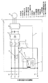
図1は、本発明の実施の形態1における制御装置のブロック図、図2はその制御動作を示すフローチャートである。
(Embodiment 1)
FIG. 1 is a block diagram of a control device according to Embodiment 1 of the present invention, and FIG. 2 is a flowchart showing its control operation.
図1において、1は制御装置、2は制御手段、3は電流検出手段、4は第1の通信手段で前記制御手段2と前記電流検出手段3とに接続している。10は第1の3相電源開閉手段、11は第2の3相電源開閉手段であり本願では開閉リレーで表現しており、前記第1の3相電源開閉手段10の励磁コイル部は、前記制御手段2の内部に具備されている。さらに前記第1の3相電源開閉手段10の接点部は第2の3相電源開閉手段11の励磁コイル部とT相電源線9tに接続している。前記第2の3相電源開閉手段11の接点部は3接点用であり、その接点は電源側にはR相電源線9r、S相電源線9s、T相電源線9tと接続し、負荷側には平滑手段7、インバータ駆動手段6、圧縮機8の順に接続している。5は第2の通信手段で前記制御手段2と前記インバータ駆動手段6に接続している。9nは中性点電源線である。前記制御手段2は前記R相電源線9rと前記中性点電源線9nと接続し、前記電流検出手段3は前記S相電源線9sを貫通させ、前記第2の3相電源開閉手段11の接点に接続している。前記第2の3相電源開閉手段11の励磁コイル部は直列に接続された状態で前記T相電源線9tと前記中性点電源線9nとに接続している。
In FIG. 1, 1 is a control device, 2 is control means, 3 is current detection means, and 4 is a first communication means connected to the control means 2 and the current detection means 3.
以上のように構成された制御装置について、以下に図2のフローチャートも用いてその動作、作用を説明する。 The operation and action of the control device configured as described above will be described below with reference to the flowchart of FIG.
まず、三相四線式交流電源が空気調和機の制御装置1に正常に接続された時、前記制御手段2と前記電流検出手段3とに通電される(S1)(S2)。その後、第1の通信手段4で正常と判断(S3)した場合、前記第1の3相電源開閉手段10の励磁コイル部に励磁され、前記第1の3相電源開閉手段10の接点部は閉動作(S4)する。その信号を受けて、前記第2の3相電源開閉手段11の励磁コイル部に励磁され、前記第2の3相電源開閉手段11の接点部は閉動作(S5)する。 First, when the three-phase four-wire AC power supply is normally connected to the control device 1 of the air conditioner, the control means 2 and the current detection means 3 are energized (S1) (S2). After that, when the first communication means 4 determines that it is normal (S3), it is excited by the exciting coil part of the first three-phase power supply switching means 10, and the contact part of the first three-phase power supply switching means 10 is The closing operation is performed (S4). Upon receiving the signal, the excitation coil portion of the second three-phase power supply switching means 11 is excited, and the contact portion of the second three-phase power supply switching means 11 is closed (S5).
次に、三相四線式交流電源が空気調和機の制御装置1に正常に接続されず、いずれかの相が欠相した時であるが、R相欠相時は、前記制御手段2に通電されず(S6)、前記第1の3相電源開閉手段10の励磁コイル部に励磁されることは有り得ない。よって、前記第1の3相電源開閉手段10の接点部は開動作(S9)する。したがって、前記第2の3相電源開閉手段11の励磁コイル部に励磁されることもなく、前記第2の3相電源開閉手
段11の接点部は開動作(S10)する。S相欠相時は、前記電流検出手段3に電流が流れず(S7)、第1の通信手段4で異常と判断(S8)する。この場合前記第1の3相電源開閉手段10の励磁コイル部に励磁はしない。よって、前記第1の3相電源開閉手段10の接点部は開動作(S9)する。したがって、前記第2の3相電源開閉手段11の励磁コイル部に励磁されることもなく、前記第2の3相電源開閉手段11の接点部は開動作(S10)する。T及びN相欠相時は、前記第2の3相電源開閉手段11の励磁コイル部に励磁する電源そのものが遮断されているため励磁コイル部に励磁することは有り得ない。よって、前記第2の3相電源開閉手段11の接点部は開動作(S10)する。
Next, when the three-phase four-wire AC power supply is not normally connected to the control device 1 of the air conditioner and one of the phases is lost, the control means 2 It is impossible to energize the exciting coil portion of the first three-phase power supply switching means 10 without being energized (S6). Therefore, the contact portion of the first three-phase power supply switching means 10 is opened (S9). Therefore, the contact portion of the second three-phase power switching means 11 is opened (S10) without being excited by the exciting coil section of the second three-phase power switching means 11. When the S phase is missing, no current flows through the current detection means 3 (S7), and the first communication means 4 determines that there is an abnormality (S8). In this case, the excitation coil portion of the first three-phase power supply switching means 10 is not excited. Therefore, the contact portion of the first three-phase power supply switching means 10 is opened (S9). Therefore, the contact portion of the second three-phase power switching means 11 is opened (S10) without being excited by the exciting coil section of the second three-phase power switching means 11. When the T and N phases are missing, the power source itself that excites the excitation coil portion of the second three-phase power supply switching means 11 is cut off, so that the excitation coil portion cannot be excited. Therefore, the contact portion of the second three-phase power supply switching means 11 is opened (S10).
以上のように、本実施の形態においては、三相四線式交流電源ならではの中性点電源線を利用し、中性点電源線と各三相線との電圧検出方式のため、三相線間での検出方式と比較して、低電圧(線間電圧の1/√3)になるため、小型部品の採用が可能でかつ構成も簡素なため、安価に欠相検出が可能になる。さらに、正常運転時は、S相の電流検出をしているため、インバータ駆動の制御にも活用でき快適な制御も期待できる。 As described above, in this embodiment, a neutral point power line unique to a three-phase four-wire AC power source is used, and a voltage detection method for the neutral point power line and each three-phase line is used. Compared with the detection method between lines, the voltage is low (1 / √3 of the line voltage), so small components can be used and the configuration is simple, so phase loss can be detected at low cost. . Furthermore, during normal operation, the S-phase current is detected, so that it can be used for inverter drive control, and comfortable control can be expected.
以上のように、本発明にかかる空気調和機の制御装置は、三相四線式交流電源の中性点電源線を利用し構成および制御しているため、低電圧で高電圧の欠相を検出できる。したがって、特に、海外仕様(欧州や中国)で且つ、大能力のインバータを備えた冷凍機器等に適用できる。 As described above, the control device for an air conditioner according to the present invention is configured and controlled using the neutral point power line of the three-phase four-wire AC power supply. It can be detected. Therefore, the present invention can be applied particularly to refrigeration equipment having overseas specifications (Europe and China) and having a high-capacity inverter.
1 制御装置
2 制御手段
3 電流検出手段
4 第1の通信手段
5 第2の通信手段
6 インバータ駆動手段
7 平滑手段
8 圧縮機
9r R相電源線
9s S相電源線
9t T相電源線
9n 中性点電源線
10 第1の3相電源開閉手段
11 第2の3相電源開閉手段
DESCRIPTION OF SYMBOLS 1
Claims (1)
Priority Applications (1)
| Application Number | Priority Date | Filing Date | Title |
|---|---|---|---|
| JP2004327426A JP2006141114A (en) | 2004-11-11 | 2004-11-11 | Controller for air conditioner |
Applications Claiming Priority (1)
| Application Number | Priority Date | Filing Date | Title |
|---|---|---|---|
| JP2004327426A JP2006141114A (en) | 2004-11-11 | 2004-11-11 | Controller for air conditioner |
Publications (1)
| Publication Number | Publication Date |
|---|---|
| JP2006141114A true JP2006141114A (en) | 2006-06-01 |
Family
ID=36621508
Family Applications (1)
| Application Number | Title | Priority Date | Filing Date |
|---|---|---|---|
| JP2004327426A Pending JP2006141114A (en) | 2004-11-11 | 2004-11-11 | Controller for air conditioner |
Country Status (1)
| Country | Link |
|---|---|
| JP (1) | JP2006141114A (en) |
Cited By (3)
| Publication number | Priority date | Publication date | Assignee | Title |
|---|---|---|---|---|
| JP2009207329A (en) * | 2008-02-29 | 2009-09-10 | Daikin Ind Ltd | Overvoltage protective circuit |
| JP2009213185A (en) * | 2008-02-29 | 2009-09-17 | Daikin Ind Ltd | Overvoltage protection circuit |
| CN111664554A (en) * | 2020-04-27 | 2020-09-15 | 广东志高暖通设备股份有限公司 | Phase-loss detection method and device, storage medium and air conditioner |
-
2004
- 2004-11-11 JP JP2004327426A patent/JP2006141114A/en active Pending
Cited By (4)
| Publication number | Priority date | Publication date | Assignee | Title |
|---|---|---|---|---|
| JP2009207329A (en) * | 2008-02-29 | 2009-09-10 | Daikin Ind Ltd | Overvoltage protective circuit |
| JP2009213185A (en) * | 2008-02-29 | 2009-09-17 | Daikin Ind Ltd | Overvoltage protection circuit |
| CN111664554A (en) * | 2020-04-27 | 2020-09-15 | 广东志高暖通设备股份有限公司 | Phase-loss detection method and device, storage medium and air conditioner |
| CN111664554B (en) * | 2020-04-27 | 2022-04-12 | 广东开利暖通空调股份有限公司 | Phase-loss detection method and device, storage medium and air conditioner |
Similar Documents
| Publication | Publication Date | Title |
|---|---|---|
| JP2007221850A (en) | Phase change system of three-phase motor | |
| JP2007244019A (en) | Controller of air conditioner | |
| JP2010172149A (en) | Overvoltage protection device | |
| JP2007155256A (en) | Controller for air conditioner | |
| JP2005304129A (en) | Three-phase open-phase detection circuit and air conditioner employing it | |
| JP2006141114A (en) | Controller for air conditioner | |
| JP2007104858A (en) | Control unit for air conditioner | |
| JP2006262660A (en) | Control unit for air conditioner | |
| JP2006033999A (en) | Controller for air conditioner | |
| JP2008187819A (en) | Phase switch of three-phase motor | |
| JP2009268189A (en) | Controller of air conditioner | |
| JP2011117622A (en) | Controlling device of air conditioner | |
| JP2011199978A (en) | Controller for air conditioner | |
| EP3432433B1 (en) | Power supply system | |
| JP2009142003A (en) | Controller for air conditioner | |
| JP2008148512A (en) | Controller for air conditioner | |
| JP2005117788A (en) | Three-phase open phase detecting circuit and air conditioner using the same | |
| JP2008236896A (en) | Controller for air conditioner | |
| JP5405243B2 (en) | Load control device | |
| JP2005010066A (en) | Three-phase open-phase detecting circuit, and air-conditioner using the same | |
| JP2007166844A (en) | Power supply switching device | |
| JP2011019351A (en) | Device for controlling air conditioner | |
| JP5513771B2 (en) | Synchronous verification system | |
| JP2009189200A (en) | Phase switch for three-phase motor | |
| JP2020045230A (en) | Elevator control device |